CN1301602C - System for optical demultiplexing of wavelength bands - Google Patents
System for optical demultiplexing of wavelength bands Download PDFInfo
- Publication number
- CN1301602C CN1301602C CNB028214072A CN02821407A CN1301602C CN 1301602 C CN1301602 C CN 1301602C CN B028214072 A CNB028214072 A CN B028214072A CN 02821407 A CN02821407 A CN 02821407A CN 1301602 C CN1301602 C CN 1301602C
- Authority
- CN
- China
- Prior art keywords
- wavestrip
- group
- channel
- pectination
- channels
- Prior art date
- Legal status (The legal status is an assumption and is not a legal conclusion. Google has not performed a legal analysis and makes no representation as to the accuracy of the status listed.)
- Expired - Fee Related
Links
- 230000003287 optical effect Effects 0.000 title claims abstract description 16
- 238000001228 spectrum Methods 0.000 claims description 13
- 230000000737 periodic effect Effects 0.000 claims description 8
- 230000015572 biosynthetic process Effects 0.000 claims description 2
- 108091006146 Channels Proteins 0.000 description 45
- 230000005540 biological transmission Effects 0.000 description 23
- 239000013307 optical fiber Substances 0.000 description 17
- 238000005516 engineering process Methods 0.000 description 5
- 238000004891 communication Methods 0.000 description 3
- 238000003780 insertion Methods 0.000 description 3
- 230000037431 insertion Effects 0.000 description 3
- RYGMFSIKBFXOCR-UHFFFAOYSA-N Copper Chemical compound [Cu] RYGMFSIKBFXOCR-UHFFFAOYSA-N 0.000 description 1
- 235000012364 Peperomia pellucida Nutrition 0.000 description 1
- 240000007711 Peperomia pellucida Species 0.000 description 1
- 230000003321 amplification Effects 0.000 description 1
- 229910052802 copper Inorganic materials 0.000 description 1
- 239000010949 copper Substances 0.000 description 1
- 238000000605 extraction Methods 0.000 description 1
- 239000000835 fiber Substances 0.000 description 1
- 230000014509 gene expression Effects 0.000 description 1
- 238000000034 method Methods 0.000 description 1
- 238000003199 nucleic acid amplification method Methods 0.000 description 1
- 230000001681 protective effect Effects 0.000 description 1
- 230000008929 regeneration Effects 0.000 description 1
- 238000011069 regeneration method Methods 0.000 description 1
- 238000000926 separation method Methods 0.000 description 1
- 230000003595 spectral effect Effects 0.000 description 1
Images

Classifications
-
- H—ELECTRICITY
- H04—ELECTRIC COMMUNICATION TECHNIQUE
- H04J—MULTIPLEX COMMUNICATION
- H04J14/00—Optical multiplex systems
- H04J14/02—Wavelength-division multiplex systems
-
- G—PHYSICS
- G02—OPTICS
- G02B—OPTICAL ELEMENTS, SYSTEMS OR APPARATUS
- G02B6/00—Light guides; Structural details of arrangements comprising light guides and other optical elements, e.g. couplings
- G02B6/24—Coupling light guides
- G02B6/26—Optical coupling means
- G02B6/28—Optical coupling means having data bus means, i.e. plural waveguides interconnected and providing an inherently bidirectional system by mixing and splitting signals
- G02B6/293—Optical coupling means having data bus means, i.e. plural waveguides interconnected and providing an inherently bidirectional system by mixing and splitting signals with wavelength selective means
- G02B6/29346—Optical coupling means having data bus means, i.e. plural waveguides interconnected and providing an inherently bidirectional system by mixing and splitting signals with wavelength selective means operating by wave or beam interference
- G02B6/29358—Multiple beam interferometer external to a light guide, e.g. Fabry-Pérot, etalon, VIPA plate, OTDL plate, continuous interferometer, parallel plate resonator
-
- G—PHYSICS
- G02—OPTICS
- G02B—OPTICAL ELEMENTS, SYSTEMS OR APPARATUS
- G02B6/00—Light guides; Structural details of arrangements comprising light guides and other optical elements, e.g. couplings
- G02B6/24—Coupling light guides
- G02B6/26—Optical coupling means
- G02B6/28—Optical coupling means having data bus means, i.e. plural waveguides interconnected and providing an inherently bidirectional system by mixing and splitting signals
- G02B6/293—Optical coupling means having data bus means, i.e. plural waveguides interconnected and providing an inherently bidirectional system by mixing and splitting signals with wavelength selective means
- G02B6/29379—Optical coupling means having data bus means, i.e. plural waveguides interconnected and providing an inherently bidirectional system by mixing and splitting signals with wavelength selective means characterised by the function or use of the complete device
- G02B6/2938—Optical coupling means having data bus means, i.e. plural waveguides interconnected and providing an inherently bidirectional system by mixing and splitting signals with wavelength selective means characterised by the function or use of the complete device for multiplexing or demultiplexing, i.e. combining or separating wavelengths, e.g. 1xN, NxM
- G02B6/29386—Interleaving or deinterleaving, i.e. separating or mixing subsets of optical signals, e.g. combining even and odd channels into a single optical signal
Landscapes
- Engineering & Computer Science (AREA)
- Computer Networks & Wireless Communication (AREA)
- Signal Processing (AREA)
- Optical Communication System (AREA)
Abstract
An optical demultiplexer system for separating adjacent wavelength bands without losing inter-band channels and comprising a first filter stage ( 210 ) of relatively narrow passband and relatively high selectivity in order to extract all of the inter-band channels. The first stage is followed by a second filter stage ( 240 ) of relatively broad passband and relatively low selectivity to extract the wavelength bands delivered by the first filter stage. Such a system makes it possible to use the inter-band channels, in particular for managing the network and the wavelength bands.
Description
Technical field
The present invention relates to use the optical fiber transmission technique of wavelength division multiplexing, relate in particular to and improve the system that wavestrip is separated under following transmission mode: the large volumes of channels that identical destination is arranged is by having the sequence transmission of different wave length separately, in frequency spectrum, these wavelength distribute regularly, and on same optical fiber, transmitting these wavelength, these wavelength are formed so-called " wavestrip ".In other words, the spectral characteristic of wavestrip is the comb shape of finite width, and its each space of teeth is even.When the spectrum intervals between two continuous channels in the wavestrip equaled the required interval of channel at least, a plurality of wavestrips just may be intersected mutually.
Background technology
In recent years, application along with the modern communications business, internet and mainly use the World Wide Web (WWW) particularly, the private network of company and various its hetero-organizations and radio communication, mobile technology particularly, need high performance land infrastructure to satisfy requirement of client in practice, the demand dramatic growth of bandwidth.In order to satisfy this needs, company's urgent need of managing the network of realizing that these communication new business are required has had with light form transmission bearer the resource of the signal of information, so that at first from the low cost of optical fiber self, even secondly transmission range calculate with kilometer or even reach under the situation of tens of or several hundred kilometers, also can reach under the very high data rate situation and make a profit, and need not signal regeneration.Compare with the attenuation degree that the electrical transmission of for example utilizing copper is subjected to, utilize the decay of this resource very low, particularly in so-called " single mode " optical fiber.In addition, optical transmission has been avoided all problems relevant with electromagnetic interference, and addressing these problems needs expensive protective circuit, and can make a mistake continually in transmission course.
Just having brought into use the stage of optical fiber, mainly is point-to-point link between two nodes in the network.In this stage, transmit by single wavelength, usually, normally about 1550 nanometers of single wavelength (nm) are because the most suitable long-distance transmissions of this wavelength.Although light signal can be modulated onto very high frequency, for example (Gb/s, promptly per second 10 for the per second gigabit
9Bit), still need increasing sharply of information transmitted amount exceed active volume.Although the cost of optical fiber self is low, laying optical fiber needs great amount of manpower, thereby very expensive.When the off-capacity of the network of having laid, a kind of solution is exactly not lay a large amount of optical fiber, but effectively utilizes existing those optical fiber.Wavelength division multiplexing (WDM) technology is by the different wavelength of transmission in same optical fiber, and making to increase the transmission channel number that separates fully in a physical fiber.In other words, by transmitting the light beam of difference " color ", correspondingly, the bandwidth of simple optical fiber has increased.Intensive WDM (DWDM) has replaced WDM rapidly, this make now multiplexing hundreds of in addition more multichannel become possibility.
Demonstrate, in most of the cases, promptly to come with wavestrip (comparing with the conventional pathfinding of carrying out with single wavelength) be that the wavelength pathfinding can reduce the optical-fiber network resulting cost with group, will share the filter that exists in the node and the cost of switching equipment because form the various different wave lengths of wavestrip.In addition, in the wavestrip configuration that is fit to pathfinding, continuous or adjacent wavestrip has bigger advantage than the wavestrip of intersecting, and is simple, cheap because the former uses, and the few filter (wavestrip of intersecting that leaches the filter apparatus of each wavelength with needs separately compares) of physical constraint.
This optical fiber is used to interconnect and is positioned at the optical switching device at the various nodes of network place.The necessaries at network node place is optical add/drop multiplexer (OADM).As its name suggests, it is used for road or demultiplexing and insertion or multiplexing local service (for example, the local service of second Web portal/exit point) under the light territory, allows other business to continue to flow to other nodes of network simultaneously.This is to suppose that at least one wavelength (channel) that carries local information can following road or insertion.In fact, for the above reasons, for can with the enough amount of information of local applications exchange, usually with road under this mode or insert wavestrip (channel sequence).
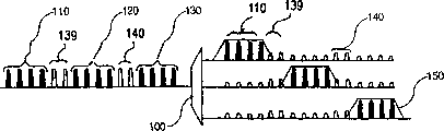
This is shown in Figure 1.The optical demultiplexer 100 of routine shown in Fig. 1, it has extracted the wavestrip of three separation respectively, and described wavestrip is made up of the channel sequence that distributes with fixed intervals in frequency spectrum.
The wavestrip 110 that four channels that carried respectively by first group of four wavelength are formed;
The wavestrip 120 that four channels that carried respectively by second group of four wavelength are formed; And
The wavestrip 130 that four channels that carried respectively by the 3rd group of four wavelength are formed.
Wavestrip 110 and 120 is separated by the wavestrip that is not used in transmission signals 139 corresponding with two channels.Wavestrip 120 and 130 is separated by the wavestrip that is not used in transmission signals 140 corresponding with two channels.When using conventional wavestrip demultiplexing equipment, do not sacrifice wavestrip 110 and 120 and wavestrip 120 and 130 between so-called " interband frequency band (inter-band) " channel just can't extract wavestrip 110,120 and 130.This is very near (the interchannel spectrum intervals comprises 100GHz, 50GHz because of the continuous wavelength that can transmit under so-called DWDM pattern, perhaps in addition 25GHz), and common wavestrip demultiplexing equipment, limited as the eigenfrequency spectrum resolution capability (being also referred to as selectivity) of demodulation multiplexer 100.
In Fig. 1, the passband of conventional demodulation multiplexer 100 is by trapezoidal 150 expressions with steep inadequately hypotenuse.This passband width enough covers the channel (being four channels in this example) of wavestrip, but the selectivity of this passband is not enough to eliminate effectively the interband wavestrip channel that constitutes wavestrip 139 and 140.Therefore, these interband wavestrip channels can not be utilized, thereby have reduced the transmission capacity of optical fiber significantly.
Summary of the invention
The purpose of this invention is to provide a kind of Optical Demultiplexing system, it can effectively utilize and not use the interband wavestrip wavelength that will lose.
The invention provides a kind of optical demultiplexer system, be used to separate the single wavestrip of forming first pectination wavestrip part, the described first pectination wavestrip is intersected with at least one second pectination wavestrip, and each wavestrip is made of a plurality of channels with adjacent wavelength, and described system is characterised in that it comprises:
The first frequency spectrum demodulation multiplexer level is used for extracting respectively each pectination wavestrip; And
The second frequency spectrum demodulation multiplexer level is used for extracting respectively formation each wavestrip by the pectination wavestrip of described first filter stage extraction.
System of the present invention can utilize all channels, is considered to the channel of interband wavestrip channel especially usually, and these channels were not used in transmission signals in the past.System of the present invention only need use simple and cheap device in every two-stage, just can obtain enough selectivity, thereby can use interband wavestrip channel, especially be used for network management and wavestrip the management.
Description of drawings
By following detailed description to the preferred embodiment for the present invention shown in the accompanying drawing, can more be clear that purpose of the present invention, theme, characteristics and advantage, wherein:
Fig. 1 as mentioned above, shows the transmission mode of prior art, and wherein a large amount of wavelength are by same Optical Fiber Transmission, and the channel between interband wavestrip wherein can not use;
Fig. 2 illustrates first execution mode of optical demultiplexer of the present invention system; And
Fig. 3 illustrates second execution mode of optical demultiplexer of the present invention system.
Embodiment
In the execution mode shown in Fig. 2, transmission multiplexed signals 200 on optical fiber 205.It is made up of the channel that distributes with fixed intervals.Multiplexed signals 200 comprises the pectination wavestrip of two intersections:
Form the first wavestrip pectination wavestrip 321 by three wavestrip 321a, 321b, 321c, wherein each wavestrip is made up of four channels of transmission signals; And
Form the second wavestrip pectination wavestrip 320 by two wavestrip 320a and 320b, wherein each wavestrip is made up of two " interband wavestrip " channels that also are used for transmission signals.
This system comprises:
Have narrow relatively passband and the relative high optionally first frequency spectrum demultiplexing level, its major function is to extract all interband wavestrip channels; And
Have wide relatively passband and the relative low optionally second frequency spectrum demultiplexing level, be used for extract all interband wavestrip channels by the first order after, separating remaining wavestrip.
Because the frequency band of interband wavestrip channel is narrow, therefore construct the first order easily with high selectivity, the second level can be to have low optionally conventional demodulation multiplexer, because the first order has been eliminated interband wavestrip channel very effectively.
The first order is separated interleaver (deinterlacer) 210 by the cycle wavestrip that is used for separately two pectination wavestrips 320 and 321 and is constituted.First output of explaining interleaver 210 by oneself provides the pectination wavestrip 320 that comprises all interband wavestrip channels ( wavestrip 320a and 320b).In first example, these channels are extracted but keep general multiplexing state.Two wavestrip 320a and 320b can be used for transmission signals, but they are not separately.Second output of explaining interleaver 210 by oneself provides the pectination wavestrip 321 of the channel that has comprised the transmission information that is useful on.Wave band is separated interleaver 210 and preferably is made of Periodic filter (or Periodic filter string), this filter has enough selectivity, so that can effectively weaken wavestrip 320a and the 320b that offers the interband wavestrip channel in the second output multiplexed signals (comprising wavestrip 321a, 321b and 321c).
The second level is made of cycle wavestrip demodulation multiplexer 240.It has three outputs, exports wavestrip 321a respectively, 321b and 321c.Because interband wavestrip channel ( wavestrip 320a and 320b) is formerly by the extracting of the first order 210 high selectivities, the demodulation multiplexer that therefore constitutes the second level 240 can be to have the demodulation multiplexer that low frequency spectrum optionally is used for the routine of continuous wavestrip.
Separate the realization of interleaver 210 in the first order and used technology well known to those skilled in the art.Yet, still in the part of the amplification of Fig. 2, be shown specifically this and separate interleaver.It comprises circulator 252, and this circulator has the input that links to each other with filter 205, and with periodic light filter 254, Fabry-Perot filter for example, the first continuous output.The frequency spectrum separating power of filter 254 must be enough to extract the wavestrip 320a and the 320b of interband wavestrip channel.These wavestrips appear at the output 256 of Periodic filter 254.Second output 258 of circulator 252 constitutes second output of separating interleaver 210 that transmits wavestrip 321a, 321b and 321c.Should be noted that therefore preferably it to be replaced with isolator because circulator 252 is expensive component, the back connects a simple coupler.
Fig. 3 has reappeared most contents among Fig. 2.It illustrates two interband wavestrip channel 320a and 320b and is separated demodulation multiplexer system under the operating position.The device in first execution mode shown in Fig. 2, this second execution mode also comprises the cycle wavestrip demodulation multiplexer 360 with an input and two outputs, its input links to each other with first output of separating interleaver 210, and its output is used for extracting respectively wavestrip 320a and the 320b that is used for transmission signals equally.
Each cycle wavestrip demodulation multiplexer 240 and 360 preferably includes the Periodic filter that is formed by stringer (deposited thin layers).
Like this, the present invention just can utilize interband wavestrip channel, and they normally can not be utilized in the past.In preferred implementation of the present invention, these channels are used for Control Network self, the carrying all-network normally moves and make network to remain on the required information of best performance level.When adopting when coming interconnected OADM equipment, need the effective utilization of careful management talent need be in the OADM equipment local wavestrip of road or insertion up and down based on the DWDM pattern of the multiplexing a large amount of technology of wavelength to optical fiber.The one or more control channels of this managerial demand, these control channels can preferably use the interband wavestrip wavelength that is utilized once more by enforcement of the present invention.
At last, should be noted that the number that Fig. 1 to Fig. 3 illustrates interband wavestrip channel all is two, and in practice can be with only two of numbers as specific examples are different when the explanation prior art with when of the present invention.Especially, in a preferred embodiment of the present invention, can only use an interband wavestrip channel by selecting wavestrip demodulation multiplexer 240, as long as the enough height of selectivity or the interval between the wavelength of this demodulation multiplexer 240 are enough big.This can obtain man-to-man corresponding relation in wavestrip and one or several continuous interband wavestrip interchannel, and wherein interband wavestrip channel can be used to control wavestrip.
Claims (5)
1. optical demultiplexer system, be used for separating the single wavestrip (321a) of the part of forming the first pectination wavestrip (321) that comprises the wavestrip that first group of a plurality of interval separates, the described first pectination wavestrip is intersected with the second pectination wavestrip (320) that at least one comprises the wavestrip that second group of a plurality of interval separates, each wavestrip of the described first pectination wavestrip is made of a plurality of channels with adjacent wavelength, each wavestrip of the described second pectination wavestrip is made of at least one wavelength, and described system is characterised in that this system comprises:
The first frequency spectrum demodulation multiplexer level (210) is used for extracting respectively each described first and second pectination wavestrip (320,321); And
The second frequency spectrum demodulation multiplexer level (240; 360), be used for extracting respectively at least the first pectination wavestrip that formation extracted by the described first order each wavestrip (321a ...);
The described first order has first narrow relatively passband and the relative first high selectivity; And
The described second level has second passband wideer than described first passband, and has second selectivity lower than described first selectivity.
2. optical demultiplexer according to claim 1 system is characterized in that the described first order (210) comprises Periodic filter, and this filter comprises circulator (252) and Fabry-Perot type Periodic filter (254).
3. optical demultiplexer according to claim 1 system is characterized in that the described second level (240; 360) comprise the Periodic filter that constitutes by stringer.
4. optical demultiplexer according to claim 1 system, each wavestrip in wherein said first group of a plurality of wavestrip is made up of first group of a plurality of channel that one group of different wave length carries respectively; And
Wherein said second group of a plurality of wavestrip are made up of the second group of a plurality of channel that is less than described first group of a plurality of channel.
5. optical demultiplexer according to claim 4 system, wherein said first group of a plurality of channel are 4 channels, and wherein said second group of a plurality of channel are 2 channels.
Applications Claiming Priority (4)
| Application Number | Priority Date | Filing Date | Title |
|---|---|---|---|
| FR0112448A FR2830144A1 (en) | 2001-09-27 | 2001-09-27 | Internet demultiplexing high wavelength number fibre optic transmission having low pass band/high selectivity filtering extracting without loss interband channels and second stage wide pass band low selectivity. |
| FR01/12448 | 2001-09-27 | ||
| FR0113102A FR2830145B1 (en) | 2001-09-27 | 2001-10-11 | OPTICAL DEMULTIPLEXING SYSTEM OF WAVELENGTH BANDS |
| FR01/13102 | 2001-10-11 |
Publications (2)
| Publication Number | Publication Date |
|---|---|
| CN1579061A CN1579061A (en) | 2005-02-09 |
| CN1301602C true CN1301602C (en) | 2007-02-21 |
Family
ID=26213198
Family Applications (1)
| Application Number | Title | Priority Date | Filing Date |
|---|---|---|---|
| CNB028214072A Expired - Fee Related CN1301602C (en) | 2001-09-27 | 2002-09-26 | System for optical demultiplexing of wavelength bands |
Country Status (6)
| Country | Link |
|---|---|
| US (1) | US7085447B2 (en) |
| EP (1) | EP1300975A1 (en) |
| JP (1) | JP2005504478A (en) |
| CN (1) | CN1301602C (en) |
| FR (1) | FR2830145B1 (en) |
| WO (1) | WO2003028263A1 (en) |
Families Citing this family (13)
| Publication number | Priority date | Publication date | Assignee | Title |
|---|---|---|---|---|
| US8073689B2 (en) * | 2003-02-21 | 2011-12-06 | Qnx Software Systems Co. | Repetitive transient noise removal |
| US7895036B2 (en) * | 2003-02-21 | 2011-02-22 | Qnx Software Systems Co. | System for suppressing wind noise |
| US8271279B2 (en) | 2003-02-21 | 2012-09-18 | Qnx Software Systems Limited | Signature noise removal |
| US7949522B2 (en) | 2003-02-21 | 2011-05-24 | Qnx Software Systems Co. | System for suppressing rain noise |
| US8326621B2 (en) | 2003-02-21 | 2012-12-04 | Qnx Software Systems Limited | Repetitive transient noise removal |
| US7885420B2 (en) | 2003-02-21 | 2011-02-08 | Qnx Software Systems Co. | Wind noise suppression system |
| US7725315B2 (en) * | 2003-02-21 | 2010-05-25 | Qnx Software Systems (Wavemakers), Inc. | Minimization of transient noises in a voice signal |
| CN1866808B (en) * | 2005-05-21 | 2010-04-28 | 华为技术有限公司 | Multiplex/demultiplex method and apparatus for wavelength-division multiplex system |
| CN100549741C (en) * | 2006-08-21 | 2009-10-14 | 中兴通讯股份有限公司 | A kind of packet filtering device of non-black wavelength and packet filtering method thereof |
| JP2008259134A (en) * | 2007-04-09 | 2008-10-23 | Nippon Telegr & Teleph Corp <Ntt> | Wavelength selection switch, optical cross-connect device, wavelength selecting method, and signal control method in optical cross-connect device |
| JP2008259132A (en) * | 2007-04-09 | 2008-10-23 | Nippon Telegr & Teleph Corp <Ntt> | Optical cross-connect system and signal control method of optical cross-connect system |
| JP2008259129A (en) * | 2007-04-09 | 2008-10-23 | Nippon Telegr & Teleph Corp <Ntt> | Optical network system using optical cross-connect apparatus |
| US20100260500A1 (en) * | 2009-04-08 | 2010-10-14 | Nec Laboratories America Inc | Mult9-degree wavelength cross-connect using bidirectional wavelength selective switch |
Citations (2)
| Publication number | Priority date | Publication date | Assignee | Title |
|---|---|---|---|---|
| US6040932A (en) * | 1997-04-25 | 2000-03-21 | Duck; Gary S. | Method and circuit for demultiplexing an optical signal |
| US6067178A (en) * | 1997-09-16 | 2000-05-23 | Oplink Communications, Inc. | Multiple wavelength division multiplexer with reduced loss |
Family Cites Families (7)
| Publication number | Priority date | Publication date | Assignee | Title |
|---|---|---|---|---|
| US6208444B1 (en) * | 1996-10-29 | 2001-03-27 | Chorum Technologies Inc. | Apparatus for wavelength demultiplexing using a multi-cavity etalon |
| EP0874489A3 (en) * | 1997-04-25 | 2002-05-29 | Jds Fitel Inc. | Method and circuit for demultiplexing an optical signal |
| US6310690B1 (en) * | 1999-02-10 | 2001-10-30 | Avanex Corporation | Dense wavelength division multiplexer utilizing an asymmetric pass band interferometer |
| JP4044253B2 (en) * | 1999-04-05 | 2008-02-06 | 株式会社東芝 | Optical add / drop node equipment |
| CA2379155A1 (en) * | 1999-07-13 | 2001-01-18 | Jds Uniphase Corporation | Method and devices for multiplexing and de-multiplexing multiple wavelengths |
| US6388783B1 (en) * | 1999-11-30 | 2002-05-14 | Corning Incorporated | Narrow band wavelength division multiplexer and method of multiplexing optical signals |
| FR2818080B1 (en) * | 2000-12-07 | 2003-03-28 | Cit Alcatel | DEMULTIPLEXING / MULTIPLEXING SYSTEM IN INTERLEAVED BANDS |
-
2001
- 2001-10-11 FR FR0113102A patent/FR2830145B1/en not_active Expired - Lifetime
-
2002
- 2002-09-26 WO PCT/FR2002/003280 patent/WO2003028263A1/en active Application Filing
- 2002-09-26 US US10/491,147 patent/US7085447B2/en not_active Expired - Lifetime
- 2002-09-26 EP EP02292364A patent/EP1300975A1/en not_active Withdrawn
- 2002-09-26 JP JP2003531653A patent/JP2005504478A/en active Pending
- 2002-09-26 CN CNB028214072A patent/CN1301602C/en not_active Expired - Fee Related
Patent Citations (2)
| Publication number | Priority date | Publication date | Assignee | Title |
|---|---|---|---|---|
| US6040932A (en) * | 1997-04-25 | 2000-03-21 | Duck; Gary S. | Method and circuit for demultiplexing an optical signal |
| US6067178A (en) * | 1997-09-16 | 2000-05-23 | Oplink Communications, Inc. | Multiple wavelength division multiplexer with reduced loss |
Also Published As
| Publication number | Publication date |
|---|---|
| WO2003028263A1 (en) | 2003-04-03 |
| JP2005504478A (en) | 2005-02-10 |
| FR2830145A1 (en) | 2003-03-28 |
| US20050238283A1 (en) | 2005-10-27 |
| FR2830145B1 (en) | 2004-04-16 |
| CN1579061A (en) | 2005-02-09 |
| EP1300975A1 (en) | 2003-04-09 |
| US7085447B2 (en) | 2006-08-01 |
Similar Documents
| Publication | Publication Date | Title |
|---|---|---|
| CN1802808A (en) | Flexible banded mux/demux architecture for WDM systems | |
| CN1301602C (en) | System for optical demultiplexing of wavelength bands | |
| CA2255346C (en) | Optical multiplexor/demultiplexor | |
| US8958695B2 (en) | Optical adding and dropping device and optical transmission apparatus | |
| US20090047019A1 (en) | Method and System for Communicating Optical Traffic | |
| JPH11503537A (en) | Multi-wavelength filtering device using optical fiber Bragg grating | |
| CN1832384A (en) | Wavelength grid for dwdm | |
| CN1494776A (en) | Bidirectional WDM optical communicatrion network with data bridging plural optical channels between bidirectional optical waveguides | |
| US7805077B2 (en) | Scalable and movable DWDM usage of CWDM networks | |
| Ab-Rahman et al. | OXADM restoration scheme: Approach to optical ring network protection | |
| CN1190025C (en) | DWDM optical source wavelength control | |
| CN102572621A (en) | Optical module and wavelength division multiplexing system | |
| US7426323B2 (en) | Dispersion management in branched optical networks | |
| US6885822B1 (en) | Wavelength and filter arrangement for WDM networks | |
| EP1076471B1 (en) | Optical wavelength division multiplexing transmission network device | |
| CN1209647C (en) | Optical cross-linking system | |
| EP0977394A2 (en) | Bidirectional ring networks implemented on a single fiber | |
| US6546166B1 (en) | Multi-stage optical DWDM channel group interleaver | |
| US6493118B1 (en) | Add/drop capability for ultra-high speed dense wavelength division multiplexed systems using a wavelength bus architecture | |
| JP4845268B2 (en) | High performance optical add / drop multiplexer and wavelength division multiplexing optical network | |
| US6901184B2 (en) | Frequency comb for an optical WDM network | |
| CN1514566A (en) | Same wave length single fiber biairection sparse interleave multiplex transmission system | |
| CA2351808C (en) | A method and apparatus for demultiplexing high bit rate optical signals on a dense wavelength grid | |
| CN1319965A (en) | Equipment for multiplexing/demultiplexing optical signal modulated by different data rate | |
| KR100429042B1 (en) | Bidirectional wavelength division multiplexed self-healing ring network composed of a add fiber and a drop fiber |
Legal Events
| Date | Code | Title | Description |
|---|---|---|---|
| C06 | Publication | ||
| PB01 | Publication | ||
| C10 | Entry into substantive examination | ||
| SE01 | Entry into force of request for substantive examination | ||
| C14 | Grant of patent or utility model | ||
| GR01 | Patent grant | ||
| CF01 | Termination of patent right due to non-payment of annual fee |
Granted publication date: 20070221 Termination date: 20170926 |
|
| CF01 | Termination of patent right due to non-payment of annual fee |