EP1300928B1 - Small-sized motor and manufacturing thereof - Google Patents
Small-sized motor and manufacturing thereof Download PDFInfo
- Publication number
- EP1300928B1 EP1300928B1 EP02022087.7A EP02022087A EP1300928B1 EP 1300928 B1 EP1300928 B1 EP 1300928B1 EP 02022087 A EP02022087 A EP 02022087A EP 1300928 B1 EP1300928 B1 EP 1300928B1
- Authority
- EP
- European Patent Office
- Prior art keywords
- case
- metal case
- case cover
- printed board
- attached
- Prior art date
- Legal status (The legal status is an assumption and is not a legal conclusion. Google has not performed a legal analysis and makes no representation as to the accuracy of the status listed.)
- Expired - Lifetime
Links
Images


Classifications
-
- H—ELECTRICITY
- H02—GENERATION; CONVERSION OR DISTRIBUTION OF ELECTRIC POWER
- H02K—DYNAMO-ELECTRIC MACHINES
- H02K5/00—Casings; Enclosures; Supports
- H02K5/04—Casings or enclosures characterised by the shape, form or construction thereof
- H02K5/15—Mounting arrangements for bearing-shields or end plates
-
- H—ELECTRICITY
- H02—GENERATION; CONVERSION OR DISTRIBUTION OF ELECTRIC POWER
- H02K—DYNAMO-ELECTRIC MACHINES
- H02K11/00—Structural association of dynamo-electric machines with electric components or with devices for shielding, monitoring or protection
- H02K11/02—Structural association of dynamo-electric machines with electric components or with devices for shielding, monitoring or protection for suppression of electromagnetic interference
- H02K11/026—Suppressors associated with brushes, brush holders or their supports
-
- H—ELECTRICITY
- H02—GENERATION; CONVERSION OR DISTRIBUTION OF ELECTRIC POWER
- H02K—DYNAMO-ELECTRIC MACHINES
- H02K11/00—Structural association of dynamo-electric machines with electric components or with devices for shielding, monitoring or protection
- H02K11/02—Structural association of dynamo-electric machines with electric components or with devices for shielding, monitoring or protection for suppression of electromagnetic interference
- H02K11/028—Suppressors associated with the rotor
-
- H—ELECTRICITY
- H02—GENERATION; CONVERSION OR DISTRIBUTION OF ELECTRIC POWER
- H02K—DYNAMO-ELECTRIC MACHINES
- H02K11/00—Structural association of dynamo-electric machines with electric components or with devices for shielding, monitoring or protection
- H02K11/40—Structural association with grounding devices
-
- H—ELECTRICITY
- H02—GENERATION; CONVERSION OR DISTRIBUTION OF ELECTRIC POWER
- H02K—DYNAMO-ELECTRIC MACHINES
- H02K5/00—Casings; Enclosures; Supports
- H02K5/04—Casings or enclosures characterised by the shape, form or construction thereof
- H02K5/14—Means for supporting or protecting brushes or brush holders
- H02K5/143—Means for supporting or protecting brushes or brush holders for cooperation with commutators
- H02K5/145—Fixedly supported brushes or brush holders, e.g. leaf or leaf-mounted brushes
-
- H—ELECTRICITY
- H02—GENERATION; CONVERSION OR DISTRIBUTION OF ELECTRIC POWER
- H02K—DYNAMO-ELECTRIC MACHINES
- H02K5/00—Casings; Enclosures; Supports
- H02K5/04—Casings or enclosures characterised by the shape, form or construction thereof
- H02K5/22—Auxiliary parts of casings not covered by groups H02K5/06-H02K5/20, e.g. shaped to form connection boxes or terminal boxes
- H02K5/225—Terminal boxes or connection arrangements
-
- Y—GENERAL TAGGING OF NEW TECHNOLOGICAL DEVELOPMENTS; GENERAL TAGGING OF CROSS-SECTIONAL TECHNOLOGIES SPANNING OVER SEVERAL SECTIONS OF THE IPC; TECHNICAL SUBJECTS COVERED BY FORMER USPC CROSS-REFERENCE ART COLLECTIONS [XRACs] AND DIGESTS
- Y10—TECHNICAL SUBJECTS COVERED BY FORMER USPC
- Y10S—TECHNICAL SUBJECTS COVERED BY FORMER USPC CROSS-REFERENCE ART COLLECTIONS [XRACs] AND DIGESTS
- Y10S310/00—Electrical generator or motor structure
- Y10S310/06—Printed-circuit motors and components
-
- Y—GENERAL TAGGING OF NEW TECHNOLOGICAL DEVELOPMENTS; GENERAL TAGGING OF CROSS-SECTIONAL TECHNOLOGIES SPANNING OVER SEVERAL SECTIONS OF THE IPC; TECHNICAL SUBJECTS COVERED BY FORMER USPC CROSS-REFERENCE ART COLLECTIONS [XRACs] AND DIGESTS
- Y10—TECHNICAL SUBJECTS COVERED BY FORMER USPC
- Y10T—TECHNICAL SUBJECTS COVERED BY FORMER US CLASSIFICATION
- Y10T29/00—Metal working
- Y10T29/49—Method of mechanical manufacture
- Y10T29/49002—Electrical device making
- Y10T29/49009—Dynamoelectric machine
- Y10T29/49011—Commutator or slip ring assembly
-
- Y—GENERAL TAGGING OF NEW TECHNOLOGICAL DEVELOPMENTS; GENERAL TAGGING OF CROSS-SECTIONAL TECHNOLOGIES SPANNING OVER SEVERAL SECTIONS OF THE IPC; TECHNICAL SUBJECTS COVERED BY FORMER USPC CROSS-REFERENCE ART COLLECTIONS [XRACs] AND DIGESTS
- Y10—TECHNICAL SUBJECTS COVERED BY FORMER USPC
- Y10T—TECHNICAL SUBJECTS COVERED BY FORMER US CLASSIFICATION
- Y10T29/00—Metal working
- Y10T29/49—Method of mechanical manufacture
- Y10T29/49002—Electrical device making
- Y10T29/49009—Dynamoelectric machine
- Y10T29/49012—Rotor
-
- Y—GENERAL TAGGING OF NEW TECHNOLOGICAL DEVELOPMENTS; GENERAL TAGGING OF CROSS-SECTIONAL TECHNOLOGIES SPANNING OVER SEVERAL SECTIONS OF THE IPC; TECHNICAL SUBJECTS COVERED BY FORMER USPC CROSS-REFERENCE ART COLLECTIONS [XRACs] AND DIGESTS
- Y10—TECHNICAL SUBJECTS COVERED BY FORMER USPC
- Y10T—TECHNICAL SUBJECTS COVERED BY FORMER US CLASSIFICATION
- Y10T29/00—Metal working
- Y10T29/49—Method of mechanical manufacture
- Y10T29/49002—Electrical device making
- Y10T29/4902—Electromagnet, transformer or inductor
- Y10T29/49073—Electromagnet, transformer or inductor by assembling coil and core
-
- Y—GENERAL TAGGING OF NEW TECHNOLOGICAL DEVELOPMENTS; GENERAL TAGGING OF CROSS-SECTIONAL TECHNOLOGIES SPANNING OVER SEVERAL SECTIONS OF THE IPC; TECHNICAL SUBJECTS COVERED BY FORMER USPC CROSS-REFERENCE ART COLLECTIONS [XRACs] AND DIGESTS
- Y10—TECHNICAL SUBJECTS COVERED BY FORMER USPC
- Y10T—TECHNICAL SUBJECTS COVERED BY FORMER US CLASSIFICATION
- Y10T29/00—Metal working
- Y10T29/49—Method of mechanical manufacture
- Y10T29/49002—Electrical device making
- Y10T29/4902—Electromagnet, transformer or inductor
- Y10T29/49075—Electromagnet, transformer or inductor including permanent magnet or core
- Y10T29/49076—From comminuted material
-
- Y—GENERAL TAGGING OF NEW TECHNOLOGICAL DEVELOPMENTS; GENERAL TAGGING OF CROSS-SECTIONAL TECHNOLOGIES SPANNING OVER SEVERAL SECTIONS OF THE IPC; TECHNICAL SUBJECTS COVERED BY FORMER USPC CROSS-REFERENCE ART COLLECTIONS [XRACs] AND DIGESTS
- Y10—TECHNICAL SUBJECTS COVERED BY FORMER USPC
- Y10T—TECHNICAL SUBJECTS COVERED BY FORMER US CLASSIFICATION
- Y10T29/00—Metal working
- Y10T29/49—Method of mechanical manufacture
- Y10T29/49002—Electrical device making
- Y10T29/49117—Conductor or circuit manufacturing
- Y10T29/49169—Assembling electrical component directly to terminal or elongated conductor
-
- Y—GENERAL TAGGING OF NEW TECHNOLOGICAL DEVELOPMENTS; GENERAL TAGGING OF CROSS-SECTIONAL TECHNOLOGIES SPANNING OVER SEVERAL SECTIONS OF THE IPC; TECHNICAL SUBJECTS COVERED BY FORMER USPC CROSS-REFERENCE ART COLLECTIONS [XRACs] AND DIGESTS
- Y10—TECHNICAL SUBJECTS COVERED BY FORMER USPC
- Y10T—TECHNICAL SUBJECTS COVERED BY FORMER US CLASSIFICATION
- Y10T29/00—Metal working
- Y10T29/49—Method of mechanical manufacture
- Y10T29/49002—Electrical device making
- Y10T29/49117—Conductor or circuit manufacturing
- Y10T29/49174—Assembling terminal to elongated conductor
- Y10T29/49179—Assembling terminal to elongated conductor by metal fusion bonding
Definitions
- the present invention relates to a small-sized motor, and more particularly relates to a small-sized motor wherein an electric element such as a capacitor is attached to a case cover for being used for the driving of electrical equipment or the like.
- a small-sized motor is widely used in a vehicle electrical apparatus such as a vehicle door lock opening and closing device, an electrically powered mirror mirror-surface driving and containing device, or an air conditioner.
- a vehicle electrical apparatus such as a vehicle door lock opening and closing device, an electrically powered mirror mirror-surface driving and containing device, or an air conditioner.
- the reduction of electric noise caused at the time of operation is required, and regulations are laid down all over the world.
- CISPR25 as an international standard, GMW3100/3097 as a carmaker standard, or the like can be mentioned.
- US 5 196 750 A discloses a small sized motor with a metal case with a bottom where a magnet is attached to an inside periphery.
- the small sized motor comprises a cylindrical metal case and a resin case cover.
- a printed board is mounted, both mechanically and electrically in the resin case cover by soldering it to members being connected to a power source. By connecting the resin case cover to the motor metal case the printed board is electrically connected to
- a printed board mounting method as shown in FIG. 6 is conventionally well known (refer to Japanese Utility Model Publication No. 63-127254 ).
- a printed board 25 to which an electric element (omitted in the drawing) is attached is structured such that it is mounted to a metal case 1 where the motor main body (omitted in the drawing) is contained, and after that, furthermore, it is covered by a case cover (omitted in the drawing).
- a projecting needle part 26 projected from an opening end edge is provided, and in the meantime, corresponding to this projecting needle part 26, to the printed board 25, an engaging part 28 which makes the projecting needle part 26 pass to an earth electrode part 27 is provided.
- the printed board 25 is mounted on the metal case 1, and after that, by performing the soldering of the projecting needle part 26 and the earth electrode part 27, the earth electrode part 27 of the printed board 25 and the metal case 1 are electrically connected through the solder.
- the manufacturing method comprises steps of: inserting a rotor where a laminated core, a winding wound around said laminated core, and a commutator are attached on a shaft, into a hollow cylindrical metal case with a bottom where a magnet is attached to an inside periphery; mounting to a synthethic resin case cover a printed board where an electric circuit including an electric element is attached, fitting said case cover to close an opening part of said metal case, characterised in that said printed board has a soldering part which is connected to a member attached to the interior of the case cover for being connected to an electric power source supplied from the outside and a soldering part which is connected to a projection in a notch provided on the opening part side of said metal case for body-earthing the earth of said electric circuit, and at the time of assembling the motor, after fitting said case cover to said metal case opening part, a pair of electrodes are brought into contact with the metal case from the outside of the metal case
- FIG. 1 is a vertical cross sectional view showing a total of a small-sized motor to which the present invention can be applied by an upper half cross section.
- a magnet 2 (refer to FIG. 4D ) is attached to an inside periphery of a case 1 formed like a hollow cylinder with a bottom by a metal material.
- a synthetic resin case cover 11 is fitted, and the opening part is closed by the case cover 11.
- a bearing 3 for a shaft 21 is contained in a center of the case cover 11.
- the other end of the shaft 21 is supported by a bearing 3 provided at a center of the bottom part of the hollow cylindrical case 1 with a bottom.
- a laminated core 22, a winding 23 wound on the above described core 22, and a commutator 24 are usually provided to compose a rotor of a small-sized motor. Then, each of a pair of carbon brushes coming into contact with this commutator 24 is attached to the brush device fixed to the case cover 11.
- FIG. 3 is a view showing only a case cover of a small-sized motor shown in FIG. 1 .
- FIG. 3A is a view of an interior seen from an inside direction of the case cover
- FIG. 3B is a cross sectional view made by cutting the case cover shown in FIG. 3A at the center.
- the brush device is made of a pair of carbon brushes 4 coming into sliding contact with the commutator, brush arms 5 where they are respectively pressed and held, and brush bases 6, 7 connected to these brush arms 5 by caulking or the like.
- the brush device structured like this is pressed and held in the concave place limited by the columned part integrally formed with that.
- the electric power source supply to this brush device is performed through a pair of brush springs 8 functioning as the receptacle terminals coming into electric contact with a pair of external terminals inserted from the outside through the external terminal inserting holes.
- one brush spring is connected to the brush base 6 electrically directly, and the other brush spring is connected to the brush base 7 in series through the choke coil 16.
- the above described attachment configuration of the brush device and electric power source supply configuration thereto can be made by a conventionally well known normal technique.
- the present invention is characterized by such a structure where to the case cover of a small-sized motor to which a brush device like this is attached, a printed board 12 to which an electric circuit element for the reduction of noise is attached is furthermore mounted, and in the meantime, the earth of this electric circuit is body-earthed to the metal case.
- FIG. 2 a typical electric circuit used for the reduction of noise is exemplified.
- Three circuits shown in (A) to (C) themselves are well known, but which circuit should be used (or whether another circuit should furthermore be used) is determined by the target value of how much the electric noise should be reduced.
- a choke coil L of the circuit element shown in the drawing can directly be attached to the case cover as mentioned above (refer to the choke coil 16 shown in FIG. 3 (A) ).
- Chip capacitors C1 to C3 except for the choke coil L and the winding thereof are put into practice by using the printed circuit.
- FIG. 5 is a view exemplifying the printed board.
- the exemplified printed board in order to make the circuit shown in FIG. 2A , as an electric element, only one chip capacitor 15 is attached.
- the printed board for example, at the time of changing from the circuit shown in FIG. 2A to the circuit shown in FIG. 2B or FIG. 2C , or to another circuit, the changing can be performed only by changing the printed board itself where the circuit element is assembled without changing the assembled structure of the case cover at all.
- a slant hatching portion shows a winding portion on the printed board, and the soldering is performed at a black portion.
- soldering parts 17, 18, the soldering is performed with the extension parts 13 extending upward from the end parts of a pair of brush springs 8. Consequently, for the printed board which is pressed and held in the concave place limited by the columned part formed integrally with the synthetic resin case cover, the printed board is not only being electrically connected but also is mechanically surely fixed In the case cover by this soldering. Consequently, the assembling of the case cover itself is finished, and after that, the step advances to the assembling step of the total of the small-sized motor.
- a metal case to which a magnet is attached, a rotor where the assembly is completed, and a case cover where the assembly is completed are prepared. Then, after letting one end of the rotor shaft pass through the bearing at the metal case bottom part, the case cover is fitted to the opening part of the metal case, and after that, not only the soldering part 14 on the printed board is mechanically connected to the projection in the notch provided to the case cover to be described later by soldering but also it is body-earthed, so that the assembling as the small-sized motor is completed.
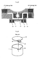
- FIG. 4 is a view showing the metal case
- FIG. 4D is a view made by seeing an interior from an opening part of the metal case, and a view made by seeing this drawing ( FIG. 4D ) from the upper side is FIG. 4A , and a view showing that by an upper half cross section seen from the side is FIG. 4C.
- FIG. 4B is a view showing an expanded projection 10 provided on the opening part side of the metal case.
- the projection 10 in the notch 9 provided to the metal case is provided at such a position where the soldering part 14 on the printed board comes into contact with this projection 10 when the case cover is fitted to the metal case opening part.
- solder of a specified amount is already heaped up in advance before fitting the case cover.
- the tip of the projection 10 is positioned at a place retreated from the metal case opening part end surface by an amount approximately equal to the amount by which the soldering part 14 is made higher with the heaped solder.
- two projections 10 are provided in the notches 9, and furthermore, corresponding thereto, the soldering parts 14 are provided at four places (refer to FIG.
- the tip side thereof is bent in the metal case interior direction. It is undesirable from the point of view of the beauty that the solder runs over in the outside direction of the case at the time of performing the soldering to be described later, but by bending the tip side in the inside direction like this, the solder can be prevented from running over in the outside direction of the case.
- the projection 10 comes into contact with the soldering part 14 on the printed board, and even if part thereof bites in, the connection is not completed yet in this state.
- the solder is melted by the principle of the electric resistance welding to make the contact and the connection more stable.
- This electric resistance welding is performed by bringing a pair of electrodes for the electric resistance welding into contact with a part where heating is necessary, that is, a place near the projection 10 (refer to FIG. 4A ).
- the electric resistance welding is performed after fitting the case cover to the metal case.
- the heating is performed between the electrodes because of the electric resistance included in the steel metal case, and the heat thereof is transmitted to the projection 10, and consequently, the solder is melted by the principle of the electric resistance welding, and the welding is performed.
- the present invention makes it possible to easily and surely body-earth the earth of the electric circuit made of the electric element such as a chip capacitor attached on a printed board mounted to a case cover, to a metal case.
- the present invention makes it possible to reduce the number of motor assembling steps to perform the assembling with a good workability.
- the projection in the notch can prevent the solder from running over in the outside direction of the case by bending the tip side thereof in the metal case interior direction.
Description
- The present invention relates to a small-sized motor, and more particularly relates to a small-sized motor wherein an electric element such as a capacitor is attached to a case cover for being used for the driving of electrical equipment or the like.
- A small-sized motor is widely used in a vehicle electrical apparatus such as a vehicle door lock opening and closing device, an electrically powered mirror mirror-surface driving and containing device, or an air conditioner. In the case of the small-sized motor and the peripheral equipment like this, the reduction of electric noise caused at the time of operation is required, and regulations are laid down all over the world. CISPR25 as an international standard, GMW3100/3097 as a carmaker standard, or the like can be mentioned.
US 5 196 750 A discloses a small sized motor with a metal case with a bottom where a magnet is attached to an inside periphery. The small sized motor comprises a cylindrical metal case and a resin case cover. A printed board is mounted, both mechanically and electrically in the resin case cover by soldering it to members being connected to a power source. By connecting the resin case cover to the motor metal case the printed board is electrically connected to the metal case. - In order to reduce the electric noise, in the case of a small-sized motor, it is necessary to directly attach the electric element such as a capacitor or a choke coil to the motor. Therefore, conventionally, it has been performed that the electric element is arranged and wired on a printed board, and that this printed board is mounted on the motor. However, in the case of a mounting method like this, such a work is necessary, where a special earth lead wire for earthing the electric circuit is connected to the printed board in advance, and furthermore, this printed board is mounted on a metal case of the motor, and after that, the above described earth lead wire is connected, for example, by soldering.
- In order to reduce the man-hour of such a troublesome work, a printed board mounting method as shown in
FIG. 6 is conventionally well known (refer to Japanese Utility Model Publication No.63-127254 FIG. 6 , a printedboard 25 to which an electric element (omitted in the drawing) is attached is structured such that it is mounted to ametal case 1 where the motor main body (omitted in the drawing) is contained, and after that, furthermore, it is covered by a case cover (omitted in the drawing). - As shown in the drawing, to the
metal case 1, a projectingneedle part 26 projected from an opening end edge is provided, and in the meantime, corresponding to this projectingneedle part 26, to the printedboard 25, anengaging part 28 which makes the projectingneedle part 26 pass to anearth electrode part 27 is provided. As shown in the drawing by an alternate long and short dash line and an arrow, in order to make the state where the projectingneedle part 26 is inserted into theengaging part 28, the printedboard 25 is mounted on themetal case 1, and after that, by performing the soldering of the projectingneedle part 26 and theearth electrode part 27, theearth electrode part 27 of the printedboard 25 and themetal case 1 are electrically connected through the solder. - Thus, it is enough for the purpose only to perform the soldering on the way of the motor assembling step, and therefore, it becomes possible to largely reduce the working man-hour In the earth executing step. However, in the case of such a prior art, the soldering is still needed as another step different from the motor assembling, and therefore, the reduction of the working man-hour is furthermore required. Furthermore, it is required to attach the electric element to the synthetic resin case cover with a good workability to efficiently attach it in a narrow space.
- Therefore, it is an object of the present invention to solve such problems, and to perform the assembling with a good workability in such a way where an electric circuit composed of an electric element such as a chip capacitor attached on a printed board is attached to a case cover, and in the meantime, the earth of the electric circuit is easily and surely body-earthed to the metal case, and the number of the motor assembling steps is reduced.
- In the case of the manufacturing method of a small-sized motor of the present invention, the manufacturing method comprises steps of: inserting a rotor where a laminated core, a winding wound around said laminated core, and a commutator are attached on a shaft, into a hollow cylindrical metal case with a bottom where a magnet is attached to an inside periphery; mounting to a synthethic resin case cover a printed board where an electric circuit including an electric element is attached, fitting said case cover to close an opening part of said metal case, characterised in that said printed board has a soldering part which is connected to a member attached to the interior of the case cover for being connected to an electric power source supplied from the outside and a soldering part which is connected to a projection in a notch provided on the opening part side of said metal case for body-earthing the earth of said electric circuit, and at the time of assembling the motor, after fitting said case cover to said metal case opening part, a pair of electrodes are brought into contact with the metal case from the outside of the metal case near said soldering part for the body-earthing to weld said soldering part by the principle of electric resistance welding.
-
-
FIG. 1 is a vertical cross sectional view showing a total of a small-sized motor to which the present invention can be applied by an upper half cross section; -
FIG. 2 exemplifies a typical electric circuit used for a reduction of noise; -
FIG. 3 is a view showing only a case cover of a small-sized motor shown inFIG. 1 , andFIG. 3A is a view of an interior seen from an inside direction of the case cover, andFIG. 3B is a cross sectional view made by cutting the case cover shown inFIG. 3A at the center; -
FIG. 4 is a view showing a metal case, andFIG. 4D is a view made by seeing an interior from an opening part of the metal case, and a view made by seeing this view from an upper side isFIG. 4A , and a view shown by an upper half cross section seen from the side isFIG. 4C. FIG. 4B is a view showing an expandedprojection 10 provided on the opening part side of the metal case; -
FIG. 5 is a view exemplifying a printed board; and -
FIG. 6 is a view for explaining a printed board mounting method based on the prior art. -
FIG. 1 is a vertical cross sectional view showing a total of a small-sized motor to which the present invention can be applied by an upper half cross section. To an inside periphery of acase 1 formed like a hollow cylinder with a bottom by a metal material, a magnet 2 (refer toFIG. 4D ) is attached. To an opening part of thiscase 1,a syntheticresin case cover 11 is fitted, and the opening part is closed by thecase cover 11. In a center of thecase cover 11, abearing 3 for ashaft 21 is contained. - The other end of the
shaft 21 is supported by abearing 3 provided at a center of the bottom part of the hollowcylindrical case 1 with a bottom. To thisshaft 21, a laminatedcore 22, a winding 23 wound on the above describedcore 22, and acommutator 24 are usually provided to compose a rotor of a small-sized motor. Then, each of a pair of carbon brushes coming into contact with thiscommutator 24 is attached to the brush device fixed to thecase cover 11. -
FIG. 3 is a view showing only a case cover of a small-sized motor shown inFIG. 1 .FIG. 3A is a view of an interior seen from an inside direction of the case cover, andFIG. 3B is a cross sectional view made by cutting the case cover shown inFIG. 3A at the center. As shown in the drawing, the brush device is made of a pair ofcarbon brushes 4 coming into sliding contact with the commutator, brusharms 5 where they are respectively pressed and held, andbrush bases brush arms 5 by caulking or the like. - In the synthetic
resin case cover 11, the brush device structured like this is pressed and held in the concave place limited by the columned part integrally formed with that. The electric power source supply to this brush device is performed through a pair ofbrush springs 8 functioning as the receptacle terminals coming into electric contact with a pair of external terminals inserted from the outside through the external terminal inserting holes. At that moment, one brush spring is connected to thebrush base 6 electrically directly, and the other brush spring is connected to thebrush base 7 in series through thechoke coil 16. - The above described attachment configuration of the brush device and electric power source supply configuration thereto can be made by a conventionally well known normal technique. The present invention is characterized by such a structure where to the case cover of a small-sized motor to which a brush device like this is attached, a printed
board 12 to which an electric circuit element for the reduction of noise is attached is furthermore mounted, and in the meantime, the earth of this electric circuit is body-earthed to the metal case. - In
FIG. 2 , a typical electric circuit used for the reduction of noise is exemplified. Three circuits shown in (A) to (C) themselves are well known, but which circuit should be used (or whether another circuit should furthermore be used) is determined by the target value of how much the electric noise should be reduced. A choke coil L of the circuit element shown in the drawing can directly be attached to the case cover as mentioned above (refer to thechoke coil 16 shown inFIG. 3 (A) ). Chip capacitors C1 to C3 except for the choke coil L and the winding thereof are put into practice by using the printed circuit. -
FIG. 5 is a view exemplifying the printed board. In the case of the exemplified printed board, in order to make the circuit shown inFIG. 2A , as an electric element, only onechip capacitor 15 is attached. By using the printed board, for example, at the time of changing from the circuit shown inFIG. 2A to the circuit shown inFIG. 2B or FIG. 2C , or to another circuit, the changing can be performed only by changing the printed board itself where the circuit element is assembled without changing the assembled structure of the case cover at all. - In
FIG. 5 , a slant hatching portion shows a winding portion on the printed board, and the soldering is performed at a black portion. Insoldering parts extension parts 13 extending upward from the end parts of a pair of brush springs 8. Consequently, for the printed board which is pressed and held in the concave place limited by the columned part formed integrally with the synthetic resin case cover, the printed board is not only being electrically connected but also is mechanically surely fixed In the case cover by this soldering. Consequently, the assembling of the case cover itself is finished, and after that, the step advances to the assembling step of the total of the small-sized motor. - At the time of assembling the small-sized motor, a metal case to which a magnet is attached, a rotor where the assembly is completed, and a case cover where the assembly is completed are prepared. Then, after letting one end of the rotor shaft pass through the bearing at the metal case bottom part, the case cover is fitted to the opening part of the metal case, and after that, not only the
soldering part 14 on the printed board is mechanically connected to the projection in the notch provided to the case cover to be described later by soldering but also it is body-earthed, so that the assembling as the small-sized motor is completed. - This soldering will furthermore be described by referring to
FIG. 4. FIG. 4 is a view showing the metal case, andFIG. 4D is a view made by seeing an interior from an opening part of the metal case, and a view made by seeing this drawing (FIG. 4D ) from the upper side isFIG. 4A , and a view showing that by an upper half cross section seen from the side isFIG. 4C. FIG. 4B is a view showing an expandedprojection 10 provided on the opening part side of the metal case. - The
projection 10 in thenotch 9 provided to the metal case is provided at such a position where thesoldering part 14 on the printed board comes into contact with thisprojection 10 when the case cover is fitted to the metal case opening part. At thesoldering part 14, solder of a specified amount is already heaped up in advance before fitting the case cover. The tip of theprojection 10 is positioned at a place retreated from the metal case opening part end surface by an amount approximately equal to the amount by which thesoldering part 14 is made higher with the heaped solder. As exemplified, twoprojections 10 are provided in thenotches 9, and furthermore, corresponding thereto, thesoldering parts 14 are provided at four places (refer toFIG. 5 ), and it is an object of this to make the body-earth and the mechanical connection surer, and each one can sufficiently functions. Furthermore, as clearly shown especially inFIG. 4B , in the case of thisprojection 10, the tip side thereof is bent in the metal case interior direction. It is undesirable from the point of view of the beauty that the solder runs over in the outside direction of the case at the time of performing the soldering to be described later, but by bending the tip side in the inside direction like this, the solder can be prevented from running over in the outside direction of the case. - When the case cover is fitted to the metal case opening part, the
projection 10 comes into contact with thesoldering part 14 on the printed board, and even if part thereof bites in, the connection is not completed yet in this state. In order to complete this, the solder is melted by the principle of the electric resistance welding to make the contact and the connection more stable. This electric resistance welding is performed by bringing a pair of electrodes for the electric resistance welding into contact with a part where heating is necessary, that is, a place near the projection 10 (refer toFIG. 4A ). However, as mentioned above, the electric resistance welding is performed after fitting the case cover to the metal case. By letting the electric current flow through these electrodes, the heating is performed between the electrodes because of the electric resistance included in the steel metal case, and the heat thereof is transmitted to theprojection 10, and consequently, the solder is melted by the principle of the electric resistance welding, and the welding is performed. - The present invention makes it possible to easily and surely body-earth the earth of the electric circuit made of the electric element such as a chip capacitor attached on a printed board mounted to a case cover, to a metal case.
- Furthermore, the present invention makes it possible to reduce the number of motor assembling steps to perform the assembling with a good workability.
- Furthermore, the projection in the notch can prevent the solder from running over in the outside direction of the case by bending the tip side thereof in the metal case interior direction.
Claims (2)
- A manufacturing method of a small-sized motor, comprising steps of:inserting a rotor where a laminated core (22), a winding (23) wound around said laminated core (22), and a commutator (24) are attached on a shaft (21), into a hollow cylindrical metal case (1) with a bottom where a magnet (2) is attached to an inside periphery;mounting to a synthetic resin case cover (11) a printed board (12) where an electric circuit including an electric element is attached,fitting said case cover (11) to close an opening part of said metal case (1),characterised in thatsaid printed board (12) has a soldering part (17,18) which is connected to a member attached to the interior of the case cover (11) for being connected to an electric power source supplied from the outside and a soldering part (14) which is connected to a projection (10) in a notch (9) provided on the opening part side of said metal case for body-earthing the earth of said electric circuit, andat the time of assembling the motor, after fitting said case cover (11) to said metal case opening part, a pair of electrodes are brought into contact with the metal case (1) from the outside of the metal case (1) near said soldering part for the body-earthing to weld said soldering part by the principle of electric resistance welding.
- The manufacturing method of a small-sized motor according to claim 1, wherein the tip side of said projection (10) in the notch (9) is bent in the case interior direction.
Applications Claiming Priority (2)
| Application Number | Priority Date | Filing Date | Title |
|---|---|---|---|
| JP2001308432A JP2003116247A (en) | 2001-10-04 | 2001-10-04 | Miniature motor and method of manufacturing the same |
| JP2001308432 | 2001-10-04 |
Publications (3)
| Publication Number | Publication Date |
|---|---|
| EP1300928A2 EP1300928A2 (en) | 2003-04-09 |
| EP1300928A3 EP1300928A3 (en) | 2006-04-26 |
| EP1300928B1 true EP1300928B1 (en) | 2013-09-11 |
Family
ID=19127745
Family Applications (1)
| Application Number | Title | Priority Date | Filing Date |
|---|---|---|---|
| EP02022087.7A Expired - Lifetime EP1300928B1 (en) | 2001-10-04 | 2002-10-02 | Small-sized motor and manufacturing thereof |
Country Status (4)
| Country | Link |
|---|---|
| US (2) | US6707219B2 (en) |
| EP (1) | EP1300928B1 (en) |
| JP (1) | JP2003116247A (en) |
| CN (1) | CN1276569C (en) |
Families Citing this family (17)
| Publication number | Priority date | Publication date | Assignee | Title |
|---|---|---|---|---|
| EP1503484A3 (en) * | 2003-07-23 | 2006-03-15 | Sintertechnik GmbH | Arrangement for interference suppression in electric motors |
| US7109626B2 (en) * | 2004-02-06 | 2006-09-19 | Emerson Electric Co. | Compact dynamoelectric machine |
| GB0408868D0 (en) * | 2004-04-21 | 2004-05-26 | Level 5 Networks Ltd | Checking data integrity |
| JP4428640B2 (en) * | 2004-04-27 | 2010-03-10 | アスモ株式会社 | Brush holder and soldering method to brush holder |
| JP4157092B2 (en) * | 2004-11-29 | 2008-09-24 | Tdk株式会社 | motor |
| JP4714812B2 (en) * | 2004-11-30 | 2011-06-29 | 並木精密宝石株式会社 | Small brushless motor structure |
| DE102005057398A1 (en) * | 2005-11-30 | 2007-05-31 | Robert Bosch Gmbh | Commutator brush module for use on an electrical motor is produced in a pre assembled form for plug in use and has an earthing contact plate |
| AU2007239056A1 (en) * | 2006-04-14 | 2007-10-25 | Genesistp, Inc. | Method and system for manufacturing a structure |
| EP2171832B1 (en) * | 2007-06-25 | 2011-04-06 | Sintertechnik GmbH | A device for noise suppression of a small electric motor |
| EP2264872B1 (en) * | 2008-03-28 | 2018-01-10 | Mabuchi Motor Co., Ltd. | Dc motor |
| CN102280962B (en) * | 2011-06-12 | 2014-06-11 | 浙江盛越电子科技有限公司 | End cover component and small-sized motor comprising same |
| JP5802140B2 (en) * | 2012-02-03 | 2015-10-28 | 株式会社村上開明堂 | Power supply connector |
| JP6487911B2 (en) * | 2013-07-04 | 2019-03-20 | リナック エー/エス | Actuator system |
| CN105337074A (en) * | 2014-07-25 | 2016-02-17 | 博世汽车部件(长沙)有限公司 | Electric driving apparatus and filter module therefor |
| CN104348323A (en) * | 2014-10-29 | 2015-02-11 | 广东威灵电机制造有限公司 | Plastic package brushless direct current motor and electric control equipment |
| US10348165B2 (en) * | 2015-10-07 | 2019-07-09 | Nidec Corporation | Noise suppression circuit |
| DE102020100988A1 (en) * | 2020-01-16 | 2021-07-22 | Ebm-Papst St. Georgen Gmbh & Co. Kg | Assembly with connectors that can be mounted orthogonally to the assembly direction of the assembly |
Family Cites Families (8)
| Publication number | Priority date | Publication date | Assignee | Title |
|---|---|---|---|---|
| SE365666B (en) * | 1972-08-11 | 1974-03-25 | Asea Ab | |
| GB2181305B (en) * | 1985-10-04 | 1989-09-13 | Johnson Electric Ind Mfg | Electric motors |
| JP2585553B2 (en) | 1986-11-17 | 1997-02-26 | 株式会社リコー | Toner for electrostatic latent image development |
| JPS63127254U (en) | 1987-02-09 | 1988-08-19 | ||
| JPH0750863Y2 (en) * | 1988-06-13 | 1995-11-15 | キヤノン株式会社 | Small DC motor |
| GB2248348B (en) | 1990-09-28 | 1994-04-27 | Johnson Electric Sa | A brush holder for an electric motor |
| US6259180B1 (en) * | 1996-07-02 | 2001-07-10 | Schlenker Enterprises, Ltd. | Motor including embedded permanent magnet rotor and method for making the same |
| CN1143424C (en) * | 1997-03-06 | 2004-03-24 | 株式会社电装 | Method for production of rotor inserted with coil-bar and slot type insulator assembly and apparatus therefor |
-
2001
- 2001-10-04 JP JP2001308432A patent/JP2003116247A/en active Pending
-
2002
- 2002-08-28 US US10/233,090 patent/US6707219B2/en not_active Expired - Lifetime
- 2002-09-29 CN CNB021435596A patent/CN1276569C/en not_active Expired - Lifetime
- 2002-10-02 EP EP02022087.7A patent/EP1300928B1/en not_active Expired - Lifetime
-
2003
- 2003-03-12 US US10/386,724 patent/US6944934B2/en not_active Expired - Lifetime
Also Published As
| Publication number | Publication date |
|---|---|
| US20030173848A1 (en) | 2003-09-18 |
| US6944934B2 (en) | 2005-09-20 |
| CN1276569C (en) | 2006-09-20 |
| US20030067226A1 (en) | 2003-04-10 |
| EP1300928A2 (en) | 2003-04-09 |
| JP2003116247A (en) | 2003-04-18 |
| US6707219B2 (en) | 2004-03-16 |
| EP1300928A3 (en) | 2006-04-26 |
| CN1411128A (en) | 2003-04-16 |
Similar Documents
| Publication | Publication Date | Title |
|---|---|---|
| EP1300928B1 (en) | Small-sized motor and manufacturing thereof | |
| JP2608710B2 (en) | Wiring device in commutator motor for power tool | |
| US6768243B1 (en) | Small-size motor brush assembly with electrical noise suppression | |
| EP1732195B1 (en) | Brushless motor | |
| US5066878A (en) | Small-sized electric motor housing circuit breaker | |
| EP2104204A1 (en) | Motor with speed reducer, and its manufacturing method | |
| JPH07194063A (en) | Small motor and method of connecting with electronic part having built-in motor | |
| EP0607032B1 (en) | Miniature motor | |
| US6057749A (en) | Structure and method for connection of an electrical component to an electromagnetic relay | |
| JPH0759288A (en) | Stator of brushless motor | |
| US6944933B2 (en) | Manufacturing method of a rotor of small motors | |
| JP3305241B2 (en) | Small motor | |
| US6376962B1 (en) | Electric drive unit for vehicle systems | |
| JP2002335654A (en) | Motor and manufacturing method therefor | |
| US7362020B2 (en) | Commutator housing with an overcurrent protection device | |
| JP3683222B2 (en) | Small motor | |
| JP2763493B2 (en) | Small motor | |
| JP4272296B2 (en) | Small motor and manufacturing method thereof | |
| US6894419B2 (en) | Current passing circuit board for rotary electric machine inserted in molded resin | |
| JP2669086B2 (en) | Small electric motor | |
| JP3154731B2 (en) | Electric motor | |
| JPH0622164B2 (en) | solenoid | |
| JPH04299041A (en) | Device for connecting printed board of armature coil | |
| JPH10325842A (en) | Rotational speed sensor and its manufacture | |
| JPH0736678B2 (en) | Terminal block for winding terminal treatment of inner rotor type motor stator |
Legal Events
| Date | Code | Title | Description |
|---|---|---|---|
| PUAI | Public reference made under article 153(3) epc to a published international application that has entered the european phase |
Free format text: ORIGINAL CODE: 0009012 |
|
| AK | Designated contracting states |
Designated state(s): AT BE BG CH CY CZ DE DK EE ES FI FR GB GR IE IT LI LU MC NL PT SE SK TR Kind code of ref document: A2 Designated state(s): AT BE BG CH CY CZ DE DK EE ES FI FR GB GR IE IT LI LU MC NL PT SE SK TR |
|
| AX | Request for extension of the european patent |
Extension state: AL LT LV MK RO SI |
|
| PUAL | Search report despatched |
Free format text: ORIGINAL CODE: 0009013 |
|
| AK | Designated contracting states |
Kind code of ref document: A3 Designated state(s): AT BE BG CH CY CZ DE DK EE ES FI FR GB GR IE IT LI LU MC NL PT SE SK TR |
|
| AX | Request for extension of the european patent |
Extension state: AL LT LV MK RO SI |
|
| 17P | Request for examination filed |
Effective date: 20060505 |
|
| AKX | Designation fees paid |
Designated state(s): DE FR GB IT |
|
| 17Q | First examination report despatched |
Effective date: 20090507 |
|
| REG | Reference to a national code |
Ref country code: DE Ref legal event code: R079 Ref document number: 60245500 Country of ref document: DE Free format text: PREVIOUS MAIN CLASS: H02K0011000000 Ipc: H02K0005150000 |
|
| RIC1 | Information provided on ipc code assigned before grant |
Ipc: H02K 5/14 20060101ALN20130313BHEP Ipc: H02K 11/02 20060101ALI20130313BHEP Ipc: H02K 11/00 20060101ALI20130313BHEP Ipc: H02K 5/22 20060101ALN20130313BHEP Ipc: H02K 5/15 20060101AFI20130313BHEP |
|
| GRAP | Despatch of communication of intention to grant a patent |
Free format text: ORIGINAL CODE: EPIDOSNIGR1 |
|
| INTG | Intention to grant announced |
Effective date: 20130523 |
|
| GRAS | Grant fee paid |
Free format text: ORIGINAL CODE: EPIDOSNIGR3 |
|
| GRAA | (expected) grant |
Free format text: ORIGINAL CODE: 0009210 |
|
| AK | Designated contracting states |
Kind code of ref document: B1 Designated state(s): DE FR GB IT |
|
| REG | Reference to a national code |
Ref country code: GB Ref legal event code: FG4D |
|
| REG | Reference to a national code |
Ref country code: DE Ref legal event code: R096 Ref document number: 60245500 Country of ref document: DE Effective date: 20131107 |
|
| REG | Reference to a national code |
Ref country code: DE Ref legal event code: R097 Ref document number: 60245500 Country of ref document: DE |
|
| PLBE | No opposition filed within time limit |
Free format text: ORIGINAL CODE: 0009261 |
|
| STAA | Information on the status of an ep patent application or granted ep patent |
Free format text: STATUS: NO OPPOSITION FILED WITHIN TIME LIMIT |
|
| REG | Reference to a national code |
Ref country code: FR Ref legal event code: ST Effective date: 20140630 |
|
| 26N | No opposition filed |
Effective date: 20140612 |
|
| GBPC | Gb: european patent ceased through non-payment of renewal fee |
Effective date: 20131211 |
|
| PG25 | Lapsed in a contracting state [announced via postgrant information from national office to epo] |
Ref country code: FR Free format text: LAPSE BECAUSE OF NON-PAYMENT OF DUE FEES Effective date: 20131112 Ref country code: IT Free format text: LAPSE BECAUSE OF FAILURE TO SUBMIT A TRANSLATION OF THE DESCRIPTION OR TO PAY THE FEE WITHIN THE PRESCRIBED TIME-LIMIT Effective date: 20130911 |
|
| REG | Reference to a national code |
Ref country code: DE Ref legal event code: R097 Ref document number: 60245500 Country of ref document: DE Effective date: 20140612 |
|
| PG25 | Lapsed in a contracting state [announced via postgrant information from national office to epo] |
Ref country code: GB Free format text: LAPSE BECAUSE OF NON-PAYMENT OF DUE FEES Effective date: 20131211 |
|
| PGFP | Annual fee paid to national office [announced via postgrant information from national office to epo] |
Ref country code: DE Payment date: 20210831 Year of fee payment: 20 |
|
| REG | Reference to a national code |
Ref country code: DE Ref legal event code: R071 Ref document number: 60245500 Country of ref document: DE |