EP1300358A2 - Yarn winding machine - Google Patents
Yarn winding machine Download PDFInfo
- Publication number
- EP1300358A2 EP1300358A2 EP02021474A EP02021474A EP1300358A2 EP 1300358 A2 EP1300358 A2 EP 1300358A2 EP 02021474 A EP02021474 A EP 02021474A EP 02021474 A EP02021474 A EP 02021474A EP 1300358 A2 EP1300358 A2 EP 1300358A2
- Authority
- EP
- European Patent Office
- Prior art keywords
- winding
- input
- yarn
- unit
- check
- Prior art date
- Legal status (The legal status is an assumption and is not a legal conclusion. Google has not performed a legal analysis and makes no representation as to the accuracy of the status listed.)
- Granted
Links
Images


Classifications
-
- B—PERFORMING OPERATIONS; TRANSPORTING
- B65—CONVEYING; PACKING; STORING; HANDLING THIN OR FILAMENTARY MATERIAL
- B65H—HANDLING THIN OR FILAMENTARY MATERIAL, e.g. SHEETS, WEBS, CABLES
- B65H63/00—Warning or safety devices, e.g. automatic fault detectors, stop-motions ; Quality control of the package
-
- B—PERFORMING OPERATIONS; TRANSPORTING
- B65—CONVEYING; PACKING; STORING; HANDLING THIN OR FILAMENTARY MATERIAL
- B65H—HANDLING THIN OR FILAMENTARY MATERIAL, e.g. SHEETS, WEBS, CABLES
- B65H2551/00—Means for control to be used by operator; User interfaces
- B65H2551/10—Command input means
-
- B—PERFORMING OPERATIONS; TRANSPORTING
- B65—CONVEYING; PACKING; STORING; HANDLING THIN OR FILAMENTARY MATERIAL
- B65H—HANDLING THIN OR FILAMENTARY MATERIAL, e.g. SHEETS, WEBS, CABLES
- B65H2551/00—Means for control to be used by operator; User interfaces
- B65H2551/20—Display means; Information output means
-
- B—PERFORMING OPERATIONS; TRANSPORTING
- B65—CONVEYING; PACKING; STORING; HANDLING THIN OR FILAMENTARY MATERIAL
- B65H—HANDLING THIN OR FILAMENTARY MATERIAL, e.g. SHEETS, WEBS, CABLES
- B65H2557/00—Means for control not provided for in groups B65H2551/00 - B65H2555/00
- B65H2557/60—Details of processes or procedures
- B65H2557/65—Details of processes or procedures for diagnosing
-
- B—PERFORMING OPERATIONS; TRANSPORTING
- B65—CONVEYING; PACKING; STORING; HANDLING THIN OR FILAMENTARY MATERIAL
- B65H—HANDLING THIN OR FILAMENTARY MATERIAL, e.g. SHEETS, WEBS, CABLES
- B65H2701/00—Handled material; Storage means
- B65H2701/30—Handled filamentary material
- B65H2701/31—Textiles threads or artificial strands of filaments
Definitions
- the present invention relates to a winding machine, which comprises a plurality of winding units wherein a yarn unwound from a yarn supply bobbin is rewounded to a winding bobbin for making a package, more particularly to a yarn winding machine that is capable of checking operation of input/output equipment in the winding units.
- the yarn winding machine arranging a plurality of the yarn winding units in a line wherein the yarn unwinding from the yarn supply bobbin is rewound to the bobbin for making the package and disposing a machine control unit in one end side of these winding units, is comprised so as to drive and stop the whole winding units altogether by the operation in the machine control unit.
- a portable check tool in a notebook computer, etc. can be connected to the respective winding units conventionally, and an input/output equipment that is built-in the winding unit can be activated individually by the portable check tool.
- a data signal can be transmitted and received in between the control unit of the winding unit and the portable check tool. After that, it is determined whether or not each input/output equipment can be worked properly by operating the portable check tool for working the input/output equipment individually, checking operational condition of the input/output equipment directly and visually, and checking the screen of the portable check tool indirectly.
- the yarn winding machine is checked by carrying out such a series of operations to the respective winding units repeatedly.
- the portable check tool is needed to be activated by designating a specific input/output equipment by operating a keyboard, etc. of the portable check tool, the operation in checking tends to be troublesome, and there is a problem that an operator who is strange to computers is difficult to check the yarn winding machine with the portable check tool.
- the respective winding units comprise an output equipment choice means that is capable of switching operation of the output equipment to be subject of operation check and an operation switch means that is capable of controlling the switch for driving and stopping the winding units
- the unit controller comprises an operation check drive means that is capable of activating an output equipment chosen by the output equipment choice means, according to the operation of driving the operation switch means.
- the output equipment is subject to operation check and only the output equipment to be subject of operation check can be activated by the operation switch means. Therefore, the operation status can be checked by seeing the movement such as rotating the output equipment of the motor, etc..
- the output equipment of the respective winding units can be checked easily by the simple operation of the output equipment choice means and the operation switch means of the winding unit. Consequently, the yarn winding machine can be checked completely in short time.
- the respective winding units comprise an input equipment choice means that is capable of switching operation of the input equipment to be subject of operation check and an operation check indicator
- the controller unit comprises a display control means that controls the display status of the operation check indicator based on the input signal from the input equipment chosen by the input equipment choice means.
- the input equipment such as the sensor with the choice means
- the input equipment is subject to operation check and the input equipment can be associated with the operation check indicator. Therefore, the operation status can be checked by the display including the lighting of the operation check indicator that is activated in response to the input of the input equipment.
- the input equipment of the respective winding units can be checked easily by the simple operation of the input equipment choice means provided in the winding unit. Consequently, the yarn winding machine can be checked completely in short time.
- the machine control unit comprises an operation mode setting means that is capable of choosing an operation check mode for checking operation from a plurality of the operation check modes, and a winding unit is capable of setting in the operation check mode in data communication from the machine control unit to the unit controller.
- the necessary winding unit can be set in the desired operation mode through the unit controller. Consequently, even if multiple winding units are existed, the operation mode can be easily switched and set completely in short time.
- the respective winding units comprise a mode valid/invalid switch means that is capable of switching the set operation mode to be valid or invalid.
- the operation switch means when the mode valid/invalid switch means is kept invalid even if the winding unit is set in the output operation check mode, for example, the operation switch means can be used as the switch for starting and stopping the production (winding) by manual operation. Moreover, when the mode valid/invalid switch means is kept invalid even if the winding unit is set in the input operation check mode, for example, the operation check indicator can be used as the alarm annunciation indicator. More specifically, because the yarn winding machine comprises the mode valid/invalid switch means, the operation switch means and the operation check indicator can be used as further application.
- a yarn winding machine in the preferred embodiment of the present invention, as illustrated in Figure 2, comprises a plurality of winding units 1 that are laid side by side, and a machine control unit 2 that is disposed in one end part to the direction that these winding units 1 are laid side by side.
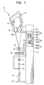
- a unit frame 3 is provided on either side of the winding unit 1 and a winding unit body 4 that winds yarn from a yarn supply bobbin 5 (yarn supply winding body) to a winding bobbin 8 (winding body) is provided on the side of the unit frame 3.
- the winding unit body 4 comprises a bobbin tray mechanism 6 in the lower end part of the winding unit body 4 that keeps the posture of the yarn supply bobbin 5 upright, and a cradle 9 (winding tube support means) in the upper end part of the winding unit body 4 that supports the winding bobbin 8 so as to rotate.
- a yarn detection sensor 10 that detects whether or not a yarn 7 is existed in a detection area, a tensor 11 (tension application unit) that applies a predetermined tension to the yarn 7, a yarn splicing device 14 that splices the yarn ends on the winding bobbin 8 side and the yarn supply bobbin 5 side in breaking yarn, a slab catcher 12 (yarn thickness detector) that detects the defective of the yarn 7 and cuts it, a traverse fulcrum guide 13 that becomes a traverse fulcrum of the yarn 7, and a traverse drum 15 that rotates a winding bobbin 8 and traverses the yarn 7 are provided between the bobbin tray mechanism 6 and the cradle 9, in the order named from the bobbin tray mechanism 6 side.
- a traverse groove 15a for traversing the yarn 7 is formed in the peripheral surface of the traverse drum 15.
- the cradle 9 that supports the winding bobbin 8 is disposed above the traverse drum 15, and presses the winding bobbin 8 to the traverse drum 15 direction in a predetermined pressure.
- the winding bobbin 8 is rotated by the frictional engagement when the traverse dram 15 is rotated and the yarn 7 is rewound to the winding bobbin 8 with being traversed by the traverse drum 15, the winding bobbin 8 around which the yarn 7 in a predetermined length is wound can be produced.
- the transmission pipe 17 sucks and grasps the yarn end on the yarn supply bobbin 5 side after cutting yarn, and rotates so as to make the yarn end pass in front of the yarn splicing device 14, so that the yarn end that is sucked and grasped may be introduced to the yarn splicing device 14.
- a suction mouth 18, that is the winding-side yarn end acquisition guide member grasping the yarn end on the winding bobbin 8 side and guiding it to the yarn splicing device 14, is provided in the unit frame 3.
- the suction mouth 18 sucks and grasps the yarn end on the winding bobbin 8 side after breaking yarn, and rotates so as to make the yarn end pass in front of the yarn splicing device 14, so that the yarn end that is sucked and grasped may be introduced to the yarn splicing device 14.
- the unit frame 3 supports the respective members comprising the winding unit body 4.
- an operation check device 20 having a function of making the operator check the operational condition by activating the input/output equipment of the winding unit body 4 individually, is provided in the unit frame 3.
- the input/output equipment includes an input system (input equipment) and an output system (output equipment).
- the input system is connected to an input port of a unit controller 21 such as the yarn detection sensor 10 and the various types of switches, and has a function of outputting the status signal to the unit controller 21.
- the output system is connected to the output port of the unit controller 21 such as a traverse drum drive motor, a suction mouth drive motor (yarn splicing cam drive motor), and an indicator (LED), and causes automatism such as rotation and lighting, etc. by the operational signal from the unit controller 21.
- a specific equipment number and / or code is added to the input/output equipment, and for example, the code "A0 ⁇ BF" is set in the input system, and the code "C0 ⁇ DF" is set in the output system.
- the operation check device 20, comprising a programmable controller connected to the input/output equipment of the winding unit body 4, includes the unit controller 21 having a plurality of input/output ports, and an operation panel 22 connected to the unit controller 21 so as to input and output the various signals.
- the unit controller 21 comprises an operation part 23 that is capable of storing and executing various programs, an input/output part 24 that is connected to the winding unit body 4 and the operation panel 22 so as to input and output signal, and a communication part 25 so as to communicate with the machine control unit 2 through a telecommunication cable 26.
- the telecommunication cable 26 is provided commonly to a plurality of the unit controllers 21, and the data communication can be implemented between one machine control unit 2 and a plurality of the unit controllers 21 through the common telecommunication cable 26.
- the operation part 23 is capable of executing a program (an operation check drive means 41) that fulfills the operation check drive function for activating the output equipment chosen by a display switch part 33 based on the drive operation of an operation switch 34, and also executing a program (a display control unit 42) that fulfills the display control function that controls display status of an operation check indicator 31 based on the input signal from the input equipment chosen by the display switch part 33.
- the unit controller 21 has a memory part (not shown in the drawings) that stores the relation between the equipment number or code and the equipment (input/output port) in the input equipment and the output equipment. Therefore, when the equipment number or code is chosen in the display switch part 33 (choice means), the equipment (input/output port) to be subject of operation check can be specified. Moreover, the relation between the equipment number or code and the equipment can be set from the machine control unit 2 to the unit controller 21 through the telecommunication cable 26. Thus, when operating on the machine control unit 2 side, the relation can be set in a plurality of the unit controllers 21 together.
- the operation panel 22 connected to the input/output part 24 is provided in the upper end part of the front surface of the unit frame 3.
- the upper end part of the front surface of the unit frame 3 is tilted gradually to the backside from the lower part to the upper part.
- the operation check display part 32 has a high order indicator 32a and a low order indicator 32b.
- the indicators 32a and 32b comprising a seven segment LED, are capable of displaying the input system equipment number or code "A0 ⁇ BF" and the output system equipment number or code "C0 ⁇ DF" in the input/output equipment.
- the operation check display part 32 can be comprised so as to show the equipment number on the liquid crystal display. In this case, a specific name of the input/output equipment can be displayed directly.
- the display switch part 33 is disposed in the vicinity of the operation check display part 32.
- the display switch part 33 is disposed in the vicinity of the lower part of the operation check display part 32, and the operator can easily switch the display switch part 33 while seeing the display content of the operation check display part 32.
- the display switch part 33 has a high order display switch 33a and a low order display switch 33b, comprising a tact switch, etc..
- the respective switches 33a and 33b are provided in response to the respective indicators 32a and 32b, and the numerical value on the display (hexadecimal numeral display) of the respective indicators 32a and 32b can be counted up by pressing the switch.
- the operation switch 34 disposed in the lower part of the display switch part 33, has an operation plate 34a on which the letters "ON” and "OFF” are put, and a switch grip part 34b that is disposed in the operation plate 34a and is capable of switching to the "ON” and “OFF” positions.
- the switch grip part 34b of the operation switch 34 is rotated and switched from the "OFF" display position to the "ON" display position, the objective output equipment (the output equipment chosen in the operation check display part 32) can be switched to operation status in checking the operation of the output equipment. Therefore, as illustrated in the drawings, when the operation switch 34 has a turnable switch grip part 34b, the operator can surely and easily recognize the status of the operation switch 34 based on the angle of the switch grip part 34b.
- the operation switch 34 can have the press-type switch grip part, instead of the turnable one. In case of having the press-type switch grip part, the output equipment can be switched to ON status and OFF status alternately, every time the operation switch 34 is pushed.
- a mode valid/invalid switch 38 is disposed in the side (right side in the drawing) of the display switch part 33.
- the mode valid/invalid switch 38 comprising a single dip switch, is capable of switching the operation mode set by the machine control unit 2 to be valid or invalid.
- the operation check indicator 31 is embedded in the operation switch 34.
- the operation check indicator 31, comprising a high-intensity LED, etc., switches operation status of input equipment by the control of the unit controller 21 and announces the status to the operator. More specifically, if the yarn detection sensor 10 is designated as the object for operation check, the operation check indicator 31 lights up when detecting the yarn 7, and the operation check indicator 31 lights off when not detecting the yarn 7. Additionally, though the operation check indicator 31 announces the status of the input equipment to the operator by the lighting, the status of the input equipment may be announced to the operator by switching the display color of the lighting.
- the winding unit 1 comprised as described above has specific unit numbers (m1 ⁇ mn) respectively.
- the machine control unit 2 connected to the winding unit 1 through the common telecommunication cable 26, chooses a winding unit 1 by the unit number, and has a winding unit choice function for changing the setting of the operation mode in the chosen one or a plurality of the winding unit 1 by remote control. More specifically, when the operator conduct a predetermined operation to the machine control unit 2, the operation mode of the necessary winding unit 1 can be set or changed.
- the machine control unit 2 has an operation mode set means 2a that is capable of choosing any operation mode from a plurality of the operation modes including the operation check mode.
- the machine control unit 2 has a display device (not shown in the drawings) and a list display function that is capable of displaying the relation between the equipment number or code and the output equipment.
- the operation switch 34 in the winding unit 1 to be subject to operation check is in halt condition (OFF status) and the winding is stopped.
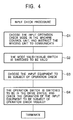
- the mode signal including data of the output operation check mode is transmitted to the respective winding units 1 through the telecommunication cable 26 by issuing the communication instruction after the operator chooses the output operation check mode from the operation mode in the machine control unit 2. Then, if the operator does not designate the unit number, the mode signal from the machine control unit 2 is received by the whole winding units 1 as the winding unit 1 is not chosen. Moreover, if the unit number is designated, only the winding unit 1 corresponding to the unit number receives the mode signal. Consequently, the output operation check mode is temporarily set in the whole or a part of the winding unit 1 that receives the mode signal (S1).
- the mode valid/invalid switch 38 is set to be invalid so as to make the setting by the mode signal invalid even if receiving the mode signal from the machine control unit 2.
- the winding unit 1 is only set to be in the output operation check mode temporarily and can continue the normal winding operation if not the mode valid/invalid switch 38 is valid.
- the operator is moved to the winding unit 1 that the operation check is going to be carried out, and the mode valid/invalid switch 38 provided in the operation panel 22 of the winding unit 1 is switched to be in the valid status (S2).
- the temporary setting of the output operation check mode is canceled in the winding unit 1, and the winding unit 1 is switched to be capable of receiving the signal from the operation switch 34 and the display switch part 33 of the operation panel 22.
- the winding unit 1 is operated by switching the high order display switch 33a and the low order display switch 33b in the display switch part 33.
- the high order indicator 32a and the low order indicator 32b of the operation check display part 32 switch the display of the equipment number and code, accompanied by the switch operation of the respective switches 33a and 33b. Therefore, the operator can choose the output equipment to be subject to operation check while watching the display of the operation check display part 32 actually (S3). Additionally, the operator can see the list showing the relation of the equipment number or code and the output equipment on display in the machine control unit 2.
- the output equipment chosen in the display switch part 33 is activated by rotating the operation switch 34 from the OFF position to the ON position and switching the operation. If the output equipment is activated normally, the output equipment is determined to be activated normally after the operator checks the operation status of the output equipment visually. Meanwhile, if the output equipment is not activated or activated abnormally, the output equipment is determined to have a problem in the output equipment itself or a connection problem between the output equipment and the unit controller 21 (S4). After that, if existing the output equipment that carries out the operation check continuously, the output equipment is chosen in the display switch part 33 and the operation of the output equipment is checked by rotating the operation switch 34 and switching the operation as described above.
- the operator chooses the input operation check mode from the operation mode in the machine control unit 2, and the mode signal including the data of the input operation check mode is transmitted to the respective winding units 1 through the telecommunication cable 26 by carrying out the communication instruction. Then, if the operator does not designate the unit number, the mode signal from the machine control unit 2 is received by the whole winding units 1 as the winding unit 1 is not chosen. Moreover, if the unit number is designated, only the winding unit 1 corresponding to the unit number receives the mode signal. The input operation check mode is going to be set in the whole or a part of the winding unit 1 that receives the mode signal (G1).
- the operator is moved to the winding unit 1 that carries out the operation check, and switches the mode valid/invalid switch 38 provided in the operation panel 22 in the winding unit 1 to be in the valid status (G2).
- the temporary setting of the input operation check mode is canceled in the winding unit 1, the winding unit 1 can receive the signal from the display switch part 33 of the operation panel 22, and the operation check indicator 31 may be switched to light up if the input equipment to be subject of operation check is made to be in the operation status.
- the operation of the high order display switch 33a and the low order display switch 33b in the display switch part 33 is switched.
- the high order indicator 32a and the low order indicator 32b of the operation check display part 32 switches the display of the equipment number and code, accompanied by switching the operation the respective switches 33a and 33b. Therefore, the operator can choose the input equipment to be subject of operation check while watching the display of the operation check display part 32 actually (G3). Additionally, the operator can refer to the list showing the relation between the equipment number or code and the input equipment on display in the machine control unit 2.
- the chosen input equipment is operated so as to be in the operation status. For example, if the yarn detection sensor 10 is chosen as the input equipment to be subject of operation check, the check member such as the yarn is disposed in the check area of the yarn detection sensor 10. If the input equipment is activated normally, the operation check indicator 31 lights up, which shows the operation status of the input equipment, so that the input equipment is determined to be activated normally after the operator checks the display status visually. Meanwhile, if the operation check indicator 31 does not light up, the input equipment is determined that there is a problem in the input equipment itself or there is a connection problem between the input equipment and the unit controller 21 (G4). After that, if existing the input equipment that carries out the operation check continuously, the input equipment is chosen in the display switch part 33, and the input equipment is operated so as to be in the operation status and the display status of the operation check indicator 31 is checked as described above.
- the yarn winding machine in the preferred embodiment of the present invention comprises a plurality of the winding units 1 that are laid side by side, and is capable of checking operation while choosing the input/output equipment of the respective winding units 1 through the unit controller 21.
- the respective winding units 1 comprises the display switch part 33 (output equipment choice means) that is capable of choosing the output equipment to be subject of operation check in the input/output equipment, in the output operation check mode, and the operation switch 34 (operation switch means) that is capable of switching the operation for activating and stopping and drives the output equipment.
- the unit controller 21 is comprised of having the operation part 23 (the operation check drive means 41) that is capable of executing the program which activates the output equipment chosen by the display switch part 33, based on the drive operation of the operation switch 34.
- the output equipment are an electronic valve in the nozzle for untwisting yarn in the yarn splicing device 14, an electromagnetic valve in the nozzle for twisting yarn in the yarn splicing device 14, an actuator for exchanging bobbin, a motor for splicing yarn, a motor for driving the transmission pipe 17, and the indicator (LED), etc.
- the output operation check mode if the operator operates display switch part 33 and chooses the output equipment, the output equipment is subject to operation check, and only the output equipment to be subject of operation check can be activated by the operation switch 34.
- the operation status can be checked by the movement of the rotation, etc. of the motor, etc. in the output equipment. Consequently, even if a series of operations that the portable check tool is connected to the winding unit 1 for establishing communication and the check is carried out by operating the portable check tool, the output equipment of the respective winding units 1 can be easily checked by the simple operation of the display switch part 33 and the operation switch 34 of the winding unit 1, so that the yarn winding machine can be checked completely in short time.
- the respective winding units 1 of the yarn winding machine in the preferred embodiment of the present invention comprises the display switch part 33 that is capable of choosing the operation by switching the input equipment to be subject of operation check in the input/output equipment and the operation check indicator 31 for announcing the operation status of the chosen input equipment, in the input operation check mode.
- the unit controller 21 is comprised of having the operation part 23 (display control unit 42) that is capable of executing the program of controlling the display status of the operation check indicator 31 based on the input signal from the input equipment (the signal corresponding to the operation status of the input equipment) chosen by the display switch part 33, as well as the yarn detection sensor 10 (yarn existence detector).
- the input equipment are a traverse detector (photoelectric sensor) and an origin detector (photoelectric sensor) for yarn splicing cam that detect that the yarn is traversed, a specific angle detector (photoelectric sensor) for yarn splicing cam, a balloon control member detector, an operation start detector (micro switch), an origin detector (photoelectric sensor) of the transmission pipe 17, and the other controllers (such as the driver for dram motor and / or the driver for drive motor of the hairiness control unit).
- the input operation check mode if the operator chooses the input equipment such as the sensor by the operation of the display switch part 33, the input equipment is subject to operation check, and the input equipment to be subject of operation check can be associated with the operation check indicator 31.
- the operation status can be checked by the display of lighting the operation check indicator 31 that is activated in response to the input of the input equipment. Consequently, the respective winding units 1 can be checked by the simple operation of the display switch part 33 and the operation check indicator 31 provided in the winding unit 1, so that the yarn winding machine can be checked completely in short time.
- the preferred embodiment of the present invention describes the yarn winding machine wherein the relation of the unit controller 21 and the winding unit body 4 is one-one, however the example is not confined to this, and the relation of the unit controller 21 and the winding unit body 4 may be one to two, or one to N. More specifically, the yarn winding machine is capable of controlling a plurality of the winding unit body.
- the operation check indicator 31 that announces the operation status by lighting it on or off is illustrated as an example in the preferred embodiment of the present invention, however the device is not limited to the operation check indicator 31, and the buzzer can be used for announcing the operation status by voice.
- the respective winding units comprise the output equipment choice means that is capable of switching operation of the output equipment to be subject of operation check and an operation switch means that is capable of controlling the switch for driving and stopping the winding units
- the unit controller comprises an operation check drive means that is capable of activating an output equipment chosen by the output equipment choice means, according to the operation of driving the operation switch means.
- the output equipment is subject to operation check, and only the output equipment to be subject of operation check can be activated by the operation switch means.
- the operation status can be checked by the movement such as rotation, etc. of the motor, etc. of the output equipment. Consequently, even if not carrying out a series of conventional operations that the portable check tool is connected to the winding unit for establishing communication and the check is carried out by operating the portable check tool, the output equipment of the respective winding units can be easily checked by the simple operation of the output equipment choice means and the operation switch means of the winding unit, so that there is an effect that the yarn winding machine can be checked completely in short time.
- the respective winding units comprise an input equipment choice means that is capable of switching operation of the input equipment to be subject of operation check and an operation check indicator
- the controller unit comprises a display control means that controls the display status of the operation check indicator based on the input signal from the input equipment chosen by the input equipment choice means.
- the input equipment such as sensor by operating the choice means
- the input equipment is subject to operation check
- the input equipment to be subject of operation check can be associated with the operation check indicator.
- the operation status can be checked by the display of lighting, etc. of the operation check indicator that is activated in response to the input of the input equipment. Consequently, even if not carrying out a series of conventional operations that the portable check tool is connected to the winding unit for establishing communication and the check is carried out by operating the portable check tool, the input equipment of the respective winding units can be checked easily by the simple operation of the input equipment choice means provided in the winding unit, so that there is an effect that the yarn winding machine can be checked completely in short time.
- the yarn winding machine as in claim 1 or claim 2 has a machine control unit that is connected to the unit controller so as to communicate data, and the machine control unit comprises an operation mode setting means that is capable of choosing the operation check mode for checking operation from a plurality of the operation check mode, and the winding unit is capable of setting in the operation check mode in data communication from the machine control unit to the unit controller.
- the necessary winding unit can be set in the requested operation mode through the unit controller as the machine control unit is connected to the unit controller so as to communicate data. Consequently, even if multiple winding units are existed, the operation mode can be easily switched and set completely in short time.
- the respective winding units comprise a mode valid/invalid switch means that is capable of switching the set operation mode to be valid or invalid.
- the operation switch means can be used as the switch for starting and stopping the production (winding) by the manual operation, etc. when the operation mode is invalid.
- the operation check indicator can be used as the indicator for announcing alarm while winding when the operation mode is kept to be invalid. More specifically, there is an effect that the operation switch means and the operation check indicator can be used for further purposes by having the mode valid/invalid switch means.
Landscapes
- Engineering & Computer Science (AREA)
- Quality & Reliability (AREA)
- Filamentary Materials, Packages, And Safety Devices Therefor (AREA)
- Spinning Or Twisting Of Yarns (AREA)
Abstract
Description
Claims (4)
- A yarn winding machine having a plurality of winding units that are laid side by side, which is capable of checking operation of output equipments of the respective winding units while choosing the output equipments of the winding units with a unit controller,
wherein the respective winding units comprise an output equipment choice means that is capable of switching operation of the output equipment to be subject of operation check and an operation switch means that is capable of controlling the switch for driving and stopping the winding units, and
the unit controller comprises an operation check drive means that is capable of activating output equipment chosen by the output equipment choice means, according to the operation of driving the operation switch means: - A yarn winding machine having a plurality of winding units that are laid side by side, which is capable of checking operation of input equipments of the respective winding units while choosing the input equipments of the winding units with a unit controller,
wherein the respective winding units comprise an input equipment choice means that is capable of switching operation of the input equipment to be subject of operation check and an operation check indicator, and
the controller unit comprises a display control means that controls the display status of the operation check indicator based on the input signal from the input equipment chosen by the input equipment choice means. - A yarn winding machine as in claim 1 or Claim 2, comprising a machine control unit that is connected to the unit controller so as to communicate data,
wherein the machine control unit comprises an operation mode setting means that is capable of choosing an operation check mode for checking operation from a plurality of the operation check modes, and
a winding unit is capable of setting in the operation check mode in data communication from the machine control unit to the unit controller. - A yarn winding machine as in claim 3, wherein the respective winding units comprise a mode valid/invalid switch means that is capable of switching the set operation mode to be valid or invalid.
Applications Claiming Priority (2)
| Application Number | Priority Date | Filing Date | Title |
|---|---|---|---|
| JP2001308746 | 2001-10-04 | ||
| JP2001308746A JP3861644B2 (en) | 2001-10-04 | 2001-10-04 | Yarn winding machine |
Publications (3)
| Publication Number | Publication Date |
|---|---|
| EP1300358A2 true EP1300358A2 (en) | 2003-04-09 |
| EP1300358A3 EP1300358A3 (en) | 2003-09-10 |
| EP1300358B1 EP1300358B1 (en) | 2007-04-04 |
Family
ID=19128005
Family Applications (1)
| Application Number | Title | Priority Date | Filing Date |
|---|---|---|---|
| EP20020021474 Expired - Lifetime EP1300358B1 (en) | 2001-10-04 | 2002-09-25 | Yarn winding machine |
Country Status (3)
| Country | Link |
|---|---|
| EP (1) | EP1300358B1 (en) |
| JP (1) | JP3861644B2 (en) |
| DE (1) | DE60219260T2 (en) |
Cited By (5)
| Publication number | Priority date | Publication date | Assignee | Title |
|---|---|---|---|---|
| EP1481932A1 (en) * | 2003-05-30 | 2004-12-01 | Murata Kikai Kabushiki Kaisha | Yarn winder |
| WO2007045346A1 (en) * | 2005-10-19 | 2007-04-26 | Oerlikon Textile Gmbh & Co. Kg | Process for bi-directional data transmission between one or more textile machines |
| DE102006045237A1 (en) * | 2006-09-26 | 2008-04-03 | Oerlikon Textile Gmbh & Co. Kg | Winding machine comprises multiple winding points operated independently, and winding point calculator is provided, which is assigned to winding points |
| EP2272781A3 (en) * | 2009-07-09 | 2011-09-14 | Murata Machinery, Ltd. | Yarn Winding Machine and Textile Machine |
| CN103010840A (en) * | 2011-09-20 | 2013-04-03 | 村田机械株式会社 | A yarn winding apparatus and an operation original location adjusting method |
Families Citing this family (3)
| Publication number | Priority date | Publication date | Assignee | Title |
|---|---|---|---|---|
| JP5202983B2 (en) * | 2008-02-15 | 2013-06-05 | 日本発條株式会社 | Parking device and control program |
| DE102010034971A1 (en) | 2010-08-20 | 2012-02-23 | Oerlikon Textile Gmbh & Co. Kg | textile machine |
| JP2012218915A (en) | 2011-04-12 | 2012-11-12 | Murata Machinery Ltd | Automatic winder |
Family Cites Families (8)
| Publication number | Priority date | Publication date | Assignee | Title |
|---|---|---|---|---|
| DE3928831A1 (en) * | 1989-08-31 | 1991-03-07 | Schlafhorst & Co W | Multistation textile machine prepn. - uses program down-load between central and control computers |
| US5224047A (en) * | 1989-10-03 | 1993-06-29 | Murata Kikai Kabushiki Kaisha | Maintenance monitoring apparatus for automatic winder |
| JPH06127825A (en) * | 1992-10-16 | 1994-05-10 | Murata Mach Ltd | Part control system for textile machine |
| DE4335459C2 (en) * | 1993-10-18 | 1999-12-02 | Rieter Ingolstadt Spinnerei | Spinning station fault notifier and qualifier |
| DE19505023B4 (en) * | 1995-02-15 | 2005-08-04 | Saurer Gmbh & Co. Kg | Textile machine with a central control device and decentralized control devices at the workstations |
| JP2000198622A (en) * | 1999-01-08 | 2000-07-18 | Toray Eng Co Ltd | Yarn winding machine |
| DE19907684B4 (en) * | 1999-02-23 | 2007-04-12 | Saurer Gmbh & Co. Kg | Textile machine with processors at the workstations |
| DE19930714C5 (en) * | 1999-07-02 | 2015-04-09 | Rieter Ingolstadt Gmbh | Textile machine with a variety of similar jobs |
-
2001
- 2001-10-04 JP JP2001308746A patent/JP3861644B2/en not_active Expired - Lifetime
-
2002
- 2002-09-25 EP EP20020021474 patent/EP1300358B1/en not_active Expired - Lifetime
- 2002-09-25 DE DE2002619260 patent/DE60219260T2/en not_active Expired - Lifetime
Cited By (10)
| Publication number | Priority date | Publication date | Assignee | Title |
|---|---|---|---|---|
| EP1481932A1 (en) * | 2003-05-30 | 2004-12-01 | Murata Kikai Kabushiki Kaisha | Yarn winder |
| CN100336709C (en) * | 2003-05-30 | 2007-09-12 | 村田机械株式会社 | Yarn Winder |
| WO2007045346A1 (en) * | 2005-10-19 | 2007-04-26 | Oerlikon Textile Gmbh & Co. Kg | Process for bi-directional data transmission between one or more textile machines |
| US8033090B2 (en) | 2005-10-19 | 2011-10-11 | Oerlikon Textile Gmbh & Co. Kg | Method for the bidirectional transmission of data between one or more textile machines |
| CN101287665B (en) * | 2005-10-19 | 2012-04-25 | 欧瑞康纺织有限及两合公司 | Method for bidirectional data transfer between one or more textile machines |
| DE102006045237A1 (en) * | 2006-09-26 | 2008-04-03 | Oerlikon Textile Gmbh & Co. Kg | Winding machine comprises multiple winding points operated independently, and winding point calculator is provided, which is assigned to winding points |
| CN101152937B (en) * | 2006-09-26 | 2012-08-08 | 欧瑞康纺织有限及两合公司 | Winding machine |
| EP2272781A3 (en) * | 2009-07-09 | 2011-09-14 | Murata Machinery, Ltd. | Yarn Winding Machine and Textile Machine |
| CN103010840A (en) * | 2011-09-20 | 2013-04-03 | 村田机械株式会社 | A yarn winding apparatus and an operation original location adjusting method |
| CN103010840B (en) * | 2011-09-20 | 2016-12-21 | 村田机械株式会社 | Yarn reeling device and action origin position method of adjustment |
Also Published As
| Publication number | Publication date |
|---|---|
| EP1300358B1 (en) | 2007-04-04 |
| EP1300358A3 (en) | 2003-09-10 |
| JP3861644B2 (en) | 2006-12-20 |
| DE60219260T2 (en) | 2008-01-03 |
| JP2003112854A (en) | 2003-04-18 |
| DE60219260D1 (en) | 2007-05-16 |
Similar Documents
| Publication | Publication Date | Title |
|---|---|---|
| EP1300358B1 (en) | Yarn winding machine | |
| JPH01281266A (en) | Operation control method in fiber machine | |
| JP2011016630A (en) | Textile machine | |
| JP2011016631A (en) | Yarn winder and textile machine | |
| EP2671832B1 (en) | Yarn winding device | |
| EP1481932B1 (en) | Yarn winder | |
| JP3951941B2 (en) | Automatic winder | |
| JP2008212531A (en) | Lower thread remaining amount detection device for sewing machine | |
| JP4149367B2 (en) | Textile machine setting display device | |
| JPH0570040A (en) | Operation control system for automatic winder | |
| JP3084477B2 (en) | Continuous terminal winding machine and its control device | |
| JP2000198622A (en) | Yarn winding machine | |
| EP4321464A1 (en) | Automatic winder | |
| KR100339712B1 (en) | Automatic wire speed and tension control method for wire winding device | |
| JP2011016632A (en) | Yarn winder and textile machine | |
| JP2531390B2 (en) | Automatic winder winding condition setting system | |
| JP3535762B2 (en) | Fishing reel | |
| JP2020000135A (en) | Control device of spool and line exchange attachment type fishing electric reel | |
| JP2010070301A (en) | Textile machine | |
| JPH08299646A (en) | Bobbin winding device | |
| JPH08173672A (en) | Bobbin bobbin winding amount control device | |
| JPH1077160A (en) | Package specifying device | |
| JPH07300278A (en) | Winder control device | |
| EP2096070A2 (en) | Yarn winding device and textile machine including the same | |
| JPH0752135Y2 (en) | Winding machine safety device |
Legal Events
| Date | Code | Title | Description |
|---|---|---|---|
| PUAI | Public reference made under article 153(3) epc to a published international application that has entered the european phase |
Free format text: ORIGINAL CODE: 0009012 |
|
| AK | Designated contracting states |
Kind code of ref document: A2 Designated state(s): AT BE BG CH CY CZ DE DK EE ES FI FR GB GR IE IT LI LU MC NL PT SE SK TR Designated state(s): AT BE BG CH CY CZ DE DK EE ES FI FR GB GR IE IT LI LU MC NL PT SE SK TR |
|
| AX | Request for extension of the european patent |
Extension state: AL LT LV MK RO SI |
|
| PUAL | Search report despatched |
Free format text: ORIGINAL CODE: 0009013 |
|
| AK | Designated contracting states |
Kind code of ref document: A3 Designated state(s): AT BE BG CH CY CZ DE DK EE ES FI FR GB GR IE IT LI LU MC NL PT SE SK TR |
|
| AX | Request for extension of the european patent |
Extension state: AL LT LV MK RO SI |
|
| 17P | Request for examination filed |
Effective date: 20040119 |
|
| AKX | Designation fees paid |
Designated state(s): DE IT |
|
| 17Q | First examination report despatched |
Effective date: 20050404 |
|
| GRAP | Despatch of communication of intention to grant a patent |
Free format text: ORIGINAL CODE: EPIDOSNIGR1 |
|
| GRAS | Grant fee paid |
Free format text: ORIGINAL CODE: EPIDOSNIGR3 |
|
| GRAA | (expected) grant |
Free format text: ORIGINAL CODE: 0009210 |
|
| AK | Designated contracting states |
Kind code of ref document: B1 Designated state(s): DE IT |
|
| REF | Corresponds to: |
Ref document number: 60219260 Country of ref document: DE Date of ref document: 20070516 Kind code of ref document: P |
|
| PLBE | No opposition filed within time limit |
Free format text: ORIGINAL CODE: 0009261 |
|
| STAA | Information on the status of an ep patent application or granted ep patent |
Free format text: STATUS: NO OPPOSITION FILED WITHIN TIME LIMIT |
|
| 26N | No opposition filed |
Effective date: 20080107 |
|
| REG | Reference to a national code |
Ref country code: DE Ref legal event code: R082 Ref document number: 60219260 Country of ref document: DE Representative=s name: PATENTANWAELTE WEICKMANN & WEICKMANN, DE Ref country code: DE Ref legal event code: R082 Ref document number: 60219260 Country of ref document: DE Representative=s name: WEICKMANN & WEICKMANN PATENTANWAELTE - RECHTSA, DE Ref country code: DE Ref legal event code: R082 Ref document number: 60219260 Country of ref document: DE Representative=s name: WEICKMANN & WEICKMANN PATENT- UND RECHTSANWAEL, DE |
|
| PGFP | Annual fee paid to national office [announced via postgrant information from national office to epo] |
Ref country code: DE Payment date: 20200925 Year of fee payment: 19 |
|
| PGFP | Annual fee paid to national office [announced via postgrant information from national office to epo] |
Ref country code: IT Payment date: 20200922 Year of fee payment: 19 |
|
| REG | Reference to a national code |
Ref country code: DE Ref legal event code: R119 Ref document number: 60219260 Country of ref document: DE |
|
| PG25 | Lapsed in a contracting state [announced via postgrant information from national office to epo] |
Ref country code: DE Free format text: LAPSE BECAUSE OF NON-PAYMENT OF DUE FEES Effective date: 20220401 |
|
| PG25 | Lapsed in a contracting state [announced via postgrant information from national office to epo] |
Ref country code: IT Free format text: LAPSE BECAUSE OF NON-PAYMENT OF DUE FEES Effective date: 20210925 |