EP1300206B1 - Metallic inserted member, method of manufacturing metallic inserted member, and metallic cast part - Google Patents
Metallic inserted member, method of manufacturing metallic inserted member, and metallic cast part Download PDFInfo
- Publication number
- EP1300206B1 EP1300206B1 EP01941072A EP01941072A EP1300206B1 EP 1300206 B1 EP1300206 B1 EP 1300206B1 EP 01941072 A EP01941072 A EP 01941072A EP 01941072 A EP01941072 A EP 01941072A EP 1300206 B1 EP1300206 B1 EP 1300206B1
- Authority
- EP
- European Patent Office
- Prior art keywords
- projections
- metal member
- cast
- grooves
- metal
- Prior art date
- Legal status (The legal status is an assumption and is not a legal conclusion. Google has not performed a legal analysis and makes no representation as to the accuracy of the status listed.)
- Expired - Lifetime
Links
- 238000004519 manufacturing process Methods 0.000 title claims description 6
- 229910052751 metal Inorganic materials 0.000 claims description 109
- 239000002184 metal Substances 0.000 claims description 109
- 238000001125 extrusion Methods 0.000 claims description 24
- 230000001788 irregular Effects 0.000 claims description 17
- 230000002093 peripheral effect Effects 0.000 claims description 17
- 238000000034 method Methods 0.000 claims description 12
- 239000000463 material Substances 0.000 claims description 5
- 239000007769 metal material Substances 0.000 claims description 4
- 239000000843 powder Substances 0.000 description 9
- 238000002485 combustion reaction Methods 0.000 description 8
- 238000001816 cooling Methods 0.000 description 6
- 229910000676 Si alloy Inorganic materials 0.000 description 4
- CSDREXVUYHZDNP-UHFFFAOYSA-N alumanylidynesilicon Chemical compound [Al].[Si] CSDREXVUYHZDNP-UHFFFAOYSA-N 0.000 description 4
- 238000009826 distribution Methods 0.000 description 4
- 230000000694 effects Effects 0.000 description 4
- 229910001234 light alloy Inorganic materials 0.000 description 3
- 239000011159 matrix material Substances 0.000 description 3
- 239000002245 particle Substances 0.000 description 3
- IJGRMHOSHXDMSA-UHFFFAOYSA-N Atomic nitrogen Chemical compound N#N IJGRMHOSHXDMSA-UHFFFAOYSA-N 0.000 description 2
- OKTJSMMVPCPJKN-UHFFFAOYSA-N Carbon Chemical compound [C] OKTJSMMVPCPJKN-UHFFFAOYSA-N 0.000 description 2
- PNEYBMLMFCGWSK-UHFFFAOYSA-N aluminium oxide Inorganic materials [O-2].[O-2].[O-2].[Al+3].[Al+3] PNEYBMLMFCGWSK-UHFFFAOYSA-N 0.000 description 2
- 238000007664 blowing Methods 0.000 description 2
- 229910052593 corundum Inorganic materials 0.000 description 2
- 238000004512 die casting Methods 0.000 description 2
- 238000010438 heat treatment Methods 0.000 description 2
- 230000002706 hydrostatic effect Effects 0.000 description 2
- 238000002347 injection Methods 0.000 description 2
- 239000007924 injection Substances 0.000 description 2
- 238000002156 mixing Methods 0.000 description 2
- 239000002994 raw material Substances 0.000 description 2
- 229910000838 Al alloy Inorganic materials 0.000 description 1
- 101100298225 Caenorhabditis elegans pot-2 gene Proteins 0.000 description 1
- 239000004215 Carbon black (E152) Substances 0.000 description 1
- 238000005299 abrasion Methods 0.000 description 1
- 239000010431 corundum Substances 0.000 description 1
- 239000010419 fine particle Substances 0.000 description 1
- 239000007789 gas Substances 0.000 description 1
- 229910002804 graphite Inorganic materials 0.000 description 1
- 239000010439 graphite Substances 0.000 description 1
- 238000001192 hot extrusion Methods 0.000 description 1
- 229930195733 hydrocarbon Natural products 0.000 description 1
- 150000002430 hydrocarbons Chemical class 0.000 description 1
- 239000011261 inert gas Substances 0.000 description 1
- 239000007788 liquid Substances 0.000 description 1
- 239000000203 mixture Substances 0.000 description 1
- 229910052757 nitrogen Inorganic materials 0.000 description 1
- 239000003921 oil Substances 0.000 description 1
- 238000003860 storage Methods 0.000 description 1
- 230000008646 thermal stress Effects 0.000 description 1
- XLYOFNOQVPJJNP-UHFFFAOYSA-N water Substances O XLYOFNOQVPJJNP-UHFFFAOYSA-N 0.000 description 1
- 229910001845 yogo sapphire Inorganic materials 0.000 description 1
Images



Classifications
-
- B—PERFORMING OPERATIONS; TRANSPORTING
- B22—CASTING; POWDER METALLURGY
- B22D—CASTING OF METALS; CASTING OF OTHER SUBSTANCES BY THE SAME PROCESSES OR DEVICES
- B22D19/00—Casting in, on, or around objects which form part of the product
-
- B—PERFORMING OPERATIONS; TRANSPORTING
- B22—CASTING; POWDER METALLURGY
- B22D—CASTING OF METALS; CASTING OF OTHER SUBSTANCES BY THE SAME PROCESSES OR DEVICES
- B22D19/00—Casting in, on, or around objects which form part of the product
- B22D19/0081—Casting in, on, or around objects which form part of the product pretreatment of the insert, e.g. for enhancing the bonding between insert and surrounding cast metal
-
- Y—GENERAL TAGGING OF NEW TECHNOLOGICAL DEVELOPMENTS; GENERAL TAGGING OF CROSS-SECTIONAL TECHNOLOGIES SPANNING OVER SEVERAL SECTIONS OF THE IPC; TECHNICAL SUBJECTS COVERED BY FORMER USPC CROSS-REFERENCE ART COLLECTIONS [XRACs] AND DIGESTS
- Y10—TECHNICAL SUBJECTS COVERED BY FORMER USPC
- Y10T—TECHNICAL SUBJECTS COVERED BY FORMER US CLASSIFICATION
- Y10T428/00—Stock material or miscellaneous articles
- Y10T428/12—All metal or with adjacent metals
- Y10T428/12201—Width or thickness variation or marginal cuts repeating longitudinally
-
- Y—GENERAL TAGGING OF NEW TECHNOLOGICAL DEVELOPMENTS; GENERAL TAGGING OF CROSS-SECTIONAL TECHNOLOGIES SPANNING OVER SEVERAL SECTIONS OF THE IPC; TECHNICAL SUBJECTS COVERED BY FORMER USPC CROSS-REFERENCE ART COLLECTIONS [XRACs] AND DIGESTS
- Y10—TECHNICAL SUBJECTS COVERED BY FORMER USPC
- Y10T—TECHNICAL SUBJECTS COVERED BY FORMER US CLASSIFICATION
- Y10T428/00—Stock material or miscellaneous articles
- Y10T428/12—All metal or with adjacent metals
- Y10T428/12229—Intermediate article [e.g., blank, etc.]
-
- Y—GENERAL TAGGING OF NEW TECHNOLOGICAL DEVELOPMENTS; GENERAL TAGGING OF CROSS-SECTIONAL TECHNOLOGIES SPANNING OVER SEVERAL SECTIONS OF THE IPC; TECHNICAL SUBJECTS COVERED BY FORMER USPC CROSS-REFERENCE ART COLLECTIONS [XRACs] AND DIGESTS
- Y10—TECHNICAL SUBJECTS COVERED BY FORMER USPC
- Y10T—TECHNICAL SUBJECTS COVERED BY FORMER US CLASSIFICATION
- Y10T428/00—Stock material or miscellaneous articles
- Y10T428/12—All metal or with adjacent metals
- Y10T428/12229—Intermediate article [e.g., blank, etc.]
- Y10T428/12264—Intermediate article [e.g., blank, etc.] having outward flange, gripping means or interlocking feature
-
- Y—GENERAL TAGGING OF NEW TECHNOLOGICAL DEVELOPMENTS; GENERAL TAGGING OF CROSS-SECTIONAL TECHNOLOGIES SPANNING OVER SEVERAL SECTIONS OF THE IPC; TECHNICAL SUBJECTS COVERED BY FORMER USPC CROSS-REFERENCE ART COLLECTIONS [XRACs] AND DIGESTS
- Y10—TECHNICAL SUBJECTS COVERED BY FORMER USPC
- Y10T—TECHNICAL SUBJECTS COVERED BY FORMER US CLASSIFICATION
- Y10T428/00—Stock material or miscellaneous articles
- Y10T428/12—All metal or with adjacent metals
- Y10T428/12451—Macroscopically anomalous interface between layers
-
- Y—GENERAL TAGGING OF NEW TECHNOLOGICAL DEVELOPMENTS; GENERAL TAGGING OF CROSS-SECTIONAL TECHNOLOGIES SPANNING OVER SEVERAL SECTIONS OF THE IPC; TECHNICAL SUBJECTS COVERED BY FORMER USPC CROSS-REFERENCE ART COLLECTIONS [XRACs] AND DIGESTS
- Y10—TECHNICAL SUBJECTS COVERED BY FORMER USPC
- Y10T—TECHNICAL SUBJECTS COVERED BY FORMER US CLASSIFICATION
- Y10T428/00—Stock material or miscellaneous articles
- Y10T428/12—All metal or with adjacent metals
- Y10T428/12993—Surface feature [e.g., rough, mirror]
Definitions
- the present invention relates to a metal member to be cast-wrapped by a metal cast article, a method for manufacturing the metal member to be cast-wrapped and a metal cast article including the metal member to be cast-wrapped.
- a light metal member to be cast-wrapped by a light metal cast article which has a rough uneven outer surface formed by shot-blast blowing hard coarse pyramidal or sharp grains against the outer surface, has been known ( Japanese Laid-open Patent Publication Hei 10-94867 ).
- an outer surface of the hard coarse grain is required to have a sharp edge, in order to make the outer surface of the light metal member rough.
- the hard coarse grain is a high-class corundum particle which is a fragile hard material with broken sharp edge, it is inevitable that the hard coarse grain becomes fine by the shot-blast. Therefore, in order to use the hard coarse grains after the shot-blast repeatedly, it is necessary that the hard coarse grains made fine by the shot-blast are separated and removed continuously to maintain a predetermined distribution of the grain size. This administration of the grain size is complicated.
- Projections of a rough surface formed on the light metal member to be cast-wrapped may be melted by large heat capacity of the cast-wrapping light metal and metallurgically combined with the cast-wrapping light metal.
- the metallurgically combined portion is a part of the surface of the light metal member to be cast-wrapped and the projection of the rough surface is tapered, so that mechanical combining force between the light metal member to be cast-wrapped and the cast-wrapping light metal is low. Therefore, when a force for mutually separating the light metal member to be cast-wrapped and the cast-wrapping light metal acts owing to difference of thermal expansion of them, a crack is apt to be produced at a boundary portion between them to remarkably lower heat transfer between them.
- EP-A-0919715 discloses a cylinder liner cast into a cylinder block.
- the outer surface of the cylinder liner is provided with circumferentially extending machined grooves with parallelogram or trapezoidal cross-section.
- the preamble of claim 1 is based on this document.
- smooth grooves are provided in the longitudinal direction of a cylinder liner body and longitudinal smooth projections (ribs) extend between the grooves.
- the liner is not disclosed as an extruded member.
- JP 49 044 857 B1 the projections and grooves extend in the axial direction of a cylindrical element.
- This cylindrical element is not extruded but formed from flat sheet provided with projections and grooves and bent into a cylinder shape afterwards.
- the present invention relates to an improvement of the customary metal member to be cast-wrapped overcoming the above difficulties.
- the present invention provides a metal member that has been cast-wrapped by a metal cast article, wherein said surface of said metal member cast-wrapped by said metal cast article is an irregular surface with projections projecting therefrom, and a maximum width of said projections at a tip end portion is wider than a maximum width of the projections at a base portion, characterized in that said metal member is an extruded member having grooves extending in the extruding direction and said projections are formed between said grooves as irregularly shaped projections separated from each other in the extrusion direction, wherein said projections are lined up in rugged lines extending in the extrusion direction, wherein adjacent rugged lines are separated from each other by the grooves, and the grooves have no such projections, wherein said projections are metallurgically combined with the cast-wrapping material.
- the cast wrapping molten metal surrounds the projection of the metal member to be cast-wrapped covering a wide area and the surface of the projection is sufficiently heated by heat of the molten metal to be metallurgically combined with the cast-wrapping metal surely.
- the projection Since the maximum width of the projection at the tip end portion is wider than the maximum width of the projection at the base portion, the projection is combined with the cast-wrapping metal mechanically strongly by hook effect, so that a crack is hardly produced at a boundary portion between them and a high heat transfer is obtained.
- the metal member to be cast-wrapped has an irregular uneven surface, surface area of the projection of the metal member to be cast-wrapped is increased to promote the metallurgical combination and the metal member to be cast-wrapped is combined with the cast-wrapping metal more strongly.
- the metal member to be cast-wrapped is an extruded member having a smooth grooves directed in a direction of extruding and irregular shaped projections disposed between the grooves , and the irregular shaped projections are formed when the metal member is extruded.
- the metal member to be cast-wrapped having projections can be mass-produced efficiently and at a low cost.
- At least a part of the tip end portion of the projection may be formed in a tapering sharp shape. Since the tip end portion of the projection is sharp, heat mass is little and the projection can be metallurgically combined with the cast-wrapping metal perfectly.
- a side of the irregular projection near an extrusion starting end may be wide and high and a side of the irregular projection near an extrusion completing end may be narrow and low. Drag resistance of the metal member to be cast-wrapped against the cast-wrapping metal in the extruding direction becomes larger remarkably.
- the metal member to be cast-wrapped may be a hollow cylindrical body.
- a sleeve of an internal combustion engine for example, can be manufactured easily and very strong tight combination of a block and the sleeve can be obtained.
- the metal member is cylindrical and has an outer surface formed with the projections, the projections are arranged in axially extending rows and separated circumferentially at regular intervals through the grooves, and wherein the projections are separated from each other in the axial direction and tip end portions of the projections are bent laterally
- the tapered tip end of the projection of the cylindrical metal member to be cast-wrapped is metallurgically combined with the cast-wrapping metal sufficiently, and the whole projection is heated by molten metal storage effect of the undercut portion to promote the metallurgical combination. Further, movement of the cast-wrapping metal in radial and circumferential direction is restrained by a bent portion having the undercut portion to strengthen combining force and adhering force owing to mechanical combination.
- the metal member is cylindrical, wherein the metal member has an outer surface formed with the projections, the projections are arranged in axially extending rows and separated circumferentially at regular intervals through the grooves, and wherein the projections are separated from each other in the axial direction and tip end portions of the projections are bent in axial direction.
- Adhesion and combining force in axial direction of the cylinder is improved to restrain mutual slipping in the axial direction between the cylindrical metal member to be cast-wrapped and the cast-wrapping metal and fix them to each other firmly. Owing to improvement of adhesion, heat transfer, cooling performance and knocking resistance are improved.
- the projections formed on the outer surface of the cylindrical metal member to be cast-wrapped are arranged axially in rows and arranged circumferentially at regular intervals through grooves, adhesion and combining force in axial direction of the cylinder is improved by the rows of the projections and the grooves intervening between the rows of the projections, mutual slipping in the axial direction between the cylindrical metal member to be cast-wrapped and the cast-wrapping metal is restrained, and they are fixed to each other firmly. Therefore, owing to improvement of adhesion, heat transfer, cooling performance and knocking resistance are improved.
- the groove between the rows of projections improves running of molten metal so that quality of the cast product is improved.
- the projections formed on the outer surface of the metal member to be cast-wrapped may be arranged axially at irregular intervals and may be not aligned circumferentially. Mutual slipping between the cylindrical metal to be cast-wrapped and the cast-wrapping metal in circumferential direction, as well as in axial direction, is restrained, adhesion and combining force between the cylindrical metal to be cast-wrapped and the cast-wrapping metal is improved more, and cooling performance and knocking resistance are further improved.
- the present invention provides further, a method for manufacturing a cylindrical metal member having an irregular outer surface with projections and cast-wrapping said cylindrical metal member by a metal cast article; comprising: preparing a die having an inner peripheral surface formed with longitudinal grooves of depth H and width W, relation between a maximum depth H MAX and a minimum width W MIN of the groove being set as H MAX / W MIN 1.5; inserting a cylindrical metal material in said die; hot-extruding said cylindrical metal material to obtain the cylindrical metal member having an outer surface with projections, wherein the inner peripheral surface of the die forms grooves provided in the cylindrical metal member and extending in the extruding direction, and forms said projections as irregularly shaped projections separated from each other in the extrusion direction between said grooves of said cylindrical metal member owing to a large resistance to contact with the grooves of the die, such that a maximum width of said projections at a tip end portion is wider than a maximum width of the projections at a base portion, and said projections are lined up in rugged lines
- the minimum width W MIN of the groove may be set as W MIN 1.3 mm. Much more portions bent in axial direction can be produced on the outer surface of the cylindrical metal member to be cast-wrapped.
- Relation between a minimum inner diameter d and a total inner peripheral length L of a cross-section of the die may be set as L / d ⁇ ⁇ 1.5.
- the portions bent in axial direction can be produced on the outer surface of the cylindrical metal member to be cast-wrapped more surely.
- the metal member to be cast-wrapped may be made in a hollow cylindrical body.
- the metal member to be cast-wrapped is applied to a sleeve of an internal combustion engine, combination and adhesion between a block and the sleeve and cooling nature are improved so that an internal combustion engine of high reliability can be obtained.
- molten light alloy 1 containing Al-73 %, Si-17 %, Fe-5 %, Cu-3.5 %, Mg-1 % and Mn-0.5 % (weight %) is charged in a crucible 3 from a pot 2.
- the molten light alloy drops through an opening provided at a bottom of the crucible.
- the molten light alloy becomes fine particles and is rapidly cooled by air or inert gas blown at a high speed from nozzles 4 surrounding the opening, and matrix sub-/per-eutectic aluminum silicon alloy powder 5 is formed (atomizing process).
- the matrix sub-/per-eutectic aluminum silicon alloy powder 5 is charged into a mixing vessel 6 together with alumina powder giving abrasion resistance and graphite powder giving self-lubricating nature ( Fig. 1b ). Then, the mixing vessel 6 is closed tight and rotated about a horizontal axis 7 so that the powder is mixed uniformly and bullet raw material powder 8 is obtained.
- the bullet raw material powder 8 is charged into a cylindrical rubber bag 10 in which a core 9 having a diameter corresponding to a diameter of a cylinder bore of an internal combustion engine is disposed.
- the cylindrical rubber bag 10 is housed in a cylindrical pressure vessel 12 having upper and lower lids 11.
- a liquid such as water is charged in the cylindrical pressure vessel 12 and given pressure of 1.6 GPa to preparatively form a hollow cylindrical bullet 13 ( Fig. 1d ) having a uniform density distribution and a density ratio of about 70 % (cold hydrostatic pressure forming process).
- the hollow cylindrical bullet 13 is put in a heating furnace (not shown) and preheated and degassed under nitrogen atmospheric gas ( Fig. 1e ). Then, the hollow cylindrical bullet 13 is charged in a container 15 of a hot extrusion apparatus 14 shown in Fig. 1f .
- a mandrel 16 is inserted in a central hole of the hollow cylindrical bullet 13.
- the mandrel 16 is fixed so that a front end of the mandrel 16 is positioned on a extrusion side of a die 17 fixed to the container 15.
- a front end of a main ram 18 is touched to a back side of the hollow cylindrical bullet 13 so that the hollow cylindrical bullet 13 is extruded when the main ram 18 moves in a extruding direction X.
- the extruded hollow cylindrical bullet 13 is cut by mechanical work to obtain sleeves 19 of predetermined length ( Fig. 1g ).
- the die 17 has a circular opening 17a having an inner diameter of 94.3 mm, and on the peripheral surface of the opening 17a are formed grooves 17b of width W and depth H arranged circumferentially uniformly.
- peripheral length of the groove 17b is long, the hollow cylindrical bullet 13 is subjected to a large resistance owing to contact with the grooves 17b of the die 17 when the bullet 13 passes through the grooves 17b, so that the above-mentioned tears are produced.
- the "tear producing rate" in Fig. 5 means a ratio of a number of the projecting lines on which irregular rugged lines are formed by the tear to the total number of the projecting lines on the sleeve 19. In the samples 1 and 2, the tear producing rate is more than 70 % and good, therefore H/W more than 1.9 is desirable.
- wide and high portions 20a (irregularely shaped portions 20a) and narrow and low portions 20b are arranged irregularly in direction of extrusion, and in the wide and high portion 20a, a tip end portion is wider than a base portion near a surface of a groove 21 of the sleeve 19 (the base portion is constricted as shown in Figs. 10 and 11 ). Further, the surface of the wide and high portions 20a is formed in an irregular rugged surface. Therefore, the sleeve 19 and a cylinder block cast-wrapping the sleeve 19 are mechanically combined strongly.
- Each of the wide and high portions 20a of the rugged line 20 has a side near an extrusion starting end that is wider and higher and another side near an extrusion completing end that is narrower and lower, and an end surface of the wide and high portion 20a at the extrusion starting end is inclined in the extrusion direction from the base portion toward the tip end portion ( Fig. 9 and Fig. 12 ). Therefore, when the sleeve 19 cast-wrapped by the cylinder block is forced in the extrusion direction, a large resistance is exhibited.
- sub-/per-eutectic aluminum silicon alloy sleeve 19 having projections of undercut shapes formed on the outer peripheral surface during extrusion of the sleeve 19 is cast-wrapped by a cylinder block (not shown) produced by high pressure die casting, following features can be obtained.
- molten metal for the cylinder block surrounds entirely the projecting portion 20a of undercut shape by injection pressure of the die casting. At that time, a strong oxidized film on the tip end of the projecting portion 20a having small heat-mass is locally melted by thermal energy of the molten metal. Thus, both a mechanical combination and a metallurgical combination are carried out and high adhesion combining force can be obtained.
- H/W are less than 1.5 and as the result, the tear producing rates are low.
- the same hollow cylindrical bullet 13 as the bullet in the embodiment 1 is used, and H and W of the samples 6-10 are selected so that H/W of all of the samples are 2.7 (more than 1.5).
- the tear producing rate is more than 70 %. Accordingly, the samples 6. 7. 8 and 9 can be put to practical use.
- the sleeve 19 extruded from the die 17 has the same cross-section as that of the die 17 and the sleeve 19 can not be put to practical use.
- powder having a composition (Al-58.5%, Si-25%, Cu-4.5%, Mg-1.5%, Al 2 O 3 -10% and Gr (graphite particle)-0.5%) other than that in the embodiment 1 is shaped at a pressure of 1.6 GPa by cold hydrostatic pressure press to obtain the hollow cylindrical bullet 13.
- the hollow cylindrical bullet 13 is hot extruded at a state heated to 450 QC.
- the above powder is made in such a manner that after matrix sub-/per-eutectic aluminum silicon alloy powder is shaped by atomizing process similarly to the embodiment 1, Al 2 O 3 and Gr are added.
- peripheral length ratio is more than 1.5 but smaller compared with the samples 15, 16, therefore tear producing rate is high but does not reach 100 %.
- the metal member to be cast-wrapped is a sinter-extruded article (sleeve 19), but it may be an ordinary extruded article, a forged article or a cast article.
- the present invention can be applied to a metal member to be cast-wrapped by a metal cast article such as a sleeve of an internal combustion engine to be cast-wrapped by a cylinder block or the like.
Landscapes
- Engineering & Computer Science (AREA)
- Mechanical Engineering (AREA)
- Cylinder Crankcases Of Internal Combustion Engines (AREA)
- Extrusion Of Metal (AREA)
- Forging (AREA)
Description
- The present invention relates to a metal member to be cast-wrapped by a metal cast article, a method for manufacturing the metal member to be cast-wrapped and a metal cast article including the metal member to be cast-wrapped.
- A light metal member to be cast-wrapped by a light metal cast article, which has a rough uneven outer surface formed by shot-blast blowing hard coarse pyramidal or sharp grains against the outer surface, has been known (
Japanese Laid-open Patent Publication Hei 10-94867 - In the above-mentioned light metal member to be cast-wrapped, an outer surface of the hard coarse grain is required to have a sharp edge, in order to make the outer surface of the light metal member rough.
- When the outer surface of the light metal member to be cast-wrapped is made rough using the hard grains, bottoms of the rough surface are formed in sharp ravines by sharp edges of the hard coarse grains, but tops of the rough surface are not necessarily formed in a sharp peaks. Further, it is required that mean grain size of the hard grains is 70 im and distribution of the grain sizes is a nearly a predetermined normal distribution. If velocity of an air jet for blowing the hard coarse grains and ratio of amount of the air jet and amount of the hard coarse grain are not appropriate, a desired rough surface can not be obtained.
- Since the above-mentioned hard coarse grain is a high-class corundum particle which is a fragile hard material with broken sharp edge, it is inevitable that the hard coarse grain becomes fine by the shot-blast. Therefore, in order to use the hard coarse grains after the shot-blast repeatedly, it is necessary that the hard coarse grains made fine by the shot-blast are separated and removed continuously to maintain a predetermined distribution of the grain size. This administration of the grain size is complicated.
- Projections of a rough surface formed on the light metal member to be cast-wrapped may be melted by large heat capacity of the cast-wrapping light metal and metallurgically combined with the cast-wrapping light metal. However, the metallurgically combined portion is a part of the surface of the light metal member to be cast-wrapped and the projection of the rough surface is tapered, so that mechanical combining force between the light metal member to be cast-wrapped and the cast-wrapping light metal is low. Therefore, when a force for mutually separating the light metal member to be cast-wrapped and the cast-wrapping light metal acts owing to difference of thermal expansion of them, a crack is apt to be produced at a boundary portion between them to remarkably lower heat transfer between them.
-
EP-A-0919715 discloses a cylinder liner cast into a cylinder block. The outer surface of the cylinder liner is provided with circumferentially extending machined grooves with parallelogram or trapezoidal cross-section. - The preamble of
claim 1 is based on this document. - In
JP-A-8290255 - In
JP 49 044 857 B1 - T. Sheppard: Extrusion of Aluminium Alloys, Kluwer Academie Publishers, Dordrecht, NL, 1999, page 284,
Fig. 6 .15 shows microscopic irregular protrusions which are separated from each other in the extrusion direction and further they seem to be separated from each other in direction orthogonal to this extrusion direction. - The present invention relates to an improvement of the customary metal member to be cast-wrapped overcoming the above difficulties.
- The present invention provides a metal member that has been cast-wrapped by a metal cast article, wherein said surface of said metal member cast-wrapped by said metal cast article is an irregular surface with projections projecting therefrom, and a maximum width of said projections at a tip end portion is wider than a maximum width of the projections at a base portion, characterized in that said metal member is an extruded member having grooves extending in the extruding direction and said projections are formed between said grooves as irregularly shaped projections separated from each other in the extrusion direction, wherein said projections are lined up in rugged lines extending in the extrusion direction, wherein adjacent rugged lines are separated from each other by the grooves, and the grooves have no such projections, wherein said projections are metallurgically combined with the cast-wrapping material.
- When a molten metal is poured to cast-wrap the metal member to be cast-wrapped, the cast wrapping molten metal surrounds the projection of the metal member to be cast-wrapped covering a wide area and the surface of the projection is sufficiently heated by heat of the molten metal to be metallurgically combined with the cast-wrapping metal surely.
- Since the maximum width of the projection at the tip end portion is wider than the maximum width of the projection at the base portion, the projection is combined with the cast-wrapping metal mechanically strongly by hook effect, so that a crack is hardly produced at a boundary portion between them and a high heat transfer is obtained.
- Since the metal member to be cast-wrapped has an irregular uneven surface, surface area of the projection of the metal member to be cast-wrapped is increased to promote the metallurgical combination and the metal member to be cast-wrapped is combined with the cast-wrapping metal more strongly.
- The metal member to be cast-wrapped is an extruded member having a smooth grooves directed in a direction of extruding and irregular shaped projections disposed between the grooves , and the irregular shaped projections are formed when the metal member is extruded. The metal member to be cast-wrapped having projections can be mass-produced efficiently and at a low cost.
- And, mechanical combination by a hook effect of the club-shaped portion and metallurgical combination by molten metal storing effect of the undercut shape are promoted.
- At least a part of the tip end portion of the projection may be formed in a tapering sharp shape. Since the tip end portion of the projection is sharp, heat mass is little and the projection can be metallurgically combined with the cast-wrapping metal perfectly.
- A side of the irregular projection near an extrusion starting end may be wide and high and a side of the irregular projection near an extrusion completing end may be narrow and low. Drag resistance of the metal member to be cast-wrapped against the cast-wrapping metal in the extruding direction becomes larger remarkably.
- The metal member to be cast-wrapped may be a hollow cylindrical body. A sleeve of an internal combustion engine, for example, can be manufactured easily and very strong tight combination of a block and the sleeve can be obtained.
- Preferably, the metal member is cylindrical and has an outer surface formed with the projections, the projections are arranged in axially extending rows and separated circumferentially at regular intervals through the grooves, and wherein the projections are separated from each other in the axial direction and tip end portions of the projections are bent laterally
- The tapered tip end of the projection of the cylindrical metal member to be cast-wrapped is metallurgically combined with the cast-wrapping metal sufficiently, and the whole projection is heated by molten metal storage effect of the undercut portion to promote the metallurgical combination. Further, movement of the cast-wrapping metal in radial and circumferential direction is restrained by a bent portion having the undercut portion to strengthen combining force and adhering force owing to mechanical combination.
- Preferably, the metal member is cylindrical, wherein the metal member has an outer surface formed with the projections, the projections are arranged in axially extending rows and separated circumferentially at regular intervals through the grooves, and wherein the projections are separated from each other in the axial direction and tip end portions of the projections are bent in axial direction.
- Adhesion and combining force in axial direction of the cylinder is improved to restrain mutual slipping in the axial direction between the cylindrical metal member to be cast-wrapped and the cast-wrapping metal and fix them to each other firmly. Owing to improvement of adhesion, heat transfer, cooling performance and knocking resistance are improved.
- Since the projections formed on the outer surface of the cylindrical metal member to be cast-wrapped are arranged axially in rows and arranged circumferentially at regular intervals through grooves, adhesion and combining force in axial direction of the cylinder is improved by the rows of the projections and the grooves intervening between the rows of the projections, mutual slipping in the axial direction between the cylindrical metal member to be cast-wrapped and the cast-wrapping metal is restrained, and they are fixed to each other firmly. Therefore, owing to improvement of adhesion, heat transfer, cooling performance and knocking resistance are improved. The groove between the rows of projections improves running of molten metal so that quality of the cast product is improved.
- The projections formed on the outer surface of the metal member to be cast-wrapped may be arranged axially at irregular intervals and may be not aligned circumferentially. Mutual slipping between the cylindrical metal to be cast-wrapped and the cast-wrapping metal in circumferential direction, as well as in axial direction, is restrained, adhesion and combining force between the cylindrical metal to be cast-wrapped and the cast-wrapping metal is improved more, and cooling performance and knocking resistance are further improved.
- The present invention provides further, a method for manufacturing a cylindrical metal member having an irregular outer surface with projections and cast-wrapping said cylindrical metal member by a metal cast article; comprising: preparing a die having an inner peripheral surface formed with longitudinal grooves of depth H and width W, relation between a maximum depth HMAX and a minimum width WMIN of the groove being set as HMAX / WMIN 1.5; inserting a cylindrical metal material in said die; hot-extruding said cylindrical metal material to obtain the cylindrical metal member having an outer surface with projections, wherein the inner peripheral surface of the die forms grooves provided in the cylindrical metal member and extending in the extruding direction, and forms said projections as irregularly shaped projections separated from each other in the extrusion direction between said grooves of said cylindrical metal member owing to a large resistance to contact with the grooves of the die, such that a maximum width of said projections at a tip end portion is wider than a maximum width of the projections at a base portion, and said projections are lined up in rugged lines extending in the extrusion direction, wherein adjacent rugged lines are separated from each other by the grooves, and the grooves have no such projections; and cast-wrapping said cylindircal metal member by said metal cast article while metallurgically combining said projections with the material of said cast wrapping particle. According to this method, projections can be formed on the outer surface of the cylindrical metal member to be cast-wrapped simultaneously with extrusion of the cylindrical metal member, and a working step such as a shot blast is unnecessary, therefore cost-down is possible.
- By setting relation between the maximum depth HMAX and the minimum width WMIN of the groove as HMAX / WMIN 1.5, the aforementioned cylindrical metal member to be cast-wrapped having high adhesion and combining force can be manufactured easily.
- The minimum width WMIN of the groove may be set as WMIN 1.3 mm. Much more portions bent in axial direction can be produced on the outer surface of the cylindrical metal member to be cast-wrapped.
- Relation between a minimum inner diameter d and a total inner peripheral length L of a cross-section of the die may be set as L / d · π 1.5. The portions bent in axial direction can be produced on the outer surface of the cylindrical metal member to be cast-wrapped more surely.
- The metal member to be cast-wrapped may be made in a hollow cylindrical body. When the metal member to be cast-wrapped is applied to a sleeve of an internal combustion engine, combination and adhesion between a block and the sleeve and cooling nature are improved so that an internal combustion engine of high reliability can be obtained.
-
-
Figs. 1a to 1g are explanatory views showing an outline of a method for manufacturing a metal member to be cast-wrapped according to the present invention; -
Fig. 2 is an enlarged front view of an essential part of a die used in the manufacturing method; -
Fig. 3 is a further enlarged front view of an essential part ofFig. 2 ; -
Fig. 4 is a partial enlarged front view of another die; -
Fig. 5 is a table showing data of samples in various embodiments; -
Fig. 6 is a perspective view of a sleeve in which only rugged lines formed on the outer surface is shown schematically and in magnification; -
Fig. 7 is a partial enlarged plan view of the rugged lines formed on the outer surface of the sleeve; -
Fig. 8 is a partial enlarged perspective view of the rugged lines formed on the outer surface of the sleeve; -
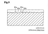
Fig. 9 is an enlarged longitudinal sectional view of an essential part ofFig. 9 ; -
Fig. 10 is a perspective view of the sleeve showing only one of the rugged lines formed on the outer surface schematically and in magnification; -
Fig. 11 is an enlarged plan view of the rugged line ofFig. 10 ; -
Fig. 12 is a longitudinal sectional view taken along the line XII-XII ofFig. 11 ; -
Fig. 13 is a cross-sectional view taken along the line XIII-XIII ofFig. 12 ; -
Fig. 14 is a cross-sectional view taken along the line XIV-XIV ofFig. 12 ; -
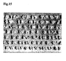
Fig. 15 is a figure of an essential part of the sleeve shown inFig. 6 ; and -
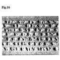
Fig. 16 is a figure of an essential part of the sleeve shown inFig. 7 . - Hereinafter, embodiments of the present invention will be described with reference to
Figs. 1 to 16 . - As shown in
Fig. 1a , moltenlight alloy 1 containing Al-73 %, Si-17 %, Fe-5 %, Cu-3.5 %, Mg-1 % and Mn-0.5 % (weight %) is charged in a crucible 3 from apot 2. The molten light alloy drops through an opening provided at a bottom of the crucible. At that time, the molten light alloy becomes fine particles and is rapidly cooled by air or inert gas blown at a high speed from nozzles 4 surrounding the opening, and matrix sub-/per-eutectic aluminumsilicon alloy powder 5 is formed (atomizing process). - The matrix sub-/per-eutectic aluminum
silicon alloy powder 5 is charged into a mixing vessel 6 together with alumina powder giving abrasion resistance and graphite powder giving self-lubricating nature (Fig. 1b ). Then, the mixing vessel 6 is closed tight and rotated about ahorizontal axis 7 so that the powder is mixed uniformly and bulletraw material powder 8 is obtained. - As shown in
Fig. 1c , the bulletraw material powder 8 is charged into acylindrical rubber bag 10 in which acore 9 having a diameter corresponding to a diameter of a cylinder bore of an internal combustion engine is disposed. Thecylindrical rubber bag 10 is housed in acylindrical pressure vessel 12 having upper andlower lids 11. A liquid such as water is charged in thecylindrical pressure vessel 12 and given pressure of 1.6 GPa to preparatively form a hollow cylindrical bullet 13 (Fig. 1d ) having a uniform density distribution and a density ratio of about 70 % (cold hydrostatic pressure forming process). - The hollow
cylindrical bullet 13 is put in a heating furnace (not shown) and preheated and degassed under nitrogen atmospheric gas (Fig. 1e ). Then, the hollowcylindrical bullet 13 is charged in a container 15 of ahot extrusion apparatus 14 shown inFig. 1f . In the container 15, amandrel 16 is inserted in a central hole of the hollowcylindrical bullet 13. Themandrel 16 is fixed so that a front end of themandrel 16 is positioned on a extrusion side of a die 17 fixed to the container 15. A front end of amain ram 18 is touched to a back side of the hollowcylindrical bullet 13 so that the hollowcylindrical bullet 13 is extruded when themain ram 18 moves in a extruding direction X. The extruded hollowcylindrical bullet 13 is cut by mechanical work to obtainsleeves 19 of predetermined length (Fig. 1g ). - As shown in
Figs. 2 and 3 , thedie 17 has acircular opening 17a having an inner diameter of 94.3 mm, and on the peripheral surface of theopening 17a are formedgrooves 17b of width W and depth H arranged circumferentially uniformly. - As shown in
Fig. 5 , in anembodiment 1 includingsamples 1 to 5, all samples have the same groove width W of 0.38 mm and the same groove span (center angle) of 1.5° but have different respective groove heights of 1 mm, 0.7 mm, 0.5 mm, 0.3 mm and 0.2 mm. In thesamples sleeve 19 and irregularrugged lines 20 are formed as shown inFigs. 6 to 9 ,10 to 14 and15 to 16 . - If peripheral length of the
groove 17b is long, the hollowcylindrical bullet 13 is subjected to a large resistance owing to contact with thegrooves 17b of the die 17 when thebullet 13 passes through thegrooves 17b, so that the above-mentioned tears are produced. - The "tear producing rate" in
Fig. 5 means a ratio of a number of the projecting lines on which irregular rugged lines are formed by the tear to the total number of the projecting lines on thesleeve 19. In thesamples - In the
rugged line 20 shown inFigs. 6 to 9 , wide andhigh portions 20a (irregularely shapedportions 20a) and narrow andlow portions 20b are arranged irregularly in direction of extrusion, and in the wide andhigh portion 20a, a tip end portion is wider than a base portion near a surface of agroove 21 of the sleeve 19 (the base portion is constricted as shown inFigs. 10 and 11 ). Further, the surface of the wide andhigh portions 20a is formed in an irregular rugged surface. Therefore, thesleeve 19 and a cylinder block cast-wrapping thesleeve 19 are mechanically combined strongly. - Since at least a part of the tip end of the wide and
high portion 20a of therugged line 20 is formed in a sharp shape, heat of the cast-wrapping molten metal for the cylinder block is added to the sharp tip end of theportion 20a concentrically to melt an oxidized film on theportion 20a, so that a sure metallurgical combination can be obtained. - Each of the wide and
high portions 20a of therugged line 20 has a side near an extrusion starting end that is wider and higher and another side near an extrusion completing end that is narrower and lower, and an end surface of the wide andhigh portion 20a at the extrusion starting end is inclined in the extrusion direction from the base portion toward the tip end portion (Fig. 9 andFig. 12 ). Therefore, when thesleeve 19 cast-wrapped by the cylinder block is forced in the extrusion direction, a large resistance is exhibited. - In the
samples sleeve 19 has the irregularrugged lines 20 on the outer surface, heat of molten metal for the cylinder block cast-wrapping thesleeve 19 is rapidly transferred to an irregular rugged surface of therugged line 20, so that the rugged surface is melted at a sufficiently high temperature for metallurgical combination. Moreover, since the tip end of the wide andhigh portion 20a of therugged line 20 is bent like a hook and the bottom part of theportion 20a is made wide (seeFig. 12 ), thesleeve 19 and the cylinder block is strongly combined mechanically, so that thesleeve 19, which comes into sliding contact with a piston and is subjected to various forces, can be held by the cylinder block stably and firmly. - Even if a thermal stress is generated so as to separate the
sleeve 19 and the cylinder block owing to a difference of thermal expansion between thesleeve 19 and the cylinder block, thesleeve 19 and the cylinder block is kept in a strongly combined state and there is no fear that a gap is generated between them. - Since the
sleeve 19 and the cylinder block are combined tight without a gap, heat of thesleeve 19, which is contacted with a combustion chamber and heated, escapes through the cylinder block having a high heat transfer coefficient, and thesleeve 19 is kept at a suitable temperature. Therefore, knocking performance is improved, load of the cooling system is lowered, and space between neighboringsleeves 19 can be shortened to miniaturize the internal combustion engine. - In case that the sub-/per-eutectic aluminum
silicon alloy sleeve 19 having projections of undercut shapes formed on the outer peripheral surface during extrusion of thesleeve 19 is cast-wrapped by a cylinder block (not shown) produced by high pressure die casting, following features can be obtained. - When the outer peripheral surface of the
sleeve 19 is cast-wrapped by the cylinder block, molten metal for the cylinder block surrounds entirely the projectingportion 20a of undercut shape by injection pressure of the die casting. At that time, a strong oxidized film on the tip end of the projectingportion 20a having small heat-mass is locally melted by thermal energy of the molten metal. Thus, both a mechanical combination and a metallurgical combination are carried out and high adhesion combining force can be obtained. - Since different kinds of combinations can be carried out simultaneously in the injection process of the cylinder block, gaps produced between the cylinder block and the outer peripheral surface of the sleeve are few. Therefore, the piston is cooled effectively, knocking performance is improved, and heat generated in the combustion chamber can be led to cooling system effectively. Since the sleeve is fixed to the cylinder block firmly, oil-up is reduced and exhaust emission (hydrocarbon) can be reduced.
- If the cylinder block is subjected to age heat treatment in consideration of thermal history, gaps between the sleeve and the cylinder block are very few and therefore combination of the sleeve and the cylinder block is strong, so that deformation of an inner peripheral surface of the bore in course of operation is reduced, and as the result, oil consumption and blow-by performance are improved.
- In the
samples 3, 4, 5 of the table shown inFig. 5 , H/W are less than 1.5 and as the result, the tear producing rates are low. - In an
embodiment 2 in the table ofFig. 5 , the same hollowcylindrical bullet 13 as the bullet in theembodiment 1 is used, and H and W of the samples 6-10 are selected so that H/W of all of the samples are 2.7 (more than 1.5). In thesamples groove 17b of the die 17 is smaller than 1.3 mm, the tear producing rate is more than 70 %. Accordingly, the samples 6. 7. 8 and 9 can be put to practical use. - But, in the
sample 10, since the width of thegroove 17b of the die 17 is 1.5 mm more than 1.3 mm, the tear is not produced. Accordingly thesleeve 19 extruded from thedie 17 has the same cross-section as that of thedie 17 and thesleeve 19 can not be put to practical use. - In an embodiment 3 in the table of
Fig. 5 , powder having a composition (Al-58.5%, Si-25%, Cu-4.5%, Mg-1.5%, Al2O3-10% and Gr (graphite particle)-0.5%) other than that in theembodiment 1 is shaped at a pressure of 1.6 GPa by cold hydrostatic pressure press to obtain the hollowcylindrical bullet 13. The hollowcylindrical bullet 13 is hot extruded at a state heated to 450 QC. The above powder is made in such a manner that after matrix sub-/per-eutectic aluminum silicon alloy powder is shaped by atomizing process similarly to theembodiment 1, Al2O3 and Gr are added. - In the
samples groove 17b of the die 17 is less than 1.3 and peripheral length ratio L/d · π is more than 1.5, tear producing rate is 92 % or 87 % and goodrugged line 20 is formed. - However, in the
samples - In an embodiment 4 in the table of
Fig. 5 , the same hollowcylindrical bullet 13 as that in the embodiment 3 is used. In each of thesamples 15, 16, thegroove 17b of the die 17 is formed in T-shape as shown inFig. 4 , inner peripheral length of the die 17 is necessarily long, correspondingly the peripheral length ratio L/d · π is remarkably larger than 1. 5 and therefore tear producing rate is 100 %. - In the
samples samples 15, 16, therefore tear producing rate is high but does not reach 100 %. - In the above-mentioned embodiments, the metal member to be cast-wrapped is a sinter-extruded article (sleeve 19), but it may be an ordinary extruded article, a forged article or a cast article.
- The present invention can be applied to a metal member to be cast-wrapped by a metal cast article such as a sleeve of an internal combustion engine to be cast-wrapped by a cylinder block or the like.
Claims (11)
- A metal member which has been cast-wrapped by a metal cast article, wherein a surface of said metal member (19) cast-wrapped by said metal cast article is an irregular surface (20, 21) with projections (20a) projecting therefrom, and a maximum width of said projections (20a) at a tip end portion is wider than a maximum width of the projections (20a) at a base portion,
characterized in that said metal member (19) is an extruded member (19) having grooves (21) extending in the extruding direction and said projections (20a) are formed between said grooves (21) as irregularly shaped projections (20a) separated from each other in the extrusion direction, wherein said projections (20a) are lined up in rugged lines (20) extending in the extrusion direction, wherein adjacent rugged lines (20) are separated from each other by the grooves (21), and the grooves (21) have no such projections (20a), wherein said projections (20a) are metallurgically combined with the cast-wrapping material. - A metal member as claimed in claim 1, wherein at least a part of said tip end portion of each of said projections (20a) is formed in a tapering sharp shape.
- A metal member as claimed in claim 1, wherein said irregularly shaped projections (20a) near an extrusion starting end are wide and high, and said irregularly shaped projections near an extrusion completing end are narrow and low.
- A metal member as claimed in claim 1 or 2, wherein said metal member (19) to be cast-wrapped is a hollow cylindrical body (19).
- A metal member as claimed in claim 1, wherein said metal member (19) is cylindrical, wherein said metal member (19) has an outer surface formed with said projections (20a), said projections (20a) are arranged in axially extending rows and separated circumferentially at regular intervals through said grooves (21), and
wherein said projections (20a) are separated from each other in the axial direction and tip end portions of said projections (20a) are bent laterally. - A metal member as claimed in claim 1, wherein said metal member (19) is cylindrical, wherein said metal member (19) has an outer surface formed with said projections (20a), said projections (20a) are arranged in axially extending rows and separated circumferentially at regular intervals through said grooves (21), and
wherein said projections (20a) are separated from each other in the axial direction and tip end portions of said projections (20a) are bent in axial direction. - A metal member as claimed in claim 5 or 6, wherein said projections (20a) are aligned axially at irregular intervals and are not aligned circumferentially.
- A method for manufacturing a cylindrical metal member (19) having an irregular outer surface (20, 21) with projections (20a) and cast-wrapping said cylindrical metal member (19) by a metal cast article; comprising:preparing a die (17) having an inner peripheral surface formed with longitudinal grooves (17b) of depth H and width W, relation between a maximum depth HMAX and a minimum width WMIN of the groove being set as HMAX / WMIN 1.5;inserting a cylindrical metal material in said die (17);hot-extruding said cylindrical metal material to obtain the cylindrical metal member (19) having an outer surface with projections (20a), wherein the inner peripheral surface of the die (17) forms grooves (21) provided in the cylindrical metal member (19) and extending in the extruding direction, and forms said projections (20a) as irregularly shaped projections (20a) separated from each other in the extrusion direction between said grooves (21) of said cylindrical metal member (19) owing to a large resistance to contact with the grooves (17b) of the die (17), such that a maximum width of said projections (20a) at a tip end portion is wider than a maximum width of the projections (20a) at a base portion, and said projections (20a) are lined up in rugged lines (20) extending in the extrusion direction, wherein adjacent rugged lines (20) are separated from each other by the grooves (21), and the grooves (21) have no such projections (20a); andcast-wrapping said cylindircal metal member (19) by said metal cast article while metallurgically combining said projections (20a) with the material of said cast wrapping article.
- A method as claimed in claim 8, wherein said minimum width WMIN of said groove (17b) is set as WMIN 1.3 mm.
- A method as claimed in claim 8 or 9, wherein the relation between a minimum inner diameter d and a total inner peripheral length L of a cross-section of said die (17) is set as L / d · π 1.5.
- A method as claimed in claim 8 or 9, wherein said metal member to be cast-wrapped is a hollow cylindrical body (19).
Applications Claiming Priority (3)
| Application Number | Priority Date | Filing Date | Title |
|---|---|---|---|
| JP2000211747A JP3976991B2 (en) | 2000-07-12 | 2000-07-12 | Metal casting wrap |
| JP2000211747 | 2000-07-12 | ||
| PCT/JP2001/005141 WO2002004150A1 (en) | 2000-07-12 | 2001-06-15 | Metallic inserted member, method of manufacturing metallic inserted member, and metallic cast part |
Publications (3)
| Publication Number | Publication Date |
|---|---|
| EP1300206A1 EP1300206A1 (en) | 2003-04-09 |
| EP1300206A4 EP1300206A4 (en) | 2004-04-14 |
| EP1300206B1 true EP1300206B1 (en) | 2008-04-02 |
Family
ID=18707803
Family Applications (1)
| Application Number | Title | Priority Date | Filing Date |
|---|---|---|---|
| EP01941072A Expired - Lifetime EP1300206B1 (en) | 2000-07-12 | 2001-06-15 | Metallic inserted member, method of manufacturing metallic inserted member, and metallic cast part |
Country Status (10)
| Country | Link |
|---|---|
| US (1) | US7014924B2 (en) |
| EP (1) | EP1300206B1 (en) |
| JP (1) | JP3976991B2 (en) |
| CN (1) | CN1203944C (en) |
| BR (1) | BR0106965B1 (en) |
| CA (1) | CA2383964C (en) |
| DE (1) | DE60133466T2 (en) |
| ES (1) | ES2304387T3 (en) |
| MY (1) | MY141109A (en) |
| WO (1) | WO2002004150A1 (en) |
Families Citing this family (15)
| Publication number | Priority date | Publication date | Assignee | Title |
|---|---|---|---|---|
| JP3300331B2 (en) * | 2000-09-01 | 2002-07-08 | 本田技研工業株式会社 | Manufacturing method of cylindrical metal cast member |
| JP4033147B2 (en) * | 2004-02-24 | 2008-01-16 | 株式会社豊田自動織機 | Casting method and casting for castings |
| WO2010095590A1 (en) * | 2009-02-18 | 2010-08-26 | 株式会社Ihi | Electrode manufacturing method and electric discharge surface treatment used therein |
| CN102401129B (en) * | 2010-09-15 | 2015-06-17 | 上海工程机械厂有限公司 | Cast-in piston body and casting method thereof |
| JP5591136B2 (en) * | 2011-01-28 | 2014-09-17 | 大同特殊鋼株式会社 | Manufacturing method of deformed metal ring |
| US20120273539A1 (en) * | 2011-04-28 | 2012-11-01 | GM Global Technology Operations LLC | Support structure and method of manufacturing the same |
| US10094325B2 (en) * | 2014-01-28 | 2018-10-09 | ZYNP International Corp. | Cylinder liner |
| CN105081694A (en) * | 2015-08-14 | 2015-11-25 | 丁海迅 | Ratchet ring manufacturing technologies |
| US10132267B2 (en) | 2015-12-17 | 2018-11-20 | Ford Global Technologies, Llc | Coated bore aluminum cylinder liner for aluminum cast blocks |
| US10066577B2 (en) | 2016-02-29 | 2018-09-04 | Ford Global Technologies, Llc | Extruded cylinder liner |
| JP6984289B2 (en) * | 2017-10-03 | 2021-12-17 | スズキ株式会社 | Casting and packaging members and their manufacturing methods |
| JP6979171B2 (en) * | 2017-11-16 | 2021-12-08 | スズキ株式会社 | Casting and packaging members and their manufacturing methods |
| JP7039953B2 (en) * | 2017-11-21 | 2022-03-23 | スズキ株式会社 | Casting and packaging members and their manufacturing methods |
| CN111168037B (en) * | 2020-01-16 | 2021-03-16 | 青岛力晨新材料科技有限公司 | Stainless steel/carbon steel composite pipe and manufacturing process thereof |
| AT526113B1 (en) * | 2022-04-12 | 2025-03-15 | Manfred Serbinek | Cast component with a surface structure |
Family Cites Families (13)
| Publication number | Priority date | Publication date | Assignee | Title |
|---|---|---|---|---|
| JPS4944857B1 (en) * | 1970-12-28 | 1974-11-30 | ||
| JPS4944857A (en) | 1972-09-06 | 1974-04-27 | ||
| JPS52138017A (en) * | 1976-05-14 | 1977-11-17 | Taiho Kogyo Co Ltd | Compound material of aluminium group casting base and ferrous group annexation and its production method |
| JPS5399040A (en) * | 1977-02-10 | 1978-08-30 | Yanmar Diesel Engine Co | Preparation of cylindrical body |
| SE431723B (en) * | 1980-06-23 | 1984-02-27 | Sandvik Ab | WELDABLE Wear Part with High Durability |
| USRE34442E (en) * | 1987-07-20 | 1993-11-16 | Norsk Hydro A.S | Method for producing an aluminum alloy |
| JPH01317679A (en) * | 1987-12-14 | 1989-12-22 | Nippon Piston Ring Co Ltd | Hollow cylindrical body for embedding by casting and production thereof |
| JP3161301B2 (en) * | 1995-02-21 | 2001-04-25 | トヨタ自動車株式会社 | Cylinder liner for cast-in |
| DE19634504A1 (en) * | 1996-08-27 | 1997-12-04 | Daimler Benz Ag | Manufacture of blank of a light-metal component to be incorporated into a light-metal casting |
| DE19639052C2 (en) * | 1996-09-24 | 1998-07-09 | Daimler Benz Ag | Thin-walled die-cast part made of light metal as a structural component for car bodies |
| EP0892080B1 (en) * | 1997-07-16 | 2002-10-09 | The Furukawa Electric Co., Ltd. | Aluminum alloy tube and heat exchanger, and method of metal spraying a filler alloy |
| DE19753017A1 (en) * | 1997-12-01 | 1999-06-02 | Ks Aluminium Technologie Ag | Cylinder liner |
| US20020019321A1 (en) * | 1998-02-17 | 2002-02-14 | Robert W. Balliett | Metalworking lubrication |
-
2000
- 2000-07-12 JP JP2000211747A patent/JP3976991B2/en not_active Expired - Fee Related
-
2001
- 2001-06-15 ES ES01941072T patent/ES2304387T3/en not_active Expired - Lifetime
- 2001-06-15 EP EP01941072A patent/EP1300206B1/en not_active Expired - Lifetime
- 2001-06-15 BR BRPI0106965-9A patent/BR0106965B1/en not_active IP Right Cessation
- 2001-06-15 US US10/069,976 patent/US7014924B2/en not_active Expired - Fee Related
- 2001-06-15 DE DE60133466T patent/DE60133466T2/en not_active Expired - Fee Related
- 2001-06-15 WO PCT/JP2001/005141 patent/WO2002004150A1/en not_active Ceased
- 2001-06-15 CA CA002383964A patent/CA2383964C/en not_active Expired - Fee Related
- 2001-06-15 CN CN01801983.8A patent/CN1203944C/en not_active Expired - Fee Related
- 2001-07-10 MY MYPI20013268A patent/MY141109A/en unknown
Also Published As
| Publication number | Publication date |
|---|---|
| JP3976991B2 (en) | 2007-09-19 |
| EP1300206A4 (en) | 2004-04-14 |
| BR0106965B1 (en) | 2009-01-13 |
| CN1203944C (en) | 2005-06-01 |
| DE60133466T2 (en) | 2009-04-09 |
| ES2304387T3 (en) | 2008-10-16 |
| US20020134128A1 (en) | 2002-09-26 |
| MY141109A (en) | 2010-03-15 |
| EP1300206A1 (en) | 2003-04-09 |
| CN1386078A (en) | 2002-12-18 |
| JP2002028768A (en) | 2002-01-29 |
| CA2383964A1 (en) | 2002-01-17 |
| US7014924B2 (en) | 2006-03-21 |
| BR0106965A (en) | 2002-06-04 |
| CA2383964C (en) | 2007-09-11 |
| WO2002004150A1 (en) | 2002-01-17 |
| DE60133466D1 (en) | 2008-05-15 |
Similar Documents
| Publication | Publication Date | Title |
|---|---|---|
| CA2383964C (en) | A metal member to be cast-wrapped and a method for manufacturing a metalmember to be cast-wrapped | |
| US7472674B2 (en) | Method of manufacture of a piston for an internal combustion engine, and piston thus obtained | |
| US5878804A (en) | Multiproperty metal forming process | |
| JP2011012338A (en) | Aluminum alloy for vehicle cylinder liner and method of manufacturing vehicle cylinder liner using the same | |
| US7073492B2 (en) | Cylinder crankcase, procedure for manufacturing the cylinder bushings for the cylinder crankcase, and procedure for manufacturing the cylinder crankcase with these cylinder bushings | |
| EP3075875A1 (en) | Aluminium alloy for aerosol cans manufactured by the impact extrusion and the process for preparation thereof | |
| KR100269898B1 (en) | Process for manufacturing thin pipes | |
| CA2164486C (en) | Metallic ingot for plastic working and method for producing the same | |
| NZ524223A (en) | Aluminium pressure casting | |
| JPS60234958A (en) | Manufacture of continuous casting mold with abrasion-resistant layer and mold thereby | |
| US6802121B2 (en) | Method for producing a cylinder block for an internal combustion engine | |
| EP0971117B1 (en) | Method for manufacturing piston by forging, forging die and piston | |
| US6502624B1 (en) | Multiproperty metal forming process | |
| US5507258A (en) | Pistons for internal combustion engines | |
| AU2855200A (en) | Activated feedstock | |
| US6003585A (en) | Multiproperty metal forming process | |
| JP2000109944A (en) | Abrasion-resistant, high-strength aluminum alloy compact, method for producing the same, and cylinder liner comprising the compact | |
| EP0870919B1 (en) | Piston for an internal combustion engine and a method for producing same | |
| JP4509335B2 (en) | Method for producing cylindrical metal cast-in member | |
| US5230382A (en) | Process of producing individual eccentric cams from cast metal | |
| EP0257425A2 (en) | Casting | |
| JP2000179399A (en) | Forged piston for 4 cycle engine | |
| US20040194307A1 (en) | Manufacturing pistons | |
| US6889746B2 (en) | Material for plastic working and production method thereof | |
| JP4104220B2 (en) | FORGING DIE FOR FORGING PISTON FOR INTERNAL COMBUSTION ENGINE AND METHOD FOR PRODUCING PISTON |
Legal Events
| Date | Code | Title | Description |
|---|---|---|---|
| PUAI | Public reference made under article 153(3) epc to a published international application that has entered the european phase |
Free format text: ORIGINAL CODE: 0009012 |
|
| 17P | Request for examination filed |
Effective date: 20020205 |
|
| AK | Designated contracting states |
Kind code of ref document: A1 Designated state(s): AT BE CH CY DE DK ES FI FR GB GR IE IT LI LU MC NL PT SE TR |
|
| AX | Request for extension of the european patent |
Extension state: AL LT LV MK RO SI |
|
| RAP1 | Party data changed (applicant data changed or rights of an application transferred) |
Owner name: HONDA GIKEN KOGYO KABUSHIKI KAISHA |
|
| A4 | Supplementary search report drawn up and despatched |
Effective date: 20040301 |
|
| RIC1 | Information provided on ipc code assigned before grant |
Ipc: 7B 22D 19/00 A |
|
| RBV | Designated contracting states (corrected) |
Designated state(s): DE ES FR GB |
|
| 17Q | First examination report despatched |
Effective date: 20051004 |
|
| GRAP | Despatch of communication of intention to grant a patent |
Free format text: ORIGINAL CODE: EPIDOSNIGR1 |
|
| GRAS | Grant fee paid |
Free format text: ORIGINAL CODE: EPIDOSNIGR3 |
|
| GRAA | (expected) grant |
Free format text: ORIGINAL CODE: 0009210 |
|
| RIN1 | Information on inventor provided before grant (corrected) |
Inventor name: YAMADA, KOUJI Inventor name: SHIGA, RYUJI Inventor name: MITSUUCHI, KAORU Inventor name: ARIMURA, MITSUNORI Inventor name: KOYAMA, YOSHIAKI Inventor name: SHIBASAKI, TOSHIYUKI Inventor name: ITOU, YOSHIAKI |
|
| AK | Designated contracting states |
Kind code of ref document: B1 Designated state(s): DE ES FR GB |
|
| REG | Reference to a national code |
Ref country code: GB Ref legal event code: FG4D |
|
| REF | Corresponds to: |
Ref document number: 60133466 Country of ref document: DE Date of ref document: 20080515 Kind code of ref document: P |
|
| REG | Reference to a national code |
Ref country code: ES Ref legal event code: FG2A Ref document number: 2304387 Country of ref document: ES Kind code of ref document: T3 |
|
| ET | Fr: translation filed | ||
| PLBE | No opposition filed within time limit |
Free format text: ORIGINAL CODE: 0009261 |
|
| STAA | Information on the status of an ep patent application or granted ep patent |
Free format text: STATUS: NO OPPOSITION FILED WITHIN TIME LIMIT |
|
| 26N | No opposition filed |
Effective date: 20090106 |
|
| PGFP | Annual fee paid to national office [announced via postgrant information from national office to epo] |
Ref country code: ES Payment date: 20090709 Year of fee payment: 9 |
|
| PGFP | Annual fee paid to national office [announced via postgrant information from national office to epo] |
Ref country code: DE Payment date: 20090615 Year of fee payment: 9 Ref country code: GB Payment date: 20090610 Year of fee payment: 9 |
|
| GBPC | Gb: european patent ceased through non-payment of renewal fee |
Effective date: 20100615 |
|
| REG | Reference to a national code |
Ref country code: FR Ref legal event code: ST Effective date: 20110228 |
|
| PG25 | Lapsed in a contracting state [announced via postgrant information from national office to epo] |
Ref country code: DE Free format text: LAPSE BECAUSE OF NON-PAYMENT OF DUE FEES Effective date: 20110101 |
|
| PG25 | Lapsed in a contracting state [announced via postgrant information from national office to epo] |
Ref country code: FR Free format text: LAPSE BECAUSE OF NON-PAYMENT OF DUE FEES Effective date: 20100630 |
|
| REG | Reference to a national code |
Ref country code: ES Ref legal event code: FD2A Effective date: 20110714 |
|
| PG25 | Lapsed in a contracting state [announced via postgrant information from national office to epo] |
Ref country code: GB Free format text: LAPSE BECAUSE OF NON-PAYMENT OF DUE FEES Effective date: 20100615 Ref country code: ES Free format text: LAPSE BECAUSE OF NON-PAYMENT OF DUE FEES Effective date: 20110704 |
|
| PG25 | Lapsed in a contracting state [announced via postgrant information from national office to epo] |
Ref country code: ES Free format text: LAPSE BECAUSE OF NON-PAYMENT OF DUE FEES Effective date: 20100616 |
|
| PGFP | Annual fee paid to national office [announced via postgrant information from national office to epo] |
Ref country code: FR Payment date: 20090611 Year of fee payment: 9 |