EP1300177A1 - Method for collecting and eliminating flying dust - Google Patents
Method for collecting and eliminating flying dust Download PDFInfo
- Publication number
- EP1300177A1 EP1300177A1 EP02002683A EP02002683A EP1300177A1 EP 1300177 A1 EP1300177 A1 EP 1300177A1 EP 02002683 A EP02002683 A EP 02002683A EP 02002683 A EP02002683 A EP 02002683A EP 1300177 A1 EP1300177 A1 EP 1300177A1
- Authority
- EP
- European Patent Office
- Prior art keywords
- blower
- jet
- nozzles
- air
- water
- Prior art date
- Legal status (The legal status is an assumption and is not a legal conclusion. Google has not performed a legal analysis and makes no representation as to the accuracy of the status listed.)
- Granted
Links
- 239000000428 dust Substances 0.000 title claims abstract description 11
- 238000000034 method Methods 0.000 title claims abstract description 11
- XLYOFNOQVPJJNP-UHFFFAOYSA-N water Substances O XLYOFNOQVPJJNP-UHFFFAOYSA-N 0.000 claims abstract description 12
- 238000002347 injection Methods 0.000 claims abstract 2
- 239000007924 injection Substances 0.000 claims abstract 2
- 238000005507 spraying Methods 0.000 claims abstract 2
- 239000004094 surface-active agent Substances 0.000 claims description 7
- 239000002245 particle Substances 0.000 claims description 3
- 239000007864 aqueous solution Substances 0.000 claims 1
- 230000015572 biosynthetic process Effects 0.000 claims 1
- 238000005054 agglomeration Methods 0.000 description 1
- 230000002776 aggregation Effects 0.000 description 1
- 238000001816 cooling Methods 0.000 description 1
- 239000012530 fluid Substances 0.000 description 1
- 239000000446 fuel Substances 0.000 description 1
- 238000012423 maintenance Methods 0.000 description 1
- 230000002093 peripheral effect Effects 0.000 description 1
- 239000002244 precipitate Substances 0.000 description 1
- 239000003380 propellant Substances 0.000 description 1
- 239000003381 stabilizer Substances 0.000 description 1
Images

Classifications
-
- A—HUMAN NECESSITIES
- A62—LIFE-SAVING; FIRE-FIGHTING
- A62C—FIRE-FIGHTING
- A62C3/00—Fire prevention, containment or extinguishing specially adapted for particular objects or places
- A62C3/02—Fire prevention, containment or extinguishing specially adapted for particular objects or places for area conflagrations, e.g. forest fires, subterranean fires
- A62C3/0207—Fire prevention, containment or extinguishing specially adapted for particular objects or places for area conflagrations, e.g. forest fires, subterranean fires by blowing air or gas currents with or without dispersion of fire extinguishing agents; Apparatus therefor, e.g. fans
-
- A—HUMAN NECESSITIES
- A62—LIFE-SAVING; FIRE-FIGHTING
- A62C—FIRE-FIGHTING
- A62C3/00—Fire prevention, containment or extinguishing specially adapted for particular objects or places
- A62C3/04—Fire prevention, containment or extinguishing specially adapted for particular objects or places for dust or loosely-baled or loosely-piled materials, e.g. in silos, in chimneys
Definitions
- the present invention relates to a method for collecting and eliminating flying dust and for fire extinguishing use, and the apparatus for implementing it.
- An object of the invention is to solve the problem of collecting and eliminating flying dust present in open zones without the need to use filters or means which in their turn can give rise to pollution.
- Another object of the invention is to effectively solve the problem of extinguishing fires.
- the method of the invention consists essentially of collecting and eliminating the flying dust by striking the open area containing this flying dust with a jet of atomized water, the water being either alone or mixed with an active ecological surfactant (known per se).
- the jet can be propelled to a distance of 250 metres or more.
- the apparatus of the invention shown here by way of example in the drawings, consists of an easily transportable module (of relatively small dimensions when assembled, for example 2.4 m wide by 7 m long and by about 2.8 m high) which is easy to locate on any suitable surface.
- the module in question comprises a base 1 for example of structural metalwork, provided where necessary with adjustable stabilizers 2 and defining a platform.
- the engine 3 operates a series of preferably coaxial oil pumps (Figure 5), the function of which is described hereinafter.
- a tube-encased blower 6 operated by a rotary hydraulic motor 7 connected to a pump of the pump series 5.
- the air jet produced by the blower strikes particles of water (with or without surfactant) fed through one or more rings of nozzles 8. These nozzles are fed by a pump operated by a hydraulic motor 10 operationally connected to one of the pumps of the pump series 5.
- the pump 9 and the hydraulic motor 10 are both mounted on the platform. The pump 9 draws the water or the water-surfactant solution from a tank incorporated into the base 1.
- a tank 18 for the oil which is withdrawn by the pumps of the series 5 and returned to the tank from the hydraulic motors connected to these pumps.
- the blower 6 can be swivelled (i.e. rotated about a vertical axis), and can also be inclined about a horizontal axis.
- the blower 6 is mounted rotatable on a horizontal joint 12 supported by a rotatable platform 13 supported by a thrust bearing (not visible) provided on the base.
- the rotatable platform 13 presents a peripheral toothing (not visible) with which there engages a gearwheel (also not visible) operated by a rotary hydraulic motor 14 mounted in the base 1.
- hydraulic actuators 15 are provided connected for example by their rod to the blower and by their cylinder to the rotatable platform 13. Both the rotary hydraulic motor 14 and the actuators 15 are fed by pumps of the pump series 5 (via valve members to control the described movements).
- a conventional radiator 16 for the diesel engine 3 and a heat exchanger 17 for cooling the oil are also present on the platform.
- the module operation can be automated electronically and be also arranged for remote radio control.
- the module operation comprises control of the approach and adjustment of the engine 3, control of the raising and swivelling of the blower, control of the speed of the blower 6, and control of the delivery pressure of the pump 9.
- the method for collecting and eliminating flying dust is implemented in a apparatus which produces and propels a fluid jet composed of air and water with or without surfactant, for distribution within the surrounding environment with uniformity of distribution throughout the zone of the jet from the vicinity of the jet to 250 metres therefrom, to depolverize a plan area of about 65,000 m 2 and enable the particles of flying dust to undergo agglomeration and increase in weight, so that they precipitate to the ground within the area of influence and avoid their inhalation by surrounding persons and pollution of adjacent areas.
- the apparatus can also be used for extinguishing fires, and has demonstrated absolute effectiveness during tests carried out in industrial and woodland applications.
Landscapes
- Health & Medical Sciences (AREA)
- Public Health (AREA)
- Business, Economics & Management (AREA)
- Emergency Management (AREA)
- Chemical & Material Sciences (AREA)
- Dispersion Chemistry (AREA)
- Life Sciences & Earth Sciences (AREA)
- Biodiversity & Conservation Biology (AREA)
- Ecology (AREA)
- Forests & Forestry (AREA)
- Developing Agents For Electrophotography (AREA)
- Structures Of Non-Positive Displacement Pumps (AREA)
- Catching Or Destruction (AREA)
- Fire-Extinguishing Compositions (AREA)
- Filtering Of Dispersed Particles In Gases (AREA)
- Waste-Gas Treatment And Other Accessory Devices For Furnaces (AREA)
- Solid-Sorbent Or Filter-Aiding Compositions (AREA)
- Treatment Of Liquids With Adsorbents In General (AREA)
- Disintegrating Or Milling (AREA)
- Separation Of Particles Using Liquids (AREA)
Abstract
Description
- The present invention relates to a method for collecting and eliminating flying dust and for fire extinguishing use, and the apparatus for implementing it.
- As is well known, flying dust represents a serious danger both for people and for the environment.
- Various attempts have been made to solve the problem, for example by collecting the dust by suction and passing it through suitable filters (requiring constant maintenance). Such a solution can achieve a certain result if applied to closed or substantially closed environments, but is certainly not feasible in open zones such as roads, yard areas and the like.
- An object of the invention is to solve the problem of collecting and eliminating flying dust present in open zones without the need to use filters or means which in their turn can give rise to pollution.
- Another object of the invention is to effectively solve the problem of extinguishing fires.
- These and further objects which will be apparent from the ensuing detailed description are attained by a method and apparatus in accordance with the teachings of the accompanying claims.
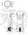
- The invention will be more apparent from the ensuing detailed description of a preferred embodiment thereof, provided by way of non-limiting example and illustrated in the accompanying drawing, in which:
- Figure 1 is a schematic side elevation of an apparatus according to the invention;
- Figure 2 is a front schematic view of the apparatus in the direction of the arrow A;
- Figure 3 is a schematic plan view of the apparatus;
- Figures 4 and 5 are a more schematic side elevation and plan view of the apparatus with some parts omitted, said two figures illustrating the facility for orientating the so-called "propellant" part of the apparatus.
-
- The method of the invention consists essentially of collecting and eliminating the flying dust by striking the open area containing this flying dust with a jet of atomized water, the water being either alone or mixed with an active ecological surfactant (known per se).
- By suitably dimensioning the apparatus to be described, the jet can be propelled to a distance of 250 metres or more.
- The apparatus of the invention, shown here by way of example in the drawings, consists of an easily transportable module (of relatively small dimensions when assembled, for example 2.4 m wide by 7 m long and by about 2.8 m high) which is easy to locate on any suitable surface.
- The module in question comprises a base 1 for example of structural metalwork, provided where necessary with
adjustable stabilizers 2 and defining a platform. - On this platform there is mounted a conventional electric motor or preferably a
diesel engine 3 drawing the necessary fuel from a tank 4 (Figure 3) located on the platform or incorporated into the base 1. Theengine 3 operates a series of preferably coaxial oil pumps (Figure 5), the function of which is described hereinafter. - On the platform the is also mounted a tube-encased
blower 6 operated by a rotary hydraulic motor 7 connected to a pump of thepump series 5. - The air jet produced by the blower strikes particles of water (with or without surfactant) fed through one or more rings of
nozzles 8. These nozzles are fed by a pump operated by ahydraulic motor 10 operationally connected to one of the pumps of thepump series 5. Thepump 9 and thehydraulic motor 10 are both mounted on the platform. Thepump 9 draws the water or the water-surfactant solution from a tank incorporated into the base 1. - On the platform there is also mounted a
tank 18 for the oil, which is withdrawn by the pumps of theseries 5 and returned to the tank from the hydraulic motors connected to these pumps. - As can be seen from Figures 1, 2, 4 and 5 in particular, the
blower 6 can be swivelled (i.e. rotated about a vertical axis), and can also be inclined about a horizontal axis. In detail, theblower 6 is mounted rotatable on ahorizontal joint 12 supported by arotatable platform 13 supported by a thrust bearing (not visible) provided on the base. Therotatable platform 13 presents a peripheral toothing (not visible) with which there engages a gearwheel (also not visible) operated by a rotaryhydraulic motor 14 mounted in the base 1. To achieve rotation about the axis of thejoint 12,hydraulic actuators 15 are provided connected for example by their rod to the blower and by their cylinder to therotatable platform 13. Both the rotaryhydraulic motor 14 and theactuators 15 are fed by pumps of the pump series 5 (via valve members to control the described movements). Aconventional radiator 16 for thediesel engine 3 and aheat exchanger 17 for cooling the oil are also present on the platform. - The module operation can be automated electronically and be also arranged for remote radio control.
- The module operation comprises control of the approach and adjustment of the
engine 3, control of the raising and swivelling of the blower, control of the speed of theblower 6, and control of the delivery pressure of thepump 9. - The method for collecting and eliminating flying dust is implemented in a apparatus which produces and propels a fluid jet composed of air and water with or without surfactant, for distribution within the surrounding environment with uniformity of distribution throughout the zone of the jet from the vicinity of the jet to 250 metres therefrom, to depolverize a plan area of about 65,000 m2 and enable the particles of flying dust to undergo agglomeration and increase in weight, so that they precipitate to the ground within the area of influence and avoid their inhalation by surrounding persons and pollution of adjacent areas.
- The apparatus can also be used for extinguishing fires, and has demonstrated absolute effectiveness during tests carried out in industrial and woodland applications.
Claims (15)
- A method for collecting and eliminating flying dust and for fire extinguishing use, characterised by spraying the space concerned by jets of air to which water has been added by injection into said jets.
- A method as claimed in claim 1, characterised by comprising the formation of a jet of air and injecting water in particle form thereinto.
- A method as claimed in the preceding claims, wherein surfactant is added to the water.
- A method as claimed in the preceding claims, wherein a particulate aqueous solution of surfactant as well as particulate water itself is injected into the jet.
- An apparatus for implementing the method, characterised by comprising a means for generating a jet of air, and means for injecting water and possibly also surfactant into said jet.
- An apparatus as claimed in claim 5, characterised in that said means for generating a jet of air is a blower.
- An apparatus as claimed in claims 4 and/or 5, wherein the means for injecting water into the jet of air are nozzles.
- An apparatus as claimed in one or more of claims 5-7, characterised in that the blower and the injector nozzles form part of a module which comprises the means for feeding the nozzles and the means for operating the blower.
- An apparatus as claimed in one or more of claims 5-8, characterised in that the module comprises a prime mover, preferably a diesel engine, for operating the blower and feeding the nozzles.
- An apparatus as claimed in claim 9, characterised in that the prime mover operates the blower via an oil pump and hydraulic motor.
- An apparatus as claimed in claim 9 or claims 9 and 10, characterised in that the prime mover feeds the nozzles via an oil pump and hydraulic motor, this latter operating a pump for feeding the nozzles.
- An apparatus as claimed in one or more of the preceding claims, characterised in that the blower can be swivelled and inclined.
- An apparatus as claimed in claim 12, characterised by comprising means for effecting the swivelling and inclination of the blower.
- An apparatus as claimed in the preceding claims, characterised in that the means for effecting the inclination comprise hydraulic actuators and the means for effecting the swivelling comprise a rotary hydraulic motor fed by a pump operated by the prime mover.
- An apparatus as claimed in at least one of claims 5-14, characterised in that the rotary hydraulic motor for swivelling the blower is linked to this latter by gearwheels.
Applications Claiming Priority (2)
| Application Number | Priority Date | Filing Date | Title |
|---|---|---|---|
| ITMI012052 | 2001-10-03 | ||
| IT2001MI002052A ITMI20012052A1 (en) | 2001-10-03 | 2001-10-03 | PROCEDURE FOR THE CAPITATION AND ABATEMENT OF VOLATILE POWDERS |
Publications (2)
| Publication Number | Publication Date |
|---|---|
| EP1300177A1 true EP1300177A1 (en) | 2003-04-09 |
| EP1300177B1 EP1300177B1 (en) | 2006-04-26 |
Family
ID=11448472
Family Applications (1)
| Application Number | Title | Priority Date | Filing Date |
|---|---|---|---|
| EP02002683A Expired - Lifetime EP1300177B1 (en) | 2001-10-03 | 2002-02-06 | Apparatus for collecting and eliminating flying dust |
Country Status (7)
| Country | Link |
|---|---|
| US (2) | US20030062174A1 (en) |
| EP (1) | EP1300177B1 (en) |
| AT (1) | ATE324152T1 (en) |
| AU (1) | AU2002301297B2 (en) |
| DE (1) | DE60210889T2 (en) |
| ES (1) | ES2261531T3 (en) |
| IT (1) | ITMI20012052A1 (en) |
Cited By (3)
| Publication number | Priority date | Publication date | Assignee | Title |
|---|---|---|---|---|
| EP2168654A1 (en) | 2008-09-30 | 2010-03-31 | Ecology S.R.L. | Apparatus for eliminating dust |
| WO2011075844A1 (en) * | 2009-12-23 | 2011-06-30 | Eric Bedard | Configurable fire-fighting apparatus and method therefor |
| EP3024766A4 (en) * | 2013-07-26 | 2017-03-15 | Flinders Ports Pty Limited | A misting apparatus and dust suppression system employing the same |
Families Citing this family (21)
| Publication number | Priority date | Publication date | Assignee | Title |
|---|---|---|---|---|
| US20060213672A1 (en) * | 2005-03-22 | 2006-09-28 | Mohr John A | Weather adjustment system for fighting fires |
| US20070186778A1 (en) * | 2005-05-25 | 2007-08-16 | Dust Control Technology, Inc. | System and method for suppressing dust and odors |
| US20090166444A1 (en) * | 2007-12-28 | 2009-07-02 | Dust Control Technology Inc. | Method for Attaching a Blower Unit to Industrial Equipment and Apparatus Used Therewith and Methods for Using the Same |
| US8182585B2 (en) * | 2008-11-24 | 2012-05-22 | Dust Control Technology, Inc. | System and method of controlling dust and/or odors with a blower unit and a deployable baffle member |
| WO2011119229A1 (en) * | 2010-03-24 | 2011-09-29 | C.W. Machine Worx, Ltd. | Dust suppression apparatus |
| CN103285692A (en) * | 2013-05-07 | 2013-09-11 | 秦皇岛云立方环保工程有限公司 | Full-hydraulic fog gun technology for inhibiting flowing dust pollution and fire fighting |
| GR1008601B (en) * | 2014-05-26 | 2015-10-29 | Ιωαννης Διονυσιου Κρεκουκης | Device ejecting fire-extinguishing beams of spray |
| CN105521675A (en) * | 2015-12-31 | 2016-04-27 | 中国神华能源股份有限公司 | Intelligent dry fog dust suppression equipment |
| AU2018386724A1 (en) * | 2017-12-22 | 2020-08-06 | Minetek Investments Pty Ltd | Transportable evaporation system and method |
| CN109011956A (en) * | 2018-09-17 | 2018-12-18 | 宛兴友 | High effect dust cleaner is used in a kind of mining |
| CN112057990A (en) * | 2018-12-14 | 2020-12-11 | 杭州电子科技大学 | Construction site dust device for building site |
| KR102040031B1 (en) * | 2019-09-06 | 2019-11-05 | 주식회사 한강이앰피 | Water sprinkler apparatus for inhibiting generation of flying dust |
| US11980784B2 (en) * | 2019-12-18 | 2024-05-14 | Wayne Darnell | Air mover device and method for firefighting |
| ES2844938A1 (en) * | 2020-01-22 | 2021-07-23 | Romeo Manuel Lahuerta | WIND CANYON AGAINST FOREST FIRE (Machine-translation by Google Translate, not legally binding) |
| CN111549712A (en) * | 2020-05-31 | 2020-08-18 | 黄海山 | Watering machine for municipal works |
| CN111686538B (en) * | 2020-06-29 | 2021-11-23 | 郑子朔 | Heatstroke prevention dust removal watering device for construction |
| JP2024512208A (en) * | 2021-02-08 | 2024-03-19 | キム、チョンギュ | Venturi-type composite nozzle device for inhalation and removal of air pollutants |
| KR102575349B1 (en) * | 2021-02-08 | 2023-09-08 | 김정규 | Venturi-type compound nozzle device for remove air pollutant by suction |
| US12246200B2 (en) * | 2021-09-22 | 2025-03-11 | Hme, Incorporated | Firefighting apparatus with fire retardant application system and related method of use |
| CN115262997A (en) * | 2022-09-02 | 2022-11-01 | 中建三局集团有限公司 | Novel overhanging discharging platform and construction method thereof |
| WO2025127943A1 (en) * | 2023-12-13 | 2025-06-19 | Universidad Peruana De Ciencias Aplicadas S.A.C. | Mist cannon with helicoidal centrifugal atomisers for reducing emissions of harmful particles and/or fire mitigation |
Citations (6)
| Publication number | Priority date | Publication date | Assignee | Title |
|---|---|---|---|---|
| US4427074A (en) * | 1981-05-22 | 1984-01-24 | Goesta Wollin | Spraying apparatus |
| US5052494A (en) * | 1990-04-04 | 1991-10-01 | Advanced Innovations, Inc. | Explosion suppression device |
| US5062487A (en) * | 1990-06-07 | 1991-11-05 | Darrel Lee Siria | Hand-portable fire fighting positive pressure water misting and ventilation blower |
| EP0669144A1 (en) * | 1994-02-01 | 1995-08-30 | STUVEX International (Naamloze Vennootschap) | Device for the suppression of industrial explosions |
| EP0882472A1 (en) * | 1997-06-04 | 1998-12-09 | Incom Explosionsschutz AG | Device for the suppression of dust and/or gas explosions |
| US5980059A (en) * | 1997-08-11 | 1999-11-09 | Chi; Hsien-Tung | Portable smoke dispersing device for fires |
Family Cites Families (19)
| Publication number | Priority date | Publication date | Assignee | Title |
|---|---|---|---|---|
| US2925222A (en) * | 1957-01-30 | 1960-02-16 | F E Myers & Bro Co | Spraying machine |
| US3272263A (en) * | 1960-03-07 | 1966-09-13 | Specialties Dev Corp | Method of fighting mine fires |
| US3128036A (en) * | 1960-10-17 | 1964-04-07 | Le Roy C Mcbride | Machine to generate and control an airstream |
| US3186490A (en) * | 1961-08-08 | 1965-06-01 | Specialties Dev Corp | Fire-fighting method employing high expansion foam |
| US3446424A (en) * | 1965-07-30 | 1969-05-27 | Myers & Bro Co F E | Blower device |
| US3345289A (en) * | 1965-11-01 | 1967-10-03 | Gen Aniline & Film Corp | Fire retardant composition of diammonium phosphate containing methylvinyl ether-maleic anhydride copolymer as thickener |
| GB1280239A (en) * | 1970-04-25 | 1972-07-05 | Robertson Co H H | Improvements in or relating to spray or mist producing means |
| US3954662A (en) * | 1972-02-14 | 1976-05-04 | Monsanto Research Corporation | Aqueous foam compositions to suppress coal dust |
| JPS4932494A (en) * | 1972-07-24 | 1974-03-25 | ||
| US3852409A (en) * | 1972-10-31 | 1974-12-03 | Lone Star Steel Co | Process for the removal of particulate matter and acidic gases from carrier gases |
| US4380353A (en) * | 1979-03-14 | 1983-04-19 | Peabody Coal Company | Dust control system and method of operation |
| US5253925A (en) * | 1992-01-17 | 1993-10-19 | Tamrock World Corporation, N.V. | Method and apparatus for collecting and removing dust on a mining machine |
| US5299737A (en) * | 1992-04-30 | 1994-04-05 | Curtis Dyna-Fog Ltd. | Spraying device with intermittent flushing system |
| DK139693D0 (en) * | 1993-12-17 | 1993-12-17 | Hardi Int As | AIR CONDITION FOR AN AGRICULTURAL SPRAY |
| US5547128A (en) * | 1994-06-01 | 1996-08-20 | Jack M. Berry Inc. | Sprayer |
| US5683476A (en) * | 1995-11-03 | 1997-11-04 | Advanced Technology Systems, Inc. | Flow line venturi scrubber |
| DE29718954U1 (en) * | 1997-10-24 | 1998-01-08 | Bader, Jürgen, 89537 Giengen | Overpressure ventilation device |
| US5941314A (en) * | 1998-03-20 | 1999-08-24 | Super Vacuum Manufacturing Company Inc. | Portable battery-powered smoke ventilator fan and emergency lighting assemblies |
| US6223995B1 (en) * | 1999-09-22 | 2001-05-01 | Snow Machines Incorporated | Method for cooling golf greens and other vegetation |
-
2001
- 2001-10-03 IT IT2001MI002052A patent/ITMI20012052A1/en unknown
-
2002
- 2002-02-06 EP EP02002683A patent/EP1300177B1/en not_active Expired - Lifetime
- 2002-02-06 AT AT02002683T patent/ATE324152T1/en not_active IP Right Cessation
- 2002-02-06 DE DE60210889T patent/DE60210889T2/en not_active Expired - Lifetime
- 2002-02-06 ES ES02002683T patent/ES2261531T3/en not_active Expired - Lifetime
- 2002-03-13 US US10/096,510 patent/US20030062174A1/en not_active Abandoned
- 2002-10-02 AU AU2002301297A patent/AU2002301297B2/en not_active Ceased
-
2007
- 2007-12-21 US US12/003,268 patent/US20080098889A1/en not_active Abandoned
Patent Citations (6)
| Publication number | Priority date | Publication date | Assignee | Title |
|---|---|---|---|---|
| US4427074A (en) * | 1981-05-22 | 1984-01-24 | Goesta Wollin | Spraying apparatus |
| US5052494A (en) * | 1990-04-04 | 1991-10-01 | Advanced Innovations, Inc. | Explosion suppression device |
| US5062487A (en) * | 1990-06-07 | 1991-11-05 | Darrel Lee Siria | Hand-portable fire fighting positive pressure water misting and ventilation blower |
| EP0669144A1 (en) * | 1994-02-01 | 1995-08-30 | STUVEX International (Naamloze Vennootschap) | Device for the suppression of industrial explosions |
| EP0882472A1 (en) * | 1997-06-04 | 1998-12-09 | Incom Explosionsschutz AG | Device for the suppression of dust and/or gas explosions |
| US5980059A (en) * | 1997-08-11 | 1999-11-09 | Chi; Hsien-Tung | Portable smoke dispersing device for fires |
Cited By (4)
| Publication number | Priority date | Publication date | Assignee | Title |
|---|---|---|---|---|
| EP2168654A1 (en) | 2008-09-30 | 2010-03-31 | Ecology S.R.L. | Apparatus for eliminating dust |
| ITMI20081728A1 (en) * | 2008-09-30 | 2010-04-01 | Ecology S R L | DUST BLASTING DEVICE |
| WO2011075844A1 (en) * | 2009-12-23 | 2011-06-30 | Eric Bedard | Configurable fire-fighting apparatus and method therefor |
| EP3024766A4 (en) * | 2013-07-26 | 2017-03-15 | Flinders Ports Pty Limited | A misting apparatus and dust suppression system employing the same |
Also Published As
| Publication number | Publication date |
|---|---|
| US20080098889A1 (en) | 2008-05-01 |
| US20030062174A1 (en) | 2003-04-03 |
| ES2261531T3 (en) | 2006-11-16 |
| ITMI20012052A0 (en) | 2001-10-03 |
| ATE324152T1 (en) | 2006-05-15 |
| DE60210889D1 (en) | 2006-06-01 |
| AU2002301297B2 (en) | 2005-10-27 |
| DE60210889T2 (en) | 2007-05-24 |
| ITMI20012052A1 (en) | 2003-04-03 |
| EP1300177B1 (en) | 2006-04-26 |
Similar Documents
| Publication | Publication Date | Title |
|---|---|---|
| EP1300177A1 (en) | Method for collecting and eliminating flying dust | |
| US7600460B2 (en) | On-site land mine removal system | |
| US8657941B2 (en) | Dust suppression apparatus | |
| US4081200A (en) | Method and apparatus to remove structural concrete | |
| EP4328417B1 (en) | Tunnel boring system | |
| US10989511B2 (en) | Apparatus for use in rendering safe unexploded ordnance | |
| CN102319648A (en) | Double-annular-atomizing environment-friendly dust-removing pneumatic spraying machine | |
| KR200463793Y1 (en) | Apparatus for disinfecting for a vehicle | |
| CN208493635U (en) | A kind of air-assisted type spraying machine | |
| GB2294910A (en) | Apparatus for use in clearing land mines | |
| WO2018172822A1 (en) | Concrete pumping system | |
| CN103147762B (en) | A kind of injection apparatus of wet shot chassis | |
| CN102407198A (en) | On-board rotary water jet water-fog generating device | |
| US6132497A (en) | Dust suppression system | |
| US5115633A (en) | Compact high-energy auxiliary power method and means | |
| EP1488186A2 (en) | On-site land mine removal system | |
| CN203764053U (en) | Flying dust collecting and eliminating device | |
| EP2605961A2 (en) | Device for sandblasting uses exhaust gas from a jet engine for blasting | |
| CN202356222U (en) | Rotating water jet flow water spray generator | |
| RU39697U1 (en) | UNIVERSAL GENERATING INSTALLATION OF HEAT GAS FLOW | |
| EP0950796B1 (en) | Aerosol device for precipitating dust | |
| CN203830172U (en) | Vehicle-mounted direct-drive vortex high-pressure water jet water mist vehicle | |
| RU37300U1 (en) | REGULATED AEROSOL GENERATOR GUARD | |
| RU2084635C1 (en) | Plant for regulation of microclimate in quarries | |
| US7210992B1 (en) | Machine for preparing floors for refinishing |
Legal Events
| Date | Code | Title | Description |
|---|---|---|---|
| PUAI | Public reference made under article 153(3) epc to a published international application that has entered the european phase |
Free format text: ORIGINAL CODE: 0009012 |
|
| AK | Designated contracting states |
Designated state(s): AT BE CH CY DE DK ES FI FR GB GR IE IT LI LU MC NL PT SE TR Kind code of ref document: A1 Designated state(s): AT BE CH CY DE DK ES FI FR GB GR IE IT LI LU MC NL PT SE TR |
|
| AX | Request for extension of the european patent |
Extension state: AL LT LV MK RO SI |
|
| 17P | Request for examination filed |
Effective date: 20030731 |
|
| AKX | Designation fees paid |
Designated state(s): AT BE CH CY DE DK ES FI FR GB GR IE IT LI LU MC NL PT SE TR |
|
| AXX | Extension fees paid |
Extension state: SI Payment date: 20030731 |
|
| 17Q | First examination report despatched |
Effective date: 20050413 |
|
| RTI1 | Title (correction) |
Free format text: APPARATUS FOR COLLECTING AND ELIMINATING FLYING DUST |
|
| GRAP | Despatch of communication of intention to grant a patent |
Free format text: ORIGINAL CODE: EPIDOSNIGR1 |
|
| GRAS | Grant fee paid |
Free format text: ORIGINAL CODE: EPIDOSNIGR3 |
|
| GRAA | (expected) grant |
Free format text: ORIGINAL CODE: 0009210 |
|
| AK | Designated contracting states |
Kind code of ref document: B1 Designated state(s): AT BE CH CY DE DK ES FI FR GB GR IE IT LI LU MC NL PT SE TR |
|
| AX | Request for extension of the european patent |
Extension state: SI |
|
| PG25 | Lapsed in a contracting state [announced via postgrant information from national office to epo] |
Ref country code: IT Free format text: LAPSE BECAUSE OF FAILURE TO SUBMIT A TRANSLATION OF THE DESCRIPTION OR TO PAY THE FEE WITHIN THE PRESCRIBED TIME-LIMIT;WARNING: LAPSES OF ITALIAN PATENTS WITH EFFECTIVE DATE BEFORE 2007 MAY HAVE OCCURRED AT ANY TIME BEFORE 2007. THE CORRECT EFFECTIVE DATE MAY BE DIFFERENT FROM THE ONE RECORDED. Effective date: 20060426 Ref country code: NL Free format text: LAPSE BECAUSE OF FAILURE TO SUBMIT A TRANSLATION OF THE DESCRIPTION OR TO PAY THE FEE WITHIN THE PRESCRIBED TIME-LIMIT Effective date: 20060426 Ref country code: FI Free format text: LAPSE BECAUSE OF FAILURE TO SUBMIT A TRANSLATION OF THE DESCRIPTION OR TO PAY THE FEE WITHIN THE PRESCRIBED TIME-LIMIT Effective date: 20060426 Ref country code: BE Free format text: LAPSE BECAUSE OF FAILURE TO SUBMIT A TRANSLATION OF THE DESCRIPTION OR TO PAY THE FEE WITHIN THE PRESCRIBED TIME-LIMIT Effective date: 20060426 |
|
| REG | Reference to a national code |
Ref country code: GB Ref legal event code: FG4D |
|
| REG | Reference to a national code |
Ref country code: IE Ref legal event code: FG4D |
|
| REF | Corresponds to: |
Ref document number: 60210889 Country of ref document: DE Date of ref document: 20060601 Kind code of ref document: P |
|
| PG25 | Lapsed in a contracting state [announced via postgrant information from national office to epo] |
Ref country code: DK Free format text: LAPSE BECAUSE OF FAILURE TO SUBMIT A TRANSLATION OF THE DESCRIPTION OR TO PAY THE FEE WITHIN THE PRESCRIBED TIME-LIMIT Effective date: 20060726 |
|
| REG | Reference to a national code |
Ref country code: CH Ref legal event code: NV Representative=s name: TROESCH SCHEIDEGGER WERNER AG |
|
| REG | Reference to a national code |
Ref country code: SE Ref legal event code: TRGR |
|
| REG | Reference to a national code |
Ref country code: GR Ref legal event code: EP Ref document number: 20060402469 Country of ref document: GR |
|
| PG25 | Lapsed in a contracting state [announced via postgrant information from national office to epo] |
Ref country code: PT Free format text: LAPSE BECAUSE OF FAILURE TO SUBMIT A TRANSLATION OF THE DESCRIPTION OR TO PAY THE FEE WITHIN THE PRESCRIBED TIME-LIMIT Effective date: 20060926 |
|
| NLV1 | Nl: lapsed or annulled due to failure to fulfill the requirements of art. 29p and 29m of the patents act | ||
| REG | Reference to a national code |
Ref country code: ES Ref legal event code: FG2A Ref document number: 2261531 Country of ref document: ES Kind code of ref document: T3 |
|
| ET | Fr: translation filed | ||
| PG25 | Lapsed in a contracting state [announced via postgrant information from national office to epo] |
Ref country code: MC Free format text: LAPSE BECAUSE OF NON-PAYMENT OF DUE FEES Effective date: 20070228 |
|
| PLBE | No opposition filed within time limit |
Free format text: ORIGINAL CODE: 0009261 |
|
| STAA | Information on the status of an ep patent application or granted ep patent |
Free format text: STATUS: NO OPPOSITION FILED WITHIN TIME LIMIT |
|
| 26N | No opposition filed |
Effective date: 20070129 |
|
| PG25 | Lapsed in a contracting state [announced via postgrant information from national office to epo] |
Ref country code: IE Free format text: LAPSE BECAUSE OF NON-PAYMENT OF DUE FEES Effective date: 20070206 |
|
| PG25 | Lapsed in a contracting state [announced via postgrant information from national office to epo] |
Ref country code: CY Free format text: LAPSE BECAUSE OF FAILURE TO SUBMIT A TRANSLATION OF THE DESCRIPTION OR TO PAY THE FEE WITHIN THE PRESCRIBED TIME-LIMIT Effective date: 20060426 Ref country code: LU Free format text: LAPSE BECAUSE OF NON-PAYMENT OF DUE FEES Effective date: 20070206 |
|
| PGFP | Annual fee paid to national office [announced via postgrant information from national office to epo] |
Ref country code: ES Payment date: 20100208 Year of fee payment: 9 |
|
| PGFP | Annual fee paid to national office [announced via postgrant information from national office to epo] |
Ref country code: FR Payment date: 20100311 Year of fee payment: 9 Ref country code: IT Payment date: 20100224 Year of fee payment: 9 |
|
| PGFP | Annual fee paid to national office [announced via postgrant information from national office to epo] |
Ref country code: AT Payment date: 20100209 Year of fee payment: 9 Ref country code: DE Payment date: 20100209 Year of fee payment: 9 Ref country code: GB Payment date: 20100222 Year of fee payment: 9 Ref country code: TR Payment date: 20100129 Year of fee payment: 9 |
|
| PGFP | Annual fee paid to national office [announced via postgrant information from national office to epo] |
Ref country code: CH Payment date: 20100427 Year of fee payment: 9 |
|
| PGFP | Annual fee paid to national office [announced via postgrant information from national office to epo] |
Ref country code: GR Payment date: 20100218 Year of fee payment: 9 |
|
| REG | Reference to a national code |
Ref country code: CH Ref legal event code: PL |
|
| GBPC | Gb: european patent ceased through non-payment of renewal fee |
Effective date: 20110206 |
|
| PG25 | Lapsed in a contracting state [announced via postgrant information from national office to epo] |
Ref country code: LI Free format text: LAPSE BECAUSE OF NON-PAYMENT OF DUE FEES Effective date: 20110228 Ref country code: CH Free format text: LAPSE BECAUSE OF NON-PAYMENT OF DUE FEES Effective date: 20110228 |
|
| REG | Reference to a national code |
Ref country code: FR Ref legal event code: ST Effective date: 20111102 |
|
| PG25 | Lapsed in a contracting state [announced via postgrant information from national office to epo] |
Ref country code: AT Free format text: LAPSE BECAUSE OF NON-PAYMENT OF DUE FEES Effective date: 20110206 Ref country code: GR Free format text: LAPSE BECAUSE OF NON-PAYMENT OF DUE FEES Effective date: 20110902 |
|
| PG25 | Lapsed in a contracting state [announced via postgrant information from national office to epo] |
Ref country code: IT Free format text: LAPSE BECAUSE OF NON-PAYMENT OF DUE FEES Effective date: 20110206 |
|
| REG | Reference to a national code |
Ref country code: DE Ref legal event code: R119 Ref document number: 60210889 Country of ref document: DE Effective date: 20110901 |
|
| PG25 | Lapsed in a contracting state [announced via postgrant information from national office to epo] |
Ref country code: FR Free format text: LAPSE BECAUSE OF NON-PAYMENT OF DUE FEES Effective date: 20110228 |
|
| PG25 | Lapsed in a contracting state [announced via postgrant information from national office to epo] |
Ref country code: GB Free format text: LAPSE BECAUSE OF NON-PAYMENT OF DUE FEES Effective date: 20110206 |
|
| REG | Reference to a national code |
Ref country code: ES Ref legal event code: FD2A Effective date: 20120411 |
|
| PG25 | Lapsed in a contracting state [announced via postgrant information from national office to epo] |
Ref country code: ES Free format text: LAPSE BECAUSE OF NON-PAYMENT OF DUE FEES Effective date: 20110207 |
|
| PG25 | Lapsed in a contracting state [announced via postgrant information from national office to epo] |
Ref country code: DE Free format text: LAPSE BECAUSE OF NON-PAYMENT OF DUE FEES Effective date: 20110901 |
|
| PG25 | Lapsed in a contracting state [announced via postgrant information from national office to epo] |
Ref country code: TR Free format text: LAPSE BECAUSE OF NON-PAYMENT OF DUE FEES Effective date: 20110206 |
|
| PGFP | Annual fee paid to national office [announced via postgrant information from national office to epo] |
Ref country code: SE Payment date: 20170216 Year of fee payment: 16 |
|
| REG | Reference to a national code |
Ref country code: SE Ref legal event code: EUG |
|
| PG25 | Lapsed in a contracting state [announced via postgrant information from national office to epo] |
Ref country code: SE Free format text: LAPSE BECAUSE OF NON-PAYMENT OF DUE FEES Effective date: 20180207 |