CN111686538B - Heatstroke prevention dust removal watering device for construction - Google Patents
Heatstroke prevention dust removal watering device for construction Download PDFInfo
- Publication number
- CN111686538B CN111686538B CN202010603120.6A CN202010603120A CN111686538B CN 111686538 B CN111686538 B CN 111686538B CN 202010603120 A CN202010603120 A CN 202010603120A CN 111686538 B CN111686538 B CN 111686538B
- Authority
- CN
- China
- Prior art keywords
- water
- rod
- water storage
- guide rail
- storage cylinder
- Prior art date
- Legal status (The legal status is an assumption and is not a legal conclusion. Google has not performed a legal analysis and makes no representation as to the accuracy of the status listed.)
- Active
Links
- 238000010276 construction Methods 0.000 title claims abstract description 16
- 239000000428 dust Substances 0.000 title claims abstract description 15
- 206010019345 Heat stroke Diseases 0.000 title claims abstract description 13
- 230000002265 prevention Effects 0.000 title claims abstract description 12
- XLYOFNOQVPJJNP-UHFFFAOYSA-N water Substances O XLYOFNOQVPJJNP-UHFFFAOYSA-N 0.000 claims abstract description 86
- 238000003860 storage Methods 0.000 claims abstract description 28
- 239000007921 spray Substances 0.000 claims abstract description 25
- 238000005507 spraying Methods 0.000 claims abstract description 25
- 238000009435 building construction Methods 0.000 abstract description 10
- 238000009434 installation Methods 0.000 abstract description 2
- 235000017166 Bambusa arundinacea Nutrition 0.000 description 6
- 235000017491 Bambusa tulda Nutrition 0.000 description 6
- 241001330002 Bambuseae Species 0.000 description 6
- 235000015334 Phyllostachys viridis Nutrition 0.000 description 6
- 239000011425 bamboo Substances 0.000 description 6
- 230000009286 beneficial effect Effects 0.000 description 3
- 238000000034 method Methods 0.000 description 3
- 230000000694 effects Effects 0.000 description 2
- 238000003466 welding Methods 0.000 description 2
- 238000007664 blowing Methods 0.000 description 1
- 230000007547 defect Effects 0.000 description 1
- 239000004744 fabric Substances 0.000 description 1
- 238000004519 manufacturing process Methods 0.000 description 1
- 238000007789 sealing Methods 0.000 description 1
Images



Classifications
-
- B—PERFORMING OPERATIONS; TRANSPORTING
- B01—PHYSICAL OR CHEMICAL PROCESSES OR APPARATUS IN GENERAL
- B01D—SEPARATION
- B01D47/00—Separating dispersed particles from gases, air or vapours by liquid as separating agent
- B01D47/06—Spray cleaning
- B01D47/08—Spray cleaning with rotary nozzles
Landscapes
- Chemical & Material Sciences (AREA)
- Chemical Kinetics & Catalysis (AREA)
- Special Spraying Apparatus (AREA)
- Fire-Extinguishing By Fire Departments, And Fire-Extinguishing Equipment And Control Thereof (AREA)
Abstract
The invention relates to a watering device, in particular to a heatstroke prevention and dust removal watering device for building construction. The technical problems to be solved by the invention are as follows: provides a heatstroke prevention dust removal watering device for building construction, which can spray in multiple directions, has a large spraying range and is high in efficiency. The utility model provides a heatstroke prevention dust removal watering device for construction, including: a mounting frame; at least two wheels are symmetrically arranged on the mounting rack; the push handle is arranged on the mounting rack; the water storage cylinder is arranged on the mounting frame; the water spraying component is arranged on the water storage cylinder and sprays water in a pushing mode; the power assembly is arranged on the water storage cylinder and provides power in a rotating mode; the swing assembly is installed on the installation frame and swings in a rotating mode. According to the invention, the water spraying component can spray water to the building construction site, so that the construction site is cooled, and meanwhile, the dust of the construction site is reduced.
Description
Technical Field
The invention relates to a watering device, in particular to a heatstroke prevention and dust removal watering device for building construction.
Background
The building construction refers to production activities in the engineering construction implementation stage, is the construction process of various buildings, and also can be a process of changing various lines on a design drawing into a real object at a specified place. In a construction site, sometimes a few workers can heatstroke due to hot weather, and meanwhile, dust is large during construction.
Patent No. CN208493639U discloses a heatstroke prevention dust removal spraying device for building construction, which comprises a base, moving wheels, vertical rods, a connecting plate, a water storage cylinder, a sealing cover, a connecting pipe, a water pump, a push rod, an anti-skidding sleeve, a shielding frame structure, a spraying head structure, a blowing cylinder structure and a collecting pipeline structure, wherein the moving wheels are respectively installed on the left side and the right side of the lower surface of the base through bolts; the upper end of the vertical rod is connected with the left side and the right side of the lower surface of the water storage cylinder in a glued mode, and the lower end of the vertical rod is welded with the left side and the right side of the upper surface of the connecting plate. The invention has the advantages that the arrangement of the shielding frame structure is beneficial to conveniently shielding equipment on the building construction ground through the shielding cloth, thereby avoiding the influence of overheated sunlight on the equipment, and the arrangement of the sprinkler head structure is beneficial to conveniently driving the sprinkler head to be at an overhigh or overlow position when in use, thereby avoiding the inconvenience of moving the sprinkler head to the overhigh or overlow position for use. The device can only spray to one direction when spraying, and the scope is little, leads to the inefficiency when spraying.
Therefore, how to design the heatstroke prevention dust removal water spraying device for building construction, which can spray in multiple directions, has a large spraying range and high efficiency, is the technical problem to be solved by the invention.
Disclosure of Invention
In order to overcome the defects that the spraying can be carried out only in one direction during the spraying, the spraying range is small, and the spraying efficiency is low, the technical problems to be solved are that: provides a heatstroke prevention dust removal watering device for building construction, which can spray in multiple directions, has a large spraying range and is high in efficiency.
The technical scheme is as follows: the utility model provides a heatstroke prevention dust removal watering device for construction, including: a mounting frame; at least two wheels are symmetrically arranged on the mounting rack; the push handle is arranged on the mounting rack; the water storage cylinder is arranged on the mounting frame; the water spraying component is arranged on the water storage cylinder and sprays water in a pushing mode; the power assembly is arranged on the water storage cylinder and provides power in a rotating mode; the swing assembly is installed on the installation frame and swings in a rotating mode.
As a further preferable mode, the water spray assembly includes: the connecting pipe is provided with a one-way valve and is arranged between the water storage cylinder and the cylinder body; the cylinder body is arranged on the water storage cylinder; the piston is slidably arranged in the cylinder body; a push rod mounted on the piston; the first spring is arranged between the push rod and the cylinder body; and the water outlet pipe is arranged on the cylinder body.
As a further preferable mode, the power module includes: the speed reducing motor is arranged on the mounting frame; the sector gear is arranged on an output shaft of the speed reducing motor; and the rack is arranged on the push rod and meshed with the sector gear.
As a further preferable mode, the swing assembly includes: the arc-shaped guide rail is arranged on the mounting rack; the sliding block is arranged in the arc-shaped guide rail in a sliding manner; the connecting rod is arranged on the arc-shaped guide rail; the swing rod is rotatably arranged on the connecting rod; the torsion spring is arranged between the oscillating bar and the connecting rod; the wedge-shaped block is arranged on the swing rod; and the L-shaped rod is arranged on the push rod.
As a further preferable embodiment, the method further comprises: the hollow frame body is arranged on the water outlet pipe, and a straight opening is formed in the hollow frame body; the baffle is arranged on the hollow frame in a sliding manner; the guide rod is arranged on the hollow frame body; the sliding sleeve is arranged on the guide rod in a sliding manner; the second spring is arranged between the sliding sleeve and the hollow frame body; the spray head is arranged on the baffle plate; the telescopic rod is arranged on the sliding sleeve; the V-shaped guide rail is arranged on the water storage barrel, and the right part of the telescopic rod is slidably positioned in the V-shaped guide rail.
The beneficial effects are that: according to the water spraying device, water can be sprayed to a building construction site through the water spraying assembly, so that the construction site is cooled, dust of the construction site is reduced, power can be provided when water is sprayed through the power assembly, the working efficiency of people is improved, the water spraying device is more convenient for people to use, water can be sprayed in multiple directions through the rotating assembly, the working efficiency of people is improved, and water can be sprayed to the construction site more comprehensively through the V-shaped guide rail and the spray head.
Drawings
Fig. 1 is a schematic perspective view of the present invention.
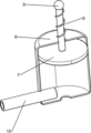
Fig. 2 is a schematic perspective view of the water spray assembly of the present invention.
FIG. 3 is a schematic perspective view of the present invention A.
Fig. 4 is a schematic perspective view of a portion of the present invention.
Part names and serial numbers in the figure: the automatic water-saving device comprises a mounting frame, 2 wheels, 3 pushing hands, 4 water storage cylinders, 5 connecting pipes, 6 cylinders, 7 pistons, 8 pushing rods, 9 first springs, 10 water outlet pipes, 11 speed reducing motors, 12 sector gears, 13 racks, 14 arc-shaped guide rails, 15 sliding blocks, 16 connecting rods, 161 oscillating bars, 162 torsion springs, 17 wedge-shaped blocks, 18L-shaped rods, 19 hollow frames, 20I-shaped openings, 21 baffles, 22 guide rods, 23 sliding sleeves, 231 second springs, 24 spray heads, 25 telescopic rods and 26V-shaped guide rails.
Detailed Description
The technical scheme of the invention is further explained by combining the attached drawings.
Example 1
The utility model provides a heatstroke prevention dust removal watering device for construction, as shown in fig. 1-4, including mounting bracket 1, the wheel 2, the pushing hands 3, a water storage section of thick bamboo 4, the water spray subassembly, power component and swing subassembly, the symmetry is equipped with four wheels 2 around mounting bracket 1 bottom, the welding of 1 right side of mounting bracket has pushing hands 3, the welding of 1 middle part of mounting bracket has a water storage section of thick bamboo 4, 4 tops of water storage section of thick bamboo are equipped with the water spray subassembly that carries out the water spray through the mode that promotes, 4 top right sides of water storage section of thick bamboo are equipped with the power component that provides power through the pivoted mode, 1 top left side of mounting bracket is equipped with carries out wobbling swing subassembly through the pivoted mode.
When using this equipment, the staff pours water into in water storage section of thick bamboo 4, pours into sufficient water back, and the staff promotes equipment to appointed place through pushing hands 3, opens power component afterwards and drives the subassembly that sprays water and spray water, and when the water spraying, rotating assembly can make the scope of equipment water spraying wider, and after the water spraying was accomplished, the staff closed power component.
As shown in fig. 1 and 2, the water spraying assembly comprises a connecting pipe 5, a cylinder body 6, a piston 7, a push rod 8, a first spring 9 and a water outlet pipe 10, the cylinder body 6 is welded at the top of a water storage cylinder 4, the connecting pipe 5 with a one-way valve is connected between the cylinder body 6 and the water storage cylinder 4, the piston 7 is arranged in the cylinder body 6 in a sliding mode, the push rod 8 is welded at the top of the piston 7, the push rod 8 penetrates through the middle of the top of the cylinder body 6, the first spring 9 is wound between the push rod 8 and the cylinder body 6, and the water outlet pipe 10 with the one-way valve is welded at the lower part of the left side of the cylinder body 6.
When spraying water, the staff opens power component and promotes piston 7 through push rod 8 and push into water blowout in outlet pipe 10 with the water lapse in cylinder body 6, and first spring 9 is compressed, and when first spring 9 reset, push rod 8 drives piston 7 thereupon and upwards slides and pass through connecting pipe 5 with the water in the water storage section of thick bamboo 4 and inhale cylinder body 6 in, and after the water spray was accomplished, the staff closed power component.
As shown in fig. 1, the power assembly comprises a speed reduction motor 11, a sector gear 12 and a rack 13, the speed reduction motor 11 is fixedly connected to the right side of the top of the mounting frame 1 through a bolt, the sector gear 12 is connected to an output shaft of the speed reduction motor 11 through a key, the rack 13 is welded to the right side of the push rod 8, and the rack 13 is meshed with the sector gear 12.
When spraying water, the staff starts gear motor 11 and drives sector gear 12 and rotate, when sector gear 12 rotated to mesh with rack 13, sector gear 12 rotated and drives rack 13 and move down, push rod 8 drives piston 7 and moves down with it and sprays water, first spring 9 is compressed, when sector gear 12 rotated to break away from with rack 13, under the effect that first spring 9 resets, push rod 8 moves up with it and resets, rack 13 moves up with it resets, after the water spray was accomplished, the staff closed gear motor 11 can.
As shown in fig. 1 and 3, the swing assembly comprises an arc-shaped guide rail 14, a sliding block 15, a connecting rod 16, a swing rod 161, a torsion spring 162, a wedge-shaped block 17 and an L-shaped rod 18, the arc-shaped guide rail 14 is welded on the left side of the top of the mounting rack 1, the sliding block 15 is arranged in the arc-shaped guide rail 14 in a sliding manner, the right portion of the water outlet pipe 10 is connected with the sliding block 15, the connecting rod 16 is arranged on the right side of the arc-shaped guide rail 14, the swing rod 161 is rotatably arranged on the connecting rod 16, the left end of the swing rod 161 is rotatably connected with the sliding block 15, the torsion spring 162 is wound between the swing rod 161 and the connecting rod 16, the wedge-shaped block 17 is welded on the right end of the swing rod 161, and the L-shaped rod 18 is welded on the left side of the push rod 8.
When water is sprayed, the push rod 8 moves downwards to drive the L-shaped rod 18 to move downwards, when the L-shaped rod 18 moves downwards to be in contact with the wedge-shaped block 17, the L-shaped rod 18 moves downwards to push the wedge-shaped block 17 to move forwards, thereby pushing the right end of the swing link 161 to swing forwards, the left end of the swing link 161 to swing backwards, the slide block 15 then slides backwards on the arc-shaped guide rail 14, the water outlet pipe 10 then swings backwards, the torsion spring 162 is compressed, when the push rod 8 moves upwards, the L-shaped rod 18 moves upwards along with the push rod and does not push the wedge block 17 any more, under the action of the reset of the torsion spring 162, the right end of the swing rod 161 swings backwards to reset, the wedge block 17 moves backwards to reset, the left end of the swing rod 161 swings forwards to reset, the sliding block 15 slides forwards in the arc-shaped guide rail 14 to reset, and the water outlet pipe 10 swings forwards to reset.
Example 2
On the basis of embodiment 1, as shown in fig. 1 and 4, the water storage device further includes a hollow frame 19, a baffle 21, a guide rod 22, a sliding sleeve 23, a second spring 231, a nozzle 24, a telescopic rod 25 and a V-shaped guide rail 26, the hollow frame 19 is welded at the left end of the water outlet pipe 10, a straight opening 20 is formed in the middle of the left side of the hollow frame 19, the baffle 21 is slidably arranged at the left side of the hollow frame 19, the guide rod 22 is welded at the bottom of the hollow frame 19, the sliding sleeve 23 is slidably arranged on the guide rod 22, the second spring 231 is wound between the sliding sleeve 23 and the hollow frame 19, the lower portion of the right side of the baffle 21 is connected with the sliding sleeve 23, the nozzle 24 is welded at the left side of the baffle 21, the telescopic rod 25 is welded at the right side of the sliding sleeve 23, the V-shaped guide rail 26 is welded at the upper portion of the left side of the water storage cylinder 4, and the right portion of the telescopic rod 25 is slidably located in the V-shaped guide rail 26.
When water is sprayed, the water outlet pipe 10 swings back and forth to drive the hollow frame 19 to swing back and forth, the baffle 21 swings back and forth along with the water outlet pipe, the spray head 24 swings back and forth along with the water outlet pipe to spray water, the baffle 21 swings back and forth to drive the telescopic rod 25 to move back and forth, the telescopic rod 25 slides up and down in the V-shaped guide rail 26 while moving back and forth, the baffle 21 slides up and down along with the baffle, the sliding sleeve 23 slides up and down in the guide rod 22 along with the sliding sleeve, the second spring 231 is compressed and reset along with the sliding sleeve, and the baffle 21 can prevent water from flowing out through the I-shaped opening 20 when sliding up and down, so that the water can be sprayed to a construction site more comprehensively.
The technical principle of the embodiment of the present invention is described above in conjunction with the specific embodiments. The description is only intended to explain the principles of embodiments of the invention and should not be taken in any way as limiting the scope of the embodiments of the invention. Based on the explanations herein, those skilled in the art will be able to conceive of other embodiments of the present invention without inventive step, and these embodiments will fall within the scope of the present invention.
Claims (1)
1. The utility model provides a heatstroke prevention dust removal watering device for construction, which comprises:
a mounting frame;
at least two wheels are symmetrically arranged on the mounting rack;
the push handle is arranged on the mounting rack;
the water storage cylinder is arranged on the mounting frame;
the water spraying component is arranged on the water storage cylinder and sprays water in a pushing mode;
the power assembly is arranged on the water storage cylinder and provides power in a rotating mode;
the swinging assembly is arranged on the mounting frame and swings in a rotating mode;
the water spray component comprises:
the connecting pipe is provided with a one-way valve and is arranged between the water storage cylinder and the cylinder body;
the cylinder body is arranged on the water storage cylinder;
the piston is slidably arranged in the cylinder body;
a push rod mounted on the piston;
the first spring is arranged between the push rod and the cylinder body;
the water outlet pipe is arranged on the cylinder body;
the power assembly comprises:
the speed reducing motor is arranged on the mounting frame;
the sector gear is arranged on an output shaft of the speed reducing motor;
the rack is arranged on the push rod and meshed with the sector gear;
the swing assembly comprises:
the arc-shaped guide rail is arranged on the mounting rack;
the sliding block is arranged in the arc-shaped guide rail in a sliding manner;
the connecting rod is arranged on the arc-shaped guide rail;
the swing rod is rotatably arranged on the connecting rod;
the torsion spring is arranged between the oscillating bar and the connecting rod;
the wedge-shaped block is arranged on the swing rod;
the L-shaped rod is arranged on the push rod;
also includes:
the hollow frame body is arranged on the water outlet pipe, and a straight opening is formed in the hollow frame body;
the baffle is arranged on the hollow frame in a sliding manner;
the guide rod is arranged on the hollow frame body;
the sliding sleeve is arranged on the guide rod in a sliding manner;
the second spring is arranged between the sliding sleeve and the hollow frame body;
the spray head is arranged on the baffle plate;
the telescopic rod is arranged on the sliding sleeve;
the V-shaped guide rail is arranged on the water storage barrel, and the right part of the telescopic rod is slidably positioned in the V-shaped guide rail.
Priority Applications (1)
| Application Number | Priority Date | Filing Date | Title |
|---|---|---|---|
| CN202010603120.6A CN111686538B (en) | 2020-06-29 | 2020-06-29 | Heatstroke prevention dust removal watering device for construction |
Applications Claiming Priority (1)
| Application Number | Priority Date | Filing Date | Title |
|---|---|---|---|
| CN202010603120.6A CN111686538B (en) | 2020-06-29 | 2020-06-29 | Heatstroke prevention dust removal watering device for construction |
Publications (2)
| Publication Number | Publication Date |
|---|---|
| CN111686538A CN111686538A (en) | 2020-09-22 |
| CN111686538B true CN111686538B (en) | 2021-11-23 |
Family
ID=72484300
Family Applications (1)
| Application Number | Title | Priority Date | Filing Date |
|---|---|---|---|
| CN202010603120.6A Active CN111686538B (en) | 2020-06-29 | 2020-06-29 | Heatstroke prevention dust removal watering device for construction |
Country Status (1)
| Country | Link |
|---|---|
| CN (1) | CN111686538B (en) |
Families Citing this family (7)
| Publication number | Priority date | Publication date | Assignee | Title |
|---|---|---|---|---|
| CN112243840A (en) * | 2020-10-14 | 2021-01-22 | 刘岩 | Corridor greening cultivation device |
| CN112244584B (en) * | 2020-10-21 | 2022-06-10 | 江西天晟金属设备有限公司 | Storage rack convenient to multi-functional decoration |
| CN112814705B (en) * | 2021-01-04 | 2023-09-08 | 成都铁路工程总承包有限责任公司 | Wall watering maintenance device for tunnel construction |
| CN113457328B (en) * | 2021-08-05 | 2022-10-14 | 湖南省煤业集团黄牛岭矿业有限公司 | Mine rubble dust device |
| CN114377496A (en) * | 2021-12-18 | 2022-04-22 | 刘新红 | Roadside dust removal device powered by solar energy |
| CN114345053B (en) * | 2022-01-04 | 2023-05-23 | 江西财经大学 | Heatstroke prevention, dust removal and water sprinkling device for building construction |
| CN114433380B (en) * | 2022-01-18 | 2023-08-04 | 郭军莲 | An environment-friendly microbial spraying device for rivers |
Citations (10)
| Publication number | Priority date | Publication date | Assignee | Title |
|---|---|---|---|---|
| DE2209453A1 (en) * | 1972-02-29 | 1973-09-13 | Willi Guggenbuehler | SPRAY AND FLOATING DEVICE FOR STREET CLEANING VEHICLES |
| CN105879529A (en) * | 2016-06-25 | 2016-08-24 | 马晓璐 | Effective dust collecting device for mining |
| CN205636607U (en) * | 2016-03-29 | 2016-10-12 | 温州红旭市政工程建设有限公司 | Bridge is with water spray heat sink |
| CN205628370U (en) * | 2016-05-12 | 2016-10-12 | 青岛建安建设集团有限公司 | Building site removes dust and uses high -efficient water jet equipment |
| CN106522144A (en) * | 2016-12-01 | 2017-03-22 | 朱雪梅 | Construction site dust removing device used for preventing fog and haze |
| CN206368341U (en) * | 2016-11-30 | 2017-08-01 | 中国建筑第二工程局有限公司 | Watering dustproof device for construction site |
| CN107487251A (en) * | 2017-08-29 | 2017-12-19 | 宣城市万成机械科技有限公司 | A kind of adjustable efficiently watering device for building |
| CN207126285U (en) * | 2017-08-09 | 2018-03-23 | 仲淑英 | A kind of efficient watering dust collecting device for building |
| CN108385592A (en) * | 2018-02-23 | 2018-08-10 | 肖灵芝 | A kind of municipal works urban road watering humidification apparatus |
| CN209816758U (en) * | 2019-01-21 | 2019-12-20 | 姜云铧 | Construction dust suppression device that multi-environment used |
Family Cites Families (13)
| Publication number | Priority date | Publication date | Assignee | Title |
|---|---|---|---|---|
| ITMI20012052A1 (en) * | 2001-10-03 | 2003-04-03 | Hi Tech Internat S R L | PROCEDURE FOR THE CAPITATION AND ABATEMENT OF VOLATILE POWDERS |
| JP3971991B2 (en) * | 2002-12-03 | 2007-09-05 | 株式会社日立産機システム | Air shower device |
| CN202238403U (en) * | 2011-08-31 | 2012-05-30 | 常州亚美柯机械设备有限公司 | Spraying machine |
| CN206024967U (en) * | 2016-06-27 | 2017-03-22 | 王成 | Laxative machine shower nozzle that can sway automatically |
| CN206186353U (en) * | 2016-10-04 | 2017-05-24 | 杨鹏 | Effective even heating device of pyrocondensation |
| CN206262742U (en) * | 2016-11-30 | 2017-06-20 | 河南路太养路机械股份有限公司 | A kind of remote-controlled universal water pistol |
| CN207228577U (en) * | 2017-08-04 | 2018-04-13 | 南京华夏天成建设有限公司 | A kind of finishing grey processing equipment early period of wall batch |
| CN207419357U (en) * | 2017-11-17 | 2018-05-29 | 南阳市油田天鹏建筑工程有限公司 | A kind of building engineering construction dust-extraction unit |
| CN108356012B (en) * | 2018-01-26 | 2020-08-04 | 晖腾工业科技有限公司 | Trees leaf cleaning equipment is used in gardens |
| CN208911032U (en) * | 2018-03-15 | 2019-05-31 | 兰州大学第一医院 | A kind of medical contagious department disinfectant liquid atomization flusher |
| CN208202618U (en) * | 2018-04-11 | 2018-12-07 | 崔洪武 | A kind of civil construction sprinkler |
| CN209668799U (en) * | 2019-01-24 | 2019-11-22 | 赵荣荣 | A kind of drug delivery device for treatment tank |
| CN110075641B (en) * | 2019-05-13 | 2021-05-14 | 安徽诺乐知识产权服务有限公司 | Building site sprays dust fall system |
-
2020
- 2020-06-29 CN CN202010603120.6A patent/CN111686538B/en active Active
Patent Citations (10)
| Publication number | Priority date | Publication date | Assignee | Title |
|---|---|---|---|---|
| DE2209453A1 (en) * | 1972-02-29 | 1973-09-13 | Willi Guggenbuehler | SPRAY AND FLOATING DEVICE FOR STREET CLEANING VEHICLES |
| CN205636607U (en) * | 2016-03-29 | 2016-10-12 | 温州红旭市政工程建设有限公司 | Bridge is with water spray heat sink |
| CN205628370U (en) * | 2016-05-12 | 2016-10-12 | 青岛建安建设集团有限公司 | Building site removes dust and uses high -efficient water jet equipment |
| CN105879529A (en) * | 2016-06-25 | 2016-08-24 | 马晓璐 | Effective dust collecting device for mining |
| CN206368341U (en) * | 2016-11-30 | 2017-08-01 | 中国建筑第二工程局有限公司 | Watering dustproof device for construction site |
| CN106522144A (en) * | 2016-12-01 | 2017-03-22 | 朱雪梅 | Construction site dust removing device used for preventing fog and haze |
| CN207126285U (en) * | 2017-08-09 | 2018-03-23 | 仲淑英 | A kind of efficient watering dust collecting device for building |
| CN107487251A (en) * | 2017-08-29 | 2017-12-19 | 宣城市万成机械科技有限公司 | A kind of adjustable efficiently watering device for building |
| CN108385592A (en) * | 2018-02-23 | 2018-08-10 | 肖灵芝 | A kind of municipal works urban road watering humidification apparatus |
| CN209816758U (en) * | 2019-01-21 | 2019-12-20 | 姜云铧 | Construction dust suppression device that multi-environment used |
Also Published As
| Publication number | Publication date |
|---|---|
| CN111686538A (en) | 2020-09-22 |
Similar Documents
| Publication | Publication Date | Title |
|---|---|---|
| CN111686538A (en) | Heatstroke prevention dust removal watering device for construction | |
| CN104775379A (en) | High-altitude bridge wall surface cleaning vehicle | |
| CN107761625A (en) | A kind of bilateral Cleaning vehicle for guardrail | |
| CN214939780U (en) | Road cleaning and watering equipment | |
| CN101650144B (en) | Air cooling condenser high-pressure door type or cantilever type track automatic cleaning device | |
| CN216218647U (en) | Spraying device is administered to mine geological environment | |
| CN208472631U (en) | A kind of novel retractable guardrail friction scrubbing apparatus | |
| CN109291888B (en) | Working method of building site car washing device capable of being cleaned in rotating mode | |
| CN213892839U (en) | Ship bottom cleaning robot | |
| CN210966061U (en) | A pillar insulator cleaning machine | |
| CN205934807U (en) | Be applied to guardrail cleaning vehicle's mechanism of washhing | |
| CN222999216U (en) | Deep foundation pit lattice column cleaning device | |
| CN206951672U (en) | A kind of automatic half rotary cleaning device | |
| CN106192830B (en) | A kind of Cleaning vehicle for guardrail | |
| CN216734217U (en) | Building site vehicle tire cleaning device | |
| CN212550827U (en) | Power plant generating set thrust tile belt cleaning device | |
| CN221773011U (en) | A cleaning device with adjustment function | |
| CN210753931U (en) | A catenary insulator cleaning device | |
| CN201463706U (en) | Air cooling condenser high pressure door type or suspension arm type orbit automatic cleaning device | |
| CN113828559A (en) | Energy-concerving and environment-protective solar panel clearance machine | |
| CN205934806U (en) | Small -size road maintenance washs car | |
| CN219339413U (en) | On-spot ash removal equipment of dregs car dress soil | |
| CN215530583U (en) | Bridge is with multi-functional sprinkler of high-efficient saving | |
| CN222139702U (en) | Auxiliary road pressing device for building construction | |
| CN216331942U (en) | An efficient gantry car washer |
Legal Events
| Date | Code | Title | Description |
|---|---|---|---|
| PB01 | Publication | ||
| PB01 | Publication | ||
| SE01 | Entry into force of request for substantive examination | ||
| SE01 | Entry into force of request for substantive examination | ||
| CB03 | Change of inventor or designer information | ||
| CB03 | Change of inventor or designer information |
Inventor after: Zheng Zishuo Inventor after: Ma Pengfei Inventor before: Ma Pengfei |
|
| TA01 | Transfer of patent application right | ||
| TA01 | Transfer of patent application right |
Effective date of registration: 20211108 Address after: 475001 Henan University, No. 85, Minglun street, Kaifeng City, Henan Province Applicant after: Zheng Zishuo Address before: 330000 Room 301, No. 97, middle Nangang Road, Luojia Town, suburb, Qingshanhu District, Nanchang City, Jiangxi Province Applicant before: Ma Pengfei |
|
| GR01 | Patent grant | ||
| GR01 | Patent grant |