EP1300088A2 - A cigarette maker outfeed unit - Google Patents
A cigarette maker outfeed unit Download PDFInfo
- Publication number
- EP1300088A2 EP1300088A2 EP02425589A EP02425589A EP1300088A2 EP 1300088 A2 EP1300088 A2 EP 1300088A2 EP 02425589 A EP02425589 A EP 02425589A EP 02425589 A EP02425589 A EP 02425589A EP 1300088 A2 EP1300088 A2 EP 1300088A2
- Authority
- EP
- European Patent Office
- Prior art keywords
- cigarette rod
- unit
- feed path
- cut
- gripping
- Prior art date
- Legal status (The legal status is an assumption and is not a legal conclusion. Google has not performed a legal analysis and makes no representation as to the accuracy of the status listed.)
- Granted
Links
- 235000019504 cigarettes Nutrition 0.000 title claims abstract description 58
- 238000003908 quality control method Methods 0.000 description 11
- 241000208125 Nicotiana Species 0.000 description 8
- 235000002637 Nicotiana tabacum Nutrition 0.000 description 8
- 239000000945 filler Substances 0.000 description 5
- 230000007547 defect Effects 0.000 description 3
- 239000012634 fragment Substances 0.000 description 3
- 238000004519 manufacturing process Methods 0.000 description 1
- 239000002245 particle Substances 0.000 description 1
Images


Classifications
-
- A—HUMAN NECESSITIES
- A24—TOBACCO; CIGARS; CIGARETTES; SIMULATED SMOKING DEVICES; SMOKERS' REQUISITES
- A24C—MACHINES FOR MAKING CIGARS OR CIGARETTES
- A24C5/00—Making cigarettes; Making tipping materials for, or attaching filters or mouthpieces to, cigars or cigarettes
- A24C5/14—Machines of the continuous-rod type
- A24C5/31—Machines of the continuous-rod type with special arrangements coming into operation during starting, slowing-down or breakdown of the machine, e.g. for diverting or breaking the continuous rod
Definitions
- the present invention relates to an outfeed unit in a cigarette maker.
- Machines for making cigarettes comprise a unit serving to shape and advance a continuous ribbon of tobacco filler drawn from a tobacco feeder device, and a unit serving to feed a continuous strip of paper which is directed onto and along a forming beam and wrapped progressively around the ribbon of tobacco filler to form a continuous cigarette rod.
- the cigarette rod On reaching an outfeed unit of the machine, the cigarette rod is advanced along a predetermined feed path at a predetermined speed, passing through a succession of quality control devices and into a cutting station where it is divided into cigarette sticks of predetermined length by a rotary cutter device.
- the cut-off device in question is interlocked to the aforementioned quality control devices and will be activated in the event of the selfsame devices detecting properties or defects in the cigarette rod such as render it unsuitable for the production of single cigarettes.
- the length of cigarette rod remaining between the selfsame cut-off device and the rotary cutter must be removed manually so that normal operation of the machine can be resumed.
- the task of removing this fragment of cigarette rod is a complex one, since besides opening up the casing of the machine it may also be necessary to disturb the quality control devices, dismantling them in part and occasioning lengthy periods of inactivity as a result.
- the object of the present invention is to provide an outfeed unit for a cigarette maker such as will be unaffected by the aforementioned drawbacks.
- a cigarette maker outfeed unit comprising a feed path along which at least one cigarette rod is advanced in a predetermined direction, extending between the outfeed end of a beam on which the cigarette rod is formed and a cutter device by which the continuous cigarette rod is divided into discrete sticks constituting single cigarettes, also a cut-off device positioned in close proximity to the forming beam and capable of movement between a position of disengagement from the feed path, and a position of interference with the selfsame path in which the rod is cut and diverted from the path, characterized in that it comprises removal means by which a portion of the continuous cigarette rod separated through the action of the cut-off device is distanced from a final stretch of the feed path extending between the cut-off device and the cutter device.
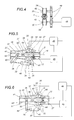
- FIG. 1 denotes a portion, in its entirety, of a machine serving to fashion a continuous cigarette rod 2.
- the machine 1 is equipped with an outfeed unit denoted 3 in its entirety, which comprises an aspirating conveyor belt 4 looped around two pulleys 5 positioned one at either end (one only of which is illustrated in figure 1) and rotatable clockwise, as viewed in the drawing, about mutually parallel horizontal axes 6.
- the endless loop described by the conveyor belt 4 compasses a chamber 7 connected to a source of negative pressure (not illustrated) and delimited at the bottom by a wall 8 pierced with suction holes 9.
- the bottom branch 10 of the conveyor belt 4 runs in sliding contact with the wall 8 and is able to retain the particles 11 of tobacco by suction as they emerge from a riser (not illustrated) located beneath the branch 10, thus forming a continuous ribbon 12 of tobacco.
- the ribbon 12 is directed by the branch 10 of the belt 4 in a substantially horizontal direction 13, transverse to the axis 6 of the pulley 5, onto a feed path 14 running through a station 15 at which the continuous cigarette rod 2 is formed.
- the forming station 15 is occupied by a running strip 16 of paper, directed along the feed path 14, which is decoiled by a relative feeder unit 17 from a roll 18 through the action of a pair of pinch wheels 19.
- the decoiling strip 16 is taken around a pulley 20 and routed toward the forming station 15, which incorporates a belt conveyor 21 capable of retaining the strip 16 of paper by suction and advancing it along the feed path 14 together with the ribbon 12 of tobacco filler released onto the strip 16 by the bottom branch 10 of the conveyor belt 4.
- the forming station 15 also comprises a beam 22 of conventional embodiment extending along the feed path 14, of which the function is to wrap the paper strip 16 around the ribbon 12 of tobacco filler.
- the two longitudinal edges of the strip 16 are overlapped gradually along the beam 22 and glued together (in a conventional manner not indicated), thereby generating the aforementioned continuous cigarette rod 2.
- the feed path 14 extends beyond the beam 22 and along a feed direction 23 followed by the rod 2 toward a cutting station 24, at which a rotating cutter device 25 divides the continuous rod 2 into discrete cigarette sticks 26 of predetermined and constant length.
- the feed path 14 presents a final stretch 14a between the beam 22 and the cutting station 24, coinciding with a table 27 along which the rod 2 is guided, and including a quality control device 28 by which the cigarette rod 2 is scanned in order to verify that it is correctly formed, and to reveal any possible defects.
- a cut-off device 29 comprising a blade 30 capable of movement between a raised first position of disengagement from the feed path 14a, illustrated in figure 1, and a second position of interference with the feed path 14, illustrated in figure 2, in which the cigarette rod 2 is diverted by the device 29 toward a reject station 31, having been cut during the passage of the blade from the first to the second position.
- the cut-off device 29 can come into operation either when the machine 1 is started up and shut down, or whenever a defect is detected in the cigarette rod 2 by the quality control device 28, to which the cut-off device 29 is interlocked.
- the outfeed unit 3 further comprises means 32, located between the cutting station 24 and the quality control station 28, of which the function is to remove a portion 2a of the cigarette rod 2 that may be left on the final stretch 14a of the feed path 14, which extends from the cut-off device 29 to the rotary cutter device 25, following the operation of the cut-off device 29.
- the removal means 32 comprise gripping and feeding means 33 by which the aforementioned portion 2a of cigarette rod 2 is taken up and advanced along the final stretch 14a of the feed path 14.
- the gripping and feeding means 33 comprise a pair of rollers 34 positioned one on either side of the final stretch 14a of the feed path 14 and mounted to respective mutually parallel shafts 35 extending transversely to the path 14.
- rollers 34 are mounted to respective shafts 35 carried in turn by the jaws 36 of a gripper 37 centred on a pivot denoted 38.
- the gripper 37 is operated by respective drive means 39 comprising a lever 40 of which one end carries a pair of cams 41 acting on the gripper 37 by engagement with the free ends 42 of the jaws 36, on either side of the pivot 38.
- the remaining end of the lever 40 is connected to relative actuator means 43, consisting in a cylinder, by which the jaws 36 are opened and closed through the agency of the lever 40, the cams 41 and the free ends 42.
- the rollers 34 are rendered capable thus of movement between a first non-operating position spread apart as illustrated in figure 5, and a second operating position, drawn together as illustrated in 6, in which they combine to create a passage coinciding with a break 44 in the table 27 and presenting a transverse dimension substantially equal to the transverse dimension of the cigarette rod 2.
- the rollers 34 are driven by a motor indicated by a block denoted 45, and set in rotation in opposite directions so that the portion 2a of the cigarette rod 2 is caused to advance in the aforementioned direction 23 toward the rotary cutter device 25.
- the gripper actuator 43, the motor 45 and cutter device 25 are interlocked to a master control unit 46 which in turn is connected to the quality control device 28.
- the unit 46 On receiving a signal from the quality control device 28, the unit 46 will pilot the actuator 43 to draw the rollers 34 closer together and activate the motor 45 to set them in rotation about the respective shafts 35, while causing the cutter device 25 (in the example of figure 2) to rotate at a prescribed frequency generally higher than during normal operation so as to chop up the portion 2a of the cigarette rod 2 advanced toward the device 25 by the rollers 34.
- the fragments of cigarette rod thus produced are diverted toward a reject station, indicated as a block denoted 47, by means of a movable flap 52 forming part of the table 27 and able to pivot about an axis transverse to the feed path 14, between a raised position of substantial alignment with the plane occupied by the table 27 (figure 1) and a lowered position (figure 2) in which the fragments of cigarette rod are diverted away.
- rollers 34 are located between the cut-off blade 30 and the quality control device 28, rather than beyond this selfsame device 28.
- the motor 45 will be piloted to rotate the rollers 34 in the direction opposite to that described previously, so that the portion 2a of cigarette rod 2 is taken up and advanced along the final stretch 14a of the feed path 14 in the direction opposite to the predetermined direction denoted 23 toward the cut-off device 29, which will then divert the portion 2a of rod toward the reject station 31.
- the surface 29a of the cut-off device 29 directed toward the rollers 34 is fashioned in such a way as to provide an effective diverting element by means of which to guide the portion 2a of rod 2 toward the reject station 31.
- the two rollers 34 of the gripping and feeding means 33 are mounted to respective shafts 35 with respective fixed parallel axes 48 by which the rollers are carried in a fixed position, corresponding to the operating position described previously, and in which they combine to create a passage coinciding with a break 44 in the table 27 and presenting a transverse dimension substantially equal to the transverse dimension of the cigarette rod 2.
- the motor 45 is coupled to a pair of gear wheels 49, engaged in constant mesh, which during normal operation of the machine 1 will drive the rollers 34 at a tangential velocity identical to the linear velocity of the advancing rod 2.
- the unit comprises pneumatic means 50 located along the final stretch 14a of the feed path 14, by which a flow of pressurized air can be directed along the path 14 to eliminate any residual paper and tobacco filler.
- the outfeed unit 3 described above might incorporate any number of variations without straying from the spirit of the present invention.
- the shafts 35 of the rollers 34 can be oriented in any given direction, provided they are disposed transversely to the feed path 14.
- the relative outfeed unit embodied in accordance with the invention, will include a pair of rollers 34 for each one of the two rods.
Landscapes
- Manufacturing Of Cigar And Cigarette Tobacco (AREA)
- Wrapping Of Specific Fragile Articles (AREA)
Abstract
Description
- figure 1 shows an outfeed unit of a cigarette maker, embodied in accordance with the present invention, viewed schematically in a side elevation with certain parts in section and others omitted for clarity;
- figure 2 is an enlarged detail of figure 1, viewed schematically in a side elevation and with certain parts omitted for clarity;
- figure 3 shows the enlarged detail of figure 2 in a second possible embodiment, viewed schematically in a side elevation and with certain parts omitted for clarity;
- figures 4 and 5 show a detail of the unit as in figure 1 illustrated in two different embodiments, viewed schematically in front elevation and side elevation, respectively, and with certain parts omitted for clarity;
- figure 6 illustrates the detail of figure 5 in a different operating position.
Claims (11)
- A cigarette maker outfeed unit, comprising a feed path (14) along which at least one cigarette rod (2) is caused to advance in a predetermined direction (23), extending between the outfeed end of a beam (22) on which the cigarette rod (2) is formed and a cutter device (25) by which the continuous cigarette rod is divided into discrete sticks (26) constituting single cigarettes, also a cut-off device (29) positioned in close proximity to the forming beam (22) and capable of movement between a position of disengagement from the feed path (14), and a position of interference with the selfsame path in which the rod (2) is cut and diverted from the path (14), characterized in that it comprises removal means (32) by which a portion of the continuous cigarette rod (2) separated through the action of the cut-off device (29) is distanced from a final stretch (14a) of the feed path (14) extending between the cut-off device (29) and the cutter device (25).
- A unit as in claim 1, wherein removal means (32) comprise gripping and feeding means (33) by which the portion of cigarette rod (2) is taken up and advanced along the final stretch (14a) of the feed path (14).
- A unit as in claim 2, wherein the gripping and feeding means (33) are designed to direct the portion of cigarette rod (2) in the predetermined direction (23) toward the cutter device (25), operating in conjunction with the selfsame cutter device (25) to remove the portion of cigarette rod from the final stretch (14a) of the feed path (14).
- A unit as in claim 3, wherein the gripping and feeding means (33) are interlocked to master control means (46) such as will pilot the selfsame gripping and feeding means (33) to operate at a predetermined feed velocity.
- A unit as in claim 2, wherein the gripping and feeding means (33) are designed to advance the portion of cigarette rod (2) along the final stretch (14a) of the feed path (14) in a direction opposite to the predetermined direction (23) and toward the cut-off device (29), operating in conjunction with the cutter device (25) to remove the portion of cigarette rod (2) from the final stretch (14a) of the feed path (14) and divert it toward a reject station (31).
- A unit as in claim 2, wherein the gripping and feeding means (33) comprise two contrarotating rollers (34) disposed on opposite sides of the feed path (14) and mounted to respective shafts (35) of which the axes extend transversely to the selfsame feed path (14).
- A unit as in claim 6, wherein the two rollers (34) occupy fixed positions in which they combine to afford a passage presenting a transverse dimension substantially equal to the transverse dimension of the cigarette rod (2), and are caused to rotate at least during normal operation of the cigarette maker (1) at a tangential velocity substantially identical to the linear velocity of the cigarette rod (2) advancing along the feed path (14).
- A unit as in claim 6, wherein the two rollers (34) are capable of movement between a non-operating position, spread apart, and an operating position, drawn closer together, in which they combine to afford a passage presenting a transverse dimension substantially equal to the transverse dimension of the cigarette rod (2).
- A unit as in claim 8, wherein the rollers (34) are mounted to respective shafts (35) carried by the jaws (36) of a gripper (37) operated though the agency of means (40, 41) serving to open and close the jaws (36), which are set in motion by relative actuator means (43) interlocked to master control means (46).
- A unit as in claims 6 to 9, wherein the surface of revolution presented by each of the rollers (34) and offered in contact to the cigarette rod (2) presents a cross section of U-shaped profile.
- A unit as in claim 3, wherein the gripping and feeding means (33) and the cutter device (25) are interlocked to master control means (46) by which the gripping and feeding means (33) are made to operate at a predetermined feed velocity and the cutter device (25) is driven at a predetermined cutting frequency.
Applications Claiming Priority (2)
| Application Number | Priority Date | Filing Date | Title |
|---|---|---|---|
| IT2001BO000604A ITBO20010604A1 (en) | 2001-10-03 | 2001-10-03 | OUTPUT UNIT OF A CIGARETTE PACKING MACHINE |
| ITBO20010604 | 2001-10-03 |
Publications (3)
| Publication Number | Publication Date |
|---|---|
| EP1300088A2 true EP1300088A2 (en) | 2003-04-09 |
| EP1300088A3 EP1300088A3 (en) | 2005-06-08 |
| EP1300088B1 EP1300088B1 (en) | 2007-08-29 |
Family
ID=11439646
Family Applications (1)
| Application Number | Title | Priority Date | Filing Date |
|---|---|---|---|
| EP02425589A Expired - Lifetime EP1300088B1 (en) | 2001-10-03 | 2002-09-30 | A cigarette maker outfeed unit |
Country Status (6)
| Country | Link |
|---|---|
| US (1) | US6769435B2 (en) |
| EP (1) | EP1300088B1 (en) |
| JP (1) | JP4012030B2 (en) |
| AT (1) | ATE371381T1 (en) |
| DE (1) | DE60222069T2 (en) |
| IT (1) | ITBO20010604A1 (en) |
Cited By (4)
| Publication number | Priority date | Publication date | Assignee | Title |
|---|---|---|---|---|
| EP1449446A1 (en) * | 2003-02-20 | 2004-08-25 | G.D S.p.A. | A device and a method for separating at least one continuous rod of forming material for tobacco products |
| WO2006111812A1 (en) * | 2005-04-19 | 2006-10-26 | G.D S.P.A. | A method of managing a machine for manufacturing tobacco products |
| EP2258220A1 (en) * | 2009-06-06 | 2010-12-08 | Hauni Maschinenbau AG | Cutting device for the tobacco industry for cutting at least one transported strand into a number of rod-shaped articles and method for setting up and testing the cutting device |
| EP2263483A1 (en) * | 2009-06-06 | 2010-12-22 | Hauni Maschinenbau AG | Cutting device for the tobacco industry for cutting at least one transported strand into a number of rod-shaped articles and method for disabling the cutting device |
Families Citing this family (5)
| Publication number | Priority date | Publication date | Assignee | Title |
|---|---|---|---|---|
| US6949622B2 (en) * | 2003-08-26 | 2005-09-27 | General Electric Company | Method of separating a polymer from a solvent |
| ITBO20050733A1 (en) * | 2005-12-01 | 2006-03-02 | Gd Spa | DEVICE AND PROCEDURE FOR THE TRANSFER OF SMOKE ARTICLES TO LOTS |
| DE102005062644A1 (en) * | 2005-12-23 | 2007-07-26 | Hauni Maschinenbau Ag | Cutting device and strand material removal device of the tobacco processing industry |
| PL215954B1 (en) * | 2010-08-13 | 2014-02-28 | Int Tobacco Machinery Poland | Method of manufacturing the multi-segment filter rods |
| PL234056B1 (en) * | 2017-07-07 | 2020-01-31 | Int Tobacco Machinery Poland Spolka Z Ograniczona Odpowiedzialnoscia | Method for producing multi-segment bars and method for cleaning a machine for production of multi-segment bars |
Family Cites Families (5)
| Publication number | Priority date | Publication date | Assignee | Title |
|---|---|---|---|---|
| FR2313875A1 (en) * | 1975-06-10 | 1977-01-07 | Molins Ltd | Cutter for continuous rod cigarette making machine - is block or roller which pulls rod down ahead of cutter blocks |
| FR2379260A1 (en) * | 1977-02-03 | 1978-09-01 | Arenco Decoufle Sa Fse | DEVICE SAID "SNACK" FOR CIGARETTE MAKING MACHINE |
| US4226352A (en) * | 1978-01-13 | 1980-10-07 | Molins Limited | Continuous-rod making machines |
| IT1133455B (en) * | 1980-07-11 | 1986-07-09 | Cir Spa Divisione Sasib | DEVICE FOR CUTTING AND CUTTING THE CONTINUOUS BACO IN CIGARETTE PACKAGING MACHINES |
| IT1171577B (en) * | 1981-10-08 | 1987-06-10 | Gd Spa | CUTTING DEVICE OF AT LEAST ONE CONTINUOUS CORD IN A SMOKE PRODUCT PACKAGING MACHINE |
-
2001
- 2001-10-03 IT IT2001BO000604A patent/ITBO20010604A1/en unknown
-
2002
- 2002-09-30 DE DE60222069T patent/DE60222069T2/en not_active Expired - Lifetime
- 2002-09-30 AT AT02425589T patent/ATE371381T1/en not_active IP Right Cessation
- 2002-09-30 EP EP02425589A patent/EP1300088B1/en not_active Expired - Lifetime
- 2002-10-02 JP JP2002289908A patent/JP4012030B2/en not_active Expired - Fee Related
- 2002-10-02 US US10/262,069 patent/US6769435B2/en not_active Expired - Fee Related
Cited By (7)
| Publication number | Priority date | Publication date | Assignee | Title |
|---|---|---|---|---|
| EP1449446A1 (en) * | 2003-02-20 | 2004-08-25 | G.D S.p.A. | A device and a method for separating at least one continuous rod of forming material for tobacco products |
| US7305994B2 (en) | 2003-02-20 | 2007-12-11 | G.D S.P.A. | Device and a method for separating at least one continuous rod of forming material for tobacco products |
| WO2006111812A1 (en) * | 2005-04-19 | 2006-10-26 | G.D S.P.A. | A method of managing a machine for manufacturing tobacco products |
| CN100588335C (en) * | 2005-04-19 | 2010-02-10 | 吉地股份公司 | Method of operating machinery for the manufacture of tobacco products |
| DE202006021018U1 (en) | 2005-04-19 | 2011-10-17 | G.D S.P.A. | Machine for the production of tobacco products |
| EP2258220A1 (en) * | 2009-06-06 | 2010-12-08 | Hauni Maschinenbau AG | Cutting device for the tobacco industry for cutting at least one transported strand into a number of rod-shaped articles and method for setting up and testing the cutting device |
| EP2263483A1 (en) * | 2009-06-06 | 2010-12-22 | Hauni Maschinenbau AG | Cutting device for the tobacco industry for cutting at least one transported strand into a number of rod-shaped articles and method for disabling the cutting device |
Also Published As
| Publication number | Publication date |
|---|---|
| EP1300088B1 (en) | 2007-08-29 |
| JP2003116513A (en) | 2003-04-22 |
| DE60222069D1 (en) | 2007-10-11 |
| ATE371381T1 (en) | 2007-09-15 |
| ITBO20010604A1 (en) | 2003-04-03 |
| EP1300088A3 (en) | 2005-06-08 |
| US6769435B2 (en) | 2004-08-03 |
| JP4012030B2 (en) | 2007-11-21 |
| US20030062054A1 (en) | 2003-04-03 |
| DE60222069T2 (en) | 2008-06-05 |
Similar Documents
| Publication | Publication Date | Title |
|---|---|---|
| US4694714A (en) | Process and apparatus for changing reels in connection with packaging machines | |
| CN1882256B (en) | A system for monitoring and controlling machines used in the manufacture of tobacco products | |
| JPH01226515A (en) | Device for packaging package with walnut material | |
| US4671152A (en) | Apparatus for cutting out windows in envelopes | |
| US4016708A (en) | Envelope processing machine | |
| US3982375A (en) | Process and a device for wrapping articles, more particularly, groups of cigarettes | |
| EP1300088B1 (en) | A cigarette maker outfeed unit | |
| JP3103553U (en) | A device that breaks the notch connecting both edges of the cutting line | |
| EP1642835A1 (en) | A unit for feeding and cutting into lengths a strip of wrapping material | |
| EP3197302B1 (en) | Machine for making smokers' articles | |
| CN1985688B (en) | Rod cutting device for the tobacco processing industry | |
| US7437982B2 (en) | Unit for feeding and cutting into lengths a strip of wrapping material | |
| JPH10218123A (en) | Apparatus for feeding walnut tape for groups of cigarettes or cigarette packages | |
| CN1317987C (en) | Device and a method for separating at least one continuous rod of forming material for tobacco products | |
| US2902040A (en) | Method and machine for manufacturing filter mouth piece cigarettes | |
| EP0974276B1 (en) | Cigarette manufacturing machine | |
| EP2543504B1 (en) | Device for processing packaging material for cigarette packets | |
| GB2082439A (en) | A cigarette rod-breaking device | |
| EP0976334B1 (en) | Cigarette manufacturing machine | |
| JP4945071B2 (en) | Apparatus and method for producing at least two fiber continuums | |
| JPH09105024A (en) | Device for splitting a card web into multiple length pieces | |
| WO1992021566A1 (en) | Bread unwrapping apparatus | |
| EP0545265B1 (en) | Method and device for feeding wrapping material to a wrapping machine | |
| JP3929661B2 (en) | Cutting device for sheet-like products | |
| JPH03162939A (en) | Device for manufacturing shoulder strip- like sheet for web-like material to be surfed to packaging device |
Legal Events
| Date | Code | Title | Description |
|---|---|---|---|
| PUAI | Public reference made under article 153(3) epc to a published international application that has entered the european phase |
Free format text: ORIGINAL CODE: 0009012 |
|
| AK | Designated contracting states |
Kind code of ref document: A2 Designated state(s): AT BE BG CH CY CZ DE DK EE ES FI FR GB GR IE IT LI LU MC NL PT SE SK TR Designated state(s): AT BE BG CH CY CZ DE DK EE ES FI FR GB GR IE IT LI LU MC NL PT SE SK TR |
|
| AX | Request for extension of the european patent |
Extension state: AL LT LV MK RO SI |
|
| PUAL | Search report despatched |
Free format text: ORIGINAL CODE: 0009013 |
|
| AK | Designated contracting states |
Kind code of ref document: A3 Designated state(s): AT BE BG CH CY CZ DE DK EE ES FI FR GB GR IE IT LI LU MC NL PT SE SK TR |
|
| AX | Request for extension of the european patent |
Extension state: AL LT LV MK RO SI |
|
| 17P | Request for examination filed |
Effective date: 20050721 |
|
| AKX | Designation fees paid |
Designated state(s): AT BE BG CH CY CZ DE DK EE ES FI FR GB GR IE IT LI LU MC NL PT SE SK TR |
|
| 17Q | First examination report despatched |
Effective date: 20061030 |
|
| GRAP | Despatch of communication of intention to grant a patent |
Free format text: ORIGINAL CODE: EPIDOSNIGR1 |
|
| GRAS | Grant fee paid |
Free format text: ORIGINAL CODE: EPIDOSNIGR3 |
|
| GRAA | (expected) grant |
Free format text: ORIGINAL CODE: 0009210 |
|
| AK | Designated contracting states |
Kind code of ref document: B1 Designated state(s): AT BE BG CH CY CZ DE DK EE ES FI FR GB GR IE IT LI LU MC NL PT SE SK TR |
|
| REG | Reference to a national code |
Ref country code: GB Ref legal event code: FG4D |
|
| REG | Reference to a national code |
Ref country code: CH Ref legal event code: EP |
|
| REG | Reference to a national code |
Ref country code: IE Ref legal event code: FG4D |
|
| REF | Corresponds to: |
Ref document number: 60222069 Country of ref document: DE Date of ref document: 20071011 Kind code of ref document: P |
|
| REG | Reference to a national code |
Ref country code: CH Ref legal event code: NV Representative=s name: BUGNION S.A. |
|
| PG25 | Lapsed in a contracting state [announced via postgrant information from national office to epo] |
Ref country code: NL Free format text: LAPSE BECAUSE OF FAILURE TO SUBMIT A TRANSLATION OF THE DESCRIPTION OR TO PAY THE FEE WITHIN THE PRESCRIBED TIME-LIMIT Effective date: 20070829 Ref country code: FI Free format text: LAPSE BECAUSE OF FAILURE TO SUBMIT A TRANSLATION OF THE DESCRIPTION OR TO PAY THE FEE WITHIN THE PRESCRIBED TIME-LIMIT Effective date: 20070829 Ref country code: ES Free format text: LAPSE BECAUSE OF FAILURE TO SUBMIT A TRANSLATION OF THE DESCRIPTION OR TO PAY THE FEE WITHIN THE PRESCRIBED TIME-LIMIT Effective date: 20071210 |
|
| NLV1 | Nl: lapsed or annulled due to failure to fulfill the requirements of art. 29p and 29m of the patents act | ||
| PG25 | Lapsed in a contracting state [announced via postgrant information from national office to epo] |
Ref country code: AT Free format text: LAPSE BECAUSE OF FAILURE TO SUBMIT A TRANSLATION OF THE DESCRIPTION OR TO PAY THE FEE WITHIN THE PRESCRIBED TIME-LIMIT Effective date: 20070829 |
|
| ET | Fr: translation filed | ||
| PG25 | Lapsed in a contracting state [announced via postgrant information from national office to epo] |
Ref country code: BE Free format text: LAPSE BECAUSE OF FAILURE TO SUBMIT A TRANSLATION OF THE DESCRIPTION OR TO PAY THE FEE WITHIN THE PRESCRIBED TIME-LIMIT Effective date: 20070829 |
|
| PG25 | Lapsed in a contracting state [announced via postgrant information from national office to epo] |
Ref country code: MC Free format text: LAPSE BECAUSE OF NON-PAYMENT OF DUE FEES Effective date: 20070930 Ref country code: GR Free format text: LAPSE BECAUSE OF FAILURE TO SUBMIT A TRANSLATION OF THE DESCRIPTION OR TO PAY THE FEE WITHIN THE PRESCRIBED TIME-LIMIT Effective date: 20071130 Ref country code: DK Free format text: LAPSE BECAUSE OF FAILURE TO SUBMIT A TRANSLATION OF THE DESCRIPTION OR TO PAY THE FEE WITHIN THE PRESCRIBED TIME-LIMIT Effective date: 20070829 |
|
| PG25 | Lapsed in a contracting state [announced via postgrant information from national office to epo] |
Ref country code: SK Free format text: LAPSE BECAUSE OF FAILURE TO SUBMIT A TRANSLATION OF THE DESCRIPTION OR TO PAY THE FEE WITHIN THE PRESCRIBED TIME-LIMIT Effective date: 20070829 Ref country code: PT Free format text: LAPSE BECAUSE OF FAILURE TO SUBMIT A TRANSLATION OF THE DESCRIPTION OR TO PAY THE FEE WITHIN THE PRESCRIBED TIME-LIMIT Effective date: 20080129 Ref country code: CZ Free format text: LAPSE BECAUSE OF FAILURE TO SUBMIT A TRANSLATION OF THE DESCRIPTION OR TO PAY THE FEE WITHIN THE PRESCRIBED TIME-LIMIT Effective date: 20070829 |
|
| PG25 | Lapsed in a contracting state [announced via postgrant information from national office to epo] |
Ref country code: SE Free format text: LAPSE BECAUSE OF FAILURE TO SUBMIT A TRANSLATION OF THE DESCRIPTION OR TO PAY THE FEE WITHIN THE PRESCRIBED TIME-LIMIT Effective date: 20071129 |
|
| PLBE | No opposition filed within time limit |
Free format text: ORIGINAL CODE: 0009261 |
|
| STAA | Information on the status of an ep patent application or granted ep patent |
Free format text: STATUS: NO OPPOSITION FILED WITHIN TIME LIMIT |
|
| 26N | No opposition filed |
Effective date: 20080530 |
|
| PG25 | Lapsed in a contracting state [announced via postgrant information from national office to epo] |
Ref country code: IE Free format text: LAPSE BECAUSE OF NON-PAYMENT OF DUE FEES Effective date: 20071001 |
|
| PG25 | Lapsed in a contracting state [announced via postgrant information from national office to epo] |
Ref country code: EE Free format text: LAPSE BECAUSE OF FAILURE TO SUBMIT A TRANSLATION OF THE DESCRIPTION OR TO PAY THE FEE WITHIN THE PRESCRIBED TIME-LIMIT Effective date: 20070829 |
|
| PG25 | Lapsed in a contracting state [announced via postgrant information from national office to epo] |
Ref country code: CY Free format text: LAPSE BECAUSE OF FAILURE TO SUBMIT A TRANSLATION OF THE DESCRIPTION OR TO PAY THE FEE WITHIN THE PRESCRIBED TIME-LIMIT Effective date: 20070829 |
|
| PG25 | Lapsed in a contracting state [announced via postgrant information from national office to epo] |
Ref country code: LU Free format text: LAPSE BECAUSE OF NON-PAYMENT OF DUE FEES Effective date: 20070930 Ref country code: BG Free format text: LAPSE BECAUSE OF FAILURE TO SUBMIT A TRANSLATION OF THE DESCRIPTION OR TO PAY THE FEE WITHIN THE PRESCRIBED TIME-LIMIT Effective date: 20071129 |
|
| PG25 | Lapsed in a contracting state [announced via postgrant information from national office to epo] |
Ref country code: TR Free format text: LAPSE BECAUSE OF FAILURE TO SUBMIT A TRANSLATION OF THE DESCRIPTION OR TO PAY THE FEE WITHIN THE PRESCRIBED TIME-LIMIT Effective date: 20070829 |
|
| PGFP | Annual fee paid to national office [announced via postgrant information from national office to epo] |
Ref country code: GB Payment date: 20090929 Year of fee payment: 8 Ref country code: CH Payment date: 20090925 Year of fee payment: 8 |
|
| PGFP | Annual fee paid to national office [announced via postgrant information from national office to epo] |
Ref country code: DE Payment date: 20090929 Year of fee payment: 8 |
|
| PG25 | Lapsed in a contracting state [announced via postgrant information from national office to epo] |
Ref country code: IT Free format text: LAPSE BECAUSE OF NON-PAYMENT OF DUE FEES Effective date: 20070930 |
|
| REG | Reference to a national code |
Ref country code: CH Ref legal event code: PL |
|
| GBPC | Gb: european patent ceased through non-payment of renewal fee |
Effective date: 20100930 |
|
| REG | Reference to a national code |
Ref country code: FR Ref legal event code: ST Effective date: 20110531 |
|
| REG | Reference to a national code |
Ref country code: DE Ref legal event code: R119 Ref document number: 60222069 Country of ref document: DE Effective date: 20110401 |
|
| PG25 | Lapsed in a contracting state [announced via postgrant information from national office to epo] |
Ref country code: LI Free format text: LAPSE BECAUSE OF NON-PAYMENT OF DUE FEES Effective date: 20100930 Ref country code: CH Free format text: LAPSE BECAUSE OF NON-PAYMENT OF DUE FEES Effective date: 20100930 Ref country code: FR Free format text: LAPSE BECAUSE OF NON-PAYMENT OF DUE FEES Effective date: 20100930 Ref country code: DE Free format text: LAPSE BECAUSE OF NON-PAYMENT OF DUE FEES Effective date: 20110401 |
|
| PG25 | Lapsed in a contracting state [announced via postgrant information from national office to epo] |
Ref country code: GB Free format text: LAPSE BECAUSE OF NON-PAYMENT OF DUE FEES Effective date: 20100930 |
|
| PGFP | Annual fee paid to national office [announced via postgrant information from national office to epo] |
Ref country code: FR Payment date: 20091006 Year of fee payment: 8 |