EP1300079A2 - Cooking apparatus with device for measuring moisture and method for measuring moisture in a cooking apparatus - Google Patents
Cooking apparatus with device for measuring moisture and method for measuring moisture in a cooking apparatus Download PDFInfo
- Publication number
- EP1300079A2 EP1300079A2 EP02022196A EP02022196A EP1300079A2 EP 1300079 A2 EP1300079 A2 EP 1300079A2 EP 02022196 A EP02022196 A EP 02022196A EP 02022196 A EP02022196 A EP 02022196A EP 1300079 A2 EP1300079 A2 EP 1300079A2
- Authority
- EP
- European Patent Office
- Prior art keywords
- cooking
- tube
- appliance according
- cooking appliance
- waves
- Prior art date
- Legal status (The legal status is an assumption and is not a legal conclusion. Google has not performed a legal analysis and makes no representation as to the accuracy of the status listed.)
- Granted
Links
Images


Classifications
-
- A—HUMAN NECESSITIES
- A21—BAKING; EDIBLE DOUGHS
- A21B—BAKERS' OVENS; MACHINES OR EQUIPMENT FOR BAKING
- A21B3/00—Parts or accessories of ovens
- A21B3/04—Air-treatment devices for ovens, e.g. regulating humidity
-
- G—PHYSICS
- G01—MEASURING; TESTING
- G01N—INVESTIGATING OR ANALYSING MATERIALS BY DETERMINING THEIR CHEMICAL OR PHYSICAL PROPERTIES
- G01N29/00—Investigating or analysing materials by the use of ultrasonic, sonic or infrasonic waves; Visualisation of the interior of objects by transmitting ultrasonic or sonic waves through the object
- G01N29/02—Analysing fluids
- G01N29/036—Analysing fluids by measuring frequency or resonance of acoustic waves
-
- G—PHYSICS
- G01—MEASURING; TESTING
- G01N—INVESTIGATING OR ANALYSING MATERIALS BY DETERMINING THEIR CHEMICAL OR PHYSICAL PROPERTIES
- G01N2291/00—Indexing codes associated with group G01N29/00
- G01N2291/01—Indexing codes associated with the measuring variable
- G01N2291/014—Resonance or resonant frequency
-
- G—PHYSICS
- G01—MEASURING; TESTING
- G01N—INVESTIGATING OR ANALYSING MATERIALS BY DETERMINING THEIR CHEMICAL OR PHYSICAL PROPERTIES
- G01N2291/00—Indexing codes associated with group G01N29/00
- G01N2291/02—Indexing codes associated with the analysed material
- G01N2291/028—Material parameters
- G01N2291/02818—Density, viscosity
-
- G—PHYSICS
- G01—MEASURING; TESTING
- G01N—INVESTIGATING OR ANALYSING MATERIALS BY DETERMINING THEIR CHEMICAL OR PHYSICAL PROPERTIES
- G01N2291/00—Indexing codes associated with group G01N29/00
- G01N2291/02—Indexing codes associated with the analysed material
- G01N2291/028—Material parameters
- G01N2291/02845—Humidity, wetness
-
- G—PHYSICS
- G01—MEASURING; TESTING
- G01N—INVESTIGATING OR ANALYSING MATERIALS BY DETERMINING THEIR CHEMICAL OR PHYSICAL PROPERTIES
- G01N2291/00—Indexing codes associated with group G01N29/00
- G01N2291/02—Indexing codes associated with the analysed material
- G01N2291/028—Material parameters
- G01N2291/02881—Temperature
-
- G—PHYSICS
- G01—MEASURING; TESTING
- G01N—INVESTIGATING OR ANALYSING MATERIALS BY DETERMINING THEIR CHEMICAL OR PHYSICAL PROPERTIES
- G01N2291/00—Indexing codes associated with group G01N29/00
- G01N2291/04—Wave modes and trajectories
- G01N2291/042—Wave modes
- G01N2291/0421—Longitudinal waves
Definitions
- the invention relates to a cooking device with a cooking space with a cooking atmosphere, with a temperature measuring device for determining the temperature of the cooking atmosphere, with a device for generating acoustic waves, with a Tube in which the device for generating acoustic waves is arranged, and with an evaluation unit, the tube and the device for production acoustic waves Part of a device for determining moisture the cooking atmosphere in the cooking space and the speed of sound in the cooking chamber in the evaluation unit to determine the humidity becomes.
- It also relates to a method for determining the moisture in the cooking atmosphere in a cooking chamber of a cooking appliance, in which the temperature the cooking atmosphere is determined, with the acoustic waves in a tube generated and at which the speed of sound in the cooking space for determination the humidity is used.
- US Pat. No. 5,689,062 proposes as a further improvement, in one Cooking device for determining the humidity in microwave ovens in the area below 100 ° C to use the speed of sound. It will be hollow in two Measuring tube generates sound waves. Both tubes are arranged in the cooking space and have sleeves made of thermally highly conductive material. One of the tubes is sealed airtight, the other is in the cooking chamber with the atmosphere and therefore has approximately the same humidity as this on. A conclusion can then be drawn from the phase difference of the sound waves the moisture in the cooking space is drawn.
- This measurement method takes into account that below 100 ° C saturation limits for water vapor cannot be exceeded, so that only slight and approximately linear changes The speed of sound can occur, resulting in a shift from a few to a maximum of about 40 to 50 ° of the phase angle of a sound wave can impact. For higher temperatures and other than microwave ovens this arrangement is not suitable.
- acoustic standing waves are generated in the tube by resonance excitation
- a device is provided which measures the frequency of the device for generating acoustic waves generated waves so that acoustic standing waves arise, and that the set by the device Frequency and the data of the temperature measuring device of the evaluation unit are supplied and the moisture is determined therefrom.
- the tube is excited by resonance excitation acoustic standing waves are generated that the frequency of the generated acoustic waves is set so that the maxima of the standing Waves are maintained and that the set frequency and the temperature is evaluated and the moisture is determined therefrom.
- a control loop can be built around which Control the water vapor content in the cooking space according to a setpoint.
- the speed of sound of a medium depends on its density. you conversely, the density of a Determine gas or a gas mixture. By means of a sound velocity measurement you can see the density of the cooking atmosphere during the cooking process determine and from this the proportion of water vapor and thus the Determine the humidity of the cooking atmosphere.
- This application takes into account that the different cooking temperature (typically between 100 ° C and 300 ° C) also changes the density of the cooking atmosphere. Therefore, too the temperature measurement already present in every cooking appliance during the procedure also used, which accordingly does not lead to additional equipment expenditure leads.
- the speed of sound is not determined as in U.S. Patent 5,689,062 by comparing the phase difference of two Sound waves in different media or through transit time measurements, but by creating a standing wave in a tube.
- the resonance frequency is related to the wavelength and the Wavelength fixed by the length of the tube and therefore constant changes in humidity and / or temperature change the resonance frequency.
- the temperature is advantageously one that is already present Temperature measurement or with a special temperature measuring device determined and additionally used in the determination of the moisture.
- ⁇ is the material-dependent adiabatic exponent C p / C v and assumes the value 1.4 for air in the typical composition of N 2 , O 2 and Ar.
- the left side of the equation corresponds to the mass ratio of water vapor to dry air, which is also an indication of the humidity or humidity of the air.
- the parameters R dry air and R water vapor are known and R atmosphere is obtained from the measurement of the speed of sound c and used in Equation III.
- this boundary condition also becomes still considered. This happens because of an iteration process ⁇ is determined more precisely.
- the moisture content is assumed calculated from ⁇ and calculated a new ⁇ based on the result (linear interpolation between 1.33 and 1.4 depending on the calculated water vapor content). If the calculated value of ⁇ no longer changes (accuracy limit ), the iteration is ended.
- an embodiment of the invention is used for this purpose which a device for feedback is provided.
- a high pass filter can now filter out all annoying noises caused by the movement of the fan wheel etc. arise and the feedback is disruptive can influence.
- a bandpass filter that comes from the feedback Frequencies only desired frequency ranges, especially outside the human hearing range, can also undesirable overtones be filtered away.
- a so-called tracking filter is particularly suitable, too Called tracking filter, which spans around a frequency in the filter and at variable center frequency "follows", that is, the frequency range currently adapts.
- the standing one is preferably at the position of a vibration node Shafts in the tube arranged at least one hole in the tube wall. Especially it is preferred to enforce the above-mentioned upper modes at least at the position of two vibration nodes of the standing waves arrange at least one hole in the pipe wall in the pipe.
- the moisture determination can not only be used tends to add or stop adding water to the To influence the cooking atmosphere to adjust the humidity. It can even intervene very precisely in the sequence and control of the cooking processes, to run fully automatic processes, for example, from new variable products with different moisture contents (vegetables different Origin) to optimally cook specified dishes.
- FIG. 1 shows a schematic structure of an exemplary embodiment of a cooking device according to the invention .
- a housing 10 contains a cooking chamber 11 which is filled with a cooking atmosphere during the cooking process.
- This cooking atmosphere primarily consists of the proportions of nitrogen (N 2 ), oxygen (O 2 ) and argon (Ar) that are typical for air and are essentially constant in relation to each other and a fluctuating one that is influenced by the cooking process and the food and is of particular interest here Proportion of water vapor (H 2 O).
- the cooking space is accessible from the outside through a door area 12, which is also a Window can have that for the user an optical tracking of the Allows progress of the cooking process.
- the measurement values that is to say the temperature T and the quantities determined by the moisture measuring device 30 are linked to the known fixed quantities such as the material constants already discussed above.
- the result can then be used to control the device control.
- a corresponding actuator is actuated to over to regulate an actual / target comparison according to the target value specification.
- FIG. 2 shows a schematic representation of an embodiment of a device for determining the moisture for an inventive cooking device in an enlarged representation.
- the device 30 has a tube 31.
- the tube 31 is particularly equipped with a device 32 for generating acoustic waves.
- the tube 31 is approximately cylindrical and has an approximately cylindrical Pipe wall. At the two opposite ends 33 and 34 in this embodiment the tube is closed.
- the device 32 for Generation of the acoustic waves is located adjacent to one end 33.
- the membrane 35 b of the device 32 for generating acoustic Shut off the entire surface of the tube 31 at this end 33.
- the membrane 35 b the closed end 33 in the mechanical Form senses.
- This embodiment is especially for a highly turbulent cooking chamber atmosphere provided, because only through the holes an exchange with the cooking chamber atmosphere he follows.
- the number, size and location of the holes can vary from depending on the strength of the surrounding turbulence.
- the diameter of the tube 31 should be less than half the wavelength a standing wave. This prevents cross vibrations in the pipe arise. Only longitudinal waves in the longitudinal direction can be in this Train the trap.
- the length of the tube can be exactly half the wavelength, ie ⁇ / 2.
- the atmosphere in tube 31 vibrates at the fundamental frequency.
- the easiest way to excite the resonance is at the fundamental frequency.
- Prefers is however a vibration in higher modes, such as in the third or fourth upper mode. This shifts the frequency to a range above 20 kHz, i.e. out of the human hearing range. Even higher fashions are possible, but offer no further advantages.
- this is done by feedback.
- an alternating pressure receiver 35a for example a condenser microphone, in the tube to be ordered.
- the condenser microphone is arranged in a Position that corresponds to an antinode in the standing wave.
- This Alternating pressure receiver 35a can now be maintained by means of feedback the resonance vibration can be used.
- regulation can be provided that is constant tracks the frequency so that the maximum possible vibration amplitude is obtained remains.
- This increasing voltage drop can be at a series resistor 35c in the supply circuit observed the device 32 for generating acoustic waves and can be used to readjust the voltage-controlled oscillator. This Readjustment is carried out until the current or the voltage drop the series resistor 35c has in turn reached its minimum. As a result of this Regulation changes the frequency, which as discussed for determining Humidity and temperature is used.
- FIG. 31 An alternative embodiment of a tube 31 is shown in FIG .
- This alternative embodiment is suitable for a low-turbulence environment and can be arranged, for example, in an area which is still connected to the cooking chamber atmosphere, but is flow-shielded from it.
- the tube 31 is closed at one end 33, but open at the other end 34.
- the length of the tube is an integer multiple of (2n-1) x / 4.
- the open end 34 of the tube can be used directly here in order to enable the exchange with the cooking space atmosphere by diffusion. It is therefore possible to dispense with bores 36 if only the fundamental vibration is to be used.
- FIG. 4 finally shows a further possibility which can be used in combination with one of the two tubes 31 from FIGS. 2 or 3.
- FIG. 4 shows a further tube 51, which is otherwise very similar, which is equipped with a device 52 for generating acoustic waves and is closed at both ends 53, 54 and has no bores for gas exchange with the surroundings.
- This tube 51 is filled with dry air, so it has constant humidity. To avoid an increase in pressure inside, it is connected via a capillary tube 57 to an expansion tank 58, preferably a resilient rubber ball.
- the temperature is measured here as a frequency-dependent variable. If the temperatures in the two tubes 31, 51 are identical, then directly the value of the resonance frequency in the second tube 51 with respect to the resonance frequency placed in the first tube 31 and concluded from the moisture become.
- thermo measuring device 23 including the device 32 for generating acoustic Completely gas-tight waves, so no destruction of the speaker diaphragm 35b occur as a result of a temperature-related pressure increase can.
Landscapes
- Life Sciences & Earth Sciences (AREA)
- Physics & Mathematics (AREA)
- General Physics & Mathematics (AREA)
- Immunology (AREA)
- Chemical & Material Sciences (AREA)
- Analytical Chemistry (AREA)
- Biochemistry (AREA)
- General Health & Medical Sciences (AREA)
- Acoustics & Sound (AREA)
- Health & Medical Sciences (AREA)
- Pathology (AREA)
- Engineering & Computer Science (AREA)
- Food Science & Technology (AREA)
- Investigating Or Analyzing Materials By The Use Of Ultrasonic Waves (AREA)
- Investigating Or Analyzing Materials Using Thermal Means (AREA)
- Electric Ovens (AREA)
Abstract
Description
Die Erfindung betrifft ein Gargerät mit einem Garraum mit einer Garatmosphäre, mit einer Temperaturmesseinrichtung zur Bestimmung der Temperatur der Garatmosphäre, mit einer Einrichtung zur Erzeugung akustischer Wellen, mit einem Rohr, in dem die Einrichtung zur Erzeugung akustischer Wellen angeordnet ist, und mit einer Auswertungseinheit, wobei das Rohr und die Einrichtung zur Erzeugung akustischer Wellen Teil einer Einrichtung zur Bestimmung der Feuchte der Garatmosphäre in dem Garraum sind und wobei die Schallgeschwindigkeit in dem Garraum in der Auswertungseinheit zur Bestimmung der Feuchte herangezogen wird. Sie betrifft außerdem ein Verfahren zur Bestimmung der Feuchte in der Garatmosphäre in einem Garraum eines Gargerätes, bei dem die Temperatur der Garatmosphäre bestimmt wird, bei dem akustische Wellen in einem Rohr erzeugt werden und bei dem die Schallgeschwindigkeit in dem Garraum zur Bestimmung der Feuchte herangezogen wird.The invention relates to a cooking device with a cooking space with a cooking atmosphere, with a temperature measuring device for determining the temperature of the cooking atmosphere, with a device for generating acoustic waves, with a Tube in which the device for generating acoustic waves is arranged, and with an evaluation unit, the tube and the device for production acoustic waves Part of a device for determining moisture the cooking atmosphere in the cooking space and the speed of sound in the cooking chamber in the evaluation unit to determine the humidity becomes. It also relates to a method for determining the moisture in the cooking atmosphere in a cooking chamber of a cooking appliance, in which the temperature the cooking atmosphere is determined, with the acoustic waves in a tube generated and at which the speed of sound in the cooking space for determination the humidity is used.
Bei Umluftherden, Heißluftdämpfern, Heißluftgeräten, Mikrowellengeräten oder einer Kombination dieser und ähnlicher Geräte ist es für die Anwendung und die Qualität des Garvorganges vorteilhaft, wenn nicht nur die im Garraum befindliche Temperatur, sondern auch andere Größen bekannt sind. Verschiedentlich, beispielsweise in der EP 0 386 862 B1, ist schon vorgeschlagen worden, die Feuchtigkeit zu messen und gegebenenfalls außerdem nach einer Sollwertvorgabe zu regeln.For convection ovens, combi steamers, hot air devices, microwave devices or A combination of these and similar devices is for the application and the Quality of the cooking process is advantageous, if not only that in the cooking space Temperature, but other sizes are known. Different, for example EP 0 386 862 B1 has already proposed moisture to measure and if necessary also according to a setpoint regulate.
Hierzu sind unterschiedliche Methoden zur Bestimmung des Wasserdampfanteils einer Garatmosphäre eines Ofens vorgeschlagen worden. So wird nach einem Vorschlag in der DE 200 13 489 U1 die Stromaufnahme des Lüftermotors benutzt, um daraus auf den Wasserdampfgehalt im Garraum eines Umluftofens zu schließen. In der EP 0 517 433 B1 wird eine Einrichtung zur Messung der Dichte in einem Heizgerät mittels eines Gasfühlers beschrieben, der dann elektrische Signale erzeugen soll. There are different methods for determining the water vapor content a cooking atmosphere of an oven has been proposed. So after one Proposal in DE 200 13 489 U1 uses the current consumption of the fan motor, to the water vapor content in the cooking space of a convection oven conclude. EP 0 517 433 B1 describes a device for measuring the density described in a heater by means of a gas sensor, which is then electrical Should generate signals.
In der DE 41 41 768 A1 wird die Feuchte in einem Mikrowellenherd erfasst, indem
elektromagnetische Strahlung insbesondere im sichtbaren oder im kurzwelligen
Infrarotbereich eingesetzt wird, bei der dann die Absorptionsbanden des
Wassermoleküls einen entsprechenden Effekt haben. Bei einem Vorschlag in der
EP 0 701 388 B1 wird die Sauerstoffkonzentration gemessen, um Rückschlüsse
auf die Feuchtigkeit zu ziehen. Als Messfühler wird dabei insbesondere eine
Zirkoniumoxidzelle eingesetzt, deren eine Seite nach außen und deren andere
Seite nach innen in den Kochraum gerichtet ist.
Die DE 42 06 845 C2 beschreibt ein weiteres Verfahren, das die Feuchtigkeit misst. Aufgrund thermodynamischer und praktischer Voraussetzungen kann mit diesem Verfahren die Feuchtigkeit, vor allem in den Extrembereichen, verhältnismäßig ungenau bestimmt werden. Des Weiteren ist eine aufwändige und zu wiederholende Kalibrierung erforderlich.DE 42 06 845 C2 describes a further method which uses moisture measures. Due to thermodynamic and practical requirements, this process, the humidity, especially in the extreme areas, is proportionate can be determined inaccurately. Furthermore, is an elaborate and too repeated calibration required.
In der US-PS 5,689,062 wird als weitere Verbesserung vorgeschlagen, in einem Gargerät zur Bestimmung der Feuchte bei Mikrowellenherden im Bereich unter 100 °C die Schallgeschwindigkeit heranzuziehen. Dabei werden in zwei hohlen Messröhrchen Schallwellen erzeugt. Beide Röhrchen sind im Garraum angeordnet und besitzen Hüllen aus thermisch gut leitfähigem Material. Eines der Röhrchen ist luftdicht abgeschlossen, das andere steht mit der Atmosphäre im Garraum in Verbindung und weist daher in etwa die gleiche Luftfeuchtigkeit wie diese auf. Aus der Phasendifferenz der Schallwellen kann dann ein Rückschluss auf die Feuchtigkeit in dem Garraum gezogen werden. Diese Messmethode berücksichtigt, dass unterhalb von 100 °C Sättigungsgrenzen für den Wasserdampf nicht überschritten werden können, sodass nur geringe und etwa lineare Veränderungen der Schallgeschwindigkeit auftreten können, die sich in einer Verschiebung von einigen bis maximal etwa 40 bis 50° des Phasenwinkels einer Schallwelle auswirken können. Für höhere Temperaturen und andere als Mikrowellenherde ist diese Anordnung nicht geeignet. US Pat. No. 5,689,062 proposes as a further improvement, in one Cooking device for determining the humidity in microwave ovens in the area below 100 ° C to use the speed of sound. It will be hollow in two Measuring tube generates sound waves. Both tubes are arranged in the cooking space and have sleeves made of thermally highly conductive material. One of the tubes is sealed airtight, the other is in the cooking chamber with the atmosphere and therefore has approximately the same humidity as this on. A conclusion can then be drawn from the phase difference of the sound waves the moisture in the cooking space is drawn. This measurement method takes into account that below 100 ° C saturation limits for water vapor cannot be exceeded, so that only slight and approximately linear changes The speed of sound can occur, resulting in a shift from a few to a maximum of about 40 to 50 ° of the phase angle of a sound wave can impact. For higher temperatures and other than microwave ovens this arrangement is not suitable.
Allen Konzeptionen ist gemeinsam, dass recht aufwändige und/oder anfällige Einrichtungen eingesetzt werden müssen. Dies ist insbesondere deshalb von Nachteil, weil die Geräte nicht von technischen Experten im Labor benutzt werden sollen, die mit der Wartung, Pflege und gegebenenfalls Reparatur oder überhaupt Fehlererkennung vertraut sind, sondern durchaus auch von technischen Laien, die diese Gargeräte einfach für ihren eigentlichen Bestimmungszweck, nämlich das Zubereiten von Speisen, benutzen möchten, und zwar ohne Wartung über mehrere Jahre hinweg. Damit ist bereits der Einsatz von Messeinrichtungen kritisch, die bei Verschmutzungen funktionsunfähig werden oder zu Fehlern neigen.All concepts have in common that quite complex and / or fragile Facilities must be used. This is particularly why Disadvantage because the devices are not used by technical experts in the laboratory should deal with maintenance, care and, if necessary, repair or are familiar with error detection at all, but also from technical ones Laymen who simply use these cooking devices for their intended purpose, namely the preparation of food, want to use, and without Maintenance over several years. This is already the use of measuring devices critical, which become inoperable when contaminated or too Errors tend.
Dabei ist zu berücksichtigen, dass relativ hohe Temperaturen von ca. 100 °C bis 300 °C sowie durch die Garvorgänge auch starke Verunreinigungen und Verschmutzungen der Garräume auftreten können. Auch wenn Benutzer diese sicher im Regelfall reinigen, wäre eine Funktionsstörung bei Restschmutz ein erhebliches Problem.It should be taken into account that relatively high temperatures of approx. 100 ° C to 300 ° C as well as strong impurities and soiling due to the cooking processes of cooking spaces can occur. Even if users do this cleaning as a rule would be a malfunction with residual dirt significant problem.
Aufgabe der Erfindung ist es, ein praxisgerechtes Messverfahren und entsprechendes Gargerät vorzuschlagen, um den Wasserdampfgehalt beziehungsweise die -Feuchte einer Garatmosphäre festzustellen.The object of the invention is a practical measurement method and corresponding Cooking device to suggest the water vapor content respectively determine the humidity of a cooking atmosphere.
Diese Aufgabe wird bei einem gattungsgemäßen Gargerät dadurch gelöst, dass in dem Rohr durch Resonanzanregung akustische stehende Wellen erzeugt werden, dass eine Vorrichtung vorgesehen ist, die die Frequenz der von der Einrichtung zur Erzeugung akustischer Wellen erzeugter Wellen so einstellt, dass akustische stehende Wellen entstehen, und dass die von der Vorrichtung eingestellte Frequenz und die Daten der Temperaturmesseinrichtung der Auswertungseinheit zugeführt werden und daraus die Feuchte ermittelt wird. Bei einem Verfahren wird die Aufgabe dadurch gelöst, dass in dem Rohr durch Resonanzanregung akustische stehende Wellen erzeugt werden, dass die Frequenz der erzeugten akustischen Wellen so eingestellt wird, dass die Maxima der stehenden Wellen aufrecht erhalten bleiben und dass die dabei eingestellte Frequenz und die Temperatur ausgewertet und daraus die Feuchte ermittelt wird. This object is achieved in a generic cooking device in that acoustic standing waves are generated in the tube by resonance excitation, that a device is provided which measures the frequency of the device for generating acoustic waves generated waves so that acoustic standing waves arise, and that the set by the device Frequency and the data of the temperature measuring device of the evaluation unit are supplied and the moisture is determined therefrom. At a The object is achieved in that the tube is excited by resonance excitation acoustic standing waves are generated that the frequency of the generated acoustic waves is set so that the maxima of the standing Waves are maintained and that the set frequency and the temperature is evaluated and the moisture is determined therefrom.
Mittels weiterer bevorzugt vorzusehender Einrichtungen, mit denen Dampf erhöht beziehungsweise reduziert wird, kann ein Regelkreis aufgebaut werden, um den Wasserdampfgehalt im Garraum nach einer Sollwertvorgabe zu regeln.By means of further devices to be provided, with which steam increases or is reduced, a control loop can be built around which Control the water vapor content in the cooking space according to a setpoint.
Dieses erfindungsgemäße Verfahren macht sich ebenso wie das in der US-PS 5,689,062 vorgeschlagene einen physikalischen Effekt zu Nutze, nämlich die Dichteunterschiede zwischen trockener Luft und einer reinen Wasserdampfatmosphäre (ca. 1,2 kg/m3 zu 0,88 kg/m3), arbeitet allerdings auf einem ganz anderen Weg.This method according to the invention is just like that in US Pat 5,689,062 proposed to use a physical effect, namely the Density differences between dry air and a pure water vapor atmosphere (approx. 1.2 kg / m3 to 0.88 kg / m3), but works on one whole other way.
Die Schallgeschwindigkeit eines Mediums ist von dessen Dichte abhängig. Man kann also umgekehrt mit einer Schallgeschwindigkeitsmessung die Dichte eines Gases oder eines Gasgemisches bestimmen. Mittels einer Schallgeschwindigkeitsmessung kann man also die Dichte der Garatmosphäre während des Garvorganges feststellen und daraus den Anteil an Wasserdampf und damit die Feuchte der Garatmosphäre bestimmen. Bei dieser Anwendung wird berücksichtigt, dass die unterschiedliche Gartemperatur (typischerweise zwischen 100 °C und 300 °C) ebenfalls die Dichte der Garatmosphäre verändert. Daher wird auch die ohnehin in jedem Gargerät vorhandene Temperaturmessung bei der Vorgehensweise mit eingesetzt, was dementsprechend auch nicht zu zusätzlichem apparativen Aufwand führt.The speed of sound of a medium depends on its density. you conversely, the density of a Determine gas or a gas mixture. By means of a sound velocity measurement you can see the density of the cooking atmosphere during the cooking process determine and from this the proportion of water vapor and thus the Determine the humidity of the cooking atmosphere. This application takes into account that the different cooking temperature (typically between 100 ° C and 300 ° C) also changes the density of the cooking atmosphere. Therefore, too the temperature measurement already present in every cooking appliance during the procedure also used, which accordingly does not lead to additional equipment expenditure leads.
Die Bestimmung der Schallgeschwindigkeit erfolgt nun erfindungsgemäß nicht wie in der US-PS 5,689,062 durch einen Vergleich der Phasendifferenz zweier Schallwellen in unterschiedlichen Medien oder etwa durch Laufzeitmessungen, sondern durch die Erzeugung einer stehenden Welle in einem Rohr.According to the invention, the speed of sound is not determined as in U.S. Patent 5,689,062 by comparing the phase difference of two Sound waves in different media or through transit time measurements, but by creating a standing wave in a tube.
Im Prinzip wird dabei in einem Rohr, mit Hilfe eines elektrostatischen Lautsprechers, eine stehende Longitudinalwelle mit Hilfe einer Regelung in Form einer Nachführung oder einer selbsttätigen Rückkopplung stets in ihrer Resonanzfrequenz aufrecht erhalten. In principle, in a tube, with the help of an electrostatic speaker, a standing longitudinal wave with the help of a control in the form of a Tracking or automatic feedback always in their resonance frequency maintained.
Dabei werden an den Knotenpunkten der Schwingung der stehenden Wellen Bohrungen angebracht, die einen Austausch mit der Umgebungsluft innerhalb des Gargerätes ermöglichen. Durch die Einwirkung von Temperatur und Feuchtigkeit verändert sich entsprechend die Schallgeschwindigkeit innerhalb des Rohres. Da die Resonanzfrequenz mit der Wellenlänge zusammenhängt und die Wellenlänge durch die Länge des Rohres fest vorgegeben und damit konstant ist, wird sich bei einer Änderung von Feuchte und/oder Temperatur entsprechend die Resonanzfrequenz ändern.At the nodes of the vibration of the standing waves Drilled holes that exchange with the ambient air inside of the cooking appliance. By exposure to temperature and humidity the speed of sound within the tube changes accordingly. Since the resonance frequency is related to the wavelength and the Wavelength fixed by the length of the tube and therefore constant changes in humidity and / or temperature change the resonance frequency.
Der beispielsweise elektrostatische Lautsprecher oder die sonstige Einrichtung zur Erzeugung akustischer Wellen befindet sich etwa an einem Ende des Rohres und regt die Gassäule in dem Rohr zu Resonanzschwingungen an. Dabei entstehen stehende Longitudinalwellen in einem ganzzahligen Vielfachen von λ/4 beziehungsweise von λ/2. Das verwendete Rohr ist entweder auf beiden Seiten geschlossen, so dass sich eine Resonanzfrequenz von n x λ/2 ergibt oder es ist einseitig offen und schwingt dann mit einer Resonanzfrequenz von (2n-1) x λ/4. Die Eigenfrequenz f und die geometrische Wellenlänge sind über die Beziehung c = λ x f mit der Schallgeschwindigkeit c verbunden.The electrostatic speaker, for example, or other equipment for generating acoustic waves is located at about one end of the tube and excites the gas column in the tube to resonate vibrations. This creates standing longitudinal waves in an integer multiple of λ / 4 or λ / 2. The pipe used is either on both sides closed, so that there is a resonance frequency of n x λ / 2 or it is open on one side and then vibrates with a resonance frequency of (2n-1) x λ / 4. The natural frequency f and the geometric wavelength are about the relationship c = λ x f associated with the speed of sound c.
Die Temperatur wird wie erwähnt vorteilhafterweise mit einer ohnehin vorhandenen Temperaturmessung oder auch mit einer speziellen Temperaturmesseinrichtung festgestellt und bei der Ermittlung der Feuchte zusätzlich benutzt.As mentioned, the temperature is advantageously one that is already present Temperature measurement or with a special temperature measuring device determined and additionally used in the determination of the moisture.
Die Verwendung stehender Wellen bei der Ermittlung von Feuchtigkeitsgehalten ist auf ganz anderen technischen Gebieten, beispielsweise zur Bestimmung der Feuchte in Kernreaktoren aus der CH-PS 398 123 oder für technische Anlagen aus der DE-PS 906 023 bekannt. Aus der DE 198 09 662 A1 ist ein solcher Sensor für die Bestimmung der Konzentration von Flüssigkeiten in Aerosolen bekannt. Alle diese Vorschläge beziehen sich allerdings auf sehr komplizierte und kostspielige Einrichtungen, die solche physikalischen Effekte ausnutzen, die aber als solche in Gargeräten nicht einsetzbar sind, in denen es vor allem auf zuverlässige, kostengünstige und auch wartungsarme Bedienung durch Nichtfachleute ankommt. The use of standing waves when determining moisture levels is in completely different technical fields, for example for determining the Humidity in nuclear reactors from CH-PS 398 123 or for technical plants known from DE-PS 906 023. Such a sensor is known from DE 198 09 662 A1 known for determining the concentration of liquids in aerosols. However, all of these suggestions relate to very complicated and costly facilities that take advantage of such physical effects, but that as such cannot be used in cooking appliances in which it is primarily based on reliable, Inexpensive and low-maintenance operation by non-specialists arrives.
Zur Erläuterung des Effektes sei hier kurz auf die physikalischen Zusammenhänge
eingegangen. Allgemein gilt:
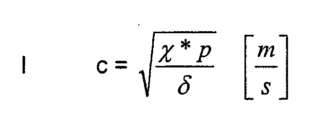
Dabei ist c die Schallgeschwindigkeit (in m/s), p ist der Luftdruck (in Pa) und δ die Dichte (in kg/m3). χ ist der materialabhängige Adiabatenexponent Cp/Cv und nimmt bei Luft in der typischen Zusammensetzung aus N2, O2 und Ar den Wert 1,4 annimmt.Here c is the speed of sound (in m / s), p is the air pressure (in Pa) and δ is the density (in kg / m 3 ). χ is the material-dependent adiabatic exponent C p / C v and assumes the value 1.4 for air in the typical composition of N 2 , O 2 and Ar.
Mit der allgemeinen Beziehung δ = p/RT, wobei R die Gaskonstante und T die
Temperatur darstellt, kann man Gleichung I umformen zu:
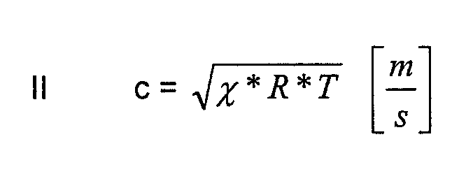
Diese Gleichung II lässt sich auflösen nach:

Die Temperatur T der Garatmosphäre ist bei Gargeräten ohnehin eine der wichtigsten Daten und wird stets gemessen. Auf sie kann daher problemlos zurückgegriffen werden.The temperature T of the cooking atmosphere is one of the most important in cooking appliances Data and is always measured. They can therefore be easily used become.
Die mittlere Gaskonstante eines Gasgemisches aus zwei Gasen, hier also aus
Luft und aus Wasserdampf, ist definiert durch:
Diese Gleichung kann man umformen zu:
Die linke Seite der Gleichung entspricht dem gesuchten Massenverhältnis Wasserdampf zu trockener Luft, das zugleich eine Angabe für die Feuchte oder Feuchtigkeit der Luft darstellt. Die Parameter Rtrockene Luft und RWasserdampf sind bekannt und RAtmosphäre erhält man aus der Messung der Schallgeschwindigkeit c und einsetzen in Gleichung III.The left side of the equation corresponds to the mass ratio of water vapor to dry air, which is also an indication of the humidity or humidity of the air. The parameters R dry air and R water vapor are known and R atmosphere is obtained from the measurement of the speed of sound c and used in Equation III.
Bei der Betrachtung wird zunächst zum leichteren Verständnis von einem konstanten Wert χ ausgegangen. Der Wert ist aber von der Gasart (Atomanzahl des Moleküls) abhängig und liegt bei Wasserdampf bei 1,33. Bei der realen Garatmosphäre mit einer Mischung aus trockener Luft und Wasserdampf wird folglich χ abhängig vom Wasserdampfgehalt zwischen 1,33 und 1,4 variieren. Dieser geringfügige Fehler in den Randwerten kann näherungsweise akzeptiert werden.When looking at it, it first becomes easier to understand one constant value χ assumed. However, the value depends on the type of gas (number of atoms of the molecule) and is 1.33 for water vapor. With the real cooking atmosphere with a mixture of dry air and water vapor χ vary between 1.33 and 1.4 depending on the water vapor content. This minor errors in the marginal values can be accepted approximately.
In einer bevorzugten Ausführungsform der Erfindung wird auch diese Randbedingung noch berücksichtigt. Dies geschieht dadurch, dass durch ein Iterationsverfahren χ genauer bestimmt wird. Dabei wird der Feuchtegehalt mit einer Annahme von χ berechnet und aufgrund des Ergebnisses eine neues χ berechnet (lineare Interpolation zwischen 1,33 und 1,4 je nach berechnetem Wasserdampfgehalt). Wenn sich der berechnete Wert von χ nicht mehr ändert (Genauigkeitsgrenzwert ), wird die Iteration beendet.In a preferred embodiment of the invention, this boundary condition also becomes still considered. This happens because of an iteration process χ is determined more precisely. The moisture content is assumed calculated from χ and calculated a new χ based on the result (linear interpolation between 1.33 and 1.4 depending on the calculated water vapor content). If the calculated value of χ no longer changes (accuracy limit ), the iteration is ended.
Ein wesentlicher Vorteil der Erfindung liegt darin, dass die Schallgeschwindigkeit relativ einfach und genau bestimmt werden kann, und zwar ohne anfällige oder komplizierte Messinstrumente, ohne Wartung und auch über eine sehr lange Benutzungszeit hinweg. A major advantage of the invention is that the speed of sound can be determined relatively easily and precisely, and without any vulnerable or complicated measuring instruments, without maintenance and also over a very long time Usage time.
Anders als bei der US-PS 5,689,062 entsteht noch ein weiterer Vorteil: Dort wird eine akustische Welle mit einer Frequenz um etwa 4 kHz eingesetzt, so dass die Feuchtebestimmung mit einer im Hörbereich des menschlichen Benutzers liegenden und damit störenden Geräuschentwicklung einhergeht. In einer bevorzugten Ausführungsform der Erfindung werden aber die Abmessungen des Rohres und die von der Einrichtung zur Erzeugung akustischer Wellen erzeugten Wellen so aufeinander abgestimmt sind, dass eine stehende Welle in einem Obermodus, insbesondere im 3. oder 4. Obermodus entsteht. Dies erlaubt es, die Frequenzen in den Bereich oberhalb von etwa 20 kHz zu verschieben, also aus dem menschlichen Hörbereich heraus.In contrast to US Pat. No. 5,689,062, there is another advantage: there is an acoustic wave with a frequency around 4 kHz is used so that the Moisture determination with a lying in the hearing range of the human user and is accompanied by disturbing noise. In a preferred one Embodiment of the invention, however, the dimensions of the tube and those generated by the acoustic wave generating device Waves are coordinated so that a standing wave in one Upper mode, especially in the 3rd or 4th upper mode. This allows the To shift frequencies in the range above about 20 kHz, so off the human listening area.
Hierzu wird beispielsweise eine Ausführungsform der Erfindung eingesetzt, bei der eine Vorrichtung zur Rückkopplung vorgesehen ist. Durch ein Hochpassfilter können jetzt alle störenden Geräusche heraus gefiltert werden, die etwa durch die Bewegung des Lüfterrades etc. entstehen und die Rückkopplung störend beeinflussen können. Durch ein Bandpassfilter, das aus den rückgekoppelten Frequenzen nur gewünschte Frequenzbereiche, insbesondere außerhalb des menschlichen Hörbereiches, zulässt, können zusätzlich ungewünschte Obertöne weg gefiltert werden. Besonders geeignet ist ein sogenanntes Mitlauffilter, auch Tracking Filter genannt, das um eine Frequenz herum im Filter aufspannt und bei variabler Mittelfrequenz "mitläuft", also den Frequenzbereich jeweils aktuell anpasst.For example, an embodiment of the invention is used for this purpose which a device for feedback is provided. Through a high pass filter can now filter out all annoying noises caused by the movement of the fan wheel etc. arise and the feedback is disruptive can influence. Through a bandpass filter that comes from the feedback Frequencies only desired frequency ranges, especially outside the human hearing range, can also undesirable overtones be filtered away. A so-called tracking filter is particularly suitable, too Called tracking filter, which spans around a frequency in the filter and at variable center frequency "follows", that is, the frequency range currently adapts.
Bei einer weiteren Ausführungsform der Erfindung weist eine Vorrichtung ein Filter auf, das aus den nachgeführten Frequenzen nur gewünschte Frequenzbereiche, insbesondere außerhalb des menschlichen Hörbereiches, zulässt. Es wird dadurch gewissermaßen ein Fenster für solche Frequenzen aufgespannt, in denen sich die Frequenzen der stehenden Welle befinden, die stehende Wellen erzeugen, die nicht mit hörbaren Schwingungen verbunden sind. Auch hier werden ungewünschte Fremdgeräusche ferngehalten.In a further embodiment of the invention, a device has Filter that only the desired frequency ranges from the tracked frequencies, especially outside the human hearing range. It will in this way, so to speak, a window for frequencies in which are the frequencies of the standing wave, the standing waves generate that are not associated with audible vibrations. Also be here unwanted extraneous noises kept away.
Vorzugsweise wird an der Position eines Schwingungsknotens der stehenden Wellen im Rohr mindestens eine Bohrung in der Rohrwandung angeordnet. Besonders bevorzugt ist es dabei zur Erzwingung der obengenannten Obermoden mindestens an der Position von zwei Schwingungsknoten der stehenden Wellen im Rohr mindestens je eine Bohrung in der Rohrwandung anzuordnen.The standing one is preferably at the position of a vibration node Shafts in the tube arranged at least one hole in the tube wall. Especially it is preferred to enforce the above-mentioned upper modes at least at the position of two vibration nodes of the standing waves arrange at least one hole in the pipe wall in the pipe.
Das erfindungsgemäße Gargerät kann die Feuchte auch bei relativ hohen Temperaturen
von 300 °C bestimmen, wie sie in Heißluftherden und Kombidämpfern
auftreten, und bei Garprozessen entsprechend bei der Regelung berücksichtigen.
Bei Tests hat sich gezeigt, dass die Feuchte auf genauer als 1 % Abweichung
bestimmt werden kann, während bei herkömmlichen Verfahren 30 % Abweichung
vorkommen können.The cooking device according to the invention can control the humidity even at relatively high temperatures
of 300 ° C, as in hot air cookers and combi steamers
occur, and take them into account accordingly in the control process.
Tests have shown that the humidity is more than 1% deviation
can be determined, while in
Das bedeutet, dass die Bestimmung der Feuchte nicht nur benutzt werden kann, tendenziell durch Zugabe oder Beendigung der Zugabe die Wasserzufuhr in die Garatmosphäre zu beeinflussen, um die Feuchte einzustellen. Es kann sogar hochgenau in den Ablauf und die Steuerung der Garprozesse eingegriffen werden, um vollautomatische Vorgänge ablaufen zu lassen, beispielsweise neu aus variablen Produkten mit unterschiedlichen Feuchtegehalten (Gemüse verschiedener Herkunft) vorgegebene Speisen optimal zu garen. This means that the moisture determination can not only be used tends to add or stop adding water to the To influence the cooking atmosphere to adjust the humidity. It can even intervene very precisely in the sequence and control of the cooking processes, to run fully automatic processes, for example, from new variable products with different moisture contents (vegetables different Origin) to optimally cook specified dishes.
Im Folgenden werden anhand der Zeichnung einige Ausführungsbeispiele der Erfindung näher erläutert. Es zeigen:
- Figur 1
- eine schematische Darstellung eines erfindungsgemäßen Gerätes;
- Figur 2
- eine schematische Darstellung einer Ausführungsform einer Einrichtung zur Bestimmung der Feuchte für ein erfindungsgemäßes Gargerät;
- Figur 3
- eine schematische Darstellung einer anderen Ausführungsform einer Einrichtung zur Bestimmung der Feuchte für ein erfindungsgemäßes Gargerät; und
- Figur 4
- eine schematische Darstellung einer Ausführungsform für eine Vergleichsmessung zur Unterstützung der Einrichtung zur Bestimmung der Feuchte.
- Figure 1
- a schematic representation of a device according to the invention;
- Figure 2
- a schematic representation of an embodiment of a device for determining the moisture for a cooking device according to the invention;
- Figure 3
- a schematic representation of another embodiment of a device for determining the moisture for a cooking device according to the invention; and
- Figure 4
- a schematic representation of an embodiment for a comparison measurement to support the device for determining the moisture.
Einen schematischen Aufbau eines Ausführungsbeispiels eines erfindungsgemäßen
Gargerätes zeigt Figur 1. Ein Gehäuse 10 enthält einen Garraum 11, der
mit einer Garatmosphäre während des Garvorganges angefüllt ist. Diese Garatmosphäre
besteht in erster Linie aus den für Luft typischen und im Verhältnis
zueinander im wesentlichen konstanten Anteilen an Stickstoff (N2), Sauerstoff
(O2) und Argon (Ar) und einem schwankenden, vom Garvorgang und dem Gargut
beeinflussten und hier besonders interessierenden Anteil an Wasserdampf
(H2O). FIG. 1 shows a schematic structure of an exemplary embodiment of a cooking device according to the invention . A
Der Garraum ist von außen durch einen Türbereich 12 zugänglich, der auch ein
Fenster aufweisen kann, das für den Benutzer eine optische Verfolgung des
Fortschrittes des Garvorganges ermöglicht.The cooking space is accessible from the outside through a
Er ist mit den für den Garvorgang und die Behandlung und Handhabung des
Gargutes erforderlichen beziehungsweise sinnvollen Elementen ausgerüstet, die
hier nur teilweise und schematisch angedeutet sind. Dazu gehören zum Beispiel
Heizkörper 20, ein Gargutträgerblech 21, ein Lüfterrad 22, eine Temperaturmesseinrichtung
23 und unter anderem auch ein Luftleitblech 25.It is used for the cooking process and the treatment and handling of the
Cooked necessary or sensible elements equipped
are only partially and schematically indicated here. These include, for
Außerdem ist auch eine Einrichtung zur Bestimmung der Feuchte beziehungsweise
eine Feuchtemesseinrichtung 30 vorgesehen.In addition, there is also a device for determining the moisture or
a
Das Ergebnis der Feuchtemesseinrichtung 30 wird an eine nachgeschaltete
Elektronik beziehungsweise Auswertungseinheit 40 übermittelt und von dort ein
Steuersignal an eine Gerätesteuerung 41 weitergegeben. Auch die Temperaturmesseinrichtung
23 ist mit der nachgeschalteten Elektronik beziehungsweise
Auswertungseinheit 40 verbunden.The result of the
In der Auswertungseinheit 40 werden die Messwerte, also die Temperatur T und
die von der Feuchtemesseinrichtung 30 festgestellten Größen verknüpft mit den
bekannten festen Größen wie beispielsweise den oben bereits erörterten Materialkonstanten.The measurement values, that is to say the temperature T and
the quantities determined by the
Das Ergebnis kann dann als Ansteuerung der Gerätesteuerung dienen. Durch Vergleich mit der Sollwertgröße wird ein entsprechender Aktor betätigt, um über einen Ist-/Soll-Vergleich nach der Sollwertvorgabe zu regeln.The result can then be used to control the device control. By In comparison with the setpoint size, a corresponding actuator is actuated to over to regulate an actual / target comparison according to the target value specification.
Es ist im Grunde nicht wesentlich für die Erfindung, wo die Elektronik 40 angeordnet
ist, ob es sich um ein einteiliges Bauteil handelt oder ob die einzelnen
Berechnungen der Schallgeschwindigkeit beziehungsweise Feuchte in unterschiedlichen
Bereichen erfolgen. Beispielsweise kann die Elektronik 40 auch ein
Teil der Sensor- oder der Geräteelektronik sein und die Berechnung bereits dort
stattfinden, ohne dass noch separate Leitungen verlegt werden müssen. It is basically not essential to the invention where the
In Figur 2 ist eine schematische Darstellung einer Ausführungsform einer Einrichtung
zur Bestimmung der Feuchte für ein erfindungsgemäßes Gargerät in
vergrößerter Wiedergabe zu erkennen. Die Einrichtung 30 weist ein Rohr 31 auf.
Das Rohr 31 ist insbesondere mit einer Einrichtung 32 zur Erzeugung akustischer
Wellen ausgerüstet. FIG. 2 shows a schematic representation of an embodiment of a device for determining the moisture for an inventive cooking device in an enlarged representation. The
Das Rohr 31 ist etwa zylindrisch aufgebaut und besitzt eine etwa zylindrische
Rohrwandung. An den beiden einander gegenüberliegenden Enden 33 und 34 ist
in dieser Ausführungsform das Rohr jeweils geschlossen. Die Einrichtung 32 zur
Erzeugung der akustischen Wellen befindet sich benachbart des einen Endes 33.
Insbesondere kann die Membran 35 b der Einrichtung 32 zum Erzeugen akustischer
Wellen vollflächig hier das Rohr 31 an diesem Ende 33 abschließen. In
diesem Falle würde die Membran 35 b das geschlossene Ende 33 im mechanischen
Sinne bilden.The
Um einen definierten Austausch mit dem zu untersuchenden Gas, also der Garraumatmosphäre
im Garraum 11, zu erzielen, sind Bohrungen 36 vorgesehen.
Diese Bohrungen 36 sind an der Position eines oder mehrerer Schwingungsknoten
der stehenden Welle angeordnet.For a defined exchange with the gas to be examined, i.e. the cooking cabinet atmosphere
To achieve in the
Diese Ausführungsform ist insbesondere für eine stark turbulente Garraumatmosphäre vorgesehen, da nur durch die Bohrungen ein Austausch mit der Garraumatmosphäre erfolgt. Die Anzahl, Größe und Lage der Bohrungen kann von der Stärke der Umgebungsturbulenz abhängig gemacht werden.This embodiment is especially for a highly turbulent cooking chamber atmosphere provided, because only through the holes an exchange with the cooking chamber atmosphere he follows. The number, size and location of the holes can vary from depending on the strength of the surrounding turbulence.
Der Durchmesser des Rohres 31 sollte geringer sein als die halbe Wellenlänge
einer stehenden Welle. Dadurch wird vermieden, dass im Rohr Querschwingungen
entstehen. Nur Longitudinalwellen in Längsrichtung können sich in diesem
Falle ausbilden. The diameter of the
Die Länge des Rohres kann exakt die Hälfte der Wellenlänge, also λ/2, betragen.
Auf diese Weise schwingt die Atmosphäre im Rohr 31 mit der Grundfrequenz.
Bei der Grundfrequenz ist die Anregung der Resonanz am einfachsten. Bevorzugt
ist allerdings eine Schwingung bei höheren Moden, etwa im dritten oder
vierten Obermodus. Dies verschiebt die Frequenz in einen Bereich oberhalb von
20 kHz, also aus dem menschlichen Hörbereich heraus. Noch höhere Moden
sind möglich, bieten aber keine weiteren Vorteile.The length of the tube can be exactly half the wavelength, ie λ / 2.
In this way, the atmosphere in
Für die Erzeugung und Aufrechterhaltung der stehenden Wellen beziehungsweise
der Resonanzschwingung bieten sich insbesondere drei unterschiedliche
Möglichkeiten an, die jeweils in der Figur 2 angedeutet sind. Es ist jeweils eine
Vorrichtung 35 vorgesehen, die die Frequenz der von der Einrichtung 32 zur Erzeugung
akustischer Wellen erzeugten Wellen so einstellt, dass akustische stehende
Wellen entstehen.For the generation and maintenance of standing waves respectively
there are three different types of resonance vibration
Possibilities, which are each indicated in Figure 2. It's one at a
In einer ersten Variante geschieht dies durch Rückkopplung. So kann ein Wechseldruckempfänger
35a, beispielsweise ein Kondensatormikrophon, in dem Rohr
angeordnet werden. Die Anordnung des Kondensatormikrophons erfolgt in einer
Position, die in der stehenden Welle einem Schwingungsbauch entspricht. Dieser
Wechseldruckempfänger 35a kann jetzt mittels Rückkopplung zur Aufrechterhaltung
der Resonanzschwingung herangezogen werden.In a first variant, this is done by feedback. So can an alternating
In einer anderen Alternative kann eine Regelung vorgesehen werden, die ständig
die Frequenz nachführt, damit die maximal mögliche Schwingungsamplitude erhalten
bleibt. Hierfür kann der Hub einer Membran 35b der Einrichtung 32 zur
Erzeugung und Aufrechterhaltung der stehenden Wellen, also des elektrostatischen
Lautsprechers, verwendet werden. Dieser Hub sollte bei dieser Nachführung
möglichst groß bleiben.In another alternative, regulation can be provided that is constant
tracks the frequency so that the maximum possible vibration amplitude is obtained
remains. For this purpose, the stroke of a
Eine dritte Alternative arbeitet mit der Messung des Speisestromes der Einrichtung
32 zur Erzeugung akustischer Wellen. Die in die Einrichtung 32 zur Erzeugung
akustischer Wellen eingespeiste Frequenz wird von einem spannungsgesteuerten
Oszillator, meist als VCO (Voltage Controlled Oscillator) bezeichnet,
erzeugt. Wenn die ansteigende Frequenz in den Resonanzbereich des Rohres
31 gelangt, verringert sich entsprechend der Speisestrom erheblich, je nach Eigendämpfung
des Systems. Bei eingetretener Resonanz hat der Speisestrom der
Einrichtung 32 zur Erzeugung akustischer Wellen den niedrigsten Wert.A third alternative works by measuring the feed current of the device
32 for generating acoustic waves. The in the device 32 for generation
Acoustic waves injected frequency is controlled by a voltage
Oscillator, mostly referred to as VCO (Voltage Controlled Oscillator),
generated. If the increasing frequency in the resonance range of the
Wenn sich durch Temperatur- und Feuchteänderungen das Schwingungssystem
verstimmt, reduziert sich dadurch die Amplitude der stehenden Welle, also der
Gassäulenschwingung in dem Rohr 31. Damit aber erhöht sich gleichzeitig die
Stromaufnahme der Einrichtung 32 zur Erzeugung akustischer Wellen.If the vibration system changes due to changes in temperature and humidity
detuned, this reduces the amplitude of the standing wave, i.e. the
Gas column vibration in the
Dieser steigende Spannungsabfall kann an einem Vorwiderstand 35c im Speisestromkreis
der Einrichtung 32 zur Erzeugung akustischer Wellen beobachtet und
benutzt werden, um den spannungsgesteuerten Oszillator nachzusteuern. Diese
Nachsteuerung erfolgt, bis der Strom beziehungsweise der Spannungsabfall an
dem Vorwiderstand 35c wiederum sein Minimum erreicht hat. Als Folge dieser
Regelung ändert sich dabei die Frequenz, die wie erörtert zur Bestimmung von
Feuchte und Temperatur herangezogen wird.This increasing voltage drop can be at a
In der Figur 3 wird eine alternative Ausführung eines Rohres 31 dargestellt.
Diese alternative Ausführung ist für eine turbulenzarme Umgebung geeignet und
kann beispielsweise in einem Bereich angeordnet werden, der mit der Garraumatmosphäre
zwar noch in Verbindung steht, gegenüber dieser jedoch strömungsmäßig
abgeschattet ist. Hier ist das Rohr 31 zwar an einem Ende 33 geschlossen,
an dem anderen Ende 34 jedoch offen. Die Länge des Rohres beträgt
in diesem Falle ein ganzzahliges Vielfaches von (2n-1) x /4. Das offene Ende 34
des Rohres kann hier unmittelbar eingesetzt werden, um den Austausch mit der
Garraumatmosphäre durch Diffusion zu ermöglichen. Es kann also auf Bohrungen
36 gegebenenfalls verzichtet werden, wenn nur die Grundschwingung verwendet
werden soll.An alternative embodiment of a
Im Übrigen sind die Merkmale dieser Ausführungsform ähnlich denen in Figur 2. Otherwise, the features of this embodiment are similar to those in FIG. 2.
Figur 4 zeigt schließlich eine weitere Möglichkeit, die in Kombination mit einem
der beiden Rohre 31 aus den Figuren 2 oder 3 eingesetzt werden kann. Figur 4
zeigt ein weiteres, im Übrigen sehr ähnlich ausgebildetes Rohr 51, das mit einer
Einrichtung 52 zur Erzeugung akustischer Wellen ausgestattet und an beiden
Enden 53, 54 geschlossen ist und keine Bohrungen zum Gasaustausch mit der
Umgebung besitzt. Dieses Rohr 51 wird mit trockener Luft gefüllt, besitzt also
konstante Feuchte. Zur Vermeidung einer Druckerhöhung im Inneren wird er
über ein Kapillarröhrchen 57 mit einem Ausgleichsbehälter 58, vorzugsweise
einem nachgiebigen Gummiball, verbunden. FIG. 4 finally shows a further possibility which can be used in combination with one of the two
Wird nun die gleiche Messung wie beispielsweise in dem Rohr 31 in Figur 2 vorgenommen,
so wird hier die Temperatur als frequenzabhängige Größe gemessen.
Sind die Temperaturen in den beiden Rohren 31, 51 identisch, so kann direkt
der Wert der Resonanzfrequenz in dem zweiten Rohr 51 in Bezug zur Resonanzfrequenz
in dem ersten Rohr 31 gesetzt und daraus auf die Feuchte geschlossen
werden.If the same measurement is now carried out as, for example, in
Eine alternative, nicht dargestellte Möglichkeit besteht darin, die Temperaturmesseinrichtung
23 einschließlich der Einrichtung 32 zur Erzeugung akustischer
Wellen vollkommen gasdicht abzuschließen, sodass keine Zerstörung der Lautsprechermembran
35b als Folge einer temperaturbedingten Druckerhöhung auftreten
kann. An alternative possibility, not shown, is the
- 1010
- Gehäusecasing
- 1111
- Garraumoven
- 1212
- Türbereichdoor area
- 2020
- Heizkörperradiator
- 2121
- GargutträgerblechGargutträgerblech
- 2222
- Lüfterradfan
- 2323
- TemperaturmesseinrichtungTemperature measuring device
- 2525
- LuftleitblechAir baffle
- 3030
- Einrichtung zur Bestimmung der Feuchte beziehungsweise FeuchtemesseinrichtungDevice for determining the moisture or moisture measuring device
- 3131
- Rohrpipe
- 3232
- Einrichtung zur Erzeugung akustischer WellenDevice for generating acoustic waves
- 3333
- Ende des RohresEnd of the tube
- 3434
- Ende des RohresEnd of the pipe
- 3535
- Vorrichtung zur Einstellung der FrequenzFrequency adjustment device
- 35a35a
- WechseldruckempfängerAlternating pressure receiver
- 35b35b
- Membranmembrane
- 35c35c
- Vorwiderstanddropping resistor
- 3636
- Bohrungendrilling
- 4040
- Auswertungseinheit beziehungsweise elektronische SchaltungEvaluation unit or electronic circuit
- 4141
- Gerätesteuerungdevice control
- 5151
- Rohrpipe
- 5252
- Einrichtung zur Erzeugung akustischer WellenDevice for generating acoustic waves
- 5353
- Ende des RohresEnd of the pipe
- 5454
- Ende des RohresEnd of the pipe
- 5757
- Kapillarröhrchencapillary
- 5858
- Ausgleichsbehältersurge tank
Claims (20)
dass eine Vorrichtung (35) vorgesehen ist, die die Frequenz der von der Einrichtung (32) zur Erzeugung akustischer Wellen erzeugten Wellen so einstellt, dass akustische stehende Wellen entstehen, und
dass die von der Vorrichtung (35) eingestellte Frequenz und die Daten der Temperaturmesseinrichtung (23) der Auswertungseinheit (40) zugeführt werden und daraus die Feuchte ermittelt wird.Cooking appliance
that a device (35) is provided which adjusts the frequency of the waves generated by the device (32) for generating acoustic waves so that acoustic standing waves arise, and
that the frequency set by the device (35) and the data from the temperature measuring device (23) are fed to the evaluation unit (40) and the moisture is determined therefrom.
dadurch gekennzeichnet, dass die Vorrichtung (35) eine Rückkopplungsvorrichtung ist, die die Einstellung der Frequenz der von der Einrichtung (32) zur Erzeugung akustischer Wellen erzeugten Wellen durch Rückkopplung vornimmt. Cooking appliance according to claim 1,
characterized in that the device (35) is a feedback device which adjusts the frequency of the waves generated by the device (32) for generating acoustic waves by feedback.
dadurch gekennzeichnet, dass die Vorrichtung (35) einen Wechseldruckempfänger aufweist, der im Rohr (31) an der Position eines Schwingungsbauches der stehenden Wellen angeordnet ist, und
dass der Wechseldruckempfänger eine Rückkopplung auf die Einrichtung zur Erzeugung der akustischen Welle (32) abgibt.Cooking appliance according to claim 2
characterized in that the device (35) has an alternating pressure receiver which is arranged in the tube (31) at the position of an antinode of the standing waves, and
that the alternating pressure receiver outputs a feedback to the device for generating the acoustic wave (32).
dadurch gekennzeichnet, dass die Vorrichtung (35) ein Hochpassfilter oder ein Bandpassfilter oder einen Mitlauffilter aufweist, das aus den rückgekoppelten Frequenzen nur gewünschte Frequenzbereiche, insbesondere außerhalb und oberhalb des menschlichen Hörbereiches, zulässt.Cooking appliance according to claim 2 or 3,
characterized in that the device (35) has a high-pass filter or a band-pass filter or a tracking filter that only allows desired frequency ranges from the feedback frequencies, in particular outside and above the human hearing range.
dadurch gekennzeichnet, dass an der Position eines Schwingungsknotens der stehenden Wellen im Rohr (31) mindestens eine Bohrung (36) in der Rohrwandung angeordnet ist.Cooking appliance according to one of the preceding claims,
characterized in that at the position of an oscillation node of the standing shafts in the tube (31) at least one bore (36) is arranged in the tube wall.
dadurch gekennzeichnet, dass mindestens an der Position von zwei Schwingungsknoten der stehenden Wellen im Rohr (31) mindestens je eine Bohrung (36) in der Rohrwandung angeordnet ist.Cooking appliance according to claim 5,
characterized in that at least at the position of two vibration nodes of the standing shafts in the tube (31) at least one bore (36) is arranged in the tube wall.
dadurch gekennzeichnet, dass die Bohrungen (36) als Schlitze ausgebildet sind. Cooking appliance according to claim 5 or 6,
characterized in that the bores (36) are designed as slots.
dadurch gekennzeichnet, dass die Bohrung (36) als das Rohr (31) in mehrere Rohrelemente trennender Schlitz ausgebildet ist.Cooking appliance according to claim 7,
characterized in that the bore (36) is designed as a slot separating the tube (31) into a plurality of tube elements.
dadurch gekennzeichnet, dass die Bohrungen einen kreisförmigen Querschnitt besitzen.Cooking appliance according to claim 5 or 6,
characterized in that the bores have a circular cross section.
dadurch gekennzeichnet, dass die Vorrichtung (35) eine Nachführvorrichtung ist, die die Einstellung der Frequenz der von der Einrichtung (32) zur Erzeugung akustischer Wellen erzeugten Wellen in Abhängigkeit von veränderlichen Messwerten vornimmt.Cooking appliance according to one of the preceding claims,
characterized in that the device (35) is a tracking device which adjusts the frequency of the waves generated by the device (32) for generating acoustic waves as a function of variable measured values.
dadurch gekennzeichnet, dass die Vorrichtung (35) ein Filter aufweist, das aus den nachgeführten Frequenzen nur gewünschte Frequenzbereiche, insbesondere außerhalb und oberhalb des menschlichen Hörbereiches, zulässt.Cooking appliance according to claim 10,
characterized in that the device (35) has a filter which only allows desired frequency ranges from the tracked frequencies, in particular outside and above the human hearing range.
dadurch gekennzeichnet, dass der Hub einer Membran (35b) der Einrichtung (32) zur Erzeugung akustischer Wellen für eine Regelung auf maximale Schwingungsamplitude herangezogen wird.Cooking appliance according to claim 10 or 11,
characterized in that the stroke of a membrane (35b) of the device (32) for generating acoustic waves is used to regulate the maximum vibration amplitude.
dadurch gekennzeichnet, dass ein spannungsgesteuerter Oszillator (voltage controlled Oscillator, VCO) vorgesehen ist, der einen Spannungsabfall an einem Widerstand im Speisestromkreis der Einrichtung für die Erzeugung der akustischen Wellen (32) zur Regelung der Frequenz verwendet. Cooking appliance according to claim 10 or 11,
characterized in that a voltage controlled oscillator (VCO) is provided which uses a voltage drop across a resistor in the supply circuit of the device for generating the acoustic waves (32) to regulate the frequency.
dadurch gekennzeichnet, dass die Abmessungen des Rohres (31) und die von der Einrichtung (32) zur Erzeugung akustischer Wellen erzeugten Wellen so aufeinander abgestimmt sind, dass eine stehende Welle in einem Obermodus, insbesondere im dritten oder vierten Obermodus entsteht.Cooking appliance according to one of the preceding claims,
characterized in that the dimensions of the tube (31) and the waves generated by the device (32) for generating acoustic waves are matched to one another in such a way that a standing wave is produced in an upper mode, in particular in the third or fourth upper mode.
dadurch gekennzeichnet, dass die Temperaturmesseinrichtung (23) ein Rohr (51) aufweist, das wie das erste Rohr (31) aufgebaut ist,
dass an beiden Enden (53, 54) geschlossen ist und keine Bohrungen (36) aufweist, und
dass zum Druckausgleich ein Kapillarröhrchen (57) besitzt, das zu einem Ausgleichsbehälter (58) führt.Cooking appliance according to one of the preceding claims,
characterized in that the temperature measuring device (23) has a tube (51) which is constructed like the first tube (31),
that is closed at both ends (53, 54) and has no bores (36), and
that has a capillary tube (57) for pressure equalization, which leads to an expansion tank (58).
dadurch gekennzeichnet, dass die Temperaturmesseinrichtung (23) ein vollkommen gasdichtes Gehäuse aufweist, das die Einrichtung (52) zur Erzeugung akustischer Wellen einschließt.Cooking appliance according to one of the preceding claims,
characterized in that the temperature measuring device (23) has a completely gas-tight housing which includes the device (52) for generating acoustic waves.
dadurch gekennzeichnet, dass der Messwert der Feuchte aus der Differenzfrequenz der akustischen Wellen in den Rohren (31, 51) ermittelt wird. Cooking appliance according to claim 15 or 16,
characterized in that the measured value of the moisture is determined from the difference frequency of the acoustic waves in the tubes (31, 51).
bei dem die Temperatur der Garatmosphäre bestimmt wird,
bei dem akustische Wellen in einem Rohr (31) erzeugt werden, und
bei dem die Schallgeschwindigkeit in dem Garraum (11) zur Bestimmung der Feuchte herangezogen wird,
dadurch gekennzeichnet, dass in dem Rohr (31) durch Resonanzanregung akustische stehende Wellen erzeugt werden,
dass die Frequenz der erzeugten akustischen Wellen so eingestellt wird, dass die Maxima der stehenden Wellen aufrecht erhalten bleiben und dass die dabei eingestellte Frequenz und die Temperatur ausgewertet und daraus die Feuchte ermittelt wird.Method for determining the humidity in the cooking atmosphere in a cooking space (11) of a cooking device,
at which the temperature of the cooking atmosphere is determined,
in which acoustic waves are generated in a tube (31), and
at which the speed of sound in the cooking space (11) is used to determine the humidity,
characterized in that acoustic standing waves are generated in the tube (31) by resonance excitation,
that the frequency of the acoustic waves generated is set in such a way that the maxima of the standing waves are maintained and that the frequency and the temperature set are evaluated and the moisture is determined therefrom.
dadurch gekennzeichnet, dass die Frequenz der erzeugten akustischen Wellen durch Rückkopplung eingestellt wird.Method according to claim 18,
characterized in that the frequency of the acoustic waves generated is adjusted by feedback.
dadurch gekennzeichnet, dass die Frequenz der erzeugten akustischen Wellen durch Nachführung eingestellt wird.Method according to claim 18,
characterized in that the frequency of the acoustic waves generated is adjusted by tracking.
Applications Claiming Priority (2)
| Application Number | Priority Date | Filing Date | Title |
|---|---|---|---|
| DE10148709 | 2001-10-06 | ||
| DE10148709 | 2001-10-06 |
Publications (3)
| Publication Number | Publication Date |
|---|---|
| EP1300079A2 true EP1300079A2 (en) | 2003-04-09 |
| EP1300079A3 EP1300079A3 (en) | 2005-04-27 |
| EP1300079B1 EP1300079B1 (en) | 2007-06-27 |
Family
ID=7701196
Family Applications (1)
| Application Number | Title | Priority Date | Filing Date |
|---|---|---|---|
| EP02022196A Expired - Lifetime EP1300079B1 (en) | 2001-10-06 | 2002-10-04 | Cooking apparatus with device for measuring moisture and method for measuring moisture in a cooking apparatus |
Country Status (3)
| Country | Link |
|---|---|
| EP (1) | EP1300079B1 (en) |
| AT (1) | ATE365456T1 (en) |
| DE (1) | DE50210369D1 (en) |
Cited By (5)
| Publication number | Priority date | Publication date | Assignee | Title |
|---|---|---|---|---|
| EP1837600A2 (en) * | 2006-03-24 | 2007-09-26 | E.G.O. ELEKTRO-GERÄTEBAU GmbH | Method for controlling or monitoring or regulating a closed electric heating device |
| EP2469174A3 (en) * | 2010-12-22 | 2014-07-02 | Miele & Cie. KG | Cooking device |
| DE102016112683A1 (en) * | 2016-07-11 | 2018-01-11 | Rational Aktiengesellschaft | Method for determining the moisture within a cooking chamber of a cooking appliance and cooking appliance |
| DE102019119071A1 (en) * | 2019-07-15 | 2021-01-07 | Miele & Cie. Kg | Method for operating a device, in particular a cooking device or drying device, and device |
| CN115145333A (en) * | 2022-07-26 | 2022-10-04 | 珠海格力电器股份有限公司 | Debugging method, debugging device, processor and debugging system of cooking equipment |
Families Citing this family (2)
| Publication number | Priority date | Publication date | Assignee | Title |
|---|---|---|---|---|
| DE102008024021B4 (en) | 2008-05-16 | 2010-02-11 | Rational Ag | Method for moisture measurement, condensing pressure chamber for this purpose and cooking appliance hereby |
| DE102016112680A1 (en) * | 2016-07-11 | 2018-01-11 | Rational Aktiengesellschaft | Cooking appliance |
Citations (7)
| Publication number | Priority date | Publication date | Assignee | Title |
|---|---|---|---|---|
| DE4141768A1 (en) | 1991-12-18 | 1993-06-24 | Miele & Cie | Cooker with visible or infrared spectroscopic moisture detector - uses wavelength=selective property of interference filter deposited on sensor of light transmitted across cooking space |
| EP0386862B1 (en) | 1989-03-09 | 1994-07-13 | LechMetall Landsberg GmbH Edelstahlerzeugnisse | Cooking apparatus |
| EP0517433B1 (en) | 1991-05-28 | 1994-09-21 | Kabushiki Kaisha Toshiba | Heating apparatus |
| DE4206845C2 (en) | 1992-03-04 | 1997-10-23 | Rational Gmbh | Device for determining the proportion of a gas component in a gas mixture and use of the device |
| US5689062A (en) | 1996-01-11 | 1997-11-18 | University Of Kentucky Research Foundation | Method of assessing tool-life in grooved tools |
| EP0701388B1 (en) | 1994-09-09 | 2000-09-20 | ELECTROLUX ZANUSSI GRANDI IMPIANTI S.p.A. | Cooking oven provided with an improved humidity measurement arrangemet |
| DE20013489U1 (en) | 2000-08-04 | 2001-01-18 | Flick, Gernot, Dipl.-Ing., 65205 Wiesbaden | Measurement of the water vapor content in the cooking space of a convection oven |
Family Cites Families (2)
| Publication number | Priority date | Publication date | Assignee | Title |
|---|---|---|---|---|
| DE906023C (en) * | 1948-10-02 | 1954-04-05 | Norbert Kurt Endell Dipl Ing | Device for measuring the moisture content of gases |
| US5689060A (en) * | 1992-03-06 | 1997-11-18 | Matsushita Electric Industrial Co., Ltd. | Humidity measuring device and a heat cooker employing the device |
-
2002
- 2002-10-04 AT AT02022196T patent/ATE365456T1/en not_active IP Right Cessation
- 2002-10-04 EP EP02022196A patent/EP1300079B1/en not_active Expired - Lifetime
- 2002-10-04 DE DE50210369T patent/DE50210369D1/en not_active Expired - Lifetime
Patent Citations (7)
| Publication number | Priority date | Publication date | Assignee | Title |
|---|---|---|---|---|
| EP0386862B1 (en) | 1989-03-09 | 1994-07-13 | LechMetall Landsberg GmbH Edelstahlerzeugnisse | Cooking apparatus |
| EP0517433B1 (en) | 1991-05-28 | 1994-09-21 | Kabushiki Kaisha Toshiba | Heating apparatus |
| DE4141768A1 (en) | 1991-12-18 | 1993-06-24 | Miele & Cie | Cooker with visible or infrared spectroscopic moisture detector - uses wavelength=selective property of interference filter deposited on sensor of light transmitted across cooking space |
| DE4206845C2 (en) | 1992-03-04 | 1997-10-23 | Rational Gmbh | Device for determining the proportion of a gas component in a gas mixture and use of the device |
| EP0701388B1 (en) | 1994-09-09 | 2000-09-20 | ELECTROLUX ZANUSSI GRANDI IMPIANTI S.p.A. | Cooking oven provided with an improved humidity measurement arrangemet |
| US5689062A (en) | 1996-01-11 | 1997-11-18 | University Of Kentucky Research Foundation | Method of assessing tool-life in grooved tools |
| DE20013489U1 (en) | 2000-08-04 | 2001-01-18 | Flick, Gernot, Dipl.-Ing., 65205 Wiesbaden | Measurement of the water vapor content in the cooking space of a convection oven |
Cited By (8)
| Publication number | Priority date | Publication date | Assignee | Title |
|---|---|---|---|---|
| EP1837600A2 (en) * | 2006-03-24 | 2007-09-26 | E.G.O. ELEKTRO-GERÄTEBAU GmbH | Method for controlling or monitoring or regulating a closed electric heating device |
| EP1837600A3 (en) * | 2006-03-24 | 2009-01-28 | E.G.O. ELEKTRO-GERÄTEBAU GmbH | Method for controlling or monitoring or regulating a closed electric heating device |
| EP2469174A3 (en) * | 2010-12-22 | 2014-07-02 | Miele & Cie. KG | Cooking device |
| DE102016112683A1 (en) * | 2016-07-11 | 2018-01-11 | Rational Aktiengesellschaft | Method for determining the moisture within a cooking chamber of a cooking appliance and cooking appliance |
| WO2018011210A1 (en) * | 2016-07-11 | 2018-01-18 | Rational Aktiengesellschaft | Method for determining the moisture content within a cooking chamber of a cooking device, and cooking device |
| US11193911B2 (en) * | 2016-07-11 | 2021-12-07 | Rational Aktiengesellschaft | Method for determining the moisture content within a cooking chamber of a cooking device, and cooking device |
| DE102019119071A1 (en) * | 2019-07-15 | 2021-01-07 | Miele & Cie. Kg | Method for operating a device, in particular a cooking device or drying device, and device |
| CN115145333A (en) * | 2022-07-26 | 2022-10-04 | 珠海格力电器股份有限公司 | Debugging method, debugging device, processor and debugging system of cooking equipment |
Also Published As
| Publication number | Publication date |
|---|---|
| ATE365456T1 (en) | 2007-07-15 |
| EP1300079B1 (en) | 2007-06-27 |
| DE50210369D1 (en) | 2007-08-09 |
| EP1300079A3 (en) | 2005-04-27 |
Similar Documents
| Publication | Publication Date | Title |
|---|---|---|
| EP2145170B1 (en) | Method for determining and/or monitoring a process variable of a medium, and corresponding apparatus | |
| DE68916356T2 (en) | Noise suppressor. | |
| DE69623611T2 (en) | Active acoustic wall | |
| DE102005025671B3 (en) | Method and device for measuring the specific gravity of a gaseous or liquid medium | |
| WO2008009522A1 (en) | Sytem for determining and/or monitoring a process quantity of a medium | |
| EP1325301A2 (en) | Device for determining and/or monitoring the viscosity of a medium in a container | |
| WO2014060175A1 (en) | Flow rate measuring device, use of said flow rate measuring device, and method for determining flow velocity | |
| CN106773705B (en) | A kind of adaptive active control method and active control system for vibration damping de-noising | |
| EP1300079B1 (en) | Cooking apparatus with device for measuring moisture and method for measuring moisture in a cooking apparatus | |
| EP0481450A1 (en) | Silencer arrangement for internal combustion engines | |
| DE102004063228A1 (en) | Measuring device and method for determining a dielectric property, in particular the humidity and / or density, of a product | |
| DE2454788A1 (en) | METHOD AND DEVICE FOR DETERMINING THE HUMIDITY OF A GASEOUS MEDIUM | |
| WO2012022663A1 (en) | Device and system for selectively detecting gas components or concentrations of gas components in a gas to be analyzed and method for operating such a device | |
| DE102004045199A1 (en) | Measuring device and method for determining temperature and / or pressure and use of the measuring device | |
| WO2012100959A1 (en) | Cylindrical device, pulse wave measurement system and method for measuring a pulse wave speed | |
| DE10143841B4 (en) | Cooking appliance with humidity measuring device | |
| DE102005035085B4 (en) | Method for adjusting the acoustic properties of a combustion chamber | |
| EP3481204B1 (en) | Method for determining the moisture content within a cooking chamber of a cooking device, and cooking device | |
| DE3618798A1 (en) | Method for measuring a physical quantity influencing the inherent oscillation of a measurement transducer | |
| EP3246479B1 (en) | Absorber unit for absorbing sound | |
| DE102016112679A1 (en) | Method and arrangement for analyzing gas properties | |
| EP3997961B1 (en) | Household microwave oven with mode variation device | |
| DE102016112678A1 (en) | Method and arrangement for analyzing gas properties | |
| EP0767896B1 (en) | Ultrasonic flowmeter with continuous zero flow calibration facility | |
| AT518284B1 (en) | Method for analyzing components of a measuring gas |
Legal Events
| Date | Code | Title | Description |
|---|---|---|---|
| PUAI | Public reference made under article 153(3) epc to a published international application that has entered the european phase |
Free format text: ORIGINAL CODE: 0009012 |
|
| AK | Designated contracting states |
Designated state(s): AT BE BG CH CY CZ DE DK EE ES FI FR GB GR IE IT LI LU MC NL PT SE SK TR Kind code of ref document: A2 Designated state(s): AT BE BG CH CY CZ DE DK EE ES FI FR GB GR IE IT LI LU MC NL PT SE SK TR |
|
| AX | Request for extension of the european patent |
Extension state: AL LT LV MK RO SI |
|
| PUAL | Search report despatched |
Free format text: ORIGINAL CODE: 0009013 |
|
| AK | Designated contracting states |
Kind code of ref document: A3 Designated state(s): AT BE BG CH CY CZ DE DK EE ES FI FR GB GR IE IT LI LU MC NL PT SE SK TR |
|
| AX | Request for extension of the european patent |
Extension state: AL LT LV MK RO SI |
|
| 17P | Request for examination filed |
Effective date: 20051021 |
|
| AKX | Designation fees paid |
Designated state(s): AT BE BG CH CY CZ DE DK EE ES FI FR GB GR IE IT LI LU MC NL PT SE SK TR |
|
| GRAP | Despatch of communication of intention to grant a patent |
Free format text: ORIGINAL CODE: EPIDOSNIGR1 |
|
| GRAS | Grant fee paid |
Free format text: ORIGINAL CODE: EPIDOSNIGR3 |
|
| GRAA | (expected) grant |
Free format text: ORIGINAL CODE: 0009210 |
|
| RAP1 | Party data changed (applicant data changed or rights of an application transferred) |
Owner name: MKN MASCHINENFABRIK KURT NEUBAUER GMBH & CO. |
|
| AK | Designated contracting states |
Kind code of ref document: B1 Designated state(s): AT BE BG CH CY CZ DE DK EE ES FI FR GB GR IE IT LI LU MC NL PT SE SK TR |
|
| REG | Reference to a national code |
Ref country code: GB Ref legal event code: FG4D Free format text: NOT ENGLISH |
|
| REG | Reference to a national code |
Ref country code: CH Ref legal event code: EP |
|
| REG | Reference to a national code |
Ref country code: IE Ref legal event code: FG4D Free format text: LANGUAGE OF EP DOCUMENT: GERMAN |
|
| REF | Corresponds to: |
Ref document number: 50210369 Country of ref document: DE Date of ref document: 20070809 Kind code of ref document: P |
|
| PG25 | Lapsed in a contracting state [announced via postgrant information from national office to epo] |
Ref country code: SE Free format text: LAPSE BECAUSE OF FAILURE TO SUBMIT A TRANSLATION OF THE DESCRIPTION OR TO PAY THE FEE WITHIN THE PRESCRIBED TIME-LIMIT Effective date: 20070927 |
|
| NLV1 | Nl: lapsed or annulled due to failure to fulfill the requirements of art. 29p and 29m of the patents act | ||
| GBV | Gb: ep patent (uk) treated as always having been void in accordance with gb section 77(7)/1977 [no translation filed] |
Effective date: 20070627 |
|
| REG | Reference to a national code |
Ref country code: IE Ref legal event code: FD4D |
|
| PG25 | Lapsed in a contracting state [announced via postgrant information from national office to epo] |
Ref country code: PT Free format text: LAPSE BECAUSE OF FAILURE TO SUBMIT A TRANSLATION OF THE DESCRIPTION OR TO PAY THE FEE WITHIN THE PRESCRIBED TIME-LIMIT Effective date: 20071127 Ref country code: ES Free format text: LAPSE BECAUSE OF FAILURE TO SUBMIT A TRANSLATION OF THE DESCRIPTION OR TO PAY THE FEE WITHIN THE PRESCRIBED TIME-LIMIT Effective date: 20071008 Ref country code: CZ Free format text: LAPSE BECAUSE OF FAILURE TO SUBMIT A TRANSLATION OF THE DESCRIPTION OR TO PAY THE FEE WITHIN THE PRESCRIBED TIME-LIMIT Effective date: 20070627 Ref country code: IE Free format text: LAPSE BECAUSE OF FAILURE TO SUBMIT A TRANSLATION OF THE DESCRIPTION OR TO PAY THE FEE WITHIN THE PRESCRIBED TIME-LIMIT Effective date: 20070627 Ref country code: NL Free format text: LAPSE BECAUSE OF FAILURE TO SUBMIT A TRANSLATION OF THE DESCRIPTION OR TO PAY THE FEE WITHIN THE PRESCRIBED TIME-LIMIT Effective date: 20070627 Ref country code: BG Free format text: LAPSE BECAUSE OF FAILURE TO SUBMIT A TRANSLATION OF THE DESCRIPTION OR TO PAY THE FEE WITHIN THE PRESCRIBED TIME-LIMIT Effective date: 20070927 |
|
| EN | Fr: translation not filed | ||
| PG25 | Lapsed in a contracting state [announced via postgrant information from national office to epo] |
Ref country code: SK Free format text: LAPSE BECAUSE OF FAILURE TO SUBMIT A TRANSLATION OF THE DESCRIPTION OR TO PAY THE FEE WITHIN THE PRESCRIBED TIME-LIMIT Effective date: 20070627 |
|
| BERE | Be: lapsed |
Owner name: MKN MASCHINENFABRIK KURT NEUBAUER G.M.B.H. & CO. Effective date: 20071031 |
|
| PG25 | Lapsed in a contracting state [announced via postgrant information from national office to epo] |
Ref country code: DK Free format text: LAPSE BECAUSE OF FAILURE TO SUBMIT A TRANSLATION OF THE DESCRIPTION OR TO PAY THE FEE WITHIN THE PRESCRIBED TIME-LIMIT Effective date: 20070627 Ref country code: GR Free format text: LAPSE BECAUSE OF FAILURE TO SUBMIT A TRANSLATION OF THE DESCRIPTION OR TO PAY THE FEE WITHIN THE PRESCRIBED TIME-LIMIT Effective date: 20070928 Ref country code: IT Free format text: LAPSE BECAUSE OF FAILURE TO SUBMIT A TRANSLATION OF THE DESCRIPTION OR TO PAY THE FEE WITHIN THE PRESCRIBED TIME-LIMIT Effective date: 20070627 |
|
| PLBE | No opposition filed within time limit |
Free format text: ORIGINAL CODE: 0009261 |
|
| STAA | Information on the status of an ep patent application or granted ep patent |
Free format text: STATUS: NO OPPOSITION FILED WITHIN TIME LIMIT |
|
| PG25 | Lapsed in a contracting state [announced via postgrant information from national office to epo] |
Ref country code: MC Free format text: LAPSE BECAUSE OF NON-PAYMENT OF DUE FEES Effective date: 20071031 Ref country code: GB Free format text: LAPSE BECAUSE OF FAILURE TO SUBMIT A TRANSLATION OF THE DESCRIPTION OR TO PAY THE FEE WITHIN THE PRESCRIBED TIME-LIMIT Effective date: 20070627 |
|
| 26N | No opposition filed |
Effective date: 20080328 |
|
| REG | Reference to a national code |
Ref country code: CH Ref legal event code: PL |
|
| PG25 | Lapsed in a contracting state [announced via postgrant information from national office to epo] |
Ref country code: LI Free format text: LAPSE BECAUSE OF NON-PAYMENT OF DUE FEES Effective date: 20071031 Ref country code: FR Free format text: LAPSE BECAUSE OF FAILURE TO SUBMIT A TRANSLATION OF THE DESCRIPTION OR TO PAY THE FEE WITHIN THE PRESCRIBED TIME-LIMIT Effective date: 20080222 Ref country code: CH Free format text: LAPSE BECAUSE OF NON-PAYMENT OF DUE FEES Effective date: 20071031 |
|
| PG25 | Lapsed in a contracting state [announced via postgrant information from national office to epo] |
Ref country code: BE Free format text: LAPSE BECAUSE OF NON-PAYMENT OF DUE FEES Effective date: 20071031 |
|
| PG25 | Lapsed in a contracting state [announced via postgrant information from national office to epo] |
Ref country code: EE Free format text: LAPSE BECAUSE OF FAILURE TO SUBMIT A TRANSLATION OF THE DESCRIPTION OR TO PAY THE FEE WITHIN THE PRESCRIBED TIME-LIMIT Effective date: 20070627 |
|
| PG25 | Lapsed in a contracting state [announced via postgrant information from national office to epo] |
Ref country code: FI Free format text: LAPSE BECAUSE OF FAILURE TO SUBMIT A TRANSLATION OF THE DESCRIPTION OR TO PAY THE FEE WITHIN THE PRESCRIBED TIME-LIMIT Effective date: 20070627 Ref country code: AT Free format text: LAPSE BECAUSE OF NON-PAYMENT OF DUE FEES Effective date: 20071004 |
|
| PG25 | Lapsed in a contracting state [announced via postgrant information from national office to epo] |
Ref country code: CY Free format text: LAPSE BECAUSE OF FAILURE TO SUBMIT A TRANSLATION OF THE DESCRIPTION OR TO PAY THE FEE WITHIN THE PRESCRIBED TIME-LIMIT Effective date: 20070627 |
|
| PG25 | Lapsed in a contracting state [announced via postgrant information from national office to epo] |
Ref country code: LU Free format text: LAPSE BECAUSE OF NON-PAYMENT OF DUE FEES Effective date: 20071004 |
|
| PG25 | Lapsed in a contracting state [announced via postgrant information from national office to epo] |
Ref country code: TR Free format text: LAPSE BECAUSE OF FAILURE TO SUBMIT A TRANSLATION OF THE DESCRIPTION OR TO PAY THE FEE WITHIN THE PRESCRIBED TIME-LIMIT Effective date: 20070627 |
|
| REG | Reference to a national code |
Ref country code: DE Ref legal event code: R082 Ref document number: 50210369 Country of ref document: DE Representative=s name: KROHER - STROBEL RECHTS- UND PATENTANWAELTE, DE Ref country code: DE Ref legal event code: R082 Ref document number: 50210369 Country of ref document: DE Representative=s name: KROHER - STROBEL RECHTS- UND PATENTANWAELTE PA, DE |
|
| PGFP | Annual fee paid to national office [announced via postgrant information from national office to epo] |
Ref country code: DE Payment date: 20191029 Year of fee payment: 18 |
|
| REG | Reference to a national code |
Ref country code: DE Ref legal event code: R119 Ref document number: 50210369 Country of ref document: DE |
|
| PG25 | Lapsed in a contracting state [announced via postgrant information from national office to epo] |
Ref country code: DE Free format text: LAPSE BECAUSE OF NON-PAYMENT OF DUE FEES Effective date: 20210501 |