EP1299208B1 - Rotary cutting tool - Google Patents
Rotary cutting tool Download PDFInfo
- Publication number
- EP1299208B1 EP1299208B1 EP01950909A EP01950909A EP1299208B1 EP 1299208 B1 EP1299208 B1 EP 1299208B1 EP 01950909 A EP01950909 A EP 01950909A EP 01950909 A EP01950909 A EP 01950909A EP 1299208 B1 EP1299208 B1 EP 1299208B1
- Authority
- EP
- European Patent Office
- Prior art keywords
- cutting
- edge portion
- tip
- edge
- interior
- Prior art date
- Legal status (The legal status is an assumption and is not a legal conclusion. Google has not performed a legal analysis and makes no representation as to the accuracy of the status listed.)
- Expired - Lifetime
Links
- 230000002093 peripheral effect Effects 0.000 claims abstract description 16
- 238000003801 milling Methods 0.000 abstract description 5
- 238000005259 measurement Methods 0.000 description 4
- 239000002826 coolant Substances 0.000 description 3
- 230000001747 exhibiting effect Effects 0.000 description 2
- XAGFODPZIPBFFR-UHFFFAOYSA-N aluminium Chemical compound [Al] XAGFODPZIPBFFR-UHFFFAOYSA-N 0.000 description 1
- 229910052782 aluminium Inorganic materials 0.000 description 1
- 238000001816 cooling Methods 0.000 description 1
- 238000005553 drilling Methods 0.000 description 1
- 230000001939 inductive effect Effects 0.000 description 1
- 238000005461 lubrication Methods 0.000 description 1
- 230000014759 maintenance of location Effects 0.000 description 1
Images


Classifications
-
- B—PERFORMING OPERATIONS; TRANSPORTING
- B23—MACHINE TOOLS; METAL-WORKING NOT OTHERWISE PROVIDED FOR
- B23C—MILLING
- B23C5/00—Milling-cutters
- B23C5/02—Milling-cutters characterised by the shape of the cutter
- B23C5/10—Shank-type cutters, i.e. with an integral shaft
-
- Y—GENERAL TAGGING OF NEW TECHNOLOGICAL DEVELOPMENTS; GENERAL TAGGING OF CROSS-SECTIONAL TECHNOLOGIES SPANNING OVER SEVERAL SECTIONS OF THE IPC; TECHNICAL SUBJECTS COVERED BY FORMER USPC CROSS-REFERENCE ART COLLECTIONS [XRACs] AND DIGESTS
- Y10—TECHNICAL SUBJECTS COVERED BY FORMER USPC
- Y10T—TECHNICAL SUBJECTS COVERED BY FORMER US CLASSIFICATION
- Y10T407/00—Cutters, for shaping
- Y10T407/19—Rotary cutting tool
- Y10T407/1946—Face or end mill
-
- Y—GENERAL TAGGING OF NEW TECHNOLOGICAL DEVELOPMENTS; GENERAL TAGGING OF CROSS-SECTIONAL TECHNOLOGIES SPANNING OVER SEVERAL SECTIONS OF THE IPC; TECHNICAL SUBJECTS COVERED BY FORMER USPC CROSS-REFERENCE ART COLLECTIONS [XRACs] AND DIGESTS
- Y10—TECHNICAL SUBJECTS COVERED BY FORMER USPC
- Y10T—TECHNICAL SUBJECTS COVERED BY FORMER US CLASSIFICATION
- Y10T407/00—Cutters, for shaping
- Y10T407/19—Rotary cutting tool
- Y10T407/1952—Having peripherally spaced teeth
- Y10T407/1956—Circumferentially staggered
- Y10T407/1958—Plural teeth spaced about a helix
-
- Y—GENERAL TAGGING OF NEW TECHNOLOGICAL DEVELOPMENTS; GENERAL TAGGING OF CROSS-SECTIONAL TECHNOLOGIES SPANNING OVER SEVERAL SECTIONS OF THE IPC; TECHNICAL SUBJECTS COVERED BY FORMER USPC CROSS-REFERENCE ART COLLECTIONS [XRACs] AND DIGESTS
- Y10—TECHNICAL SUBJECTS COVERED BY FORMER USPC
- Y10T—TECHNICAL SUBJECTS COVERED BY FORMER US CLASSIFICATION
- Y10T407/00—Cutters, for shaping
- Y10T407/19—Rotary cutting tool
- Y10T407/1952—Having peripherally spaced teeth
- Y10T407/1962—Specified tooth shape or spacing
- Y10T407/1964—Arcuate cutting edge
- Y10T407/1966—Helical tooth
Definitions
- This invention relates to rotating cutting tools.
- this invention relates to end milling tools, and most particularly to end milling tools providing improved performance for cutting while being advanced simultaneously in the direction of the tool longitudinal axis (infeed), and in a direction transverse to the tool longitudinal (translational feed), such simultaneous feed known as "ramp feed”.
- End mills are generally cylindrically shaped cutting tools comprising a body portion and shank portion, the body portion including cutting edges and the shank portion typically comprising surfaces for retention by a tool rotating device.
- the body portion comprises a tip or end comprising end cutting edges, and a cutting length comprising a plurality of flutes defining side cutting edges terminating at the tip.
- Known end mills may have straight or helical flutes, and may have two, three, four or more flutes and two, three, four, or more end cutting edges. It is known to arrange end cutting edges to lie along radii at the tip and to provide channels or gashes in the tip inter-spaced with end cutting edges and continuous between the tip circumference and the interior of the tip proximate the tip center. Further, it is known to have end cutting edges lie in planes oblique to the tool longitude and sloping at relatively shallow angles from the tool periphery toward the tip center.
- US Patent No. 2,129,417 discloses an end mill having an arcuate depression in the tip end interiorly of the end cutting edges such that the end cutting edges are of relatively short effective length and are well supported by the sloping sides of the arcuate depression.
- the end mill disclosed is described as having improved resistance to chipping of the end cutting edges.
- US Patent No. 5,049,009 discloses an end mill wherein end cutting edge portions, lying parallel to radii at the tip, slope shallowly inwardly from the tip periphery toward the shank end and intersect at the tip center.
- a primary land (referred to as a "first back-off surface") lies between each end cutting edge portion and a relief surface intersecting trailing side non-cutting surfaces.
- Another rotary cutting end mill is disclosed in EP 0 352 224 B1 . This rotary cutting tool has outside cutting edges formed along spiraling flutes on its outside periphery, as well as four end cutting edges at the tool tip.
- the specific shape of this conventional tool does not seem to guarantee optimum results during drilling and/or milling.
- US Patent No. 5,779,399 discloses an end mill wherein only one end cutting edge lies along a radius at the tip and extends from the periphery through the tip center. As shown in this reference, relief is provided in the tip end behind the end cutting edge and between the end cutting edge and a sidewall of a gash. The end cutting edge of this reference lies in a plane perpendicular to the tool longitude.
- the present invention provides a rotary cutting end mill according to claim 1, wherein end cutting edges parallel radii of the tip and lie along primary and secondary slopes from the tool periphery inwardly.
- the primary slope is relatively shallow and over a relatively short portion of the cutting edge
- the secondary slope is relatively steep and extends over the greater portion of the end cutting edge.
- the tip includes a land adjacent each end cutting edge and the primary slope provides relief in this land behind the peripheral edge of the land.
- the secondary slope promotes delivery of coolant proximate the primary slope and evacuation of chips from the cutting zone.
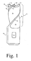
- tool 10 comprises a cutting portion 12 and a shank portion 14.
- Shank portion 14 may include surface features such as flat 16 for securing the shank portion in a device for rotating tool 10.
- Cutting portion 12 terminates in a tip end 18 comprising end cutting edges 20, 22, and 24 ( Fig. 2 ).
- Cutting portion 12 includes helical flutes 26, 28 and 30 in the circumference thereof. While three helical flutes are depicted in Fig.1 , cutting tools in accordance with the invention may include two or more flutes.
- Flutes 26, 28 and 30 define side cutting edges 32, 34, and 36, the flutes and side cutting edges shown being helical. Contours of flutes 26, 28 and 30 undercut the periphery of cutting portion 12 to produce positive cutting geometry at the cutting edges 32, 34 and 36.
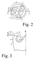
- inter-spaced with end cutting edges 20, 22, and 24 are channels, or gashes 40, 42 and 44. Gashes 40, 42 and 44 intersect the periphery of tool 10 and continue inwardly toward the center of tip 18. The bottom contour of each of gashes 40, 42 and 44 slopes from the periphery of tool 10 away from shank portion 14 toward the tip center. Typically, gashes 40, 42 and 44 undercut, respectively, end cutting edges 20, 22, and 24 to produce positive cutting geometry at the cutting edges 20, 22, and 24.
- Adjoining cutting edges 20, 22 and 24 are primary lands 46, 48, and 50. Between, respectively, lands 46, 48 and 50 and gashes 40, 42 and 44, are relief surfaces 52, 54, and 56. Relief surfaces 52, 54, and 56 are planar, sloping towards the shank end from, respectively, lands 46, 48 and 50 to non-cutting segments 58, 60, and 62 of cutting portion 12.
- FIG. 3 A side view of cutting edge 32 and end cutting edge 20 are shown in Fig. 3 .
- end cutting edge 20 intersects helical cutting edge 32 at the periphery of tip portion 18.
- end cutting edges 22 and 24 intersect helical cutting edges 36 and 34, respectively.
- each end cutting edge comprises two portions, a peripheral end edge portion, and interior edge portion, in the case of end cutting edge 20, peripheral end edge portion 70 and interior edge portion 72.
- Peripheral end edge portion 70 slopes relatively shallowly toward shank portion 14 from the tool periphery to interior edge portion 72.
- Angle 74 defining the slope of peripheral end edge portion 70, is typically 2-5 degrees, preferably greater than 2 and less than 4.5, most preferably between 3 and 4 degrees. Interior edge portion 72 slopes relatively steeply toward shank portion 14 from end edge portion 70 to intersection with gash 46. Angle 76, defining the slope of interior portion 72 is in the range of 5-25 degrees, preferably 10-20 degrees. Preferred slopes include 12-18 degrees. Land 46, adjoining cutting edge 20, also comprises two portions, peripheral end land portion 80, and interior land portion 82 ( Fig. 2 ).
- the combination of shallowly sloped end cutting edges and gashes of conventional end mills leaves substantial central portions where forces tend to push the tip center off the axis of rotation of the tool.
- the combination of gashes and relatively steep sloping interior end edge portions of end milling tools according to the invention provides relief proximate the center of tip 18, reducing forces tending to drive the tip center off the axis of rotation of the tool. Due to the reduction in forces, the feed rate can be increased, allowing faster cutting. Further, the steep sloping interior end edge portions allow heat to escape from the cutting edge workpiece interface and allow coolant to contact this interface for lubrication and cooling.
- Cutting tests were made comparing performance of tools in accordance with the invention and like tools wherein the end cutting edges were singly sloped from the tool periphery to their interior terminations.
- the tools tested were three fluted, carbide end mills, 0.50 inch cutting diameter, with three end cutting edges.
- Cutting tests were performed on a workpiece of 6061T85 aluminum, the tool being rotated at 3500 rpm, and driven along ramps of selected angles at a depth of cut of 0.50 inches, and a width of cut of 0.25 inches. Feedrates were varied to vary the feed per tooth of the tip cutting edges from 0.003 inches to 0.01 inches (workpieces were pre-machined with the appropriate ramp angle to produce constant depth of cut).
Landscapes
- Engineering & Computer Science (AREA)
- Mechanical Engineering (AREA)
- Milling Processes (AREA)
- Drilling Tools (AREA)
Abstract
Description
- This invention relates to rotating cutting tools. In particular, this invention relates to end milling tools, and most particularly to end milling tools providing improved performance for cutting while being advanced simultaneously in the direction of the tool longitudinal axis (infeed), and in a direction transverse to the tool longitudinal (translational feed), such simultaneous feed known as "ramp feed".
- End mills are generally cylindrically shaped cutting tools comprising a body portion and shank portion, the body portion including cutting edges and the shank portion typically comprising surfaces for retention by a tool rotating device. Typically, the body portion comprises a tip or end comprising end cutting edges, and a cutting length comprising a plurality of flutes defining side cutting edges terminating at the tip. Known end mills may have straight or helical flutes, and may have two, three, four or more flutes and two, three, four, or more end cutting edges. It is known to arrange end cutting edges to lie along radii at the tip and to provide channels or gashes in the tip inter-spaced with end cutting edges and continuous between the tip circumference and the interior of the tip proximate the tip center. Further, it is known to have end cutting edges lie in planes oblique to the tool longitude and sloping at relatively shallow angles from the tool periphery toward the tip center.
-
US Patent No. 2,129,417 discloses an end mill having an arcuate depression in the tip end interiorly of the end cutting edges such that the end cutting edges are of relatively short effective length and are well supported by the sloping sides of the arcuate depression. The end mill disclosed is described as having improved resistance to chipping of the end cutting edges. -
US Patent No. 5,049,009 discloses an end mill wherein end cutting edge portions, lying parallel to radii at the tip, slope shallowly inwardly from the tip periphery toward the shank end and intersect at the tip center. A primary land (referred to as a "first back-off surface") lies between each end cutting edge portion and a relief surface intersecting trailing side non-cutting surfaces. Another rotary cutting end mill is disclosed inEP 0 352 224 B1 -
US Patent No. 5,779,399 discloses an end mill wherein only one end cutting edge lies along a radius at the tip and extends from the periphery through the tip center. As shown in this reference, relief is provided in the tip end behind the end cutting edge and between the end cutting edge and a sidewall of a gash. The end cutting edge of this reference lies in a plane perpendicular to the tool longitude. - Known end mills tend to chatter during ramp feeding at nominal feed rates because of the relatively high forces acting on the trailing side of the tip end. To avoid tool chatter, it is conventional to reduce feed rates below nominal values during ramp feeding. Consequently, there is a need for an end mill providing improved cutting performance during ramp feeding, particularly exhibiting reduced chatter inducing forces and allowing feed at nominal feed rates.
- It is an object of the present invention to provide an end mill exhibiting free cutting in ramp feeding whereby forces are reduced.
- It is a further object of the present invention to provide an end mill providing improved delivery of coolant to the end cutting edge.
- Further objects and advantages of the invention shall be made apparent from the accompanying drawings and the following description thereof.
- In accordance with the aforesaid objects, the present invention provides a rotary cutting end mill according to
claim 1, wherein end cutting edges parallel radii of the tip and lie along primary and secondary slopes from the tool periphery inwardly. The primary slope is relatively shallow and over a relatively short portion of the cutting edge, the secondary slope is relatively steep and extends over the greater portion of the end cutting edge. The tip includes a land adjacent each end cutting edge and the primary slope provides relief in this land behind the peripheral edge of the land. The secondary slope promotes delivery of coolant proximate the primary slope and evacuation of chips from the cutting zone. -
-
Fig. 1 is a side view of an end mill in accordance with the invention. -
Fig. 2 is a top view of the tip end of the end mill ofFig. 1 . -
Fig. 3 is a partial section of a cutting portion of the cutting tool taken along lines A-A ofFig. 2 . -
Figs. 4 - 7 are graphs of measured forces from cutting tests of tools in accordance with the invention and tools in accordance with the prior art. - Referring to
Fig. 1 , tool 10 comprises acutting portion 12 and ashank portion 14. Shankportion 14 may include surface features such as flat 16 for securing the shank portion in a device for rotating tool 10.Cutting portion 12 terminates in atip end 18 comprisingend cutting edges Fig. 2 ).Cutting portion 12 includeshelical flutes Fig.1 , cutting tools in accordance with the invention may include two or more flutes.Flutes side cutting edges flutes portion 12 to produce positive cutting geometry at thecutting edges - Referring to
Fig. 2 , inter-spaced withend cutting edges gashes Gashes tip 18. The bottom contour of each ofgashes shank portion 14 toward the tip center. Typically,gashes end cutting edges cutting edges cutting edges primary lands lands gashes relief surfaces Relief surfaces lands non-cutting segments cutting portion 12. - A side view of
cutting edge 32 andend cutting edge 20 are shown inFig. 3 . As seen inFig. 3 ,end cutting edge 20 intersectshelical cutting edge 32 at the periphery oftip portion 18. Likewise,end cutting edges helical cutting edges Fig. 3 , each end cutting edge comprises two portions, a peripheral end edge portion, and interior edge portion, in the case ofend cutting edge 20, peripheralend edge portion 70 andinterior edge portion 72. Peripheralend edge portion 70 slopes relatively shallowly towardshank portion 14 from the tool periphery tointerior edge portion 72. Angle 74, defining the slope of peripheralend edge portion 70, is typically 2-5 degrees, preferably greater than 2 and less than 4.5, most preferably between 3 and 4 degrees.Interior edge portion 72 slopes relatively steeply towardshank portion 14 fromend edge portion 70 to intersection withgash 46. Angle 76, defining the slope ofinterior portion 72 is in the range of 5-25 degrees, preferably 10-20 degrees. Preferred slopes include 12-18 degrees.Land 46, adjoiningcutting edge 20, also comprises two portions, peripheralend land portion 80, and interior land portion 82 (Fig. 2 ). - The combination of shallowly sloped end cutting edges and gashes of conventional end mills leaves substantial central portions where forces tend to push the tip center off the axis of rotation of the tool. The combination of gashes and relatively steep sloping interior end edge portions of end milling tools according to the invention provides relief proximate the center of
tip 18, reducing forces tending to drive the tip center off the axis of rotation of the tool. Due to the reduction in forces, the feed rate can be increased, allowing faster cutting. Further, the steep sloping interior end edge portions allow heat to escape from the cutting edge workpiece interface and allow coolant to contact this interface for lubrication and cooling. - Cutting tests were made comparing performance of tools in accordance with the invention and like tools wherein the end cutting edges were singly sloped from the tool periphery to their interior terminations. The tools tested were three fluted, carbide end mills, 0.50 inch cutting diameter, with three end cutting edges. Cutting tests were performed on a workpiece of 6061T85 aluminum, the tool being rotated at 3500 rpm, and driven along ramps of selected angles at a depth of cut of 0.50 inches, and a width of cut of 0.25 inches. Feedrates were varied to vary the feed per tooth of the tip cutting edges from 0.003 inches to 0.01 inches (workpieces were pre-machined with the appropriate ramp angle to produce constant depth of cut). During the cutting tests, forces along three orthogonal axes were measured using a three axis strain gauge dynamometer and the measured forces plotted to produce the test results illustrated in the graphs of
Figs. 4 - 7 (negative values reflect the direction of the measured force along the identified axis). Cutting associated with measurements appearing inFig. 4 was performed at a ramp angle of zero degrees. Cutting associated with measurements appearing inFig. 5 was performed at a ramp angle of fifteen degrees. Cutting associated with measurements appearing inFig. 6 was performed at a ramp angle of 30 degrees. Cutting associated with measurements appearing inFig. 7 was performed at a ramp angle of 45 degrees. - Referring to
Figs. 4 - 7 , it is seen that tools in accordance with the invention exhibited reduced force in all directions as compared to forces associated with cutters in accordance with the prior art, i.e., lacking the relatively steeply inclined interior portion of the end cutting edges. With increased ramp angle, the reduction of forces exhibited by cutters according to the invention increased. - While the invention has been illustrated with reference to a preferred embodiment, and the preferred embodiment has been described in considerable detail, it is not the intention of the inventors to limit the invention to such details. Rather, it is intended that the invention be defined by the appended claims and all equivalents thereof.
Claims (6)
- A rotary cutting end mill having a shank portion (14) and a cutting portion (12), the cutting portion (12) comprising a plurality of side cutting edges (32,34,36) on the circumference thereof, each side cutting edge (32,34,36) defined by a flute (26,28,30) formed in the circumference, and the cutting portion (12) terminating in a tip comprising a plurality of end cutting edges (20,22,24), each end cutting edge (20,22,24) extending radially outward from the axis of rotation of the end mill to the periphery of the tip and thereat intersecting a side cutting edge (32,34,36) and comprising a peripheral end edge portion (70) at the intersection with a side cutting edge (32,34,36) and an interior edge portion (72) interiorly from the peripheral end edge portion (70), the peripheral end edge portion (70) sloping shallowly from the tip periphery towards the shank portion (14), and the interior edge portion (72) sloping relatively steeply from the peripheral end edge portion (70) towards the shank portion (14), the pheripheral end edge portion (70) and the interior edge portion (72) of each end cutting edge (20,22,24) extending along a radius when viewed in the direction of the axis of rotation of the end mill.
- The rotary cutting end mill of claim 1 wherein the tip further comprises a plurality of primary lands (46,48,50), each primary land (46,48,50) adjoining a respective end cutting edge (20,22,24) and comprising a peripheral end land portion (80) adjoining the peripheral end edge portion (70) and an interior land portion (82) adjoining the interior edge portion (72).
- The rotary cutting end mill of claim 2 wherein the tip further comprises a plurality of relief surfaces (52,54,56), each relief surface (52,54,56) adjoining a respective primary land (46,48,50) and sloping therefrom towards the shank portion (14) to intersection with a non-cutting segment of the cutting portion (12) circumference.
- The rotary cutting end mill of claim 3 wherein the tip further comprises a plurality of channels (40,42,44), each channel (40,42,44) continuous from a non-cutting segment of the cutting portion (12) to a terminus proximate the tip center and adjoining a respective relief surface (52,54,56) and intersecting a respective interior edge portion (72).
- The rotary cutting end mill of claim 1 wherein the peripheral end edge portion (70) slopes at an angle in the range of 2-5 degrees.
- The rotary cutting end mill of claim 5 wherein the interior edge portion (72) slopes at an angle in the range of 5-25 degrees.
Applications Claiming Priority (3)
| Application Number | Priority Date | Filing Date | Title |
|---|---|---|---|
| US09/611,740 US6435780B1 (en) | 2000-07-07 | 2000-07-07 | Rotary cutting tool |
| US611740 | 2000-07-07 | ||
| PCT/US2001/021331 WO2002004159A1 (en) | 2000-07-07 | 2001-07-05 | Rotary cutting tool |
Publications (2)
| Publication Number | Publication Date |
|---|---|
| EP1299208A1 EP1299208A1 (en) | 2003-04-09 |
| EP1299208B1 true EP1299208B1 (en) | 2009-09-09 |
Family
ID=24450238
Family Applications (1)
| Application Number | Title | Priority Date | Filing Date |
|---|---|---|---|
| EP01950909A Expired - Lifetime EP1299208B1 (en) | 2000-07-07 | 2001-07-05 | Rotary cutting tool |
Country Status (8)
| Country | Link |
|---|---|
| US (1) | US6435780B1 (en) |
| EP (1) | EP1299208B1 (en) |
| KR (1) | KR100485676B1 (en) |
| AT (1) | ATE442220T1 (en) |
| CA (1) | CA2384124C (en) |
| DE (1) | DE60139869D1 (en) |
| ES (1) | ES2331408T3 (en) |
| WO (1) | WO2002004159A1 (en) |
Cited By (1)
| Publication number | Priority date | Publication date | Assignee | Title |
|---|---|---|---|---|
| EP3150313A1 (en) | 2015-09-30 | 2017-04-05 | Fraisa SA | Solid milling tool for machining rotating materials |
Families Citing this family (24)
| Publication number | Priority date | Publication date | Assignee | Title |
|---|---|---|---|---|
| DE10104580B4 (en) * | 2001-02-01 | 2005-03-03 | Gebr. Brasseler Gmbh & Co. Kg | milling tool |
| JP4313579B2 (en) * | 2003-01-22 | 2009-08-12 | オーエスジー株式会社 | Square end mill |
| US20050053439A1 (en) * | 2003-09-09 | 2005-03-10 | Yuhong Wang | Two-flute twist drill |
| CN100479958C (en) * | 2004-03-12 | 2009-04-22 | 山特维克知识产权股份有限公司 | Cutting tool and method for cutting material |
| EP1725358B1 (en) * | 2004-03-12 | 2019-07-10 | Sandvik Intellectual Property AB | Cutting tool and method for cutting material |
| US7731738B2 (en) * | 2005-12-09 | 2010-06-08 | Orthopro, Llc | Cannulated screw |
| US8414228B2 (en) | 2006-01-04 | 2013-04-09 | Sgs Tool Company | Rotary cutting tool |
| JP5287405B2 (en) | 2009-03-23 | 2013-09-11 | 三菱マテリアル株式会社 | End mill |
| US9227253B1 (en) * | 2009-03-30 | 2016-01-05 | Steven M. Swift | Rotary cutter for machining materials |
| US8827600B2 (en) * | 2009-05-25 | 2014-09-09 | Hitachi Tool Engineering, Ltd. | Carbide end mill and cutting method using the end mill |
| CN102615324A (en) * | 2011-01-28 | 2012-08-01 | 鸿富锦精密工业(深圳)有限公司 | Milling cutter |
| CN103764326B (en) * | 2011-06-17 | 2015-12-16 | 日立工具股份有限公司 | Multiflute end mill |
| US9232952B2 (en) | 2012-04-16 | 2016-01-12 | Medtronic Ps Medical, Inc. | Surgical bur with non-paired flutes |
| US20140356081A1 (en) * | 2013-05-30 | 2014-12-04 | Kennametal Inc. | End mill with high ramp angle capability |
| US9883873B2 (en) | 2013-07-17 | 2018-02-06 | Medtronic Ps Medical, Inc. | Surgical burs with geometries having non-drifting and soft tissue protective characteristics |
| DE102014103103A1 (en) * | 2014-03-07 | 2015-09-10 | Gühring KG | End mills |
| US10335166B2 (en) | 2014-04-16 | 2019-07-02 | Medtronics Ps Medical, Inc. | Surgical burs with decoupled rake surfaces and corresponding axial and radial rake angles |
| US10058934B2 (en) | 2014-06-18 | 2018-08-28 | Kyocera Sgs Precision Tools, Inc. | Rotary cutting tool with honed edges |
| WO2016152611A1 (en) * | 2015-03-20 | 2016-09-29 | 三菱日立ツール株式会社 | Square end mill |
| US9955981B2 (en) | 2015-03-31 | 2018-05-01 | Medtronic Xomed, Inc | Surgical burs with localized auxiliary flutes |
| US10265082B2 (en) | 2015-08-31 | 2019-04-23 | Medtronic Ps Medical, Inc. | Surgical burs |
| MX2019004697A (en) | 2016-10-21 | 2019-06-17 | Kyocera Sgs Prec Tools Inc | Drills and methods of using the same. |
| MX2021001579A (en) * | 2018-08-09 | 2021-07-15 | Kyocera Sgs Prec Tools Inc | Variable radius gash. |
| DE102019114703A1 (en) * | 2019-05-31 | 2020-12-03 | Hofmann & Vratny Ohg | Milling tool with centering effect |
Family Cites Families (19)
| Publication number | Priority date | Publication date | Assignee | Title |
|---|---|---|---|---|
| US2129417A (en) | 1936-03-14 | 1938-09-06 | Weldon Tool Co | End mill |
| US2129418A (en) * | 1936-09-21 | 1938-09-06 | Weldon Tool Co | Milling tool |
| US2377329A (en) * | 1944-04-01 | 1945-06-05 | Weldon Tool Co | End mill |
| FR1125464A (en) | 1954-04-27 | 1956-10-31 | Illinois Tool Works | End mill |
| US4529341A (en) | 1982-09-29 | 1985-07-16 | Hughes Helicopters, Inc. | Drill bit for Kevlar laminates |
| US4810136A (en) * | 1983-11-09 | 1989-03-07 | The Boeing Company | Milling cutter for composite laminates |
| DE3344620A1 (en) | 1983-12-09 | 1985-06-20 | Hartmetallwerkzeugfabrik Andreas Maier GmbH + Co KG, 7959 Schwendi | MULTI-CUTTING DRILL |
| DE3706282A1 (en) | 1986-02-28 | 1987-09-03 | Izumo Sangyo Kk | CIRCULAR CUTTING TOOL |
| US5141369A (en) | 1988-07-18 | 1992-08-25 | Palace Hilard F | Cutting tool for plastic materials |
| US5094573A (en) | 1988-07-21 | 1992-03-10 | Hougen Everett D | Multidirectional cutting tool |
| US5190420A (en) | 1989-06-20 | 1993-03-02 | Hitachi Tool Kabushiki Kaisha | Solid end mill for finishing the face or side of hard work |
| US5049009A (en) * | 1990-08-21 | 1991-09-17 | The Weldon Tool Company | Improved cutting tool |
| US5322394A (en) | 1992-03-09 | 1994-06-21 | Hitachi Tool Engineering, Ltd. | Highly stiff end mill |
| US5273380A (en) * | 1992-07-31 | 1993-12-28 | Musacchia James E | Drill bit point |
| US5236291A (en) * | 1992-08-31 | 1993-08-17 | General Motors Corporation | Multi-tooth drill with improved chisel edge |
| US5855458A (en) | 1993-03-09 | 1999-01-05 | Hydra Tools International Plc | Rotary cutter |
| US5609447A (en) | 1993-11-15 | 1997-03-11 | Rogers Tool Works, Inc. | Surface decarburization of a drill bit |
| US5779399A (en) | 1996-03-05 | 1998-07-14 | Mcdonnell Douglas | Rotary cutting apparatus |
| US6618355B1 (en) * | 1999-05-07 | 2003-09-09 | Carriercomm, Inc. | Service tariffing based on usage indicators in a radio based network |
-
2000
- 2000-07-07 US US09/611,740 patent/US6435780B1/en not_active Expired - Lifetime
-
2001
- 2001-07-05 WO PCT/US2001/021331 patent/WO2002004159A1/en not_active Ceased
- 2001-07-05 EP EP01950909A patent/EP1299208B1/en not_active Expired - Lifetime
- 2001-07-05 ES ES01950909T patent/ES2331408T3/en not_active Expired - Lifetime
- 2001-07-05 KR KR10-2002-7002939A patent/KR100485676B1/en not_active Expired - Lifetime
- 2001-07-05 AT AT01950909T patent/ATE442220T1/en not_active IP Right Cessation
- 2001-07-05 DE DE60139869T patent/DE60139869D1/en not_active Expired - Lifetime
- 2001-07-05 CA CA002384124A patent/CA2384124C/en not_active Expired - Lifetime
Cited By (1)
| Publication number | Priority date | Publication date | Assignee | Title |
|---|---|---|---|---|
| EP3150313A1 (en) | 2015-09-30 | 2017-04-05 | Fraisa SA | Solid milling tool for machining rotating materials |
Also Published As
| Publication number | Publication date |
|---|---|
| CA2384124C (en) | 2007-03-06 |
| CA2384124A1 (en) | 2002-01-17 |
| EP1299208A1 (en) | 2003-04-09 |
| ES2331408T3 (en) | 2010-01-04 |
| DE60139869D1 (en) | 2009-10-22 |
| KR20020043216A (en) | 2002-06-08 |
| ATE442220T1 (en) | 2009-09-15 |
| KR100485676B1 (en) | 2005-04-27 |
| WO2002004159A1 (en) | 2002-01-17 |
| US6435780B1 (en) | 2002-08-20 |
Similar Documents
| Publication | Publication Date | Title |
|---|---|---|
| US6435780B1 (en) | Rotary cutting tool | |
| EP1791671B1 (en) | A milling tool, a cutting insert for milling tool as well as a solid milling tool | |
| US6220795B1 (en) | Spotting drill and milling cutter | |
| US4844643A (en) | Boring and milling tool and indexable cutter bit insert for use therein | |
| US9168601B2 (en) | Multi-flute reamer and cutting insert therefor | |
| US4618296A (en) | Cutting tool and insert therefor | |
| EP0094921A1 (en) | Cutting insert | |
| JP2008062382A (en) | Sintered cutting insert with center hole for tightening screw | |
| US20100284753A1 (en) | Cutting Insert for High Feed Face Milling | |
| EP0620071A1 (en) | Improved cutting tool and insert therefor | |
| JP2005535461A (en) | Spiral insert and cutter body | |
| US4470733A (en) | Multiple function cutting tool | |
| US5597269A (en) | Cutting tool for honeycomb core | |
| US20050271482A1 (en) | Ballnose end mill | |
| JPS625726B2 (en) | ||
| US20220001464A1 (en) | Method of producing drill | |
| JP4326301B2 (en) | End mill | |
| JP2002018629A (en) | Cutting tools | |
| JP3270999B2 (en) | Indexable end mill | |
| EP4349515A1 (en) | End mill | |
| JP3710360B2 (en) | Spiral tap and manufacturing method thereof | |
| JP2557189Y2 (en) | End mill | |
| US20010031181A1 (en) | Indexable drill and cutting inserts therefor | |
| JP4142892B2 (en) | Blade-replaceable rotary tool | |
| CN217223765U (en) | Tool bit and tool comprising same |
Legal Events
| Date | Code | Title | Description |
|---|---|---|---|
| PUAI | Public reference made under article 153(3) epc to a published international application that has entered the european phase |
Free format text: ORIGINAL CODE: 0009012 |
|
| 17P | Request for examination filed |
Effective date: 20020405 |
|
| AK | Designated contracting states |
Kind code of ref document: A1 Designated state(s): AT BE CH CY DE DK ES FI FR GB GR IE IT LI LU MC NL PT SE TR |
|
| AX | Request for extension of the european patent |
Extension state: AL LT LV MK RO SI |
|
| RAP1 | Party data changed (applicant data changed or rights of an application transferred) |
Owner name: BERKSHIRE PRECISION TOOL, LLC |
|
| 17Q | First examination report despatched |
Effective date: 20070123 |
|
| GRAP | Despatch of communication of intention to grant a patent |
Free format text: ORIGINAL CODE: EPIDOSNIGR1 |
|
| GRAS | Grant fee paid |
Free format text: ORIGINAL CODE: EPIDOSNIGR3 |
|
| GRAA | (expected) grant |
Free format text: ORIGINAL CODE: 0009210 |
|
| AK | Designated contracting states |
Kind code of ref document: B1 Designated state(s): AT BE CH CY DE DK ES FI FR GB GR IE IT LI LU MC NL PT SE TR |
|
| REG | Reference to a national code |
Ref country code: GB Ref legal event code: FG4D |
|
| REG | Reference to a national code |
Ref country code: CH Ref legal event code: EP |
|
| REG | Reference to a national code |
Ref country code: IE Ref legal event code: FG4D |
|
| REF | Corresponds to: |
Ref document number: 60139869 Country of ref document: DE Date of ref document: 20091022 Kind code of ref document: P |
|
| REG | Reference to a national code |
Ref country code: SE Ref legal event code: TRGR |
|
| REG | Reference to a national code |
Ref country code: ES Ref legal event code: FG2A Ref document number: 2331408 Country of ref document: ES Kind code of ref document: T3 |
|
| PG25 | Lapsed in a contracting state [announced via postgrant information from national office to epo] |
Ref country code: FI Free format text: LAPSE BECAUSE OF FAILURE TO SUBMIT A TRANSLATION OF THE DESCRIPTION OR TO PAY THE FEE WITHIN THE PRESCRIBED TIME-LIMIT Effective date: 20090909 |
|
| NLV1 | Nl: lapsed or annulled due to failure to fulfill the requirements of art. 29p and 29m of the patents act | ||
| PG25 | Lapsed in a contracting state [announced via postgrant information from national office to epo] |
Ref country code: NL Free format text: LAPSE BECAUSE OF FAILURE TO SUBMIT A TRANSLATION OF THE DESCRIPTION OR TO PAY THE FEE WITHIN THE PRESCRIBED TIME-LIMIT Effective date: 20090909 |
|
| PG25 | Lapsed in a contracting state [announced via postgrant information from national office to epo] |
Ref country code: CY Free format text: LAPSE BECAUSE OF FAILURE TO SUBMIT A TRANSLATION OF THE DESCRIPTION OR TO PAY THE FEE WITHIN THE PRESCRIBED TIME-LIMIT Effective date: 20090909 |
|
| PG25 | Lapsed in a contracting state [announced via postgrant information from national office to epo] |
Ref country code: PT Free format text: LAPSE BECAUSE OF FAILURE TO SUBMIT A TRANSLATION OF THE DESCRIPTION OR TO PAY THE FEE WITHIN THE PRESCRIBED TIME-LIMIT Effective date: 20100111 |
|
| PG25 | Lapsed in a contracting state [announced via postgrant information from national office to epo] |
Ref country code: AT Free format text: LAPSE BECAUSE OF FAILURE TO SUBMIT A TRANSLATION OF THE DESCRIPTION OR TO PAY THE FEE WITHIN THE PRESCRIBED TIME-LIMIT Effective date: 20090909 Ref country code: BE Free format text: LAPSE BECAUSE OF FAILURE TO SUBMIT A TRANSLATION OF THE DESCRIPTION OR TO PAY THE FEE WITHIN THE PRESCRIBED TIME-LIMIT Effective date: 20090909 |
|
| PLBE | No opposition filed within time limit |
Free format text: ORIGINAL CODE: 0009261 |
|
| STAA | Information on the status of an ep patent application or granted ep patent |
Free format text: STATUS: NO OPPOSITION FILED WITHIN TIME LIMIT |
|
| PG25 | Lapsed in a contracting state [announced via postgrant information from national office to epo] |
Ref country code: DK Free format text: LAPSE BECAUSE OF FAILURE TO SUBMIT A TRANSLATION OF THE DESCRIPTION OR TO PAY THE FEE WITHIN THE PRESCRIBED TIME-LIMIT Effective date: 20090909 |
|
| 26N | No opposition filed |
Effective date: 20100610 |
|
| PG25 | Lapsed in a contracting state [announced via postgrant information from national office to epo] |
Ref country code: GR Free format text: LAPSE BECAUSE OF FAILURE TO SUBMIT A TRANSLATION OF THE DESCRIPTION OR TO PAY THE FEE WITHIN THE PRESCRIBED TIME-LIMIT Effective date: 20091210 |
|
| PG25 | Lapsed in a contracting state [announced via postgrant information from national office to epo] |
Ref country code: MC Free format text: LAPSE BECAUSE OF NON-PAYMENT OF DUE FEES Effective date: 20100731 |
|
| REG | Reference to a national code |
Ref country code: CH Ref legal event code: PL |
|
| PG25 | Lapsed in a contracting state [announced via postgrant information from national office to epo] |
Ref country code: CH Free format text: LAPSE BECAUSE OF NON-PAYMENT OF DUE FEES Effective date: 20100731 Ref country code: LI Free format text: LAPSE BECAUSE OF NON-PAYMENT OF DUE FEES Effective date: 20100731 |
|
| PG25 | Lapsed in a contracting state [announced via postgrant information from national office to epo] |
Ref country code: IE Free format text: LAPSE BECAUSE OF NON-PAYMENT OF DUE FEES Effective date: 20100705 |
|
| PG25 | Lapsed in a contracting state [announced via postgrant information from national office to epo] |
Ref country code: LU Free format text: LAPSE BECAUSE OF NON-PAYMENT OF DUE FEES Effective date: 20100705 |
|
| PG25 | Lapsed in a contracting state [announced via postgrant information from national office to epo] |
Ref country code: TR Free format text: LAPSE BECAUSE OF FAILURE TO SUBMIT A TRANSLATION OF THE DESCRIPTION OR TO PAY THE FEE WITHIN THE PRESCRIBED TIME-LIMIT Effective date: 20090909 |
|
| REG | Reference to a national code |
Ref country code: FR Ref legal event code: PLFP Year of fee payment: 16 |
|
| REG | Reference to a national code |
Ref country code: FR Ref legal event code: PLFP Year of fee payment: 17 |
|
| REG | Reference to a national code |
Ref country code: FR Ref legal event code: PLFP Year of fee payment: 18 |
|
| PGFP | Annual fee paid to national office [announced via postgrant information from national office to epo] |
Ref country code: DE Payment date: 20200721 Year of fee payment: 20 Ref country code: GB Payment date: 20200727 Year of fee payment: 20 Ref country code: FR Payment date: 20200721 Year of fee payment: 20 Ref country code: ES Payment date: 20200922 Year of fee payment: 20 |
|
| PGFP | Annual fee paid to national office [announced via postgrant information from national office to epo] |
Ref country code: SE Payment date: 20200727 Year of fee payment: 20 Ref country code: IT Payment date: 20200724 Year of fee payment: 20 |
|
| REG | Reference to a national code |
Ref country code: DE Ref legal event code: R071 Ref document number: 60139869 Country of ref document: DE |
|
| REG | Reference to a national code |
Ref country code: GB Ref legal event code: PE20 Expiry date: 20210704 |
|
| REG | Reference to a national code |
Ref country code: SE Ref legal event code: EUG |
|
| PG25 | Lapsed in a contracting state [announced via postgrant information from national office to epo] |
Ref country code: GB Free format text: LAPSE BECAUSE OF EXPIRATION OF PROTECTION Effective date: 20210704 |
|
| REG | Reference to a national code |
Ref country code: ES Ref legal event code: FD2A Effective date: 20211230 |
|
| PG25 | Lapsed in a contracting state [announced via postgrant information from national office to epo] |
Ref country code: ES Free format text: LAPSE BECAUSE OF EXPIRATION OF PROTECTION Effective date: 20210706 |