EP1299201B1 - Sliding closure for casting molten metal - Google Patents
Sliding closure for casting molten metal Download PDFInfo
- Publication number
- EP1299201B1 EP1299201B1 EP01957934A EP01957934A EP1299201B1 EP 1299201 B1 EP1299201 B1 EP 1299201B1 EP 01957934 A EP01957934 A EP 01957934A EP 01957934 A EP01957934 A EP 01957934A EP 1299201 B1 EP1299201 B1 EP 1299201B1
- Authority
- EP
- European Patent Office
- Prior art keywords
- closure
- sliding
- sliding plate
- casting
- housing frame
- Prior art date
- Legal status (The legal status is an assumption and is not a legal conclusion. Google has not performed a legal analysis and makes no representation as to the accuracy of the status listed.)
- Expired - Lifetime
Links
Images


Classifications
-
- B—PERFORMING OPERATIONS; TRANSPORTING
- B22—CASTING; POWDER METALLURGY
- B22D—CASTING OF METALS; CASTING OF OTHER SUBSTANCES BY THE SAME PROCESSES OR DEVICES
- B22D18/00—Pressure casting; Vacuum casting
- B22D18/04—Low pressure casting, i.e. making use of pressures up to a few bars to fill the mould
-
- B—PERFORMING OPERATIONS; TRANSPORTING
- B22—CASTING; POWDER METALLURGY
- B22D—CASTING OF METALS; CASTING OF OTHER SUBSTANCES BY THE SAME PROCESSES OR DEVICES
- B22D41/00—Casting melt-holding vessels, e.g. ladles, tundishes, cups or the like
- B22D41/14—Closures
- B22D41/22—Closures sliding-gate type, i.e. having a fixed plate and a movable plate in sliding contact with each other for selective registry of their openings
- B22D41/40—Means for pressing the plates together
Definitions
- the invention relates to a slide closure for casting of molten metal, with at least one stationary one Closure part on a mold or the like, as well as with this movable slide plate, as well an associated refractory plate unit.
- the present invention has the object based on creating a slide closure, which is designed so that with him a reliable and economical operation of a die casting device or the like in total and here the slide plate or closure parts a long Durability should have.
- an on the Mold or the like attachable housing frame provided in which a detachable housing part is fixed, on which the spring organs held and the stationary Locking part and the slide plate are receivable.
- the refractory Slide plate and the at least one closure part as Main component graphite, al-titanate or zirconium on.
- Figures 1 to 3 show a slide closure 20, the for opening and closing a passage opening 13, 14th serves.
- the slider closure 20 has an upper and a lower stationary closure part 21, 22 and an intermediate this movable slide plate 24, wherein this parts in contact with the melt from one refractory material are made.
- Andeutungjan is of a Druckgiess driven, which preferably for the rising pour one Alloy alloy is used, the upper end riser 11, 12 seen from a casting furnace through which the Melt up in a partially shown mold 15 is brought, this ever a through hole 13, 14th is provided, wherein between the riser 11, 12 and the mold 15, the slide closure 20 with the closure part 21 and the slide plate 24 is arranged.
- the slide plate 24 is by means of spring organs 25 to the upper stationary closure member 21 or by other means to the lower closure member 22 pressed.
- the upper closure part 21 and the below this sliding slide plate 24 are of the spring organs 25 pressed together and assigned to the mold 15, Meanwhile, the lower closure member 22 the riser 11, 12 is assigned.
- the slide plate 24 is at Placing the mold 15 on the casting furnace close to the upper sliding surface 22 'of the closure part 22 is pressed, the means for this pressing by its own weight the mold 15 and / or by an additional not shown in more detail can be provided Verspannstoff.
- This bracing means may for example be a docking mechanism be by means of which the mold on the stove is positioned and tightened.
- the lower closure part 22 has one to the top 16 'of the riser protruding collar 22 "on, the Such a height and width, that the spring organs 25 with rocker arms 26 engage under the slide plate 24 on both sides can.
- the slide plate could 24 on its underside a corresponding collar exhibit.
- Housing frame 32 is provided in which a detachable Housing part 35 is fixed, on which the spring elements 25 held and the stationary closure part 21 and the slide plate 24 are receivable.
- the housing frame 32 and the detachable housing part 35th have mutually corresponding guide surfaces on both sides 33, 34, wherein the one guide surface of the housing frame 32 so approximately in their longitudinal extent is slidably held, that the housing part 35 in it tensioned or can be solved by the same.
- the guide surface 33 of the housing frame 32 protruding from a on a guide rod 36 Wedge 33 'formed.
- This guide rod 36 is in the housing frame 32 held longitudinally displaceable and can of outside the frame 32 in a housing part 35 spanning Item 36.2, as shown, or in a dissolved position 36.1 are pushed, in which the Housing part 35 of the frame 32 in particular for a Change of plates 21, 24 can be taken out, Meanwhile, the frame 32 on the mold or the like remains.
- the guide surfaces 33 of the wedge 33 'and the Housing part 35 are to the direction of displacement of the wedge 33 'arranged at an angle of several degrees, so that in position 36.2 a non-releasing wedge bracing arises.
- the riser has a refractory pouring tube 11 and a this holding metal tube 12 with an upper flange 12 ', which is mounted on a bellows 17.
- This advantageous made of a sheet metal bellows 17 is provided with such rigidity that with the lower Closure part 22 a limited floating storage is formed, so that a whole-area concern when Pressing the slide plate 24 against this closure member 22 and thus an optimal seal between the two is guaranteed.
- the spring members 25 have - as in Fig.2 it can be seen - on both sides of the plate 24 each one Rocker arm 26, each articulated on tabs 28 and from spring elements 29 on the plate 24 facing away Side is applied, such that the front Ends of the rocker arm 26, the slide plate up against push the closure member 21, which in a housing frame 32 is held.
- the housing frame 32 is in turn attached to the bottom of the mold 15. Further is still one with the slide plate frontally coupled Drive rod 33 indicated that not one listened closer shown drive member.
- This pressure casting device is characterized by that the successively to be filled with melt molds easily and quickly positioned on the casting furnace, filled and replaced by a next mold can.
- the housing frame 32 is with its underside 32 'preferably on the side facing away from the drive member above the lower sliding surface 24 'of the slide plate 24 arranged. This allows the mold 15 together with the slide fastener attached to its underside 20 in the longitudinal direction of the slide plate 24 in the way that the collar 22 "of the belonging to the casting furnace closure member 22 between the Rocker arm 26 comes to rest and the mold 15 after Reaching the casting position on this closure part 22 can be lowered.
- FIG. 4 shows a variant of a pressure casting device, which in itself the same as that of Fig.1 constructed is therefore referred to the above explanations.
- the lower one stationary closure member 42 not the riser 41, but associated with the mold. Accordingly are the upper and lower closure members 21, 42 as well the slide plate 24 of rocker arms 46 of the spring members 45th braced against each other in the frame 32.
- This lower one Locking part 42 arrives when the casting mold is introduced the projecting collar 41 'of the riser 41 to lie. This offers the advantage that there is no shift between these two takes place and that between the slide plate 24 and the upper and the lower closure part 21, 42 a defined clamping force is present.
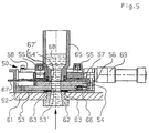
- FIG. 5 shows a slide closure 50 which is in the Difference from that of Figure 1 not on the mold 65, but on the suggestively shown casting furnace 61 is attached.
- the simplified illustrated mold 65 is accordingly at the remaining on the mold Slide lock 50 attached and released again.
- the slider closure 50 has a the casting furnace 61 mounted housing frame 52 in which a lower stationary refractory closure part 63 frontally of a clamping screw 66 or the like is fixed.
- the sliding above the closure part 63 arranged slide plate 54 is in a slide frame 56 held in turn by one of a drive member 69 adjustable slide 57 is taken.
- This Slider 57 is guided on slide rails 58, the top of Case frame 52 are attached.
- the slide plate 54 and the adjacent thereto Locking part 53, which form the closing surface are each provided with such passage openings 53 ', 54', that they are starting from the closing surface in diameter are extended upwards or downwards. This can be the in the passage opening 54 'of the slide plate 54th solidified melt when removing the mold 65 easily be taken out.
- a refractory Plate unit provided, which consists of at least one stätiondid Closure part 21, 22, 42, 53 and a slide plate 24, 54 exists in which the following material combinations used in the production:
- the invention is with the embodiments explained above sufficiently demonstrated.
- the construction of the casting furnace with the riser can of course other than look like this.
- the riser could even an upper plane end face and thus the Make a closure part on which the slide plate would be slidably arranged.
Abstract
Description
Die Erfindung betrifft einen Schieberverschluss zum Vergiessen von Metallschmelze, mit wenigstens einem stationären Verschlussteil an einer Giessform oder dergleichen, sowie mit einer zu diesem beweglichen Schieberplatte, sowie eine dazugehörige feuerfeste Platteneinheit.The invention relates to a slide closure for casting of molten metal, with at least one stationary one Closure part on a mold or the like, as well as with this movable slide plate, as well an associated refractory plate unit.
Bei einem bekannten Schieberverschluss für eine Druckgiessseinrichtung nach der Druckschrift CH-A-415 972 ist das Steigrohr eines Giessofens am oberen Ende mit einer den Schmelzofen abdichtenden Abdeckplatte versehen. Auf dieser Abdeckplatte ist ein Schieberverschluss mit einer feststehenden Platte, darüber einer Schieberplatte und einem oberhalb dieser vorhandenen Blockteil angeordnet, auf welchen die Giessform stellbar ist.In a known slide closure for a die casting device according to document CH-A-415 972 the riser of a casting furnace at the top with a provided the melting furnace sealing cover plate. On This cover plate is a slider closure with a fixed plate, above a slide plate and arranged above this existing block part, on which the mold is adjustable.
Bei einem anderen Schieberverschluss gemäss der Druckschrift DE-A-12 93 962 ist derselbe auf der Unterseite der Giessform montiert. Der Schieberverschluss ist hierbei mit einem unteren Abschlussteil, der Schieberplatte und einer oberhalb dieser befindlichen stationären Platte zusammengesetzt. In another slide closure according to the document DE-A-12 93 962 is the same on the underside of Mold installed. The slide lock is here with a lower end part, the slide plate and a assembled above this stationary plate.
Bei diesen bekannten Schieberverschlüssen besteht der grundsätzliche Nachteil darin, dass eine Dichtheit zwischen der Schieberplatte und dem unterhalb bzw. über ihr befindlichen Teil, mit dem sie jeweils beim Öffnen bzw. Schliessen in Gleitkontakt steht, nicht gewährleistet ist. Hieraus kann zwischen diesen sehr leicht Metallschmelze, welche üblicherweise eine geringe Viskosität aufweist, einfliessen. Zwischen diese Platten eingezogene Schmelze verfestigt sich in der Regel schnell, was bereits nach wenigen Verschiebebewegungen zu einem Blockieren der Schieberplatte führen kann.In these known slide closures consists of fundamental disadvantage in that a tightness between the slide plate and the below or above it part, with which they each open or Closing is in sliding contact, is not guaranteed. From this, between these very easily molten metal, which usually has a low viscosity, incorporated. Melt drawn in between these plates usually solidifies quickly, which is already after few moves to block the Slider plate can lead.
Aus der DE-A-33 22 542 ist ebenfalls ein Schieberverschluss mit zwei Platten bekannt. Bei diesem Verschieberverschluss werden die Platten mittels eines Druckzylinders aneinander gepresst, die über die Gießform wirken. Diese Art der Verspannung der Schieberplatten über die Gießform ist nachteilig, da gerade bei großen Gießformen, wie sie beispielsweise für die Herstellung von Motorblöcken genutzt werden, ein solches Andocken des Druckmittelzylinders an der Gießform schon aufgrund des schwer zu beherrschenden Gewichts und der Größe der Form unerwünscht ist. Es kann darüber hinaus auch keine sichere Dichtung zwischen den Platten gewährleistet werden.From DE-A-33 22 542 is also a slide closure known with two plates. In this slide closure the plates are joined together by means of a printing cylinder pressed, which act on the mold. This kind of Bracing the slide plates on the mold is disadvantageous, especially with large molds, as they used for example for the production of engine blocks be such a docking of the pressure cylinder to the Casting already because of the difficult to control Weight and size of the mold is undesirable. It can beyond that also no safe seal between the Panels are guaranteed.
In der US-A-5,400,930 ist schließlich ein Schiebeverschluss beschrieben, bei dem zwei gegeneinander verschiebbare Platten in einem Gehäuse angeordnet sind. Die Platten sind von Federn auf nicht näher dargestellte Weise aneinandergepresst. Das Gehäuse seinerseits ist in einem weiteren Gehäuse angeordnet und von Federn derart nach oben gepresst, dass die obere Platte eine Hülse im Behälter dicht anschließt. Der Behälter ist in herkömmlicher Weise auf der Oberseite des Schiebeverschlusses angeordnet. Die Schmelze fließt durch den Verschluss nach unten.In US-A-5,400,930, finally, a sliding closure described, in which two mutually displaceable Plates are arranged in a housing. The plates are of springs in a manner not shown pressed together. The housing in turn is in one arranged further housing and springs so upwards pressed that the top plate a sleeve in the container tight followed. The container is in the conventional manner on the Top of the sliding closure arranged. The melt flows down through the closure.
Der vorliegenden Erfindung wurde demgegenüber die Aufgabe zugrundegelegt, einen Schieberverschluss zu schaffen, welcher derart ausgestaltet ist, dass sich mit ihm ein zuverlässiger und wirtschaftlicher Betrieb einer Druckgiesseinrichtung oder dergleichen insgesamt ergibt und hierbei dessen Schieberplatte bzw. Verschlussteile eine lange Haltbarkeit aufweisen sollen.The present invention has the object based on creating a slide closure, which is designed so that with him a reliable and economical operation of a die casting device or the like in total and here the slide plate or closure parts a long Durability should have.
Diese Aufgabe wird erfindungsgemäß durch einen Schieberverschluss mit den Merkmalen des Anspruchs 1 gelöst. Vorteilhafte Ausgestaltungen eines erfindungsgemäßen Schieberverschlusses sind in den abhängigen Ansprüchen angegeben.This object is achieved by a slide closure solved with the features of claim 1. advantageous Embodiments of a slider closure according to the invention are specified in the dependent claims.
Mit diesem erfindungsgemässen Schieberverschluss sind optimale Voraussetzungen für ein wirtschaftliches Einsetzen eines Schieberverschlusses in einer solchen Druckgiesseinrichtung oder dergleichen geschaffen worden. Die Schieberplatte und die Verschlussteile können hierbei ohne Auswechslung bis zu mehreren hundert Eingüssen von Schmelze in die Giessform oder dergleichen verwendet werden. With this novel slider closure are optimal Requirements for an economical insertion a slider closure in such Druckgiesseinrichtung or the like has been created. The slide plate and the closure parts can do this without replacement up to several hundred sprues of melt be used in the mold or the like.
Bei einer sehr vorteilhaften Ausführung ist ein an der Giessform oder dergleichen befestigbarer Gehäuserahmen vorgesehen, in dem ein lösbares Gehäuseteil fixiert ist, an welchem die Federorgane gehalten und der stationäre Verschlussteil sowie die Schieberplatte aufnehmbar sind. Mit dieser Wegnehmbarkeit des Gehäuseteils vom Gehäuserahmen kann eine sehr einfache und schnelle Demontage bzw. Montage des Verschlusses an der Giessform erzielt werden.In a very advantageous embodiment is an on the Mold or the like attachable housing frame provided in which a detachable housing part is fixed, on which the spring organs held and the stationary Locking part and the slide plate are receivable. With this removability of the housing part of the housing frame can be a very simple and quick disassembly or Assembly of the closure can be achieved on the mold.
Für eine maximal mögliche Standzeit weisen die feuerfeste Schieberplatte und das wenigstens eine Verschlussteil als Hauptbestandteil Graphit, Al-Titanat oder Zirkon auf.For a maximum possible service life, the refractory Slide plate and the at least one closure part as Main component graphite, al-titanate or zirconium on.
Ausführungsbeispiele sowie weitere Vorteile der Erfindung sind anhand der Zeichnung näher erläutert. Es zeigt:
- Fig.1
- einen Querschnitt eines Schieberverschlusses einer teilweise dargestellten Druckgiesseinrichtung nach der Erfindung;
- Fig.2
- eine Draufsicht des Schieberverschlusses gemäss Fig.1;
- Fig.3
- einen Längsschnitt des Schieberverschlusses gemäss Fig.1;
- Fig.4
- einen teilweisen Querschnitt eines Schieberverschlusses, und
- Fig.5
- einen Längsschnitt einer weiteren Variante eines Schieberverschlusses.
- Fig.1
- a cross section of a slide closure of a partially illustrated die casting device according to the invention;
- Fig.2
- a plan view of the slide closure according to Fig.1;
- Figure 3
- a longitudinal section of the slide closure according to Fig.1;
- Figure 4
- a partial cross section of a slide closure, and
- Figure 5
- a longitudinal section of another variant of a slide closure.
Fig.1 bis Fig.3 zeigen einen Schieberverschluss 20, der
zum Öffnen und Schliessen einer Durchgangsöffnung 13, 14
dient. Der Schieberverschluss 20 weist ein oberes und ein
unteres stationäres Verschlussteil 21, 22 sowie eine zwischen
diesen bewegliche Schieberplatte 24 auf, wobei diese
mit der Schmelze in Berührung gelangenden Teile aus einem
feuerfesten Material hergestellt sind.Figures 1 to 3 show a
Andeutungsweise ist von einer Druckgiesseinrichtung, welche
vorzugsweise zum steigenden Giessen einer
Leichtmetall-Legierung dient, das obere Ende Steigrohres
11, 12 von einem Giessofen ersichtlich, durch welches die
Schmelze nach oben in eine ansatzweise gezeigte Giessform
15 gebracht wird, hierzu je eine Durchgangsöffnung 13, 14
vorgesehen ist, wobei zwischen dem Steigrohr 11, 12 und
der Giessform 15 der Schieberverschluss 20 mit dem Verschlussteil
21 und der Schieberplatte 24 angeordnet ist.Andeutungsweise is of a Druckgiesseinrichtung, which
preferably for the rising pour one
Alloy alloy is used, the
Die Schieberplatte 24 ist mittels Federorganen
25 an das obere stationäre Verschlussteil 21 oder
durch andere Mittel an das untere Verschlussteil 22 anpressbar.
Das obere Verschlussteil 21 und die unterhalb
diesem gleitende Schieberplatte 24 sind von den Federorganen
25 aneinander gepresst und der Giessform 15 zugeordnet,
das derweil das untere Verschlussteil 22 dem Steigrohr
11, 12 zugeordnet ist. Die Schieberplatte 24 ist beim
Aufsetzen der Giessform 15 auf den Giessofen dicht auf die
obere Gleitfläche 22' des Verschlussteils 22 angepresst,
wobei die Mittel für dieses Anpressen durch das Eigengewicht
der Giessform 15 und/oder durch ein zusätzliches
nicht näher gezeigtes Verspannmittel vorgesehen sein können.
Dieses Verspannmittel kann beispielsweise ein Andockmechanismus
sein, mittels dem die Giessform auf dem Ofen
positioniert und festgespannt wird. The
Das untere Verschlussteil 22 weist einen zu der Oberseite
16' des Steigrohres überstehenden Kragen 22" auf, der
eine solche Höhe und Breite aufweist, dass die Federorgane
25 mit Kipphebeln 26 die Schieberplatte 24 beidseitig untergreifen
können. Im Prinzip könnte auch die Schieberplatte
24 auf ihrer Unterseite einen entsprechenden Kragen
aufweisen.The
Bei einer im Rahmen der Erfindung sehr vorteilhaften Ausführung
ist ein an der Giessform 15 oder dergleichen befestigbarer
Gehäuserahmen 32 vorgesehen, in dem ein lösbares
Gehäuseteil 35 fixiert ist, an welchem die Federorgane
25 gehalten und das stationäre Verschlussteil 21
sowie die Schieberplatte 24 aufnehmbar sind.In a very advantageous embodiment of the invention
is a fastened to the
Der Gehäuserahmen 32 und das in ihm lösbare Gehäuseteil 35
weisen beidseitig miteinander korrespondierende Führungsflächen
33, 34 auf, wobei die eine Führungsfläche des Gehäuserahmens
32 derart annähernd in ihrer Längsausdehnung
verschiebbar gehalten ist, dass das Gehäuseteil 35 in ihm
verspannt bzw. von demselben gelöst werden kann.The
Zu diesem Zwecke ist die Führungsfläche 33 des Gehäuserahmens
32 von einem an einer Führungsstange 36 vorstehenden
Keil 33' gebildet. Diese Führungsstange 36 ist in dem Gehäuserahmen
32 längsverschiebbar gehalten und kann von
ausserhalb des Rahmens 32 in eine das Gehäuseteil 35 verspannende
Position 36.2, wie dargestellt, bzw. in eine
gelöste Position 36.1 geschoben werden, bei welcher das
Gehäuseteil 35 aus dem Rahmen 32 insbesondere für einen
Wechsel der Platten 21, 24 herausgenommen werden kann,
indessen der Rahmen 32 an der Giessform oder dergleichen
verbleibt. Die Führungsflächen 33 des Keils 33' und des
Gehäuseteils 35 sind zu der Verschieberichtung des Keils
33' in einem Winkel von einigen Graden angeordnet, so dass
in der Position 36.2 eine nicht lösende Keilverspannung
entsteht.For this purpose, the
Auf der gegenüberliegenden Seite sind die Führungsflächen
34 parallel zu der Verschieberichtung der Führungsstange
36 und im Querschnitt betrachtet, mit einer Schräge versehen,
damit das Gehäusteil 35 in den Rahmen 32 quasi einhängt
werden kann und er anschliessend durch Verschieben
des Keils 33' darin fixiert ist.On the opposite side are the
Das Steigrohr weist ein feuerfestes Giessrohr 11 und ein
dieses haltendes Metallrohr 12 mit einem oberen Flansch
12' auf, der auf einem Balg 17 befestigt ist. Dieser vorteilhaft
aus einem Metallblech hergestellte Balg 17 ist
mit einer solchen Steifigkeit versehen, dass mit dem unteren
Verschlussteil 22 eine beschränkte schwimmende Lagerung
gebildet ist, damit ein ganzflächiges Anliegen beim
Andrücken der Schieberplatte 24 gegen dieses Verschlußteil
22 und damit eine optimale Abdichtung zwischen den beiden
gewährleistet ist. Auf der Unterseite liegt das
Verschlussteil 22 ausserdem dichtend an einem im Metallrohr
12 gehaltenen feuerfesten Giessrohr 11 an, welches
mit seinem unteren Ende in die Schmelze ragt.The riser has a
Die Federorgane 25 weisen - wie dies auch in Fig.2
ersichtlich ist - beidseitig zu der Platte 24 je einen
Kipphebel 26 auf, der jeweils an Laschen 28 gelenkig gelagert
und von Federelementen 29 auf der der Platte 24 abgekehrten
Seite beaufschlagt ist, derart, dass die vorderen
Enden der Kipphebel 26 die Schieberplatte nach oben gegen
das Verschlussteil 21 drücken, welches in einem Gehäuserahmen
32 gehalten ist. Der Gehäuserahmen 32 ist seinerseits
auf der Unterseite der Giessform 15 befestigt. Ferner
ist noch eine mit der Schieberplatte stirnseitig gekoppelte
Antriebsstange 33 angedeutet, die einem nicht
näher gezeigten Antriebsorgan zugehört.The
Diese Druckgiesseinrichtung zeichnet sich dadurch aus, dass die nacheinander mit Schmelze zu füllenden Giessformen einfach und schnell auf dem Giessofen positioniert, gefüllt und durch eine nächste Giessform ersetzt werden können.This pressure casting device is characterized by that the successively to be filled with melt molds easily and quickly positioned on the casting furnace, filled and replaced by a next mold can.
Gemäss Fig. 3 ist der Gehäuserahmen 32 mit seiner Unterseite
32' auf der zum Antriebsorgan abgekehrten Seite vorzugsweise
oberhalb der unteren Gleitfläche 24' der Schieberplatte
24 angeordnet. Hierdurch kann die Giessform 15
zusammen mit dem auf ihrer Unterseite befestigten Schiebeverschluss
20 in Längsrichtung der Schieberplatte 24 in
der Weise herangeführt werden, dass der Kragen 22" des
zum Giessofen gehörenden Verschlussteils 22 zwischen die
Kipphebel 26 zu liegen kommt und die Giessform 15 nach
Erreichen der Giessposition auf dieses Verschlussteil 22
abgesenkt werden kann.According to FIG. 3, the
Fig. 4 zeigt eine Variante einer Druckgiesseinrichtung,
welche an sich gleich wie diejenige nach Fig.1 aufgebaut
ist, daher auf die obigen Erläuterungen verwiesen wird.
Der einzige Unterschied besteht darin, dass das untere
stationäre Verschlussteil 42 nicht dem Steigrohr 41, sondern
der Giessform zugeordnet ist. Dementsprechend sind
das obere und das untere Verschlussteil 21, 42 als auch
die Schieberplatte 24 von Kipphebeln 46 der Federorgane 45
im Gehäuserahmen 32 gegeneinander verspannt. Dieses untere
Verschlussteil 42 kommt beim Heranführen der Giessform auf
den vorstehenden Kragen 41' des Steigrohres 41 zu liegen.
Dies bietet den Vorteil, dass keine Verschiebung zwischen
diesen beiden stattfindet und dass zwischen der Schieberplatte
24 und dem oberen bzw. dem unteren Verschlussteil
21, 42 eine definierte Verspannkraft vorliegt.4 shows a variant of a pressure casting device,
which in itself the same as that of Fig.1 constructed
is therefore referred to the above explanations.
The only difference is that the lower one
Fig. 5 zeigt einen Schieberverschluss 50, der im
Unterschied zu demjenigen nach Fig.1 nicht an der Giessform
65, sondern auf dem andeutungsweise gezeigten Giessofen
61 befestigt ist. Die vereinfacht dargestellte Giessform
65 wird demgemäss an dem an der Giessform verbleibenden
Schieberverschluss 50 befestigt und wieder gelöst.FIG. 5 shows a
Zweckmässigerweise hat der Schieberverschluss 50 einen auf
dem Giessofen 61 befestigten Gehäuserahmen 52, in dem ein
unteres stationäres feuerfestes Verschlussteil 63
stirnseitig von einer Spannschraube 66 oder dergleichen
fixiert ist. Die oberhalb des Verschlussteiles 63 gleitend
angeordnete Schieberplatte 54 ist in einem Schieberrahmen
56 gehalten, der seinerseits von einem von einem Antriebsorgan
69 verstellbaren Schieber 57 mitgenommen ist. Dieser
Schieber 57 ist auf Gleitschienen 58 geführt, die oben am
Gehäuserahmen 52 befestigt sind. Zwischen der Schieberplatte
54 und der Giessform 65 als auch zwischen dem Verschlussteil
53 und dem Steigrohr 62 sind ferner noch Abdichtungen
63, 64 vorgesehen.Conveniently, the
Erfindungsgemäss sind zwischen der Giessform 65 und dem
Giessofen 61 Federorgane 55 angeordnet, die vorliegend im
Schieber 57 integriert sind und eine Verspannung der
Schieberplatte 54 mit dem Verschlussteil 53 bewirken. Mit
dieser Anordnung lassen sich mehrere hundert Füllungen der
Giessformen ausführen, ohne dass die Schieberplatte 54
oder das Verschleissteil 53 ausgewechselt werden müssten.According to the invention are between the
Es ist ferner andeutungsweise noch die Schmelze 68 während
dem Auffüllvorgang dargestellt. Sobald die Giessform 65
voll ist, wird dieselbe vom angesteuerten Antriebsorgan 69
zusammen mit der Schieberplatte 54 in die Schliessstellung
geschoben. Eine Zufuhrleitung 67 für ein Kühlmittel oberhalb
der Schieberplatte 54 in eine die Mündungsöffnung der
Giessform 65 umgebenden Ringnut 67' ermöglicht ein
beschleunigtes Abkühlen und somit ein schnelles Erstarren
der Schmelze 68, so dass die Giessform vom Schieberverschluss
50 weggenommen und eine neue leere Giessform
auf die Schieberplatte gesetzt werden kann.It is also hinted still the
Die Schieberplatte 54 bzw. das zu ihr angrenzende
Verschlussteil 53, welche die Schliessfläche bilden, sind
jeweils mit solchen Durchgangsöffnungen 53', 54' versehen,
dass sie ausgehend von der Schliessfläche im Durchmesser
nach oben bzw. nach unten erweitert sind. Damit kann die
in der Durchgangsöffnung 54' der Schieberplatte 54
erstarrte Schmelze beim Wegnehmen der Giessform 65 problemlos
herausgenommen werden.The
Als weiterer Beitrag für die Wirtschaftlichkeit der erfindungsgemässen
Druckgiesseinrichtung ist eine feuerfeste
Platteneinheit vorgesehen, die aus wenigstens einem stätionären
Verschlussteil 21, 22, 42, 53 und einer Schieberplatte
24, 54 besteht, bei denen die folgenden Materialkombinationen
bei der Herstellung verwendet werden: As a further contribution to the economy of the inventive
Die casting device is a refractory
Plate unit provided, which consists of at least one
Bei der Schieberplatte 24, 54 wird als Hauptbestandteil
Graphit und bei dem wenigstens einen angrenzenden stationären
Verschlussteil 21, 22, 42, 53 wird als Hauptbestandteil
Graphit, Al-Titanat oder Zirkon verwendet. Selbstverständlich
kann dies auch im umgekehrten Sinne vorgesehen
sein, d.h. für das Verschlussteil wird Graphit und für die
Schieberplatte Graphit, Al-Titanat oder Zirkon verwendet.When the
Die Erfindung ist mit den oben erläuterten Ausführungsbeispielen ausreichend dargetan. Die Konstruktion des Giessofens mit dem Steigrohr kann selbstverständlich anders als dargestellt aussehen. Im Prinzip könnte das Steigrohr selbst eine obere plane Stirnfläche und damit das Verschlussteil bilden, auf welchem die Schieberplatte gleitend angeordnet wäre.The invention is with the embodiments explained above sufficiently demonstrated. The construction of the casting furnace with the riser can of course other than look like this. In principle, the riser could even an upper plane end face and thus the Make a closure part on which the slide plate would be slidably arranged.
Claims (12)
- Sliding closure for casting molten metal for a die-casting apparatus, having at least one stationary closure part (21, 42, 53) which can be connected to a casting mould (15) or the like of the die-casting apparatus, and a sliding plate (24, 54) which is movable relative to the stationary closure part (21, 42, 53) and can be connected to a riser tube (11, 12, 62) of a casting furnace (61) belonging to the die-casting apparatus, the sliding plate (24, 54) and the at least one stationary closure part being tensed against one another by means of spring members (25, 45, 55) or other means, characterised in that, in the fully mounted state on the die-casting apparatus, the spring members (25, 45, 55) which are provided for tensing the at least one closure part (21, 42, 53) against the sliding plate are arranged on the sliding closure between the casting mould and the riser tube (11, 12, 62) of the casting furnace (61).
- Sliding closure according to Claim 1, characterised in that a housing frame (32) able to be fastened to the casting mould (15) or the like is provided, in which housing frame (32) is fixed a detachable housing part (35) on which the spring members (25) are held and in which the stationary closure part (21) and the sliding plate (24) can be received.
- Sliding closure according to Claim 2, characterised in that the housing frame (32) and the housing part (35) which is detachably held therein have at both ends guiding faces (33, 34) which correspond to one another, with one guiding face on the housing frame (32) being held to be displaceable approximately in its longitudinal direction in such a way that the housing part (35) can be tensed in the housing frame (32) or detached from it.
- Sliding closure according to Claim 3, characterised in that the guiding face on the housing frame (32) is formed on a wedge (33') projecting from a mounting rod (36), the mounting rod (36) having the wedge (33') being longitudinally displaceable in the housing frame (32) to a position (36.2) in which the housing part (35) is tensed or to a position (36.1) in which the housing part (35) is released.
- Sliding closure according to one of the foregoing claims, characterised in that the lower closure part (22) has a collar (22") which projects relative to the top face (16) of a casting furnace or the like, which collar (22") is of a height and width such that the tilting levers (26) of the spring members (25) are able to fit under the sliding plate (24) on both sides.
- Sliding closure according to one of the foregoing claims, characterised in that, at the end remote from the actuating member of the sliding plate (24), the underside (32') of the housing frame (32) is preferably arranged above the lower sliding face (24') of the sliding plate (24).
- Sliding closure according to one of the foregoing claims, characterised in that the upper and lower closure parts (21, 42) and also the sliding plate (24) are tensed against one another, in the housing frame (32) fastened to the casting mould (15), by the spring members (45).
- Sliding closure according to Claim 1, characterised in that a housing frame (52) fastened to the casting furnace (61) or the like is provided, in which housing frame (52) is fixed a refractory lower stationary closure part (63), whereas the sliding plate (54) which is arranged to slide above the closure part (63) is held in a sliding frame (56) which in turn is entrained by a slider (57), the sliding plate (54) being tensed against the closure part (63) by spring members (55) which are built into the slider (57).
- Sliding closure according to one of the foregoing claims, characterised in that a feed line (67), and an annular groove (67') for a coolant which is connected thereto and surrounds the opening at the mouth of the casting mould (65) or the like, are arranged above the sliding plate (54).
- Sliding closure according to one of the foregoing claims, characterised in that the sliding plate (24, 54) and the at least one adjacent closure part (21, 22, 42, 53) have as a main constituent graphite, aluminium titanate or zirconium.
- Sliding closure according to Claim 10, characterised in that the sliding plate (54) and the closure part (53) adjacent thereto, which form the closing face, are provided with respective openings (54', 53') for passage through which are such that, starting from the closing face, they become wider in diameter in the upward and downward directions respectively.
- Sliding closure according to Claim 10 or 11, characterised in that the sliding plate (24, 54) has graphite as a main constituent and the at least one adjacent closure part (21, 22, 42, 53) has graphite, aluminium titanate or zirconium as a main constituent, or vice versa.
Priority Applications (1)
| Application Number | Priority Date | Filing Date | Title |
|---|---|---|---|
| SI200130340T SI1299201T1 (en) | 2000-07-12 | 2001-07-07 | Sliding closure for casting molten metal |
Applications Claiming Priority (3)
| Application Number | Priority Date | Filing Date | Title |
|---|---|---|---|
| DE10033904 | 2000-07-12 | ||
| DE10033904A DE10033904A1 (en) | 2000-07-12 | 2000-07-12 | Slider closure for casting molten metal, as well as an associated fireproof plate unit |
| PCT/EP2001/007822 WO2002004148A1 (en) | 2000-07-12 | 2001-07-07 | Sliding closure for casting molten metal and corresponding refractory plate unit |
Publications (2)
| Publication Number | Publication Date |
|---|---|
| EP1299201A1 EP1299201A1 (en) | 2003-04-09 |
| EP1299201B1 true EP1299201B1 (en) | 2005-02-16 |
Family
ID=7648700
Family Applications (1)
| Application Number | Title | Priority Date | Filing Date |
|---|---|---|---|
| EP01957934A Expired - Lifetime EP1299201B1 (en) | 2000-07-12 | 2001-07-07 | Sliding closure for casting molten metal |
Country Status (14)
| Country | Link |
|---|---|
| US (1) | US6978980B2 (en) |
| EP (1) | EP1299201B1 (en) |
| AT (1) | ATE289239T1 (en) |
| AU (2) | AU7972201A (en) |
| BR (1) | BR0112412A (en) |
| CA (1) | CA2414943A1 (en) |
| DE (2) | DE10033904A1 (en) |
| DK (1) | DK1299201T3 (en) |
| ES (1) | ES2238465T3 (en) |
| HU (1) | HU226153B1 (en) |
| MX (1) | MXPA03000287A (en) |
| PL (1) | PL198757B1 (en) |
| SK (1) | SK286971B6 (en) |
| WO (1) | WO2002004148A1 (en) |
Families Citing this family (10)
| Publication number | Priority date | Publication date | Assignee | Title |
|---|---|---|---|---|
| DE10033902C1 (en) * | 2000-07-12 | 2001-11-22 | Vaw Ver Aluminium Werke Ag | Casting/low pressure casting comprises pushing together two opening sections of a passage channel directly after casting so that an opening section lying above remains connected to the casting opening |
| DE10033903C1 (en) * | 2000-07-12 | 2001-11-29 | Vaw Ver Aluminium Werke Ag | Bottom casting plant for light alloys has closure plate fitted with two sliding plates which produce staggered connection between furnace and mold when opened |
| WO2004110682A1 (en) * | 2003-06-14 | 2004-12-23 | Stopinc Aktiengesellschaft | Casting system, especially for die casting a metal melt |
| DE102004043444B3 (en) * | 2004-09-06 | 2006-06-14 | Hydro Aluminium Alucast Gmbh | Method and apparatus for casting molten metal |
| US7743790B2 (en) * | 2008-02-20 | 2010-06-29 | Varian, Inc. | Shutter and gate valve assemblies for vacuum systems |
| JP5309011B2 (en) * | 2009-12-25 | 2013-10-09 | 品川リフラクトリーズ株式会社 | Automatic surface pressure load slide valve device and surface pressure load method thereof |
| EP2979777B1 (en) * | 2013-03-27 | 2018-10-17 | Krosakiharima Corporation | Sliding nozzle device |
| KR101719801B1 (en) * | 2013-09-29 | 2017-03-24 | 어플라이드 머티어리얼스, 인코포레이티드 | Removable isolation valve shield insert assembly |
| CN105750527A (en) * | 2016-04-19 | 2016-07-13 | 哈尔滨东安发动机(集团)有限公司 | Method for sealing riser tube for casting |
| CN110790303A (en) * | 2019-11-19 | 2020-02-14 | 武汉拓材科技有限公司 | High-purity gallium oxide synthetic furnace |
Family Cites Families (25)
| Publication number | Priority date | Publication date | Assignee | Title |
|---|---|---|---|---|
| DE1293962B (en) * | 1961-10-23 | 1969-04-30 | Amsted Ind Inc | Plate slide lock for the mold of a low pressure casting system |
| CH415972A (en) * | 1964-03-06 | 1966-06-30 | Alusuisse | Die casting process and device for carrying out the process |
| US3435884A (en) * | 1966-06-01 | 1969-04-01 | United Eng Foundry Co | Gate positioning device for article-casting machine |
| US3627018A (en) * | 1969-09-23 | 1971-12-14 | Amsted Ind Inc | Method for producing castings in a permanent mold |
| US3905419A (en) * | 1970-09-29 | 1975-09-16 | Gravicast Patent Gmbh | Device for rise casting into a mold |
| US4063668A (en) * | 1971-06-07 | 1977-12-20 | United States Steel Corporation | Ladle gate valve |
| DE2646187A1 (en) * | 1976-10-13 | 1978-04-20 | Ture Arvid Bertland | Low pressure casting of steel in moulds - where stand pipe contains sliding stopper which chills metal in ingate (SW 8.11.76) |
| DE2918344A1 (en) * | 1979-05-07 | 1980-11-20 | Metacon Ag | SLIDING CLOSURE FOR THE TAPPING CHANNEL OF A METALLURGICAL OVEN OR CONTAINER |
| CH653933A5 (en) * | 1981-05-19 | 1986-01-31 | Stopinc Ag | SLIDING CLOSURE FOR MELTING CASES. |
| US4556157A (en) * | 1982-05-24 | 1985-12-03 | Flo-Con Systems, Inc. | Pressure fluid teeming valve and method |
| DE3322542A1 (en) * | 1983-06-23 | 1985-01-10 | Piel & Adey, 5650 Solingen | Process and apparatus for the low pressure casting of articles from metals |
| DE3835687A1 (en) * | 1988-10-20 | 1990-04-26 | Cerafer Sarl | SLIDING LOCK FOR METALLURGICAL VESSELS |
| IT1234484B (en) * | 1989-02-15 | 1992-05-18 | Sirma Nuova | PERFECTED DRAWER SHUTTER WITH THREE PLATES, PARTICULARLY FOR BASKET. |
| US5044533A (en) * | 1990-10-01 | 1991-09-03 | Flo-Con Systems, Inc. | Clamp for bandless refractory and method |
| DE68911675T2 (en) * | 1989-06-02 | 1994-05-05 | Sanac Nuova Spa | Slider closure for ladles and similar devices. |
| DE4006064A1 (en) | 1990-02-26 | 1991-08-29 | Zimmermann & Jansen Gmbh | LOCKING DEVICE FOR THE FLOOR POUR OPENING OF A WATER PAN |
| US5062553A (en) * | 1990-03-16 | 1991-11-05 | Flo-Con Systems, Inc. | Cantilever spring mount for sliding gate valve and method |
| ATE173967T1 (en) * | 1992-09-28 | 1998-12-15 | Vesuvius Italia Spa | SLIDE CLOSURE FOR METALLURGICAL VESSELS EQUIPPED WITH LATERAL TORSION RODS |
| JPH06134557A (en) * | 1992-10-23 | 1994-05-17 | Tokyo Yogyo Co Ltd | Sliding nozzle for molten metal incorporating vessel |
| US5350159A (en) * | 1993-02-18 | 1994-09-27 | Westinghouse Electric Corporation | On/off valve apparatus for use in conjunction with electromagnetic flow control device controlling the flow of liquid metal through an orifice |
| ATE220588T1 (en) * | 1993-04-19 | 2002-08-15 | Vesuvius France Sa | DEVICE AND METHOD FOR CASTING WITH A CEMENT-FREE CONNECTION OF THE SLIDING CLOSURE TO THE METALLURGICAL VESSEL |
| US5518154A (en) * | 1994-11-17 | 1996-05-21 | Usx Corporation | Gate and pour tube assembly for use in throttling gate valve |
| GB9509013D0 (en) * | 1995-05-03 | 1995-06-21 | Flogates Ltd | Improved sliding gate valve |
| GB9509014D0 (en) * | 1995-05-03 | 1995-06-21 | Flogates Ltd | Improved sliding gate valve |
| KR100551476B1 (en) * | 1998-07-26 | 2006-02-14 | 스토핑크 악티엔 게젤샤프트 | Sliding gate valve at the outlet of a container containing molten metal |
-
2000
- 2000-07-12 DE DE10033904A patent/DE10033904A1/en not_active Withdrawn
-
2001
- 2001-07-07 WO PCT/EP2001/007822 patent/WO2002004148A1/en active IP Right Grant
- 2001-07-07 DK DK01957934T patent/DK1299201T3/en active
- 2001-07-07 BR BR0112412-9A patent/BR0112412A/en not_active Application Discontinuation
- 2001-07-07 EP EP01957934A patent/EP1299201B1/en not_active Expired - Lifetime
- 2001-07-07 PL PL359486A patent/PL198757B1/en not_active IP Right Cessation
- 2001-07-07 HU HU0301547A patent/HU226153B1/en not_active IP Right Cessation
- 2001-07-07 AT AT01957934T patent/ATE289239T1/en not_active IP Right Cessation
- 2001-07-07 DE DE50105377T patent/DE50105377D1/en not_active Expired - Lifetime
- 2001-07-07 AU AU7972201A patent/AU7972201A/en active Pending
- 2001-07-07 ES ES01957934T patent/ES2238465T3/en not_active Expired - Lifetime
- 2001-07-07 US US10/312,801 patent/US6978980B2/en not_active Expired - Fee Related
- 2001-07-07 MX MXPA03000287A patent/MXPA03000287A/en active IP Right Grant
- 2001-07-07 CA CA002414943A patent/CA2414943A1/en not_active Abandoned
- 2001-07-07 SK SK23-2003A patent/SK286971B6/en not_active IP Right Cessation
- 2001-07-07 AU AU2001279722A patent/AU2001279722B2/en not_active Ceased
Also Published As
| Publication number | Publication date |
|---|---|
| MXPA03000287A (en) | 2004-12-13 |
| US6978980B2 (en) | 2005-12-27 |
| DE50105377D1 (en) | 2005-03-24 |
| BR0112412A (en) | 2003-05-27 |
| DK1299201T3 (en) | 2005-06-13 |
| DE10033904A1 (en) | 2002-01-31 |
| CA2414943A1 (en) | 2002-12-30 |
| US20040026467A1 (en) | 2004-02-12 |
| SK286971B6 (en) | 2009-08-06 |
| ATE289239T1 (en) | 2005-03-15 |
| HUP0301547A2 (en) | 2003-08-28 |
| PL198757B1 (en) | 2008-07-31 |
| WO2002004148A1 (en) | 2002-01-17 |
| SK232003A3 (en) | 2003-09-11 |
| HU226153B1 (en) | 2008-05-28 |
| EP1299201A1 (en) | 2003-04-09 |
| AU2001279722B2 (en) | 2005-04-21 |
| AU7972201A (en) | 2002-01-21 |
| PL359486A1 (en) | 2004-08-23 |
| ES2238465T3 (en) | 2005-09-01 |
Similar Documents
| Publication | Publication Date | Title |
|---|---|---|
| DE2545514C3 (en) | Sliding valve device for casting vessels provided with bottom outlet openings | |
| EP0468363B1 (en) | Apparatus for exchanging a pouring tube on a metallurgical vessel | |
| DE2620423A1 (en) | SLIDE PLATE UNIT FOR SLIDE LATCHES | |
| EP1299201B1 (en) | Sliding closure for casting molten metal | |
| EP0727268B1 (en) | Sliding closure system for a container holding a bath of molten metal | |
| WO2009127333A1 (en) | Sliding closure for a receptacle containing molten metal | |
| EP0819488B1 (en) | Sliding gate closure for a molten metal containing vessel | |
| DE1185340B (en) | Closing device for pouring ladles | |
| DE3512799C1 (en) | Sliding closure for metallurgical containers | |
| DE2918344C2 (en) | ||
| DE2024829B2 (en) | FLOOR SLIDER CLOSURE FOR A POUR | |
| DE2806919A1 (en) | Flat slide valve for pouring molten metal | |
| DE2840171B2 (en) | Closure device for the bottom outlet of pouring ladles | |
| DE2219064A1 (en) | METHOD AND DEVICE FOR REPLACING A HOLDER FOR A POUR PIPE ON A CASTING VESSEL PROVIDED WITH A BOTTOM SPOUT | |
| DE4403517A1 (en) | Gate valve | |
| EP2490846B1 (en) | Fireproof unit for a sliding closure at the spout of a container for metal melt | |
| DE10033902C1 (en) | Casting/low pressure casting comprises pushing together two opening sections of a passage channel directly after casting so that an opening section lying above remains connected to the casting opening | |
| DE3512798C1 (en) | Sliding closure for vessels containing molten metal | |
| DE2146677C3 (en) | Bottom slide lock on a casting vessel | |
| EP0445590A1 (en) | Slide gate nozzle for metallurgical vessels, in particular casting ladles | |
| DE4401825A1 (en) | Starting head for a continuous casting installation | |
| WO1992017298A1 (en) | Slide bolt for melting pots | |
| DE10033903C1 (en) | Bottom casting plant for light alloys has closure plate fitted with two sliding plates which produce staggered connection between furnace and mold when opened | |
| DE3526332A1 (en) | Press, especially pneumatic horizontal grape press | |
| DE3120053C2 (en) |
Legal Events
| Date | Code | Title | Description |
|---|---|---|---|
| PUAI | Public reference made under article 153(3) epc to a published international application that has entered the european phase |
Free format text: ORIGINAL CODE: 0009012 |
|
| 17P | Request for examination filed |
Effective date: 20021218 |
|
| AK | Designated contracting states |
Kind code of ref document: A1 Designated state(s): AT BE CH CY DE DK ES FI FR GB GR IE IT LI LU MC NL PT SE TR |
|
| AX | Request for extension of the european patent |
Extension state: AL LT LV MK RO SI |
|
| RAP1 | Party data changed (applicant data changed or rights of an application transferred) |
Owner name: STOPINC AKTIENGESELLSCHAFT Owner name: HYDRO ALUMINIUM DEUTSCHLAND GMBH |
|
| RIN1 | Information on inventor provided before grant (corrected) |
Inventor name: BOCK, RALF Inventor name: MUELLER, WOLFGANG Inventor name: AMSLER, HARRY Inventor name: PLATTNER, WERNER |
|
| RAP1 | Party data changed (applicant data changed or rights of an application transferred) |
Owner name: STOPINC AKTIENGESELLSCHAFT Owner name: HYDRO ALUMINIUM DEUTSCHLAND GMBH |
|
| 17Q | First examination report despatched |
Effective date: 20031031 |
|
| GRAP | Despatch of communication of intention to grant a patent |
Free format text: ORIGINAL CODE: EPIDOSNIGR1 |
|
| RTI1 | Title (correction) |
Free format text: SLIDING CLOSURE FOR CASTING MOLTEN METAL |
|
| GRAS | Grant fee paid |
Free format text: ORIGINAL CODE: EPIDOSNIGR3 |
|
| GRAA | (expected) grant |
Free format text: ORIGINAL CODE: 0009210 |
|
| AK | Designated contracting states |
Kind code of ref document: B1 Designated state(s): AT BE CH CY DE DK ES FI FR GB GR IE IT LI LU MC NL PT SE TR |
|
| AX | Request for extension of the european patent |
Extension state: RO SI |
|
| PG25 | Lapsed in a contracting state [announced via postgrant information from national office to epo] |
Ref country code: NL Free format text: LAPSE BECAUSE OF FAILURE TO SUBMIT A TRANSLATION OF THE DESCRIPTION OR TO PAY THE FEE WITHIN THE PRESCRIBED TIME-LIMIT Effective date: 20050216 Ref country code: FI Free format text: LAPSE BECAUSE OF FAILURE TO SUBMIT A TRANSLATION OF THE DESCRIPTION OR TO PAY THE FEE WITHIN THE PRESCRIBED TIME-LIMIT Effective date: 20050216 |
|
| REG | Reference to a national code |
Ref country code: GB Ref legal event code: FG4D Free format text: NOT ENGLISH |
|
| REG | Reference to a national code |
Ref country code: CH Ref legal event code: EP |
|
| REG | Reference to a national code |
Ref country code: IE Ref legal event code: FG4D Free format text: GERMAN |
|
| REF | Corresponds to: |
Ref document number: 50105377 Country of ref document: DE Date of ref document: 20050324 Kind code of ref document: P |
|
| PG25 | Lapsed in a contracting state [announced via postgrant information from national office to epo] |
Ref country code: GR Free format text: LAPSE BECAUSE OF FAILURE TO SUBMIT A TRANSLATION OF THE DESCRIPTION OR TO PAY THE FEE WITHIN THE PRESCRIBED TIME-LIMIT Effective date: 20050516 |
|
| REG | Reference to a national code |
Ref country code: SE Ref legal event code: TRGR |
|
| REG | Reference to a national code |
Ref country code: DK Ref legal event code: T3 |
|
| GBT | Gb: translation of ep patent filed (gb section 77(6)(a)/1977) |
Effective date: 20050523 |
|
| PG25 | Lapsed in a contracting state [announced via postgrant information from national office to epo] |
Ref country code: LU Free format text: LAPSE BECAUSE OF NON-PAYMENT OF DUE FEES Effective date: 20050707 Ref country code: CY Free format text: LAPSE BECAUSE OF FAILURE TO SUBMIT A TRANSLATION OF THE DESCRIPTION OR TO PAY THE FEE WITHIN THE PRESCRIBED TIME-LIMIT Effective date: 20050707 |
|
| PG25 | Lapsed in a contracting state [announced via postgrant information from national office to epo] |
Ref country code: PT Free format text: LAPSE BECAUSE OF FAILURE TO SUBMIT A TRANSLATION OF THE DESCRIPTION OR TO PAY THE FEE WITHIN THE PRESCRIBED TIME-LIMIT Effective date: 20050722 |
|
| PGFP | Annual fee paid to national office [announced via postgrant information from national office to epo] |
Ref country code: IE Payment date: 20050722 Year of fee payment: 5 |
|
| PG25 | Lapsed in a contracting state [announced via postgrant information from national office to epo] |
Ref country code: MC Free format text: LAPSE BECAUSE OF NON-PAYMENT OF DUE FEES Effective date: 20050731 |
|
| NLV1 | Nl: lapsed or annulled due to failure to fulfill the requirements of art. 29p and 29m of the patents act | ||
| REG | Reference to a national code |
Ref country code: ES Ref legal event code: FG2A Ref document number: 2238465 Country of ref document: ES Kind code of ref document: T3 |
|
| PGFP | Annual fee paid to national office [announced via postgrant information from national office to epo] |
Ref country code: BE Payment date: 20050914 Year of fee payment: 5 |
|
| PLBE | No opposition filed within time limit |
Free format text: ORIGINAL CODE: 0009261 |
|
| STAA | Information on the status of an ep patent application or granted ep patent |
Free format text: STATUS: NO OPPOSITION FILED WITHIN TIME LIMIT |
|
| 26N | No opposition filed |
Effective date: 20051117 |
|
| ET | Fr: translation filed | ||
| PG25 | Lapsed in a contracting state [announced via postgrant information from national office to epo] |
Ref country code: IE Free format text: LAPSE BECAUSE OF NON-PAYMENT OF DUE FEES Effective date: 20060707 |
|
| PG25 | Lapsed in a contracting state [announced via postgrant information from national office to epo] |
Ref country code: SE Free format text: LAPSE BECAUSE OF NON-PAYMENT OF DUE FEES Effective date: 20060708 |
|
| PG25 | Lapsed in a contracting state [announced via postgrant information from national office to epo] |
Ref country code: BE Free format text: LAPSE BECAUSE OF NON-PAYMENT OF DUE FEES Effective date: 20060731 |
|
| EUG | Se: european patent has lapsed | ||
| REG | Reference to a national code |
Ref country code: IE Ref legal event code: MM4A |
|
| REG | Reference to a national code |
Ref country code: SI Ref legal event code: KO00 Effective date: 20070405 |
|
| BERE | Be: lapsed |
Owner name: *STOPINC A.G. Effective date: 20060731 Owner name: *HYDRO ALUMINIUM DEUTSCHLAND G.M.B.H. Effective date: 20060731 |
|
| PGFP | Annual fee paid to national office [announced via postgrant information from national office to epo] |
Ref country code: CH Payment date: 20071205 Year of fee payment: 7 |
|
| PGFP | Annual fee paid to national office [announced via postgrant information from national office to epo] |
Ref country code: GB Payment date: 20080110 Year of fee payment: 7 |
|
| PGFP | Annual fee paid to national office [announced via postgrant information from national office to epo] |
Ref country code: DK Payment date: 20080731 Year of fee payment: 8 |
|
| REG | Reference to a national code |
Ref country code: CH Ref legal event code: PL |
|
| GBPC | Gb: european patent ceased through non-payment of renewal fee |
Effective date: 20080707 |
|
| PG25 | Lapsed in a contracting state [announced via postgrant information from national office to epo] |
Ref country code: CH Free format text: LAPSE BECAUSE OF NON-PAYMENT OF DUE FEES Effective date: 20080731 Ref country code: GB Free format text: LAPSE BECAUSE OF NON-PAYMENT OF DUE FEES Effective date: 20080707 Ref country code: LI Free format text: LAPSE BECAUSE OF NON-PAYMENT OF DUE FEES Effective date: 20080731 |
|
| PGFP | Annual fee paid to national office [announced via postgrant information from national office to epo] |
Ref country code: AT Payment date: 20090729 Year of fee payment: 9 |
|
| REG | Reference to a national code |
Ref country code: DK Ref legal event code: EBP |
|
| PG25 | Lapsed in a contracting state [announced via postgrant information from national office to epo] |
Ref country code: DK Free format text: LAPSE BECAUSE OF NON-PAYMENT OF DUE FEES Effective date: 20090731 |
|
| PG25 | Lapsed in a contracting state [announced via postgrant information from national office to epo] |
Ref country code: AT Free format text: LAPSE BECAUSE OF NON-PAYMENT OF DUE FEES Effective date: 20100707 |
|
| PGFP | Annual fee paid to national office [announced via postgrant information from national office to epo] |
Ref country code: TR Payment date: 20120614 Year of fee payment: 12 |
|
| PGFP | Annual fee paid to national office [announced via postgrant information from national office to epo] |
Ref country code: ES Payment date: 20120719 Year of fee payment: 12 Ref country code: IT Payment date: 20120720 Year of fee payment: 12 Ref country code: FR Payment date: 20120803 Year of fee payment: 12 |
|
| REG | Reference to a national code |
Ref country code: FR Ref legal event code: ST Effective date: 20140331 |
|
| PG25 | Lapsed in a contracting state [announced via postgrant information from national office to epo] |
Ref country code: IT Free format text: LAPSE BECAUSE OF NON-PAYMENT OF DUE FEES Effective date: 20130707 Ref country code: FR Free format text: LAPSE BECAUSE OF NON-PAYMENT OF DUE FEES Effective date: 20130731 |
|
| REG | Reference to a national code |
Ref country code: ES Ref legal event code: FD2A Effective date: 20141010 |
|
| PG25 | Lapsed in a contracting state [announced via postgrant information from national office to epo] |
Ref country code: ES Free format text: LAPSE BECAUSE OF NON-PAYMENT OF DUE FEES Effective date: 20130708 |
|
| PG25 | Lapsed in a contracting state [announced via postgrant information from national office to epo] |
Ref country code: TR Free format text: LAPSE BECAUSE OF NON-PAYMENT OF DUE FEES Effective date: 20130707 |
|
| PGFP | Annual fee paid to national office [announced via postgrant information from national office to epo] |
Ref country code: DE Payment date: 20170725 Year of fee payment: 17 |
|
| REG | Reference to a national code |
Ref country code: DE Ref legal event code: R119 Ref document number: 50105377 Country of ref document: DE |
|
| PG25 | Lapsed in a contracting state [announced via postgrant information from national office to epo] |
Ref country code: DE Free format text: LAPSE BECAUSE OF NON-PAYMENT OF DUE FEES Effective date: 20190201 |