EP1298765B1 - Methode zur Erzeugung optischer Strahlung geeignet zur Verwendung in einem Raman-Verstärkungsprozess und Pumpquelle für Raman-Verstärker - Google Patents
Methode zur Erzeugung optischer Strahlung geeignet zur Verwendung in einem Raman-Verstärkungsprozess und Pumpquelle für Raman-Verstärker Download PDFInfo
- Publication number
- EP1298765B1 EP1298765B1 EP01830618A EP01830618A EP1298765B1 EP 1298765 B1 EP1298765 B1 EP 1298765B1 EP 01830618 A EP01830618 A EP 01830618A EP 01830618 A EP01830618 A EP 01830618A EP 1298765 B1 EP1298765 B1 EP 1298765B1
- Authority
- EP
- European Patent Office
- Prior art keywords
- raman
- optical radiation
- medium
- additional
- radiation
- Prior art date
- Legal status (The legal status is an assumption and is not a legal conclusion. Google has not performed a legal analysis and makes no representation as to the accuracy of the status listed.)
- Expired - Lifetime
Links
Images
Classifications
-
- H—ELECTRICITY
- H01—ELECTRIC ELEMENTS
- H01S—DEVICES USING THE PROCESS OF LIGHT AMPLIFICATION BY STIMULATED EMISSION OF RADIATION [LASER] TO AMPLIFY OR GENERATE LIGHT; DEVICES USING STIMULATED EMISSION OF ELECTROMAGNETIC RADIATION IN WAVE RANGES OTHER THAN OPTICAL
- H01S3/00—Lasers, i.e. devices using stimulated emission of electromagnetic radiation in the infrared, visible or ultraviolet wave range
- H01S3/30—Lasers, i.e. devices using stimulated emission of electromagnetic radiation in the infrared, visible or ultraviolet wave range using scattering effects, e.g. stimulated Brillouin or Raman effects
- H01S3/302—Lasers, i.e. devices using stimulated emission of electromagnetic radiation in the infrared, visible or ultraviolet wave range using scattering effects, e.g. stimulated Brillouin or Raman effects in an optical fibre
-
- H—ELECTRICITY
- H01—ELECTRIC ELEMENTS
- H01S—DEVICES USING THE PROCESS OF LIGHT AMPLIFICATION BY STIMULATED EMISSION OF RADIATION [LASER] TO AMPLIFY OR GENERATE LIGHT; DEVICES USING STIMULATED EMISSION OF ELECTROMAGNETIC RADIATION IN WAVE RANGES OTHER THAN OPTICAL
- H01S3/00—Lasers, i.e. devices using stimulated emission of electromagnetic radiation in the infrared, visible or ultraviolet wave range
- H01S3/05—Construction or shape of optical resonators; Accommodation of active medium therein; Shape of active medium
- H01S3/06—Construction or shape of active medium
- H01S3/063—Waveguide lasers, i.e. whereby the dimensions of the waveguide are of the order of the light wavelength
- H01S3/067—Fibre lasers
- H01S3/06754—Fibre amplifiers
-
- H—ELECTRICITY
- H01—ELECTRIC ELEMENTS
- H01S—DEVICES USING THE PROCESS OF LIGHT AMPLIFICATION BY STIMULATED EMISSION OF RADIATION [LASER] TO AMPLIFY OR GENERATE LIGHT; DEVICES USING STIMULATED EMISSION OF ELECTROMAGNETIC RADIATION IN WAVE RANGES OTHER THAN OPTICAL
- H01S3/00—Lasers, i.e. devices using stimulated emission of electromagnetic radiation in the infrared, visible or ultraviolet wave range
- H01S3/09—Processes or apparatus for excitation, e.g. pumping
- H01S3/091—Processes or apparatus for excitation, e.g. pumping using optical pumping
- H01S3/094—Processes or apparatus for excitation, e.g. pumping using optical pumping by coherent light
- H01S3/094042—Processes or apparatus for excitation, e.g. pumping using optical pumping by coherent light of a fibre laser
- H01S3/094046—Processes or apparatus for excitation, e.g. pumping using optical pumping by coherent light of a fibre laser of a Raman fibre laser
-
- H—ELECTRICITY
- H01—ELECTRIC ELEMENTS
- H01S—DEVICES USING THE PROCESS OF LIGHT AMPLIFICATION BY STIMULATED EMISSION OF RADIATION [LASER] TO AMPLIFY OR GENERATE LIGHT; DEVICES USING STIMULATED EMISSION OF ELECTROMAGNETIC RADIATION IN WAVE RANGES OTHER THAN OPTICAL
- H01S3/00—Lasers, i.e. devices using stimulated emission of electromagnetic radiation in the infrared, visible or ultraviolet wave range
- H01S3/09—Processes or apparatus for excitation, e.g. pumping
- H01S3/091—Processes or apparatus for excitation, e.g. pumping using optical pumping
- H01S3/094—Processes or apparatus for excitation, e.g. pumping using optical pumping by coherent light
- H01S3/094096—Multi-wavelength pumping
-
- H—ELECTRICITY
- H01—ELECTRIC ELEMENTS
- H01S—DEVICES USING THE PROCESS OF LIGHT AMPLIFICATION BY STIMULATED EMISSION OF RADIATION [LASER] TO AMPLIFY OR GENERATE LIGHT; DEVICES USING STIMULATED EMISSION OF ELECTROMAGNETIC RADIATION IN WAVE RANGES OTHER THAN OPTICAL
- H01S3/00—Lasers, i.e. devices using stimulated emission of electromagnetic radiation in the infrared, visible or ultraviolet wave range
- H01S3/14—Lasers, i.e. devices using stimulated emission of electromagnetic radiation in the infrared, visible or ultraviolet wave range characterised by the material used as the active medium
- H01S3/16—Solid materials
- H01S3/1601—Solid materials characterised by an active (lasing) ion
- H01S3/1603—Solid materials characterised by an active (lasing) ion rare earth
- H01S3/1618—Solid materials characterised by an active (lasing) ion rare earth ytterbium
Definitions
- This invention relates to amplification techniques based on the Raman effect and was developed with particular reference to the need of developing broadband and high-power laser sources which can be used in Raman amplifiers for amplifying optical signals on fibers.
- Raman amplification techniques both distributed and discrete play an increasingly important role in overcoming the intrinsic limitations of traditional systems based, for example, on Erbium Doped Fiber Amplifiers (EDFA). In principle, this also refers to the aspects related to bandwidth and noise. Additionally, Raman amplification can be useful for eliminating or compensating EDFA gain irregularities (tilting and/or ripples) due to the presence of optical amplifiers (EDFA) in the transmission line.
- EDFA Erbium Doped Fiber Amplifiers
- the frequency/wavelength range in which the amplification effect is attained is identified in principle by the frequency of the source used as a pump. Consequently, in order to extend the frequency range for Raman amplification and to make the amplification action more regular in this frequency range, pumping with several sources working at different wavelengths can be resorted to. Each source consequently generates radiation at a wavelength suitable for producing a Raman gain in a different region of the electromagnetic spectrum. To fulfil the above requirement, it is mandatory to pump the medium in which the Raman effect is attained (hereinafter briefly called the "Raman medium") by using several pump wavelengths with suitable power levels.
- the objective is to approximate as closely as possible the ideal model of a single high-power source capable of generating a broadband output signal and preferably offering the possibility of implementing reliable control, both of the output power and of the wavelength in each frequency range concerned.
- Noise of the pump sources is another crucial factor which must be considered in Raman fiber amplifier design. This fact (described, for example, in the work by C.R.S. Fludger, et al., "Pump to Signal RIN Transfer in Raman Fibre Amplifiers", El. Lett. Vol. 37, No. 1, pg. 15-17, 4th January 2001 ) along with cost and dimension factors penalises both the solutions described above and other recently proposed solutions based on multiplexing two or more Raman fiber lasers.
- the invention relates to a process according to the preamble of claim 1, which is known, e.g. from EP-A-1 026 797 .
- the document CHERNIKOV S V ET AL:"Raman fibre laser operating at 1.24 micrometers” ELECTRONICS LETTERS, IEE STEVENAGE, GB, vol. 34, no. 7,2 April 1998 (1998-04-02), pages 680-681 is also of interest for the invention.
- the object of this invention is to provide a solution for making a broadband, low noise and high-power laser source for use as a pumping source for a Raman fibre amplifier, presenting broadband operation and high amplification gain. This both for distributed configurations and for discrete configurations.
- this object is achieved by a process whose characteristics are specifically recited in the Claim 1.
- This invention also relates to the corresponding source according to Claim 10 and to a Raman amplifier utilizing said source.
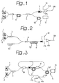
- reference PS indicates a broadband, high-power laser signal.
- the PS signal can be used as a pumping signal in a Raman effect amplifier RA inserted in a fiber optic signal transmission system to generate an amplified output signal OR from an input signal IR.
- the pumping signal PS can be a signal with a bandwidth of several tens of nanometres (e.g. in the range from 1420 and 1500 nanometres) with a power in the order of 1-3 watts.
- bandwidth and power criteria can be selectively increased or decreased according to the specific requirements of use.
- the general construction characteristics of the Raman amplifier RA are intrinsically known in technology and however not essential for understanding this implementation.
- the radiation PS is generated by a plurality of laser sources consisting of laser diodes 1, 2, ..., n operating as master oscillators in a general MOPA (Master Oscillator + Power Amplifier) configuration.
- MOPA Master Oscillator + Power Amplifier
- the diodes 1, 2 can consist of currently manufactured low-power laser diodes, e.g. FiTel FOL1402PMH-317-14XX or Sumitomo SLA5604-CD components.
- the diodes 1 and 2 are herein identified as "low-power" optical sources to indicate that the radiation individually output by each of the sources would singularly be insufficient to generate an appreciable Raman effect if injected in a corresponding medium.
- the concerned diodes 1, 2 can present an output power in the order of 150-180 mW, and in a way which is particularly advantageous (for the reasons which will be clarified below) the output power is selectively adjustable for each of the diodes 1, 2.
- diodes 1, 2, ... can present an output bandwidth in the order of 2-3 nanometres and, preferably, in the order of approximately 10 nanometres.
- numeral 3 refers to an optical multiplexer used to multiplex according to a general WDM or polarisation configuration the radiation generated by sources 1 or 2, which are preferably selected to occupy different and adjacent frequency bands.
- the overall result of the action performed by the multiplexer is to produce a combined radiation from the multiplexer 3 output whose bandwidth is approximately equal to the sum of the bandwidths of the single sources 1, 2.
- the multiplexer 3 can output a radiation with a bandwidth in the range from 4-6 nanometres to approximately 20 nanometres by using two sources 1 and 2 with the bandwidth characteristics described above. These values can be further increased by increasing the number of the master sources 1, 2, etc.
- Numeral 4 generally indicates a Raman medium, i.e. any medium which is capable of producing a Raman amplification effect.
- the Raman medium 4 simply consists of a length of a single-mode fiber of a known type.
- numerical reference 5 generally indicates a source of radiation which can be used as a pumping source to generate in the medium 4 Raman amplification of the radiation obtained by multiplexing the radiation generated by diodes 1 and 2 in the optical multiplexer 3.
- the source 5 can, for example, consist of a laser source with an output power in the order of 2-3 watts working, for example, at a wavelength in the order of the 1360-1400 nanometres.
- the source 5 does not need to present particular characteristics in terms of bandwidth.
- the amplified signal generated by the Raman effect in the medium 4 presents, on the one hand, a power essentially identified by the power of the pump source 5 (consequently in the range of 2-3 watts) and, on the other hand, a bandwidth which is the bandwidth of the signal generated by the multiplexer 3.
- the source 5 exploits the Raman effect and consequently consists of a laser source 51, such as a Ytterbium Fiber Laser (YFL) outputting, for example, in the range of 1100 nm, with associated a cascaded Raman medium 52, also consisting of a length of single-mode optical fiber acting as a cascaded Raman converter.
- a laser source 51 such as a Ytterbium Fiber Laser (YFL) outputting, for example, in the range of 1100 nm, with associated a cascaded Raman medium 52, also consisting of a length of single-mode optical fiber acting as a cascaded Raman converter.
- YFL Ytterbium Fiber Laser
- the embodiment in figure 1 employs an optical coupler 6 (of a known type) which, on the one hand, is used to inject into the medium 4 the pump radiation generated by the source 5 and, on the other hand, separates the amplified radiation, which is generated in the Raman medium 4, splitting it out so that it can be sent to the input of the Raman amplifier RA, and possibly made to propagate through an optical isolator 7 so to improve stability.
- an optical coupler 6 of a known type
- the radiation from the source 51 is multiplexed in a multiplexer indicated with numeral 8 with the broadband radiation from the multiplexer 3.
- the composite radiation thus obtained is injected into a length of fiber acting as a Raman medium which is capable of incorporating the function of both Raman media indicated with numeral 52 above (i.e. cascaded Raman converter for amplifying the pump radiation from the source 51) and 4 (i.e. Raman amplification of the signals from the laser diodes 1 and 2).
- FIG 3 illustrates an additional embodiment of this invention which can be used when the specifications in terms of noise are not particularly stringent, for example when the source according to this invention is used as a counterpropagating pump on the transmission line.
- the configuration in figure 3 is a variation of that in figure 1 with a splitter 8 inserted downstream of the optical coupler 6 for splitting the radiation from the coupler 6 in a fixed proportion.
- the coupler 6 receives the pump radiation from the source 5 by also splitting the component corresponding to the amplification of the signals from the laser diodes 1 and 2.
- the component 8 located upstream of the Raman medium 4 ensures that part of the radiation from the coupler 6 is sent to the Raman amplifier RA, while the remaining part circulates in the loop.
- a similar principle applies to the radiation generated by sources 1 and 2, which propagates through the splitter 8 to be split into a first part going directly to the amplifier RA and a second part which goes to the loop.
- operation of all three configurations in figures from 1 to 3 is based on the different frequency location of the radiation output by the laser diodes 1 and 2 (typically comprised in the range from 1420 to 1500 nanometres) and of the pump radiation from the source 5, localised typically around a wavelength of 1390 nanometres.
- the radiation output by the ytterbium fiber laser such as the laser 51 is localised in the wavelength of 1100 nanometres, the conversion to the value shown above being the effect of the presence of the Raman medium 52.
- the solution according to this invention is based on the fact that the signals generated by laser diodes 1 and 2, operating as master oscillators, are multiplexed into the single-mode fibre 4 where amplification is obtained. In this way, the energy from the pump 5 is distributed on the various signals of the master oscillators according to the respective input power.
- the output frequencies of the sources 1 and 2 can be varied at least marginally by varying, for example, the respective junction temperature, determining a corresponding variation of the respective portion of the pump signal PS.
- the spectrum of the pump single PS can be selectively modified.
- This spectrum results from juxtaposing the output spectrums of the laser diodes 1 and 2 subjected to amplification by Raman effect in the medium 4.
- a power radiation PS sufficient in turn to trigger a Raman amplification effect in the Raman amplifier (in the distributed or discrete configuration, according to needs) is output.
Landscapes
- Physics & Mathematics (AREA)
- Electromagnetism (AREA)
- Engineering & Computer Science (AREA)
- Plasma & Fusion (AREA)
- Optics & Photonics (AREA)
- Lasers (AREA)
- Optical Modulation, Optical Deflection, Nonlinear Optics, Optical Demodulation, Optical Logic Elements (AREA)
- Investigating, Analyzing Materials By Fluorescence Or Luminescence (AREA)
Claims (20)
- Verfahren zur Erzeugung einer optischen Strahlung PS, die für die Benutzung in einer Raman-Verstärkung RA in einem vorgegebenen Band angepasst ist, das die folgenden Schritte umfasst:- Erzeugung (1, 2) einer optischen Strahlung niedriger Energie mit einer entsprechenden Bandbreite, wobei besagte optische Strahlung niedriger Energie alleine nicht ausreichend ist, um einen nennenswerten Raman-Effekt zu erzeugen, wenn sie in ein entsprechendes Medium injiziert wird,- Bereitstellen eines Raman-Verstärkungsmediums (4),- Erzeugung (5) einer zusätzlichen optischen Strahlung, die für die Benutzung in einer Raman-Verstärkung in besagtem Raman-Verstärkungsmedium (4) angepasst ist,- Injezierung (3, 6, 8) von besagter optischer Strahlung niedriger Energie und besagter zusätzlicher optischer Strahlung in besagtes Raman-Verstärkungsmedium (4), um so besagte optische Strahlung PS, die für die Benutzung in einer Raman-Verstärkung in besagtem vorgegebenen Band angepasst ist, dank des Raman-Verstärkungseffekts von besagter optischer Strahlung niedriger Energie, die in besagtem Raman-Medium (4) durch besagte zusätzliche optische Strahlung induziert wird, zu erzeugen,dadurch gekennzeichnet, dass es die folgenden Schritte zur Erzeugung von besagter zusätzlicher optischer Strahlung umfasst:- Bereitstellung eines zusätzlichen Raman-Mediums (52) und- Erzeugung (51) einer optischen Leistungsstrahlung, die angepasst ist, um durch den Raman-Effekt in besagten zusätzlichen Raman-Medium (52) in besagte zusätzliche optische Strahlung konvertiert zu werden.
- Verfahren entsprechend Anspruch 1, dadurch gekennzeichnet, dass es den Schritt der Bereitstellung einer Mehrzahl von Quellen (1, 2) für die Erzeugung der entsprechenden optischen Strahlung niedriger Energie in entsprechenden Bändern, die reziprok verschieden und benachbart sind, und den Schritt des Multiplexens (3) von besagter entsprechender Strahlung umfasst, um so besagte optische Strahlung niedriger Energie zu erzeugen.
- Verfahren entsprechend Anspruch 1 oder 2, dadurch gekennzeichnet, dass besagtes Raman-Medium (4) in der Form eines Abschnitts einer optischen Faser bereitgestellt ist.
- Verfahren entsprechend Anspruch 1, dadurch gekennzeichnet, dass besagte optische Leistungsstrahlung von einem Ytterbium-Faser-Laser YFL erzeugt wird.
- Verfahren entsprechend Anspruch 1 oder 4, dadurch gekennzeichnet, dass besagtes zusätzliches Raman-Medium in der Form eines Abschnitts einer optischen Faser (52) bereitgestellt ist.
- Verfahren entsprechend Anspruch 1, dadurch gekennzeichnet, dass besagtes Raman-Medium (4) und besagtes zusätzliches Raman-Medium (52) in einer kaskadierten Konfiguration angeordnet sind.
- Verfahren entsprechend den Ansprüchen 3, 5 und 6, dadurch gekennzeichnet, dass besagtes Raman-Medium (4) und besagtes zusätzliches Raman-Medium (52) in der Form eines einzelnen Abschnitts einer optischen Faser bereitgestellt sind.
- Verfahren entsprechend einem der Ansprüche 1 bis 5, dadurch gekennzeichnet, dass es den Schritt des zumindest teilweisen Rückführens von besagter Strahlung niedriger Energie und besagter zusätzlicher Strahlung in den Raman-Medium-Eingang (4) entsprechend einer allgemeinen Zirkulationsanordnung umfasst.
- Verfahren entsprechend Anspruch 8, dadurch gekennzeichnet, dass es den Schritt des Auskoppelns eines Teils von besagter optischer Strahlung PS, die für die Benutzung in einer Raman-Verstärkung angepasst ist, aus besagter Kreisschleife in Übereinstimmung mit dem Punkt, an dem besagte optische Strahlung niedriger Energie in besagtes Raman-Medium (4) injiziert wird, umfasst.
- Quelle für die Erzeugung einer optischen Strahlung PS, die für die Benutzung in einer Raman-Verstärkung RA in einem vorgegebenen Band angepasst ist, mit:- wenigstens einer Quelle (1, 2) für die Erzeugung einer optischen Strahlung niedriger Energie mit einer entsprechenden Bandbreite, wobei besagte optische Strahlung niedriger Energie alleine nicht ausreicht, um einen nennenswerten Raman-Effekt zu erzeugen, wenn sie in ein entsprechendes Medium injiziert wird,- einem Raman-Verstärkungsmedium (4),- einem Generator (5) für eine zusätzliche optische Strahlung, die für die Benutzung in einer Raman-Verstärkung in besagtem Raman-Verstärkungsmedium (4) angepasst ist,- wenigstens einem Kopplungsmodul (3, 6, 8) für die Injizierung von besagter optischer Strahlung niedriger Energie und besagter zusätzlicher optischer Strahlung in besagtes Raman-Medium (4), um so besagte optische Strahlung PS, die für die Benutzung in einer Raman-Verstärkung in besagtem vorgegebenen Band angepasst ist, dank des Raman-Verstärkungseffekts von besagter optischer Strahlung niedriger Energie, die in besagtem Raman-Medium (4) durch besagte zusätzliche optische Strahlung induziert wird, zu erzeugen,dadurch gekennzeichnet, dass besagter Generator (5) für die Erzeugung von besagter optischer Strahlung umfasst:- ein zusätzliches Raman-Medium (52) und- ein Modul (5) für die Erzeugung einer optischen Leistungsstrahlung, die angepasst ist, um durch den Raman-Effekt in besagtem zusätzlichen Raman-Medium (52) in besagte zusätzliche Strahlung konvertiert zu werden.
- Quelle entsprechend Anspruch 10, dadurch gekennzeichnet, dass sie eine Mehrzahl von Quellen (1, 2) für die Erzeugung einer entsprechenden optischen Strahlung niedriger Energie in entsprechenden Bändern, die reziprok verschieden und benachbart sind, und einen Multiplexer (3) für das Multiplexen von besagter entsprechender optischer Strahlung umfasst, um so besagte optische Strahlung niedriger Energie zu erzeugen.
- Quelle entsprechend Anspruch 10 oder 11, dadurch gekennzeichnet, dass besagtes Raman-Medium (4) in der Form eines Abschnitts einer optischen Faser bereitgestellt ist.
- Quelle entsprechend Anspruch 10, dadurch gekennzeichnet, dass besagtes Modul (51) ein Ytterbium-Faser-Lasermodul YFL ist.
- Quelle entsprechend Anspruch 10 oder 13, dadurch gekennzeichnet, dass besagtes zusätzliches Raman-Medium in der Form eines Abschnitts einer optischen Faser (52) vorgesehen ist.
- Quelle entsprechend Anspruch 10, dadurch gekennzeichnet, dass besagtes Raman-Medium (4) und besagtes zusätzliches Raman-Medium (52) in einer kaskadierten Konfiguration angeordnet sind.
- Quelle entsprechend den Ansprüchen 13 bis 15, dadurch gekennzeichnet, dass besagtes Raman-Medium (4) und besagtes zusätzliches Raman-Medium (52) in der Form eines einzelnen Abschnitts einer optischen Faser vorgesehen sind.
- Quelle entsprechend einem der Ansprüche 10 bis 14, dadurch gekennzeichnet, dass besagtes Raman-Medium (4) in einer Zirkulationsschleife angeordnet ist, in der besagte optische Strahlung niedriger Energie und besagte zusätzliche optische Strahlung wenigstens zum Teil von dem Ausgang von besagter Zirkulationsschleife stromabwärts von besagtem Raman-Medium (4) entnommen und dem Eingang des Raman-Mediums (4) selbst wieder zugeführt wird.
- Quelle entsprechend Anspruch 17, dadurch gekennzeichnet, dass sie ein Modul (62) für das Auskoppeln eines Teils von besagter optischer Strahlung PS, die für die Benutzung in einer Raman-Verstärkung angepasst ist, aus besagter Kreisschleife in Übereinstimmung mit dem Punkt, an dem besagte optische Strahlung niedriger Energie in besagtes Raman-Medium (4) injiziert wird, umfasst.
- Optischer Raman-Effekt-Signalverstärker IR, OR in einer verteilten Konfiguration mit einer zugehörigen Pumpquelle entsprechend einem der Ansprüche 10 bis 18.
- Optischer Raman-Effekt-Signalverstärker IR, OR in einer diskreten Konfiguration mit einer zugehörigen Pumpquelle entsprechend einem der Ansprüche 10 bis 18.
Priority Applications (5)
| Application Number | Priority Date | Filing Date | Title |
|---|---|---|---|
| EP01830618A EP1298765B1 (de) | 2001-09-28 | 2001-09-28 | Methode zur Erzeugung optischer Strahlung geeignet zur Verwendung in einem Raman-Verstärkungsprozess und Pumpquelle für Raman-Verstärker |
| DE60134981T DE60134981D1 (de) | 2001-09-28 | 2001-09-28 | Methode zur Erzeugung optischer Strahlung geeignet zur Verwendung in einem Raman-Verstärkungsprozess und Pumpquelle für Raman-Verstärker |
| AT01830618T ATE402506T1 (de) | 2001-09-28 | 2001-09-28 | Methode zur erzeugung optischer strahlung geeignet zur verwendung in einem raman- verstärkungsprozess und pumpquelle für raman- verstärker |
| CA002405581A CA2405581A1 (en) | 2001-09-28 | 2002-09-27 | A process for generating an optical radiation, corresponding source and raman amplifier including such a source |
| US10/260,221 US6950231B2 (en) | 2001-09-28 | 2002-09-27 | Process for generating an optical radiation, corresponding source and Raman amplifier including such a source |
Applications Claiming Priority (1)
| Application Number | Priority Date | Filing Date | Title |
|---|---|---|---|
| EP01830618A EP1298765B1 (de) | 2001-09-28 | 2001-09-28 | Methode zur Erzeugung optischer Strahlung geeignet zur Verwendung in einem Raman-Verstärkungsprozess und Pumpquelle für Raman-Verstärker |
Publications (2)
| Publication Number | Publication Date |
|---|---|
| EP1298765A1 EP1298765A1 (de) | 2003-04-02 |
| EP1298765B1 true EP1298765B1 (de) | 2008-07-23 |
Family
ID=8184714
Family Applications (1)
| Application Number | Title | Priority Date | Filing Date |
|---|---|---|---|
| EP01830618A Expired - Lifetime EP1298765B1 (de) | 2001-09-28 | 2001-09-28 | Methode zur Erzeugung optischer Strahlung geeignet zur Verwendung in einem Raman-Verstärkungsprozess und Pumpquelle für Raman-Verstärker |
Country Status (5)
| Country | Link |
|---|---|
| US (1) | US6950231B2 (de) |
| EP (1) | EP1298765B1 (de) |
| AT (1) | ATE402506T1 (de) |
| CA (1) | CA2405581A1 (de) |
| DE (1) | DE60134981D1 (de) |
Families Citing this family (4)
| Publication number | Priority date | Publication date | Assignee | Title |
|---|---|---|---|---|
| US7072099B2 (en) * | 2002-10-29 | 2006-07-04 | Fitel U.S.A. Corp. | Relative intensity noise (RIN) reduction in fiber-based raman amplifier systems |
| US7916386B2 (en) | 2007-01-26 | 2011-03-29 | Ofs Fitel, Llc | High power optical apparatus employing large-mode-area, multimode, gain-producing optical fibers |
| EP2248374A1 (de) | 2008-02-01 | 2010-11-10 | Interdigital Patent Holdings, Inc. | Verfahren und vorrichtung zum initialisieren, erhalten und umkonfigurieren von token-buckets |
| WO2013059681A1 (en) * | 2011-10-19 | 2013-04-25 | Ofs Fitel, Llc | Cascaded raman lasing system |
Family Cites Families (4)
| Publication number | Priority date | Publication date | Assignee | Title |
|---|---|---|---|---|
| US6147794A (en) * | 1999-02-04 | 2000-11-14 | Lucent Technologies, Inc. | Raman amplifier with pump source for improved performance |
| CA2400900C (en) * | 2000-01-12 | 2008-11-18 | Xtera Communications, Inc. | Raman amplifier with bi-directional pumping |
| CA2414951C (en) * | 2000-07-10 | 2010-09-21 | Mpb Technologies Inc. | Cascaded pumping system and method for producing distributed raman amplification in optical fiber telecommunication systems |
| JP4551007B2 (ja) * | 2001-02-06 | 2010-09-22 | 富士通株式会社 | ラマン増幅器およびそれを用いた光伝送システム |
-
2001
- 2001-09-28 DE DE60134981T patent/DE60134981D1/de not_active Expired - Lifetime
- 2001-09-28 EP EP01830618A patent/EP1298765B1/de not_active Expired - Lifetime
- 2001-09-28 AT AT01830618T patent/ATE402506T1/de not_active IP Right Cessation
-
2002
- 2002-09-27 US US10/260,221 patent/US6950231B2/en not_active Expired - Lifetime
- 2002-09-27 CA CA002405581A patent/CA2405581A1/en not_active Abandoned
Also Published As
| Publication number | Publication date |
|---|---|
| US20030090778A1 (en) | 2003-05-15 |
| EP1298765A1 (de) | 2003-04-02 |
| CA2405581A1 (en) | 2003-03-28 |
| DE60134981D1 (de) | 2008-09-04 |
| ATE402506T1 (de) | 2008-08-15 |
| US6950231B2 (en) | 2005-09-27 |
Similar Documents
| Publication | Publication Date | Title |
|---|---|---|
| Peng et al. | Long-distance FBG sensor system using a linear-cavity fiber Raman laser scheme | |
| US6275632B1 (en) | High power fiber gain media system achieved through power scaling via multiplexing | |
| US5991070A (en) | Optical amplifier with oscillating pump energy | |
| Harun et al. | S-band Brillouin erbium fibre laser | |
| KR100394457B1 (ko) | 장파장대역용 에르븀첨가 광섬유레이저 | |
| US6529317B2 (en) | L-band erbium-doped fiber amplifier pumped by 1530 nm-band pump | |
| KR20030068230A (ko) | 엘-밴드 어븀첨가 광섬유 증폭기 | |
| US7158285B2 (en) | Raman amplification repeater and optical transmission system using the same | |
| EP1298765B1 (de) | Methode zur Erzeugung optischer Strahlung geeignet zur Verwendung in einem Raman-Verstärkungsprozess und Pumpquelle für Raman-Verstärker | |
| KR100594038B1 (ko) | 높은 증폭 효율과 안정된 출력을 갖는 엘-밴드 광원 | |
| US20040160994A1 (en) | Multiple wavelength laser system | |
| US6901085B2 (en) | Multi-wavelength ring laser source | |
| JP2021518056A (ja) | 光増幅器、光通信システム及び光増幅方法 | |
| KR100488193B1 (ko) | 고 출력, 높은 평탄화도의 출력을 갖는 다중 채널 광원 | |
| KR100737374B1 (ko) | 이득고정형 광섬유 증폭기 | |
| Ahmad et al. | 17-channels S band multiwavelength Brillouin/Erbium Fiber Laser co-pump with Raman source | |
| JP2004301991A (ja) | 光増幅制御ユニットおよび光増幅制御方法 | |
| EP1450501B1 (de) | Pumpenergiequelle, Verfahren zur Pumpenergieerzeugung für ein optisches Übertragungssystem und ein optisches Übertragungssystem | |
| Mikhailov et al. | O-band Bismuth Doped Fibre Amplifiers | |
| JP3936275B2 (ja) | 光伝送システム及び光伝送方法 | |
| Zhang et al. | Study on forward stimulated Brillouin scattering in a backward pumped fiber Raman amplifier | |
| KR100319982B1 (ko) | 광대역 광원생성장치 | |
| Harun et al. | Brillouin/Erbium-doped fibre laser with multiple wavelength generation in L-Band | |
| JP2005518137A (ja) | ブリュアン効果増幅を有する光ファイバ通信システム | |
| Cheng et al. | Effects of output coupler reflectivity on the performance of a linear cavity Brillouin/erbium fiber laser |
Legal Events
| Date | Code | Title | Description |
|---|---|---|---|
| PUAI | Public reference made under article 153(3) epc to a published international application that has entered the european phase |
Free format text: ORIGINAL CODE: 0009012 |
|
| AK | Designated contracting states |
Designated state(s): AT BE CH CY DE DK ES FI FR GB GR IE IT LI LU MC NL PT SE TR Kind code of ref document: A1 Designated state(s): AT BE CH CY DE DK ES FI FR GB GR IE IT LI LU MC NL PT SE TR |
|
| AX | Request for extension of the european patent |
Extension state: AL LT LV MK RO SI |
|
| 17P | Request for examination filed |
Effective date: 20030915 |
|
| AKX | Designation fees paid |
Designated state(s): AT BE CH CY DE DK ES FI FR GB GR IE IT LI LU MC NL PT SE TR |
|
| 17Q | First examination report despatched |
Effective date: 20070705 |
|
| RTI1 | Title (correction) |
Free format text: PROCESS FOR GENERATING OPTICAL RADIATION ADAPTED FOR USE IN RAMAN AMPLIFICATION AND A PUMP SOURCE FOR RAMAN AMPLIFIER |
|
| GRAP | Despatch of communication of intention to grant a patent |
Free format text: ORIGINAL CODE: EPIDOSNIGR1 |
|
| GRAS | Grant fee paid |
Free format text: ORIGINAL CODE: EPIDOSNIGR3 |
|
| GRAA | (expected) grant |
Free format text: ORIGINAL CODE: 0009210 |
|
| RIN1 | Information on inventor provided before grant (corrected) |
Inventor name: CECCHI, STEFANO Inventor name: CATTANEO, STEFANO |
|
| AK | Designated contracting states |
Kind code of ref document: B1 Designated state(s): AT BE CH CY DE DK ES FI FR GB GR IE IT LI LU MC NL PT SE TR |
|
| REG | Reference to a national code |
Ref country code: GB Ref legal event code: FG4D |
|
| REG | Reference to a national code |
Ref country code: CH Ref legal event code: EP |
|
| REG | Reference to a national code |
Ref country code: IE Ref legal event code: FG4D |
|
| REF | Corresponds to: |
Ref document number: 60134981 Country of ref document: DE Date of ref document: 20080904 Kind code of ref document: P |
|
| NLV1 | Nl: lapsed or annulled due to failure to fulfill the requirements of art. 29p and 29m of the patents act | ||
| PG25 | Lapsed in a contracting state [announced via postgrant information from national office to epo] |
Ref country code: ES Free format text: LAPSE BECAUSE OF FAILURE TO SUBMIT A TRANSLATION OF THE DESCRIPTION OR TO PAY THE FEE WITHIN THE PRESCRIBED TIME-LIMIT Effective date: 20081103 Ref country code: NL Free format text: LAPSE BECAUSE OF FAILURE TO SUBMIT A TRANSLATION OF THE DESCRIPTION OR TO PAY THE FEE WITHIN THE PRESCRIBED TIME-LIMIT Effective date: 20080723 Ref country code: PT Free format text: LAPSE BECAUSE OF FAILURE TO SUBMIT A TRANSLATION OF THE DESCRIPTION OR TO PAY THE FEE WITHIN THE PRESCRIBED TIME-LIMIT Effective date: 20081223 |
|
| PG25 | Lapsed in a contracting state [announced via postgrant information from national office to epo] |
Ref country code: FI Free format text: LAPSE BECAUSE OF FAILURE TO SUBMIT A TRANSLATION OF THE DESCRIPTION OR TO PAY THE FEE WITHIN THE PRESCRIBED TIME-LIMIT Effective date: 20080723 Ref country code: AT Free format text: LAPSE BECAUSE OF FAILURE TO SUBMIT A TRANSLATION OF THE DESCRIPTION OR TO PAY THE FEE WITHIN THE PRESCRIBED TIME-LIMIT Effective date: 20080723 |
|
| PG25 | Lapsed in a contracting state [announced via postgrant information from national office to epo] |
Ref country code: BE Free format text: LAPSE BECAUSE OF FAILURE TO SUBMIT A TRANSLATION OF THE DESCRIPTION OR TO PAY THE FEE WITHIN THE PRESCRIBED TIME-LIMIT Effective date: 20080723 |
|
| PG25 | Lapsed in a contracting state [announced via postgrant information from national office to epo] |
Ref country code: DK Free format text: LAPSE BECAUSE OF FAILURE TO SUBMIT A TRANSLATION OF THE DESCRIPTION OR TO PAY THE FEE WITHIN THE PRESCRIBED TIME-LIMIT Effective date: 20080723 Ref country code: MC Free format text: LAPSE BECAUSE OF NON-PAYMENT OF DUE FEES Effective date: 20080930 |
|
| PGFP | Annual fee paid to national office [announced via postgrant information from national office to epo] |
Ref country code: FR Payment date: 20080929 Year of fee payment: 8 |
|
| REG | Reference to a national code |
Ref country code: CH Ref legal event code: PL |
|
| PLBE | No opposition filed within time limit |
Free format text: ORIGINAL CODE: 0009261 |
|
| STAA | Information on the status of an ep patent application or granted ep patent |
Free format text: STATUS: NO OPPOSITION FILED WITHIN TIME LIMIT |
|
| PGFP | Annual fee paid to national office [announced via postgrant information from national office to epo] |
Ref country code: GB Payment date: 20081022 Year of fee payment: 8 |
|
| 26N | No opposition filed |
Effective date: 20090424 |
|
| PG25 | Lapsed in a contracting state [announced via postgrant information from national office to epo] |
Ref country code: IE Free format text: LAPSE BECAUSE OF NON-PAYMENT OF DUE FEES Effective date: 20080928 |
|
| PG25 | Lapsed in a contracting state [announced via postgrant information from national office to epo] |
Ref country code: CH Free format text: LAPSE BECAUSE OF NON-PAYMENT OF DUE FEES Effective date: 20080930 Ref country code: LI Free format text: LAPSE BECAUSE OF NON-PAYMENT OF DUE FEES Effective date: 20080930 |
|
| PG25 | Lapsed in a contracting state [announced via postgrant information from national office to epo] |
Ref country code: SE Free format text: LAPSE BECAUSE OF FAILURE TO SUBMIT A TRANSLATION OF THE DESCRIPTION OR TO PAY THE FEE WITHIN THE PRESCRIBED TIME-LIMIT Effective date: 20081023 |
|
| GBPC | Gb: european patent ceased through non-payment of renewal fee |
Effective date: 20090928 |
|
| REG | Reference to a national code |
Ref country code: FR Ref legal event code: ST Effective date: 20100531 |
|
| PG25 | Lapsed in a contracting state [announced via postgrant information from national office to epo] |
Ref country code: FR Free format text: LAPSE BECAUSE OF NON-PAYMENT OF DUE FEES Effective date: 20090930 Ref country code: LU Free format text: LAPSE BECAUSE OF NON-PAYMENT OF DUE FEES Effective date: 20080928 Ref country code: CY Free format text: LAPSE BECAUSE OF FAILURE TO SUBMIT A TRANSLATION OF THE DESCRIPTION OR TO PAY THE FEE WITHIN THE PRESCRIBED TIME-LIMIT Effective date: 20080723 |
|
| PG25 | Lapsed in a contracting state [announced via postgrant information from national office to epo] |
Ref country code: TR Free format text: LAPSE BECAUSE OF FAILURE TO SUBMIT A TRANSLATION OF THE DESCRIPTION OR TO PAY THE FEE WITHIN THE PRESCRIBED TIME-LIMIT Effective date: 20080723 |
|
| PG25 | Lapsed in a contracting state [announced via postgrant information from national office to epo] |
Ref country code: GR Free format text: LAPSE BECAUSE OF FAILURE TO SUBMIT A TRANSLATION OF THE DESCRIPTION OR TO PAY THE FEE WITHIN THE PRESCRIBED TIME-LIMIT Effective date: 20081024 |
|
| PG25 | Lapsed in a contracting state [announced via postgrant information from national office to epo] |
Ref country code: GB Free format text: LAPSE BECAUSE OF NON-PAYMENT OF DUE FEES Effective date: 20090928 |
|
| PGFP | Annual fee paid to national office [announced via postgrant information from national office to epo] |
Ref country code: DE Payment date: 20150922 Year of fee payment: 15 |
|
| REG | Reference to a national code |
Ref country code: DE Ref legal event code: R119 Ref document number: 60134981 Country of ref document: DE |
|
| PG25 | Lapsed in a contracting state [announced via postgrant information from national office to epo] |
Ref country code: DE Free format text: LAPSE BECAUSE OF NON-PAYMENT OF DUE FEES Effective date: 20170401 |
|
| PGFP | Annual fee paid to national office [announced via postgrant information from national office to epo] |
Ref country code: IT Payment date: 20200916 Year of fee payment: 20 |
|
| P01 | Opt-out of the competence of the unified patent court (upc) registered |
Free format text: CASE NUMBER: UPC_APP_2518_1298765/2025 Effective date: 20250805 |