EP1298482A2 - Rimless spectacles and method for making same - Google Patents
Rimless spectacles and method for making same Download PDFInfo
- Publication number
- EP1298482A2 EP1298482A2 EP02256705A EP02256705A EP1298482A2 EP 1298482 A2 EP1298482 A2 EP 1298482A2 EP 02256705 A EP02256705 A EP 02256705A EP 02256705 A EP02256705 A EP 02256705A EP 1298482 A2 EP1298482 A2 EP 1298482A2
- Authority
- EP
- European Patent Office
- Prior art keywords
- rimless
- absorbing dye
- lens
- radiation absorbing
- dye
- Prior art date
- Legal status (The legal status is an assumption and is not a legal conclusion. Google has not performed a legal analysis and makes no representation as to the accuracy of the status listed.)
- Withdrawn
Links
Images


Classifications
-
- G—PHYSICS
- G02—OPTICS
- G02C—SPECTACLES; SUNGLASSES OR GOGGLES INSOFAR AS THEY HAVE THE SAME FEATURES AS SPECTACLES; CONTACT LENSES
- G02C1/00—Assemblies of lenses with bridges or browbars
- G02C1/02—Bridge or browbar secured to lenses without the use of rims
- G02C1/023—Bridge or browbar secured to lenses without the use of rims with lenses secured to the fixing parts by clamping, luting, soldering, gluing without holes or recesses in the lenses
-
- B—PERFORMING OPERATIONS; TRANSPORTING
- B29—WORKING OF PLASTICS; WORKING OF SUBSTANCES IN A PLASTIC STATE IN GENERAL
- B29C—SHAPING OR JOINING OF PLASTICS; SHAPING OF MATERIAL IN A PLASTIC STATE, NOT OTHERWISE PROVIDED FOR; AFTER-TREATMENT OF THE SHAPED PRODUCTS, e.g. REPAIRING
- B29C65/00—Joining or sealing of preformed parts, e.g. welding of plastics materials; Apparatus therefor
- B29C65/02—Joining or sealing of preformed parts, e.g. welding of plastics materials; Apparatus therefor by heating, with or without pressure
- B29C65/14—Joining or sealing of preformed parts, e.g. welding of plastics materials; Apparatus therefor by heating, with or without pressure using wave energy, i.e. electromagnetic radiation, or particle radiation
- B29C65/1429—Joining or sealing of preformed parts, e.g. welding of plastics materials; Apparatus therefor by heating, with or without pressure using wave energy, i.e. electromagnetic radiation, or particle radiation characterised by the way of heating the interface
- B29C65/1435—Joining or sealing of preformed parts, e.g. welding of plastics materials; Apparatus therefor by heating, with or without pressure using wave energy, i.e. electromagnetic radiation, or particle radiation characterised by the way of heating the interface at least passing through one of the parts to be joined, i.e. transmission welding
-
- B—PERFORMING OPERATIONS; TRANSPORTING
- B29—WORKING OF PLASTICS; WORKING OF SUBSTANCES IN A PLASTIC STATE IN GENERAL
- B29C—SHAPING OR JOINING OF PLASTICS; SHAPING OF MATERIAL IN A PLASTIC STATE, NOT OTHERWISE PROVIDED FOR; AFTER-TREATMENT OF THE SHAPED PRODUCTS, e.g. REPAIRING
- B29C65/00—Joining or sealing of preformed parts, e.g. welding of plastics materials; Apparatus therefor
- B29C65/02—Joining or sealing of preformed parts, e.g. welding of plastics materials; Apparatus therefor by heating, with or without pressure
- B29C65/14—Joining or sealing of preformed parts, e.g. welding of plastics materials; Apparatus therefor by heating, with or without pressure using wave energy, i.e. electromagnetic radiation, or particle radiation
- B29C65/1477—Joining or sealing of preformed parts, e.g. welding of plastics materials; Apparatus therefor by heating, with or without pressure using wave energy, i.e. electromagnetic radiation, or particle radiation making use of an absorber or impact modifier
- B29C65/148—Joining or sealing of preformed parts, e.g. welding of plastics materials; Apparatus therefor by heating, with or without pressure using wave energy, i.e. electromagnetic radiation, or particle radiation making use of an absorber or impact modifier placed at the interface
-
- B—PERFORMING OPERATIONS; TRANSPORTING
- B29—WORKING OF PLASTICS; WORKING OF SUBSTANCES IN A PLASTIC STATE IN GENERAL
- B29C—SHAPING OR JOINING OF PLASTICS; SHAPING OF MATERIAL IN A PLASTIC STATE, NOT OTHERWISE PROVIDED FOR; AFTER-TREATMENT OF THE SHAPED PRODUCTS, e.g. REPAIRING
- B29C65/00—Joining or sealing of preformed parts, e.g. welding of plastics materials; Apparatus therefor
- B29C65/02—Joining or sealing of preformed parts, e.g. welding of plastics materials; Apparatus therefor by heating, with or without pressure
- B29C65/14—Joining or sealing of preformed parts, e.g. welding of plastics materials; Apparatus therefor by heating, with or without pressure using wave energy, i.e. electromagnetic radiation, or particle radiation
- B29C65/1477—Joining or sealing of preformed parts, e.g. welding of plastics materials; Apparatus therefor by heating, with or without pressure using wave energy, i.e. electromagnetic radiation, or particle radiation making use of an absorber or impact modifier
- B29C65/1483—Joining or sealing of preformed parts, e.g. welding of plastics materials; Apparatus therefor by heating, with or without pressure using wave energy, i.e. electromagnetic radiation, or particle radiation making use of an absorber or impact modifier coated on the article
-
- B—PERFORMING OPERATIONS; TRANSPORTING
- B29—WORKING OF PLASTICS; WORKING OF SUBSTANCES IN A PLASTIC STATE IN GENERAL
- B29C—SHAPING OR JOINING OF PLASTICS; SHAPING OF MATERIAL IN A PLASTIC STATE, NOT OTHERWISE PROVIDED FOR; AFTER-TREATMENT OF THE SHAPED PRODUCTS, e.g. REPAIRING
- B29C66/00—General aspects of processes or apparatus for joining preformed parts
- B29C66/01—General aspects dealing with the joint area or with the area to be joined
- B29C66/05—Particular design of joint configurations
- B29C66/10—Particular design of joint configurations particular design of the joint cross-sections
- B29C66/11—Joint cross-sections comprising a single joint-segment, i.e. one of the parts to be joined comprising a single joint-segment in the joint cross-section
- B29C66/112—Single lapped joints
- B29C66/1122—Single lap to lap joints, i.e. overlap joints
-
- B—PERFORMING OPERATIONS; TRANSPORTING
- B29—WORKING OF PLASTICS; WORKING OF SUBSTANCES IN A PLASTIC STATE IN GENERAL
- B29C—SHAPING OR JOINING OF PLASTICS; SHAPING OF MATERIAL IN A PLASTIC STATE, NOT OTHERWISE PROVIDED FOR; AFTER-TREATMENT OF THE SHAPED PRODUCTS, e.g. REPAIRING
- B29C66/00—General aspects of processes or apparatus for joining preformed parts
- B29C66/01—General aspects dealing with the joint area or with the area to be joined
- B29C66/05—Particular design of joint configurations
- B29C66/10—Particular design of joint configurations particular design of the joint cross-sections
- B29C66/12—Joint cross-sections combining only two joint-segments; Tongue and groove joints; Tenon and mortise joints; Stepped joint cross-sections
- B29C66/122—Joint cross-sections combining only two joint-segments, i.e. one of the parts to be joined comprising only two joint-segments in the joint cross-section
- B29C66/1222—Joint cross-sections combining only two joint-segments, i.e. one of the parts to be joined comprising only two joint-segments in the joint cross-section comprising at least a lapped joint-segment
-
- B—PERFORMING OPERATIONS; TRANSPORTING
- B29—WORKING OF PLASTICS; WORKING OF SUBSTANCES IN A PLASTIC STATE IN GENERAL
- B29C—SHAPING OR JOINING OF PLASTICS; SHAPING OF MATERIAL IN A PLASTIC STATE, NOT OTHERWISE PROVIDED FOR; AFTER-TREATMENT OF THE SHAPED PRODUCTS, e.g. REPAIRING
- B29C66/00—General aspects of processes or apparatus for joining preformed parts
- B29C66/01—General aspects dealing with the joint area or with the area to be joined
- B29C66/05—Particular design of joint configurations
- B29C66/10—Particular design of joint configurations particular design of the joint cross-sections
- B29C66/12—Joint cross-sections combining only two joint-segments; Tongue and groove joints; Tenon and mortise joints; Stepped joint cross-sections
- B29C66/122—Joint cross-sections combining only two joint-segments, i.e. one of the parts to be joined comprising only two joint-segments in the joint cross-section
- B29C66/1224—Joint cross-sections combining only two joint-segments, i.e. one of the parts to be joined comprising only two joint-segments in the joint cross-section comprising at least a butt joint-segment
-
- B—PERFORMING OPERATIONS; TRANSPORTING
- B29—WORKING OF PLASTICS; WORKING OF SUBSTANCES IN A PLASTIC STATE IN GENERAL
- B29C—SHAPING OR JOINING OF PLASTICS; SHAPING OF MATERIAL IN A PLASTIC STATE, NOT OTHERWISE PROVIDED FOR; AFTER-TREATMENT OF THE SHAPED PRODUCTS, e.g. REPAIRING
- B29C66/00—General aspects of processes or apparatus for joining preformed parts
- B29C66/50—General aspects of joining tubular articles; General aspects of joining long products, i.e. bars or profiled elements; General aspects of joining single elements to tubular articles, hollow articles or bars; General aspects of joining several hollow-preforms to form hollow or tubular articles
- B29C66/51—Joining tubular articles, profiled elements or bars; Joining single elements to tubular articles, hollow articles or bars; Joining several hollow-preforms to form hollow or tubular articles
- B29C66/53—Joining single elements to tubular articles, hollow articles or bars
-
- B—PERFORMING OPERATIONS; TRANSPORTING
- B29—WORKING OF PLASTICS; WORKING OF SUBSTANCES IN A PLASTIC STATE IN GENERAL
- B29C—SHAPING OR JOINING OF PLASTICS; SHAPING OF MATERIAL IN A PLASTIC STATE, NOT OTHERWISE PROVIDED FOR; AFTER-TREATMENT OF THE SHAPED PRODUCTS, e.g. REPAIRING
- B29C66/00—General aspects of processes or apparatus for joining preformed parts
- B29C66/70—General aspects of processes or apparatus for joining preformed parts characterised by the composition, physical properties or the structure of the material of the parts to be joined; Joining with non-plastics material
- B29C66/73—General aspects of processes or apparatus for joining preformed parts characterised by the composition, physical properties or the structure of the material of the parts to be joined; Joining with non-plastics material characterised by the intensive physical properties of the material of the parts to be joined, by the optical properties of the material of the parts to be joined, by the extensive physical properties of the parts to be joined, by the state of the material of the parts to be joined or by the material of the parts to be joined being a thermoplastic or a thermoset
- B29C66/739—General aspects of processes or apparatus for joining preformed parts characterised by the composition, physical properties or the structure of the material of the parts to be joined; Joining with non-plastics material characterised by the intensive physical properties of the material of the parts to be joined, by the optical properties of the material of the parts to be joined, by the extensive physical properties of the parts to be joined, by the state of the material of the parts to be joined or by the material of the parts to be joined being a thermoplastic or a thermoset characterised by the material of the parts to be joined being a thermoplastic or a thermoset
- B29C66/7392—General aspects of processes or apparatus for joining preformed parts characterised by the composition, physical properties or the structure of the material of the parts to be joined; Joining with non-plastics material characterised by the intensive physical properties of the material of the parts to be joined, by the optical properties of the material of the parts to be joined, by the extensive physical properties of the parts to be joined, by the state of the material of the parts to be joined or by the material of the parts to be joined being a thermoplastic or a thermoset characterised by the material of the parts to be joined being a thermoplastic or a thermoset characterised by the material of at least one of the parts being a thermoplastic
-
- B—PERFORMING OPERATIONS; TRANSPORTING
- B29—WORKING OF PLASTICS; WORKING OF SUBSTANCES IN A PLASTIC STATE IN GENERAL
- B29C—SHAPING OR JOINING OF PLASTICS; SHAPING OF MATERIAL IN A PLASTIC STATE, NOT OTHERWISE PROVIDED FOR; AFTER-TREATMENT OF THE SHAPED PRODUCTS, e.g. REPAIRING
- B29C35/00—Heating, cooling or curing, e.g. crosslinking or vulcanising; Apparatus therefor
- B29C35/02—Heating or curing, e.g. crosslinking or vulcanizing during moulding, e.g. in a mould
- B29C35/08—Heating or curing, e.g. crosslinking or vulcanizing during moulding, e.g. in a mould by wave energy or particle radiation
- B29C35/0805—Heating or curing, e.g. crosslinking or vulcanizing during moulding, e.g. in a mould by wave energy or particle radiation using electromagnetic radiation
- B29C2035/0822—Heating or curing, e.g. crosslinking or vulcanizing during moulding, e.g. in a mould by wave energy or particle radiation using electromagnetic radiation using IR radiation
-
- B—PERFORMING OPERATIONS; TRANSPORTING
- B29—WORKING OF PLASTICS; WORKING OF SUBSTANCES IN A PLASTIC STATE IN GENERAL
- B29C—SHAPING OR JOINING OF PLASTICS; SHAPING OF MATERIAL IN A PLASTIC STATE, NOT OTHERWISE PROVIDED FOR; AFTER-TREATMENT OF THE SHAPED PRODUCTS, e.g. REPAIRING
- B29C65/00—Joining or sealing of preformed parts, e.g. welding of plastics materials; Apparatus therefor
- B29C65/02—Joining or sealing of preformed parts, e.g. welding of plastics materials; Apparatus therefor by heating, with or without pressure
- B29C65/14—Joining or sealing of preformed parts, e.g. welding of plastics materials; Apparatus therefor by heating, with or without pressure using wave energy, i.e. electromagnetic radiation, or particle radiation
- B29C65/1403—Joining or sealing of preformed parts, e.g. welding of plastics materials; Apparatus therefor by heating, with or without pressure using wave energy, i.e. electromagnetic radiation, or particle radiation characterised by the type of electromagnetic or particle radiation
- B29C65/1409—Visible light radiation
-
- B—PERFORMING OPERATIONS; TRANSPORTING
- B29—WORKING OF PLASTICS; WORKING OF SUBSTANCES IN A PLASTIC STATE IN GENERAL
- B29C—SHAPING OR JOINING OF PLASTICS; SHAPING OF MATERIAL IN A PLASTIC STATE, NOT OTHERWISE PROVIDED FOR; AFTER-TREATMENT OF THE SHAPED PRODUCTS, e.g. REPAIRING
- B29C65/00—Joining or sealing of preformed parts, e.g. welding of plastics materials; Apparatus therefor
- B29C65/02—Joining or sealing of preformed parts, e.g. welding of plastics materials; Apparatus therefor by heating, with or without pressure
- B29C65/14—Joining or sealing of preformed parts, e.g. welding of plastics materials; Apparatus therefor by heating, with or without pressure using wave energy, i.e. electromagnetic radiation, or particle radiation
- B29C65/1403—Joining or sealing of preformed parts, e.g. welding of plastics materials; Apparatus therefor by heating, with or without pressure using wave energy, i.e. electromagnetic radiation, or particle radiation characterised by the type of electromagnetic or particle radiation
- B29C65/1412—Infrared [IR] radiation
- B29C65/1416—Near-infrared radiation [NIR]
-
- B—PERFORMING OPERATIONS; TRANSPORTING
- B29—WORKING OF PLASTICS; WORKING OF SUBSTANCES IN A PLASTIC STATE IN GENERAL
- B29C—SHAPING OR JOINING OF PLASTICS; SHAPING OF MATERIAL IN A PLASTIC STATE, NOT OTHERWISE PROVIDED FOR; AFTER-TREATMENT OF THE SHAPED PRODUCTS, e.g. REPAIRING
- B29C65/00—Joining or sealing of preformed parts, e.g. welding of plastics materials; Apparatus therefor
- B29C65/02—Joining or sealing of preformed parts, e.g. welding of plastics materials; Apparatus therefor by heating, with or without pressure
- B29C65/14—Joining or sealing of preformed parts, e.g. welding of plastics materials; Apparatus therefor by heating, with or without pressure using wave energy, i.e. electromagnetic radiation, or particle radiation
- B29C65/16—Laser beams
- B29C65/1603—Laser beams characterised by the type of electromagnetic radiation
- B29C65/1612—Infrared [IR] radiation, e.g. by infrared lasers
- B29C65/1616—Near infrared radiation [NIR], e.g. by YAG lasers
-
- B—PERFORMING OPERATIONS; TRANSPORTING
- B29—WORKING OF PLASTICS; WORKING OF SUBSTANCES IN A PLASTIC STATE IN GENERAL
- B29C—SHAPING OR JOINING OF PLASTICS; SHAPING OF MATERIAL IN A PLASTIC STATE, NOT OTHERWISE PROVIDED FOR; AFTER-TREATMENT OF THE SHAPED PRODUCTS, e.g. REPAIRING
- B29C65/00—Joining or sealing of preformed parts, e.g. welding of plastics materials; Apparatus therefor
- B29C65/02—Joining or sealing of preformed parts, e.g. welding of plastics materials; Apparatus therefor by heating, with or without pressure
- B29C65/14—Joining or sealing of preformed parts, e.g. welding of plastics materials; Apparatus therefor by heating, with or without pressure using wave energy, i.e. electromagnetic radiation, or particle radiation
- B29C65/16—Laser beams
- B29C65/1629—Laser beams characterised by the way of heating the interface
- B29C65/1635—Laser beams characterised by the way of heating the interface at least passing through one of the parts to be joined, i.e. laser transmission welding
-
- B—PERFORMING OPERATIONS; TRANSPORTING
- B29—WORKING OF PLASTICS; WORKING OF SUBSTANCES IN A PLASTIC STATE IN GENERAL
- B29C—SHAPING OR JOINING OF PLASTICS; SHAPING OF MATERIAL IN A PLASTIC STATE, NOT OTHERWISE PROVIDED FOR; AFTER-TREATMENT OF THE SHAPED PRODUCTS, e.g. REPAIRING
- B29C65/00—Joining or sealing of preformed parts, e.g. welding of plastics materials; Apparatus therefor
- B29C65/02—Joining or sealing of preformed parts, e.g. welding of plastics materials; Apparatus therefor by heating, with or without pressure
- B29C65/14—Joining or sealing of preformed parts, e.g. welding of plastics materials; Apparatus therefor by heating, with or without pressure using wave energy, i.e. electromagnetic radiation, or particle radiation
- B29C65/16—Laser beams
- B29C65/1677—Laser beams making use of an absorber or impact modifier
- B29C65/168—Laser beams making use of an absorber or impact modifier placed at the interface
-
- B—PERFORMING OPERATIONS; TRANSPORTING
- B29—WORKING OF PLASTICS; WORKING OF SUBSTANCES IN A PLASTIC STATE IN GENERAL
- B29C—SHAPING OR JOINING OF PLASTICS; SHAPING OF MATERIAL IN A PLASTIC STATE, NOT OTHERWISE PROVIDED FOR; AFTER-TREATMENT OF THE SHAPED PRODUCTS, e.g. REPAIRING
- B29C65/00—Joining or sealing of preformed parts, e.g. welding of plastics materials; Apparatus therefor
- B29C65/02—Joining or sealing of preformed parts, e.g. welding of plastics materials; Apparatus therefor by heating, with or without pressure
- B29C65/14—Joining or sealing of preformed parts, e.g. welding of plastics materials; Apparatus therefor by heating, with or without pressure using wave energy, i.e. electromagnetic radiation, or particle radiation
- B29C65/16—Laser beams
- B29C65/1677—Laser beams making use of an absorber or impact modifier
- B29C65/1683—Laser beams making use of an absorber or impact modifier coated on the article
-
- B—PERFORMING OPERATIONS; TRANSPORTING
- B29—WORKING OF PLASTICS; WORKING OF SUBSTANCES IN A PLASTIC STATE IN GENERAL
- B29C—SHAPING OR JOINING OF PLASTICS; SHAPING OF MATERIAL IN A PLASTIC STATE, NOT OTHERWISE PROVIDED FOR; AFTER-TREATMENT OF THE SHAPED PRODUCTS, e.g. REPAIRING
- B29C66/00—General aspects of processes or apparatus for joining preformed parts
- B29C66/70—General aspects of processes or apparatus for joining preformed parts characterised by the composition, physical properties or the structure of the material of the parts to be joined; Joining with non-plastics material
- B29C66/71—General aspects of processes or apparatus for joining preformed parts characterised by the composition, physical properties or the structure of the material of the parts to be joined; Joining with non-plastics material characterised by the composition of the plastics material of the parts to be joined
-
- B—PERFORMING OPERATIONS; TRANSPORTING
- B29—WORKING OF PLASTICS; WORKING OF SUBSTANCES IN A PLASTIC STATE IN GENERAL
- B29C—SHAPING OR JOINING OF PLASTICS; SHAPING OF MATERIAL IN A PLASTIC STATE, NOT OTHERWISE PROVIDED FOR; AFTER-TREATMENT OF THE SHAPED PRODUCTS, e.g. REPAIRING
- B29C66/00—General aspects of processes or apparatus for joining preformed parts
- B29C66/70—General aspects of processes or apparatus for joining preformed parts characterised by the composition, physical properties or the structure of the material of the parts to be joined; Joining with non-plastics material
- B29C66/73—General aspects of processes or apparatus for joining preformed parts characterised by the composition, physical properties or the structure of the material of the parts to be joined; Joining with non-plastics material characterised by the intensive physical properties of the material of the parts to be joined, by the optical properties of the material of the parts to be joined, by the extensive physical properties of the parts to be joined, by the state of the material of the parts to be joined or by the material of the parts to be joined being a thermoplastic or a thermoset
- B29C66/739—General aspects of processes or apparatus for joining preformed parts characterised by the composition, physical properties or the structure of the material of the parts to be joined; Joining with non-plastics material characterised by the intensive physical properties of the material of the parts to be joined, by the optical properties of the material of the parts to be joined, by the extensive physical properties of the parts to be joined, by the state of the material of the parts to be joined or by the material of the parts to be joined being a thermoplastic or a thermoset characterised by the material of the parts to be joined being a thermoplastic or a thermoset
- B29C66/7392—General aspects of processes or apparatus for joining preformed parts characterised by the composition, physical properties or the structure of the material of the parts to be joined; Joining with non-plastics material characterised by the intensive physical properties of the material of the parts to be joined, by the optical properties of the material of the parts to be joined, by the extensive physical properties of the parts to be joined, by the state of the material of the parts to be joined or by the material of the parts to be joined being a thermoplastic or a thermoset characterised by the material of the parts to be joined being a thermoplastic or a thermoset characterised by the material of at least one of the parts being a thermoplastic
- B29C66/73921—General aspects of processes or apparatus for joining preformed parts characterised by the composition, physical properties or the structure of the material of the parts to be joined; Joining with non-plastics material characterised by the intensive physical properties of the material of the parts to be joined, by the optical properties of the material of the parts to be joined, by the extensive physical properties of the parts to be joined, by the state of the material of the parts to be joined or by the material of the parts to be joined being a thermoplastic or a thermoset characterised by the material of the parts to be joined being a thermoplastic or a thermoset characterised by the material of at least one of the parts being a thermoplastic characterised by the materials of both parts being thermoplastics
-
- B—PERFORMING OPERATIONS; TRANSPORTING
- B29—WORKING OF PLASTICS; WORKING OF SUBSTANCES IN A PLASTIC STATE IN GENERAL
- B29C—SHAPING OR JOINING OF PLASTICS; SHAPING OF MATERIAL IN A PLASTIC STATE, NOT OTHERWISE PROVIDED FOR; AFTER-TREATMENT OF THE SHAPED PRODUCTS, e.g. REPAIRING
- B29C66/00—General aspects of processes or apparatus for joining preformed parts
- B29C66/70—General aspects of processes or apparatus for joining preformed parts characterised by the composition, physical properties or the structure of the material of the parts to be joined; Joining with non-plastics material
- B29C66/73—General aspects of processes or apparatus for joining preformed parts characterised by the composition, physical properties or the structure of the material of the parts to be joined; Joining with non-plastics material characterised by the intensive physical properties of the material of the parts to be joined, by the optical properties of the material of the parts to be joined, by the extensive physical properties of the parts to be joined, by the state of the material of the parts to be joined or by the material of the parts to be joined being a thermoplastic or a thermoset
- B29C66/739—General aspects of processes or apparatus for joining preformed parts characterised by the composition, physical properties or the structure of the material of the parts to be joined; Joining with non-plastics material characterised by the intensive physical properties of the material of the parts to be joined, by the optical properties of the material of the parts to be joined, by the extensive physical properties of the parts to be joined, by the state of the material of the parts to be joined or by the material of the parts to be joined being a thermoplastic or a thermoset characterised by the material of the parts to be joined being a thermoplastic or a thermoset
- B29C66/7394—General aspects of processes or apparatus for joining preformed parts characterised by the composition, physical properties or the structure of the material of the parts to be joined; Joining with non-plastics material characterised by the intensive physical properties of the material of the parts to be joined, by the optical properties of the material of the parts to be joined, by the extensive physical properties of the parts to be joined, by the state of the material of the parts to be joined or by the material of the parts to be joined being a thermoplastic or a thermoset characterised by the material of the parts to be joined being a thermoplastic or a thermoset characterised by the material of at least one of the parts being a thermoset
-
- B—PERFORMING OPERATIONS; TRANSPORTING
- B29—WORKING OF PLASTICS; WORKING OF SUBSTANCES IN A PLASTIC STATE IN GENERAL
- B29L—INDEXING SCHEME ASSOCIATED WITH SUBCLASS B29C, RELATING TO PARTICULAR ARTICLES
- B29L2011/00—Optical elements, e.g. lenses, prisms
- B29L2011/0016—Lenses
-
- B—PERFORMING OPERATIONS; TRANSPORTING
- B29—WORKING OF PLASTICS; WORKING OF SUBSTANCES IN A PLASTIC STATE IN GENERAL
- B29L—INDEXING SCHEME ASSOCIATED WITH SUBCLASS B29C, RELATING TO PARTICULAR ARTICLES
- B29L2012/00—Frames
- B29L2012/005—Spectacle frames
Definitions
- the present invention relates to rimless spectacles. More particularly, it relates to rimless spectacles and a method of manufacturing the same using laser welding techniques.
- the wire frame embodiment was such that the lenses are circumferentially entirely encompassed by very thin, small wires that attach to the temple arm portions.
- the wire frames provide an aesthetically pleasing appearance by substantially eliminating the visible frame from the eyeglass construction, and allowing the lens itself to define the shape of the eyeglasses. It is this aesthetic appearance that has brought on the most recent trend of rimless spectacles.
- the lenses must be edged before they can be inserted into hard or wire frames. This edging is required in order to facilitate the fabrication of the glasses.
- Rimless spectacles are directed at providing the least amount of hardware between the bridge, temple arms and the lenses.
- An example of rimless spectacles can be seen in U.S. Patent No. 2,004,005. As shown and described, rimless spectacles require the drilling of holes through the lenses for the purpose of mounting the bridge and temple arms with screws or other hardware.
- rimless spectacles The manufacturing of rimless spectacles is time and labor intensive, as it requires the precise drilling of holes through the lenses and subsequent mounting of the temple arms and bridge to physically construct the rimless spectacles. This labor intensive process is performed after the lenses have been cut for the wearer's prescription and to the preferred shaped.
- the method for manufacturing rimless spectacles includes the steps of providing a connection region between the lens and the rimless supporting structure wherein the connection region includes a radiation absorbing dye having a predetermined wavelength absorbing band, and exposing the radiation absorbing dye to a source of radiation operating at a wavelength within the predetermined wavelength band of the radiation absorbing dye.
- the method of manufacturing rimless spectacles includes the steps of providing a connection region between an edge of the lens and the rimless supporting structure where the connection region includes a radiation absorbing dye having a predetermined wavelength absorbing band, and exposing the radiation absorbing dye to a source of radiation operating at a wavelength within the predetermined wavelength absorbing band.
- the radiation absorbing dye may be disposed in the connection region by applying the same to an external surface of the lens and/or the rimless structure at the point of contact between the two parts.
- the radiation dye may also be incorporated into the lens and/or the rimless supporting structures during the manufacturing of the same.
- Rimless spectacles 10 include lenses 12a and 12b that are plastic and preferably one of polycarbonate, CR-39 lenses or castable thermosetting optical resins (e.g., cast acrylic).
- the materials usable by the present invention are those materials that include as a primary characteristic the ability to be laser welded.
- the lenses 12a and 12b each have respective edges 14a and 14b that are in contact with the rimless support structures.
- rimless support structures refers to either the bridge 16, the temple arms 20, or both.
- the bridge 16 and temple arms 20 are connected to the edges 14a and 14b of the respective lenses without the use of hardware or requiring drilling into the lens to support such hardware.
- the bridge 16 includes opposing surfaces 18a (not shown) and 18b that physically contact the edges 14a and 14b of the lenses 12a and 12b, respectively.
- the temple arm 20 includes a surface 22 that contacts the edges 14a and 14b of the lenses.
- a contact region 40 is formed between the bridge 16 and temple arms 20 and the respective lens edges 14a and 14b when they are brought together during manufacturing.
- the radiation absorbing dye 25 is exposed to source of radiation operating at a wavelength within the known wavelength absorbing band. This exposure causes the dye 25 to decompose entirely in an exothermic reaction, that when complete, not only results in the fusing of the lens with the rimless support structure, but also results in the complete disappearance of the dye 25 when viewed by the visible eye.
- the exposure to the radiation source will take place through the lens 12 or rimless support structures 16, 20 depending on which part contains the dye 25, and the transmissiveness of the part through which the radiation must pass to irradiate the dye.
- the radiation absorbing dye 25 may be applied to one of the lens edge surfaces 14a, 14b or the surfaces 18 and 22 of the bridge 16, and temple arms 20, respectively.
- the radiation absorbing dye 25 Due to the prescriptive and ultra cosmetic nature of rimless spectacles, it is required that the radiation absorbing dye 25 have a significantly higher decomposition efficiency than other known dyes, such as, for example, carbon black. This requirement for higher efficiency is due, in part, to the potential for interference with the optics of the prescriptive lenses.
- the increased efficiency of the radiation absorbing dye lowers the required concentration level, and thereby reduces the amount of radiation absorbing dye required to fuse the parts together as disclosed herein.
- the lower concentration makes the dye virtually invisible upon initial application. Even if the dye is slightly visible as may occur with a narrow band visible light absorbing species, a small concentration of dye will readily decompose during welding rendering the dye virtually invisible anyway.
- the dyes convert visible, near infrared or infrared radiation into localized heat via vibrational relaxation, after which the dye molecule decomposes into inert, invisible by-products.
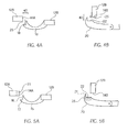
- Figures 5a and 5b show another embodiment where the radiation absorbing dye 25 is incorporated into one of the lens 12, the rimless supporting structures 16, 20, or both.
- the lens edge 14 or rimless supporting structures 16, 20 that are within connection region 40 automatically contain the radiation absorbing dye 25 required for the fusing of the two parts together. It is understood that the radiation absorbing dye 25 will not be visible to the naked eye when incorporated into the respective parts. In this embodiment, the exposure from the radiation source must take place through the part that does not contain the radiation absorbing dye 25.
- FIGS 6a and 6b show another embodiment where the rimless support structures 16 and 20 are designed such that the respective surfaces 18 and 22 engage only the lens edge 14a and 14b, respectively.
- the bridge 16 includes portions 17 that go beyond the lens edge and onto the lens surface, while the temple arm 20 include a similar portion 21. It is to be understood that the actual configuration of the bridge 16 and temple arm 20 and corresponding surfaces 18 and 22 may be changed without departing form the spirit of the present invention.
- the radiation absorbing dye 25 may be interposed as a layer on either the rimless support structure 16, 20 or the lens edge 14a and 14b as shown and described in the embodiment of Figures 4a and 4b, or may be incorporated into the respective parts as shown and described in the embodiment of Figures 5a and 5b.
- FIG. 7 shows an example of a temple arm 20 according to one possible configuration.
- temple arm 20 includes tabs 30 that are adapted to engage the edge 14b of the lens 12b.
- tabs 30 are preferably transmissive of the wavelengths of the radiation source used to irradiate the dye 25.
- the radiation absorbing dye can be interposed between the two part in any one of the previously discussed embodiments, and the radiation source can irradiate the radiation absorbing dye through the transmissive tabs 30, thereby further facilitating the manufacturing process.
- the configuration, placement, size or other aspects of tabs 30 may be altered without departing from the spirit of the invention.
- the tabs may be manufactured with a profiled surface extending in the circumferential direction. In preparing the lenses at the lab, a portion of the periphery is trimmed to mate to the profiled surface. Once welded, the tab and the lens form an integral supporting assembly that substantially avoids optical interference with the lens.
Abstract
Description
- The present invention relates to rimless spectacles. More particularly, it relates to rimless spectacles and a method of manufacturing the same using laser welding techniques.
- There has been an ongoing trend in the eyeglass industry to reduce and ideally eliminate the means for retaining the eyeglass lenses on the wearer's face. Originally, and still today, eyeglasses are manufactured using complete frames. These frames would encompass the entire circumferential edge of the lens and thereby enable the connection of temple arms and a bridge to the lens frame structure.
- After the original eyeglass frames, other versions such as partial frame or wire frame assemblies were introduced. The wire frame embodiment was such that the lenses are circumferentially entirely encompassed by very thin, small wires that attach to the temple arm portions. The wire frames provide an aesthetically pleasing appearance by substantially eliminating the visible frame from the eyeglass construction, and allowing the lens itself to define the shape of the eyeglasses. It is this aesthetic appearance that has brought on the most recent trend of rimless spectacles. In any of the above cases, the lenses must be edged before they can be inserted into hard or wire frames. This edging is required in order to facilitate the fabrication of the glasses.
- Rimless spectacles are directed at providing the least amount of hardware between the bridge, temple arms and the lenses. An example of rimless spectacles can be seen in U.S. Patent No. 2,004,005. As shown and described, rimless spectacles require the drilling of holes through the lenses for the purpose of mounting the bridge and temple arms with screws or other hardware.
- International Patent Application No. PCT/DK87/00008 discloses a Lens Holding Means for Glasses, particularly for Rimless Glasses. The bridge and temple arms are fastened to the lenses by means of holding portions that are received in holes or recesses in the lenses themselves.
- The manufacturing of rimless spectacles is time and labor intensive, as it requires the precise drilling of holes through the lenses and subsequent mounting of the temple arms and bridge to physically construct the rimless spectacles. This labor intensive process is performed after the lenses have been cut for the wearer's prescription and to the preferred shaped.
- It is therefore desirable to provide a rimless spectacle that eliminates the need for drilling holes in the lenses and which can be manufactured without requiring labor intensive processes.
- It is therefore an object of the present invention to provide a rimless spectacles that overcomes the shortfalls of the prior art and eliminates the need for additional hardware to mount the rimless supporting structures of the bridge and temple arms.
- It is another object of the invention to provide a method for manufacturing rimless spectacles that eliminates the need for drilling holes in the lenses to mount the supporting structures of the bridge and temple arms.
- It is yet another object of the invention to provide a method for manufacturing rimless spectacles that uses laser welding and specialized laser wavelength absorbing materials to attach the temple arms and bridge to the respective lenses.
- These and other objects are achieved in accordance with an embodiment of the invention wherein the method for manufacturing rimless spectacles includes the steps of providing a connection region between the lens and the rimless supporting structure wherein the connection region includes a radiation absorbing dye having a predetermined wavelength absorbing band, and exposing the radiation absorbing dye to a source of radiation operating at a wavelength within the predetermined wavelength band of the radiation absorbing dye.
- According to another embodiment of the invention, the method of manufacturing rimless spectacles includes the steps of providing a connection region between an edge of the lens and the rimless supporting structure where the connection region includes a radiation absorbing dye having a predetermined wavelength absorbing band, and exposing the radiation absorbing dye to a source of radiation operating at a wavelength within the predetermined wavelength absorbing band.
- In accordance with various embodiments of the invention, the radiation absorbing dye may be disposed in the connection region by applying the same to an external surface of the lens and/or the rimless structure at the point of contact between the two parts. The radiation dye may also be incorporated into the lens and/or the rimless supporting structures during the manufacturing of the same.
- Other objects and features of the present invention will become apparent from the following detailed description considered in conjunction with the accompanying drawings. It is to be understood, however, that the drawings are designed solely for purposes of illustration and not as a definition of the limits of the invention, for which reference should be made to the appended claims. It should be further understood that the drawings are not necessarily drawn to scale and that, unless otherwise indicated, they are merely intended to conceptually illustrate the structures and procedures described herein.
- In the drawings wherein like reference numeral denote similar components throughout the views:
- Figure 1 is perspective view of the rimless spectacles according to an embodiment of the invention;
- Figure 2 is an enlarged perspective view of the rimless spectacle bridge according to an embodiment of the invention;
- Figure 3 is an enlarged perspective view of the rimless spectacle temple arm according to an embodiment of the invention;
- Figures 4a is a schematic representation of the method of manufacturing the rimless spectacles according to a first embodiment of the invention
- Figure 4b is a schematic representation of the method of manufacturing the rimless spectacles according to a second embodiment of the invention;
- Figure 5a is a schematic representation of the method of manufacturing the rimless spectacles according to a third embodiment of the invention;
- Figures 5b is a schematic representation of the method of manufacturing the rimless spectacles according to a fourth embodiment of the invention;
- Figures 6a and 6b are schematic representations of the method of manufacturing the rimless spectacles according to another embodiment of the invention; and
- Figure 7 is a plan view of a temple arm according to another embodiment of the invention.
-
- Referring to Figures 1-3, there is shown the
rimless spectacles 10 according to an embodiment of the invention.Rimless spectacles 10 include lenses 12a and 12b that are plastic and preferably one of polycarbonate, CR-39 lenses or castable thermosetting optical resins (e.g., cast acrylic). The materials usable by the present invention are those materials that include as a primary characteristic the ability to be laser welded. The lenses 12a and 12b each have respective edges 14a and 14b that are in contact with the rimless support structures. In this application, the phrase "rimless support structures" refers to either thebridge 16, thetemple arms 20, or both. - In accordance with the present invention, the
bridge 16 andtemple arms 20 are connected to the edges 14a and 14b of the respective lenses without the use of hardware or requiring drilling into the lens to support such hardware. Thebridge 16 includes opposing surfaces 18a (not shown) and 18b that physically contact the edges 14a and 14b of the lenses 12a and 12b, respectively. Thetemple arm 20 includes asurface 22 that contacts the edges 14a and 14b of the lenses. - Referring to Figures 4a and 4b, a
contact region 40 is formed between thebridge 16 andtemple arms 20 and the respective lens edges 14a and 14b when they are brought together during manufacturing. Aradiation absorbing dye 25, having a known predetermined wavelength absorbing band, is disposed within theconnection region 40 between the rimless supportingstructures - When the lens edges 14a and 14b are brought into contact with the respective
rimless support structure radiation absorbing dye 25 is exposed to source of radiation operating at a wavelength within the known wavelength absorbing band. This exposure causes thedye 25 to decompose entirely in an exothermic reaction, that when complete, not only results in the fusing of the lens with the rimless support structure, but also results in the complete disappearance of thedye 25 when viewed by the visible eye. Those of skill in the art will recognize that the exposure to the radiation source will take place through the lens 12 orrimless support structures dye 25, and the transmissiveness of the part through which the radiation must pass to irradiate the dye. - According to this embodiment, the
radiation absorbing dye 25 may be applied to one of the lens edge surfaces 14a, 14b or thesurfaces bridge 16, andtemple arms 20, respectively. - Due to the prescriptive and ultra cosmetic nature of rimless spectacles, it is required that the
radiation absorbing dye 25 have a significantly higher decomposition efficiency than other known dyes, such as, for example, carbon black. This requirement for higher efficiency is due, in part, to the potential for interference with the optics of the prescriptive lenses. The increased efficiency of the radiation absorbing dye lowers the required concentration level, and thereby reduces the amount of radiation absorbing dye required to fuse the parts together as disclosed herein. The lower concentration makes the dye virtually invisible upon initial application. Even if the dye is slightly visible as may occur with a narrow band visible light absorbing species, a small concentration of dye will readily decompose during welding rendering the dye virtually invisible anyway. Typically, the dyes convert visible, near infrared or infrared radiation into localized heat via vibrational relaxation, after which the dye molecule decomposes into inert, invisible by-products. - Figures 5a and 5b show another embodiment where the
radiation absorbing dye 25 is incorporated into one of the lens 12, therimless supporting structures rimless supporting structures connection region 40 automatically contain theradiation absorbing dye 25 required for the fusing of the two parts together. It is understood that theradiation absorbing dye 25 will not be visible to the naked eye when incorporated into the respective parts. In this embodiment, the exposure from the radiation source must take place through the part that does not contain theradiation absorbing dye 25. - Figures 6a and 6b show another embodiment where the
rimless support structures respective surfaces bridge 16 includesportions 17 that go beyond the lens edge and onto the lens surface, while thetemple arm 20 include asimilar portion 21. It is to be understood that the actual configuration of thebridge 16 andtemple arm 20 and correspondingsurfaces - In accordance with the embodiment of Figures 6a and 6b, the
radiation absorbing dye 25 may be interposed as a layer on either therimless support structure - Figure 7 shows an example of a
temple arm 20 according to one possible configuration. As shown,temple arm 20 includestabs 30 that are adapted to engage the edge 14b of the lens 12b. In accordance with this embodiment,tabs 30 are preferably transmissive of the wavelengths of the radiation source used to irradiate thedye 25. Through the application oftabs 30, the radiation absorbing dye can be interposed between the two part in any one of the previously discussed embodiments, and the radiation source can irradiate the radiation absorbing dye through thetransmissive tabs 30, thereby further facilitating the manufacturing process. Those of ordinary skill in the art will recognize that the configuration, placement, size or other aspects oftabs 30 may be altered without departing from the spirit of the invention. For example, the tabs may be manufactured with a profiled surface extending in the circumferential direction. In preparing the lenses at the lab, a portion of the periphery is trimmed to mate to the profiled surface. Once welded, the tab and the lens form an integral supporting assembly that substantially avoids optical interference with the lens. - While there have shown and described and pointed out fundamental novel features of the invention as applied to preferred embodiments thereof, it will be understood that various omissions and substitutions and changes in the form and details of the methods described and devices illustrated, and in their operation, may be made by those skilled in the art without departing from the spirit of the invention. For example, it is expressly intended that all combinations of those elements and/or method steps which perform substantially the same function in substantially the same way to achieve the same results are within the scope of the invention. Moreover, it should be recognized that structures and/or elements and/or method steps shown and/or described in connection with any disclosed form or embodiment of the invention may be incorporated in any other disclosed or described or suggested form or embodiment as a general matter of design choice. It is the intention, therefore, to be limited only as indicated by the scope of the claims appended hereto.
Claims (12)
- A method for manufacturing rimless spectacles having lenses and rimless supporting structures, the method comprising the steps of:providing a connection region between a lens and a rimless supporting structure, said connection region having a radiation absorbing dye having a predetermined wavelength absorbing band; andexposing the radiation absorbing dye to a source of radiation operating at a wavelength within the predetermined wavelength band of the radiation absorbing dye.
- The method according to claim 1, wherein said step of providing further comprises coating a surface on the rimless support structure within the connection region with the radiation absorbing dye, and/or coating a surface of the lens within the connection region with the radiation absorbing dye.
- The method according to claim 1, wherein said step of providing further comprises incorporating the radiation absorbing dye into the lens during manufacturing of the same, and/or incorporating the radiation absorbing dye into the rimless support structure during manufacturing of the same.
- The method according to any preceding claim, wherein the connection region comprises areas on the edges of the lens and rimless supporting structures that are in contact with each other during the step of exposing.
- The method according to any preceding claim, wherein said step of exposing fuses the lens to the rimless supporting structure in the connection region.
- A method for assembling an optically transparent, rimless supporting tab onto an ophthalmic lens comprising the steps of:providing a thermoplastic supporting tab with a profiled surface extending in a circumferential direction and coating the surface with a radiation absorbing dye that is substantially transparent in visible light following irradiation;trimming a plastic ophthalmic lens to form a periphery for mating to said coated profiled surface; andassembling the tab onto the periphery and irradiating the dye within the dye's absorption band through the tab or lens to fuse the tab onto the ophthalmic lens thereby forming an integral supporting assembly that substantially avoids optical interference with the ophthalmic lens.
- The method according to claim 6, wherein upon irradiation the dye converts absorbed radiation into localized heat via vibrational relaxation, the radiation absorbing dye preferably being selected from the group consisting of a near infrared absorbing dye and an infrared absorbing dye, and wherein the dye highly transmits all wavelengths in the visible spectrum, or the radiation absorbing dye being a narrow band visible light absorbing dye that highly transmits all wavelengths outside the narrow band.
- The method according to claim 11, wherein said dye decomposes into substantially invisible by-products following irradiation.
- A method for manufacturing rimless spectacles having plastic lenses and rimless supporting structures, the method comprising the steps of:joining the rimless supporting structure with an edge of the lens in an abutting relation; andfusing the lens and rimless support structure together at the point of contact.
- The method according to claim 9, wherein said step of joining further comprises the step of providing connection region between the edge of a lens and the rimless supporting structure, said connection region having a radiation absorbing dye having a predetermined wavelength absorbing band, said step of fusing further preferably comprising the step of exposing the radiation absorbing dye to a source of radiation operating at a wavelength within the predetermined wavelength band of the radiation absorbing dye, and wherein the connection region preferably comprises areas on the edges of the lens and rimless supporting structures that are in contact with each other during the step of fusing.
- The method according to claim 10, wherein said step of providing further comprises coating a surface on the rimless support structure within the connection region with the radiation absorbing dye and/or said step of providing further comprises coating a surface of the lens edge within the connection region with the radiation absorbing dye.
- The method according to claim 10 or claim 11, wherein said step of providing further comprises incorporating the radiation absorbing dye into the lens during manufacturing of the same and/or further comprises incorporating the radiation absorbing dye into the rimless support structure during manufacturing of the same.
Applications Claiming Priority (2)
| Application Number | Priority Date | Filing Date | Title |
|---|---|---|---|
| US966951 | 2001-09-28 | ||
| US09/966,951 US6752893B2 (en) | 2001-09-28 | 2001-09-28 | Rimless spectacles and method for making the same |
Publications (2)
| Publication Number | Publication Date |
|---|---|
| EP1298482A2 true EP1298482A2 (en) | 2003-04-02 |
| EP1298482A3 EP1298482A3 (en) | 2003-12-03 |
Family
ID=25512105
Family Applications (1)
| Application Number | Title | Priority Date | Filing Date |
|---|---|---|---|
| EP02256705A Withdrawn EP1298482A3 (en) | 2001-09-28 | 2002-09-26 | Rimless spectacles and method for making same |
Country Status (4)
| Country | Link |
|---|---|
| US (1) | US6752893B2 (en) |
| EP (1) | EP1298482A3 (en) |
| JP (1) | JP2003114406A (en) |
| CA (1) | CA2404068A1 (en) |
Cited By (1)
| Publication number | Priority date | Publication date | Assignee | Title |
|---|---|---|---|---|
| EP1472085A1 (en) * | 2002-01-15 | 2004-11-03 | Gentex Corporation | Pre-processed workpiece having a surface deposition of absorber dye rendering the workpiece weld-enabled |
Families Citing this family (19)
| Publication number | Priority date | Publication date | Assignee | Title |
|---|---|---|---|---|
| US20030113273A1 (en) * | 1996-06-17 | 2003-06-19 | Patton John S. | Methods and compositions for pulmonary delivery of insulin |
| US6290991B1 (en) | 1994-12-02 | 2001-09-18 | Quandrant Holdings Cambridge Limited | Solid dose delivery vehicle and methods of making same |
| US6565885B1 (en) | 1997-09-29 | 2003-05-20 | Inhale Therapeutic Systems, Inc. | Methods of spray drying pharmaceutical compositions |
| US20060165606A1 (en) | 1997-09-29 | 2006-07-27 | Nektar Therapeutics | Pulmonary delivery particles comprising water insoluble or crystalline active agents |
| DE19955635A1 (en) * | 1999-11-20 | 2001-05-31 | Argo Gmbh Fuer Fluidtechnik | Filtering device, for filtering hydraulic fluids, comprises filter housing containing filter element with partial filter elements |
| US8404217B2 (en) | 2000-05-10 | 2013-03-26 | Novartis Ag | Formulation for pulmonary administration of antifungal agents, and associated methods of manufacture and use |
| US7871598B1 (en) | 2000-05-10 | 2011-01-18 | Novartis Ag | Stable metal ion-lipid powdered pharmaceutical compositions for drug delivery and methods of use |
| WO2001085136A2 (en) | 2000-05-10 | 2001-11-15 | Alliance Pharmaceutical Corporation | Phospholipid-based powders for drug delivery |
| EP1341668A2 (en) * | 2000-11-10 | 2003-09-10 | Gentex Corporation | Visibly transparent dyes for through-transmission laser welding |
| JP2005514393A (en) | 2001-12-19 | 2005-05-19 | ネクター セラピューティクス | Supplying aminoglycosides to the lung |
| US6805441B1 (en) * | 2003-08-11 | 2004-10-19 | Jorg Schuster | Rimless eyewear |
| WO2007044221A2 (en) | 2005-10-06 | 2007-04-19 | Beta Frames Llc. | Eyeglasses |
| US8465150B2 (en) * | 2008-10-03 | 2013-06-18 | The Beta Group Llc | Eyeglasses |
| US7726808B1 (en) | 2009-05-20 | 2010-06-01 | Gentex Optics, Inc. | Rimless spectacle lens bore polishing method and apparatus |
| US8622541B2 (en) | 2011-09-12 | 2014-01-07 | Robert B. Zider | Eyeglass frames |
| JP6073643B2 (en) * | 2012-10-25 | 2017-02-01 | 株式会社小糸製作所 | Vehicle lamp and manufacturing method thereof |
| US8985762B2 (en) * | 2013-02-27 | 2015-03-24 | Beta Frames Llc | Eyeglass frames |
| US9787345B2 (en) * | 2014-03-31 | 2017-10-10 | Apple Inc. | Laser welding of transparent and opaque materials |
| US10200516B2 (en) | 2014-08-28 | 2019-02-05 | Apple Inc. | Interlocking ceramic and optical members |
Citations (6)
| Publication number | Priority date | Publication date | Assignee | Title |
|---|---|---|---|---|
| US3824006A (en) * | 1968-04-23 | 1974-07-16 | F Voit | Optical spectacles including adhesive bonding means between metal spectacle frames and ophthalmic lenses |
| DE3239699A1 (en) * | 1982-10-27 | 1984-05-03 | Klaus 7000 Stuttgart Hafner | Rimless spectacles |
| FR2624278A1 (en) * | 1987-12-03 | 1989-06-09 | Jeangirard Claude | Extra-flexible spectacles |
| FR2719674A1 (en) * | 1994-05-04 | 1995-11-10 | Ayache Charles | Spectacles with correction or safety lenses |
| FR2749088A1 (en) * | 1996-05-21 | 1997-11-28 | Logo | Method of attaching spectacle frame to lens |
| FR2793040A1 (en) * | 1999-04-29 | 2000-11-03 | Applic Lunetieres | Production of spectacles, where material which is analogous to material used for lenses is molded over part of frame receiving lenses before lenses are mounted in frame |
Family Cites Families (53)
| Publication number | Priority date | Publication date | Assignee | Title |
|---|---|---|---|---|
| DE162922C (en) | ||||
| US2004005A (en) | 1934-03-06 | 1935-06-04 | Michael R Mcdanal | Mounting for rimless spectacles and eyeglasses |
| NL6413441A (en) | 1964-11-19 | 1966-05-20 | ||
| US3705043A (en) | 1970-12-07 | 1972-12-05 | Dick Co Ab | Infrared absorptive jet printing ink composition |
| US4069080A (en) | 1976-06-11 | 1978-01-17 | W. R. Grace & Co. | Method and apparatus of bonding superposed sheets of polymeric material in a linear weld |
| US4156626A (en) | 1977-07-18 | 1979-05-29 | Souder James J | Method and apparatus for selectively heating discrete areas of surfaces with radiant energy |
| US4424435A (en) | 1981-09-11 | 1984-01-03 | Itek Corporation | Low expansion laser welding arrangement |
| EP0126787A1 (en) | 1983-05-26 | 1984-12-05 | Jan Tjaden | Method of laser welding and plastics optimized therefor |
| DE3576823D1 (en) | 1984-03-21 | 1990-05-03 | Ici Plc | INFRARED ABSORBER. |
| EP0159169A3 (en) | 1984-04-09 | 1987-07-01 | Toyota Jidosha Kabushiki Kaisha | A process for joining different kinds of synthetic resins |
| DE3429090A1 (en) * | 1984-08-07 | 1986-02-13 | Wilhelm St. Moritz Anger | BORDERLESS GLASSES FOR CORRECTIONAL PURPOSES |
| US4657345A (en) | 1985-03-11 | 1987-04-14 | Barnes Engineering Company | Laser shield and method of making same |
| JPS62142092A (en) | 1985-12-17 | 1987-06-25 | Honda Motor Co Ltd | Adhering method for member by laser |
| DK44986A (en) | 1986-01-30 | 1987-07-31 | Poul Joern Lindberg | IMPROVED TYPE GLASSES |
| GB8705576D0 (en) | 1987-03-10 | 1987-04-15 | Ici Plc | Substituted phthalocyanine |
| FR2624041A1 (en) | 1987-12-02 | 1989-06-09 | Otic Fischer & Porter | WELDING METHOD USING A LASER BEAM, ESPECIALLY APPLICABLE TO WELDING GLASS PARTS |
| US4906320A (en) | 1988-04-15 | 1990-03-06 | The Interlake Companies, Inc. | Apparatus for infrared sealing of plastic strap |
| US4969969A (en) | 1988-04-15 | 1990-11-13 | The Interlake Companies, Inc. | Apparatus and method for infrared sealing of plastic strap |
| US5005926A (en) | 1988-10-18 | 1991-04-09 | Barnes Engineering Company | Ballistic protective laser shield |
| US4892584A (en) | 1988-12-05 | 1990-01-09 | Eastman Kodak Company | Water soluble infrared absorbing dyes and ink-jet inks containing them |
| SE465214B (en) | 1990-01-16 | 1991-08-12 | Tetra Pak Holdings Sa | SETTLE TO HEAT PART OF CURRENT MATERIALS |
| US5279693A (en) | 1990-05-09 | 1994-01-18 | Lps Industries, Inc. | Welding thermoplastic material with a laser |
| US5093147A (en) | 1990-09-12 | 1992-03-03 | Battelle Memorial Institute | Providing intelligible markings |
| EP0483569A1 (en) | 1990-10-29 | 1992-05-06 | Fmc Corporation | Plastic welding apparatus |
| US5267959A (en) | 1991-11-29 | 1993-12-07 | Schneider, Inc. | Laser bonding of angioplasty balloon catheters |
| US5252262A (en) | 1992-02-11 | 1993-10-12 | Nestle S.A. | Method of attaching a haptic to an optic of an intraocular lens |
| JPH06298828A (en) | 1993-04-14 | 1994-10-25 | Tonen Corp | Production of propylene block copolymer |
| US5893959A (en) | 1994-03-31 | 1999-04-13 | Marquardt Gmbh | Workpiece of plastic and production process for such a workpiece |
| DE4432081A1 (en) | 1994-09-09 | 1996-03-14 | Basf Ag | Radiation welding of thermoplastics and non melting materials using laser light |
| US5646706A (en) * | 1994-12-21 | 1997-07-08 | Hoya Corporation | Spectacle lens holding structure |
| JPH08230043A (en) | 1995-02-27 | 1996-09-10 | Aisamu:Kk | Welding of synthetic resin material |
| GB9508810D0 (en) | 1995-05-01 | 1995-06-21 | Zeneca Ltd | Compounds |
| US5840147A (en) | 1995-06-07 | 1998-11-24 | Edison Welding Institute | Plastic joining method |
| US5837042A (en) | 1996-06-10 | 1998-11-17 | Videojet Systems International, Inc. | Invisible fluorescent jet ink |
| DE19602892A1 (en) | 1996-01-27 | 1997-07-31 | Weidenhammer Packungen | Process for producing winding cores from cardboard composite material, device for carrying out the method and cardboard composite material used here |
| JP3409561B2 (en) | 1996-02-19 | 2003-05-26 | 東海ゴム工業株式会社 | Method for manufacturing vehicle structure |
| GB9614659D0 (en) | 1996-07-12 | 1996-09-04 | Askin Michael | Method and apparatus to provide a welded plastic sealing strip |
| US5833743A (en) | 1996-09-10 | 1998-11-10 | Colorspan Corporation | Method of selecting an ink set of an ink jet printer |
| WO1998018871A1 (en) | 1996-10-28 | 1998-05-07 | Eastman Chemical Company | Organic solvent based ink for invisible marking/identification |
| US5897694A (en) | 1997-01-06 | 1999-04-27 | Formulabs | Methods for improving the adhesion and/or colorfastness of ink jet inks with respect to substrates applied thereto, and compositions useful therefor |
| EP0901902A3 (en) | 1997-09-12 | 1999-03-24 | Fuji Photo Film Co., Ltd. | Positive photosensitive composition for use with an infrared laser |
| US6010564A (en) | 1997-10-16 | 2000-01-04 | Videojet Systems International, Inc. | Jet ink composition |
| GB9818689D0 (en) | 1998-08-28 | 1998-10-21 | Zeneca Ltd | Compounds |
| GB9821375D0 (en) | 1998-10-01 | 1998-11-25 | Welding Inst | Welding method |
| US6149719A (en) | 1998-10-28 | 2000-11-21 | Hewlett-Packard Company | Light sensitive invisible ink compositions and methods for using the same |
| US6329635B1 (en) | 1998-10-30 | 2001-12-11 | The University Of Chicago | Methods for weld monitoring and laser heat treatment monitoring |
| US6024444A (en) | 1998-12-18 | 2000-02-15 | Luxottica Leasing S.P.A. | Eyewear lens retention apparatus and method |
| US6248161B1 (en) | 1999-01-11 | 2001-06-19 | Hewlett-Packard Company | Preparation of permanent color inks from water-soluble colorants using specific phosphonium salts |
| US6136079A (en) | 1999-04-30 | 2000-10-24 | Eastman Kodak Company | Dye for ink jet ink |
| US6174356B1 (en) | 1999-05-06 | 2001-01-16 | Eastman Kodak Company | Dye for ink jet ink |
| US6220673B1 (en) | 1999-07-12 | 2001-04-24 | Colgate-Palmolive Company | Laser joining toothbrush heads to handles |
| GB9917593D0 (en) | 1999-07-28 | 1999-09-29 | Avecia Ltd | Compound, composition, process and use |
| US6199981B1 (en) * | 2000-01-27 | 2001-03-13 | David Yinkai Chao | Method for securing spectacle members together |
-
2001
- 2001-09-28 US US09/966,951 patent/US6752893B2/en not_active Expired - Fee Related
-
2002
- 2002-09-18 CA CA002404068A patent/CA2404068A1/en not_active Abandoned
- 2002-09-26 EP EP02256705A patent/EP1298482A3/en not_active Withdrawn
- 2002-09-27 JP JP2002283357A patent/JP2003114406A/en active Pending
Patent Citations (6)
| Publication number | Priority date | Publication date | Assignee | Title |
|---|---|---|---|---|
| US3824006A (en) * | 1968-04-23 | 1974-07-16 | F Voit | Optical spectacles including adhesive bonding means between metal spectacle frames and ophthalmic lenses |
| DE3239699A1 (en) * | 1982-10-27 | 1984-05-03 | Klaus 7000 Stuttgart Hafner | Rimless spectacles |
| FR2624278A1 (en) * | 1987-12-03 | 1989-06-09 | Jeangirard Claude | Extra-flexible spectacles |
| FR2719674A1 (en) * | 1994-05-04 | 1995-11-10 | Ayache Charles | Spectacles with correction or safety lenses |
| FR2749088A1 (en) * | 1996-05-21 | 1997-11-28 | Logo | Method of attaching spectacle frame to lens |
| FR2793040A1 (en) * | 1999-04-29 | 2000-11-03 | Applic Lunetieres | Production of spectacles, where material which is analogous to material used for lenses is molded over part of frame receiving lenses before lenses are mounted in frame |
Cited By (2)
| Publication number | Priority date | Publication date | Assignee | Title |
|---|---|---|---|---|
| EP1472085A1 (en) * | 2002-01-15 | 2004-11-03 | Gentex Corporation | Pre-processed workpiece having a surface deposition of absorber dye rendering the workpiece weld-enabled |
| EP1472085A4 (en) * | 2002-01-15 | 2008-08-13 | Gentex Corp | Pre-processed workpiece having a surface deposition of absorber dye rendering the workpiece weld-enabled |
Also Published As
| Publication number | Publication date |
|---|---|
| US6752893B2 (en) | 2004-06-22 |
| EP1298482A3 (en) | 2003-12-03 |
| JP2003114406A (en) | 2003-04-18 |
| US20030062117A1 (en) | 2003-04-03 |
| CA2404068A1 (en) | 2003-03-28 |
Similar Documents
| Publication | Publication Date | Title |
|---|---|---|
| US6752893B2 (en) | Rimless spectacles and method for making the same | |
| US7090349B2 (en) | Single vision lenses | |
| US6334681B1 (en) | Lenses and spectacles bearing lenses | |
| US9897886B2 (en) | Lens for displaying a virtual image | |
| JP5759484B2 (en) | Lens manufacturing method for providing an optical display | |
| WO2006070830A1 (en) | Protection glasses-use lens | |
| KR102087621B1 (en) | Eyewear with detachable lens | |
| KR20240013133A (en) | Ophthalmic lenses for reducing myopia progression and laser-based methods for forming them | |
| WO2002059684A3 (en) | Activity-specific optical filters and eyewear using such filters | |
| CN111417892B (en) | Eyewear with variable transmission lenses | |
| US5387950A (en) | Prescription eyewear made from non-prescription lens shield material | |
| KR20030042953A (en) | Spectacle Lens for Correcting Sight | |
| US7278738B2 (en) | Eyeglass lens with non-uniform coatings | |
| JP2003021813A (en) | Ornamental spectacle member | |
| WO1997016761A1 (en) | Magnetic eyewear system | |
| KR102585805B1 (en) | Corrective lenses and shields of a single structure and methods | |
| RU2128355C1 (en) | Lenses for holographic spectacles | |
| US20220308367A1 (en) | Eyewear having an anti reflective portion | |
| GB2277602A (en) | Opthalmic graduated photochromic lens | |
| KR20230160483A (en) | Eyewear | |
| GB2178864A (en) | Spectacle front frames | |
| KR20230020395A (en) | Electrochromic lens comprising a wafer having a peripheral shoulder | |
| WO2016126742A1 (en) | Eyeglass assemblies | |
| EP3629077A1 (en) | Improved method for making a component of spectacle frame | |
| AU727930B2 (en) | Improved single vision lenses |
Legal Events
| Date | Code | Title | Description |
|---|---|---|---|
| PUAI | Public reference made under article 153(3) epc to a published international application that has entered the european phase |
Free format text: ORIGINAL CODE: 0009012 |
|
| AK | Designated contracting states |
Kind code of ref document: A2 Designated state(s): AT BE BG CH CY CZ DE DK EE ES FI FR GB GR IE IT LI LU MC NL PT SE SK TR Designated state(s): AT BE BG CH CY CZ DE DK EE ES FI FR GB GR IE IT LI LU MC NL PT SE SK TR |
|
| AX | Request for extension of the european patent |
Extension state: AL LT LV MK RO SI |
|
| PUAL | Search report despatched |
Free format text: ORIGINAL CODE: 0009013 |
|
| AK | Designated contracting states |
Kind code of ref document: A3 Designated state(s): AT BE BG CH CY CZ DE DK EE ES FI FR GB GR IE IT LI LU MC NL PT SE SK TR |
|
| AX | Request for extension of the european patent |
Extension state: AL LT LV MK RO SI |
|
| 17P | Request for examination filed |
Effective date: 20040130 |
|
| AKX | Designation fees paid |
Designated state(s): AT BE BG CH CY CZ DE DK EE ES FI FR GB GR IE IT LI LU MC NL PT SE SK TR |
|
| STAA | Information on the status of an ep patent application or granted ep patent |
Free format text: STATUS: THE APPLICATION IS DEEMED TO BE WITHDRAWN |
|
| 18D | Application deemed to be withdrawn |
Effective date: 20080401 |