EP1298311A1 - Water-cooled exhaust gas recirculating device - Google Patents
Water-cooled exhaust gas recirculating device Download PDFInfo
- Publication number
- EP1298311A1 EP1298311A1 EP00937321A EP00937321A EP1298311A1 EP 1298311 A1 EP1298311 A1 EP 1298311A1 EP 00937321 A EP00937321 A EP 00937321A EP 00937321 A EP00937321 A EP 00937321A EP 1298311 A1 EP1298311 A1 EP 1298311A1
- Authority
- EP
- European Patent Office
- Prior art keywords
- cooling water
- exhaust gas
- water
- hole
- circulation
- Prior art date
- Legal status (The legal status is an assumption and is not a legal conclusion. Google has not performed a legal analysis and makes no representation as to the accuracy of the status listed.)
- Withdrawn
Links
Images


Classifications
-
- F—MECHANICAL ENGINEERING; LIGHTING; HEATING; WEAPONS; BLASTING
- F02—COMBUSTION ENGINES; HOT-GAS OR COMBUSTION-PRODUCT ENGINE PLANTS
- F02M—SUPPLYING COMBUSTION ENGINES IN GENERAL WITH COMBUSTIBLE MIXTURES OR CONSTITUENTS THEREOF
- F02M26/00—Engine-pertinent apparatus for adding exhaust gases to combustion-air, main fuel or fuel-air mixture, e.g. by exhaust gas recirculation [EGR] systems
- F02M26/65—Constructional details of EGR valves
- F02M26/72—Housings
- F02M26/73—Housings with means for heating or cooling the EGR valve
-
- F—MECHANICAL ENGINEERING; LIGHTING; HEATING; WEAPONS; BLASTING
- F02—COMBUSTION ENGINES; HOT-GAS OR COMBUSTION-PRODUCT ENGINE PLANTS
- F02M—SUPPLYING COMBUSTION ENGINES IN GENERAL WITH COMBUSTIBLE MIXTURES OR CONSTITUENTS THEREOF
- F02M26/00—Engine-pertinent apparatus for adding exhaust gases to combustion-air, main fuel or fuel-air mixture, e.g. by exhaust gas recirculation [EGR] systems
- F02M26/13—Arrangement or layout of EGR passages, e.g. in relation to specific engine parts or for incorporation of accessories
- F02M26/22—Arrangement or layout of EGR passages, e.g. in relation to specific engine parts or for incorporation of accessories with coolers in the recirculation passage
- F02M26/29—Constructional details of the coolers, e.g. pipes, plates, ribs, insulation or materials
- F02M26/32—Liquid-cooled heat exchangers
-
- F—MECHANICAL ENGINEERING; LIGHTING; HEATING; WEAPONS; BLASTING
- F02—COMBUSTION ENGINES; HOT-GAS OR COMBUSTION-PRODUCT ENGINE PLANTS
- F02M—SUPPLYING COMBUSTION ENGINES IN GENERAL WITH COMBUSTIBLE MIXTURES OR CONSTITUENTS THEREOF
- F02M26/00—Engine-pertinent apparatus for adding exhaust gases to combustion-air, main fuel or fuel-air mixture, e.g. by exhaust gas recirculation [EGR] systems
- F02M26/52—Systems for actuating EGR valves
- F02M26/53—Systems for actuating EGR valves using electric actuators, e.g. solenoids
-
- F—MECHANICAL ENGINEERING; LIGHTING; HEATING; WEAPONS; BLASTING
- F01—MACHINES OR ENGINES IN GENERAL; ENGINE PLANTS IN GENERAL; STEAM ENGINES
- F01P—COOLING OF MACHINES OR ENGINES IN GENERAL; COOLING OF INTERNAL-COMBUSTION ENGINES
- F01P11/00—Component parts, details, or accessories not provided for in, or of interest apart from, groups F01P1/00 - F01P9/00
- F01P11/02—Liquid-coolant filling, overflow, venting, or draining devices
- F01P11/0276—Draining or purging
Definitions
- the invention relates to a water-cooled exhaust gas re-circulation device disposed at an exhaust gas re-circulation passage of an internal combustion engine such as engines.
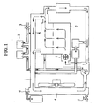
- FIG. 1 illustrates a schematic representation of the whole of a conventional cooling water re-circulation passage arranged at the internal combustion engine.
- FIG. 2 is a front view of a water-cooled exhaust gas re-circulation device arranged at the conventional cooling water re-circulation of FIG. 1.
- FIG. 3 is a cross sectional view taken along lines III-III of FIG. 2.
- FIG. 4 is a cross sectional view of a hole formed at a part of the cooling water re-circulation passage within the water-cooled exhaust gas re-circulation device during a due casting.
- a reference numeral 1 denotes a cooling water re-circulation passage
- a reference numeral 2 denotes a water-cooled exhaust gas re-circulation device arranged at the cooling water re-circulation passage 1.
- a reference numeral 3 denotes a drain bolt independent of another components arranged at the cooling water re-circulation passage 1 close to a cylinder block and constituting a hole communicating the cooling water re-circulation passage 1 and outside air.
- a reference numeral 4 denotes a radiator preventing the cooling water re-circulated in the cooling water re-circulation passage 1 from increasing the temperature.
- a reference numeral 5 denotes a drain cock acting as an outlet of the cooling water when the cooling water is changed to new one.
- a reference numeral 6 denotes a radiator cap controlling an internal pressure of the cooling water re-circulation passage 1.
- the radiator cap 6 constitutes an air hole, which is close to the radiator when the cooling water is changed to new one, and an inlet of the cooling water when the cooling water is supplied to the cooling water re-circulation passage 1.
- a reference numeral 7 denotes a cylinder block constituting an external engine.
- a reference numeral 8 denotes a water pump arranged in the cooling water re-circulation passage 1 and supplying the cooling water to the cylinder block 7 of the engine in order to re-circulate it in the cooling water re-circulation passage 1.
- the water-cooled exhaust gas re-circulation device 2 includes a valve housing 10 including an exhaust gas re-circulation valve (not shown) and a motor main body 11 including a motor driving the exhaust gas re-circulation valve as shown in FIG. 2 and FIG. 3.
- the motor main body 11 is affixed to the valve housing 10 with screws 12.
- a reference numeral 13 denotes a terminal supplying electric power to the motor (not shown) arranged in the motor main body 11.
- Reference numerals 14 and 15 denote inlet and outlet of an exhaust gas re-circulation passage, which is opened and closed due to the exhaust gas re-circulation valve.
- a reference numeral 16 denotes a nipple guiding the cooling water from the cooling water re-circulation passage 1, which is close to the engine, to the cooling water re-circulation passage 1 within the water-cooled exhaust gas re-circulation device 2.
- the drain cock 5 arranged at a lower section of the radiator 4 is used as a discharge port of the cooling water and the radiator cap 6 mounted on an upper section of the radiator 4 is used as the air hole.
- the temperature of the cooling water is adequately reduced after stopping the engine.
- the radiator cap 5 is opened to introduce air to the cooling water re-circulation passage 1.
- the drain cock 5 is then opened to discharge the cooling water.
- the drain bolt 3 acting as the air hole close to the engine is opened and the cooling water close to the engine is conveyed toward the radiator to discharge it to outside through the drain cock 5.
- the required amount of the cooling water is supplied to the passage 1 through the radiator cap 6 after the drain cock 5 is closed.
- the drain bolt 3 acts as an air hole discharging smoothly air in the cooling water re-circulation passage 1 to outside.
- the conventional water-cooled exhaust gas re-circulation device has a complex layout to produce a redundant space and parts.
- An object of the invention is to provide a water-cooled exhaust gas re-circulation device allowing simplifying the layout of the cooling water re-circulation passage and reducing costs due to reducing a component count and saving a space.
- a water-cooled exhaust gas re-circulation device is characterized in that a hole open/close mechanism allowing communication with outside air is arranged at a cooling water re-circulation passage cooling an exhaust gas re-circulation valve.
- a hole open/close mechanism allowing communication with outside air is arranged at a cooling water re-circulation passage cooling an exhaust gas re-circulation valve.
- the water-cooled exhaust gas re-circulation device is characterized in that the hole-open/close mechanism is a drain bolt. In this way, even if an interference substance is close to the drain bolt, it is possible to ensure an air hole with respect to the cooling water re-circulation passage without removing the drain bolt.
- the water-cooled exhaust gas re-circulation device is characterized in that the hole-open/close mechanism is arranged at a stopper stopping up a hole formed during manufacturing the cooling water re-circulation passage. In this way, it is not necessary to form an exclusive hole at the cooling water re-circulation passage in order to install the hole-open/close mechanism. It is possible to allow reducing costs and saving a space as compared with a case of forming the exclusive hole.
- FIG. 5 is a front view of a water-cooled exhaust gas re-circulation device as embodiment 1 according to the invention.
- FIG. 6 is a plan view of the water-cooled exhaust gas re-circulation device of FIG. 5.
- FIG. 7 is a side view of the water-cooled exhaust gas re-circulation device of FIG. 5.
- FIG. 8 is a cross sectional view taken along lines VIII-VIII of FIG. 5.
- FIG. 9A is an enlarged plan view of a drain bolt of FIG. 8.
- FIG. 9B is a plan view of a state of loosening the drain bolt of FIG. 9A inserted in a hole.
- FIG. 10 illustrates a schematic representation of the whole of a cooling water re-circulation passage arranged at the internal combustion engine providing with the water-cooled exhaust gas re-circulation device as embodiment 1 according to the invention.
- Components of the embodiment 1 common to the conventional components are denoted by the same reference numerals and further description will be omitted.
- a reference numeral 20 denotes a drain bolt, which is inserted rotationally into the hole 17, which is formed at the cooling water re-circulation passage 1 in a manufacturing step such as die casting and so on, through a packing 21.
- the drain bolt 20 includes a head section 20a having a major diameter, a leg section 20b having an outer diameter corresponding to an inner diameter of the hole 17, a threaded section 20c formed at an outer peripheral face of the leg section 20b, and a pair of notches 20d formed at a lower section of the leg section 20b in a chord or lateral direction as shown in FIG. 9A and FIG. 9B.
- the temperature of the cooling water is adequately reduced after stopping the engine.
- the radiator cap 5 With the state, while adjusting an internal pressure of the cooling water re-circulation passage 1 due to open/close of the radiator cap 6, the radiator cap 5 is opened to introduce air to the cooling water re-circulation passage 1.
- the drain cock 5 is then opened to discharge the cooling water.
- the drain bolt 20, which acts as the air hole close to the engine and is integrated with the water-cooled exhaust gas device, is rotated to loosen it. In this way, air is introduced to the cooling water re-circulation passage 1 through a gap defined between the notches 20d of the drain bolt 20 and an inner peripheral wall of the hole 17.
- the cooling water close to the engine is then conveyed toward the radiator to discharge it to outside through the drain cock 5.
- the required amount of the cooling water is supplied to the passage 1 through the radiator cap 6 after the drain cock 5 is closed.
- the drain bolt 20 being integrated with the water-cooled exhaust gas re-circulation device is loosened.
- the drain bolt 20 acts as an air hole discharging smoothly air in the cooling water re-circulation passage 1 to outside.
- the air communication through the drain bolt 20 can be performed only by opening and closing the drain bolt 20. Even if an interference substance X is close to the drain bolt 20 as shown in FIG. 9B, it is possible to supply air to the cooling water re-circulation passage 1 or to discharge air therefrom through a slight space close to the head section 20a of the drain bolt 20 using the drain bolt 20 without removing it.
- the drain bolt 20 acting as the hole-open/close mechanism is integrated with the cooling water re-circulation passage 1 to result in removing the conventional drain bolt 3 independent of the exhaust gas re-circulation valve. In this way, it is possible to allow saving a space, simplifying the structure and reducing a component count.
- the drain bolt 20 acting as the hole-open/close mechanism is arranged in the hole 17 formed at the cooling water re-circulation passage 1 due to the die casting. In this way, it is not necessary to form an exclusive hole at the cooling water re-circulation passage 1 in order to install the hole-open/close mechanism. It is possible to allow reducing costs and saving a space as compared with a case of forming the exclusive hole.
- the drain bolt 20 acting as the hole-open/close mechanism is arranged in the hole 17 formed at the cooling water re-circulation passage 1 due to the die casting.
- the drain bolt 20 may be arranged at the cooling water re-circulation passage 1 other than the hole 17 to allow communicating with outside.
- the drain bolt 20 is used as the hole-open/close mechanism.
- the invention is not limited to this embodiment.
- the drain bolt acting as the hole-open/close mechanism is integrated with the cooling water re-circulation passage to result in removing the conventional drain bolt independent of the exhaust gas re-circulation valve. In this way, it is possible to allow saving a space, simplifying the structure and reducing a component count.
Landscapes
- Engineering & Computer Science (AREA)
- Chemical & Material Sciences (AREA)
- Combustion & Propulsion (AREA)
- Mechanical Engineering (AREA)
- General Engineering & Computer Science (AREA)
- Exhaust-Gas Circulating Devices (AREA)
- Exhaust Silencers (AREA)
Abstract
Description
First, as shown in FIG. 1, to discharge the cooling water to change it to new one, the temperature of the cooling water is adequately reduced after stopping the engine. With the state, while adjusting an internal pressure of the cooling
First, as shown in FIG. 1, to discharge the cooling water to change it to new one, the temperature of the cooling water is adequately reduced after stopping the engine. With the state, while adjusting an internal pressure of the cooling
Claims (3)
- A water-cooled exhaust gas re-circulation device characterized in that a hole-open/close mechanism allowing communication with outside air is arranged at a cooling water re-circulation passage cooling an exhaust gas re-circulation valve.
- A water-cooled exhaust gas re-circulation device according to Claim 1, wherein the hole-open/close mechanism is a drain bolt.
- A water-cooled exhaust gas re-circulation device according to Claim 1, wherein the hole-open/close mechanism is arranged at a stopper stopping up a hole formed during manufacturing the cooling water re-circulation passage.
Applications Claiming Priority (1)
| Application Number | Priority Date | Filing Date | Title |
|---|---|---|---|
| PCT/JP2000/004017 WO2001098647A1 (en) | 2000-06-20 | 2000-06-20 | Water-cooled exhaust gas recirculating device |
Publications (2)
| Publication Number | Publication Date |
|---|---|
| EP1298311A1 true EP1298311A1 (en) | 2003-04-02 |
| EP1298311A4 EP1298311A4 (en) | 2004-04-21 |
Family
ID=11736163
Family Applications (1)
| Application Number | Title | Priority Date | Filing Date |
|---|---|---|---|
| EP00937321A Withdrawn EP1298311A4 (en) | 2000-06-20 | 2000-06-20 | DEVICE FOR RECYCLING WATER COOLED EXHAUST GASES |
Country Status (5)
| Country | Link |
|---|---|
| US (1) | US6662789B1 (en) |
| EP (1) | EP1298311A4 (en) |
| KR (1) | KR20020023420A (en) |
| CN (1) | CN1167872C (en) |
| WO (1) | WO2001098647A1 (en) |
Families Citing this family (9)
| Publication number | Priority date | Publication date | Assignee | Title |
|---|---|---|---|---|
| JP4323333B2 (en) * | 2004-01-19 | 2009-09-02 | 株式会社マーレ フィルターシステムズ | Exhaust gas recirculation device for internal combustion engine |
| US7254947B2 (en) * | 2005-06-10 | 2007-08-14 | Deere & Company | Vehicle cooling system |
| JP4814188B2 (en) * | 2007-09-19 | 2011-11-16 | 株式会社クボタ | engine |
| JP4729548B2 (en) * | 2007-09-19 | 2011-07-20 | 株式会社クボタ | engine |
| US7942138B1 (en) | 2008-03-24 | 2011-05-17 | Brunswick Corporation | Outboard motor with exhaust gas recirculation cooling |
| US7625257B1 (en) | 2008-03-24 | 2009-12-01 | Brunswick Corporation | Exhaust gas recirculation cooling system for an engine of an outboard motor |
| US8132407B2 (en) * | 2008-04-03 | 2012-03-13 | GM Global Technology Operations LLC | Modular exhaust gas recirculation cooling for internal combustion engines |
| FR3068432A1 (en) * | 2017-06-29 | 2019-01-04 | Valeo Systemes De Controle Moteur | ASSEMBLY COMPRISING A RECEPTACLE AND A GAS FLOW CONTROL VALVE FOR ASSEMBLY |
| JP7068219B2 (en) * | 2019-03-18 | 2022-05-16 | トヨタ自動車株式会社 | Exhaust gas recirculation valve warm-up device |
Family Cites Families (17)
| Publication number | Priority date | Publication date | Assignee | Title |
|---|---|---|---|---|
| US4134377A (en) * | 1977-09-29 | 1979-01-16 | Borg-Warner Corporation | Exhaust gas recirculation control valve and heat exchanger |
| JPS57191442A (en) * | 1981-05-20 | 1982-11-25 | Honda Motor Co Ltd | Exhaust gas recirculation control device for internal combustion engine |
| JPS62108560U (en) * | 1985-12-26 | 1987-07-10 | ||
| JPH0354271U (en) * | 1989-10-02 | 1991-05-24 | ||
| JP2713803B2 (en) * | 1990-07-03 | 1998-02-16 | 日野自動車工業株式会社 | Exhaust gas recirculation system using water-cooled EGR valve |
| JPH0666209A (en) * | 1992-08-14 | 1994-03-08 | Taiho Kogyo Co Ltd | Exhaust gas recirculating device |
| JPH06229329A (en) | 1993-01-30 | 1994-08-16 | Suzuki Motor Corp | Cooling water circulating device of egr valve |
| JPH0814114A (en) * | 1994-06-28 | 1996-01-16 | Unisia Jecs Corp | Flow control valve for exhaust gas recirculation control device |
| DE19730998C2 (en) * | 1996-07-19 | 2001-10-31 | Hitachi Ltd | Engine operated flow control valve and exhaust gas recirculation control valve for internal combustion engines |
| JP3430815B2 (en) * | 1996-09-18 | 2003-07-28 | 日産自動車株式会社 | Exhaust gas recirculation device for internal combustion engine |
| US5970960A (en) * | 1996-09-18 | 1999-10-26 | Nissan Motor Co., Ltd. | Exhaust gas recirculation system of internal combustion engine |
| JPH11141411A (en) * | 1997-10-31 | 1999-05-25 | Mitsubishi Motors Corp | EGR valve cooling device |
| DE19750588B4 (en) * | 1997-11-17 | 2016-10-13 | MAHLE Behr GmbH & Co. KG | Device for exhaust gas recirculation for an internal combustion engine |
| WO1999061775A1 (en) * | 1998-05-27 | 1999-12-02 | Mitsubishi Denki Kabushiki Kaisha | Exhaust gas reflux valve |
| US6237547B1 (en) * | 1998-09-10 | 2001-05-29 | Yamaha Hatsudoki Kabushiki Kaisha | Engine cooling arrangement |
| DE19929956C5 (en) * | 1999-06-29 | 2007-02-22 | Daimlerchrysler Ag | Exhaust gas recirculation valve |
| US6505614B1 (en) * | 1999-10-14 | 2003-01-14 | Siemens Canada Limited | Connection formed by engagement of a tube and a valve surface |
-
2000
- 2000-06-20 CN CNB008116210A patent/CN1167872C/en not_active Expired - Fee Related
- 2000-06-20 EP EP00937321A patent/EP1298311A4/en not_active Withdrawn
- 2000-06-20 WO PCT/JP2000/004017 patent/WO2001098647A1/en not_active Ceased
- 2000-06-20 KR KR1020027001966A patent/KR20020023420A/en not_active Ceased
- 2000-06-20 US US10/030,696 patent/US6662789B1/en not_active Expired - Lifetime
Also Published As
| Publication number | Publication date |
|---|---|
| KR20020023420A (en) | 2002-03-28 |
| EP1298311A4 (en) | 2004-04-21 |
| WO2001098647A1 (en) | 2001-12-27 |
| CN1167872C (en) | 2004-09-22 |
| CN1370256A (en) | 2002-09-18 |
| US6662789B1 (en) | 2003-12-16 |
Similar Documents
| Publication | Publication Date | Title |
|---|---|---|
| US6662789B1 (en) | Water-cooled exhaust gas recirculating device | |
| US9062636B2 (en) | Drop-in type of exhaust gas recirculation valve, and system for attaching same | |
| US7162986B2 (en) | Cylinder head cover | |
| EP2322789B1 (en) | Automatic residual fuel vent device for carburetor | |
| US6615796B2 (en) | Multi-cylinder engine | |
| EP2057356B1 (en) | Cam cap | |
| EP1388662B1 (en) | Sohc type engine | |
| JP2006342799A (en) | Internal combustion engine | |
| US7263969B2 (en) | Idle air control apparatus in multiple throttle body | |
| JPWO2001098647A1 (en) | Water-cooled exhaust gas recirculation system | |
| JP3402148B2 (en) | Air venting device for cooling water jacket with pre-cooling air intake in slant type internal combustion engine | |
| KR100820464B1 (en) | Combustion chamber for cylinder head and inlet / | |
| KR200182403Y1 (en) | Pressure control valve combine fixed bolt and fixed bolt use engine oil filter fixed structure | |
| US20250035030A1 (en) | Method for producing an internal combustion engine comprising a precombustion chamber | |
| JP2004169591A (en) | Lubricating oil passage structure in cylinder block of internal combustion engine | |
| KR20160103735A (en) | Clean engine easy to disassemble any cylinder head individually | |
| JP2008075507A (en) | Water-cooled multi-cylinder engine | |
| KR0119024Y1 (en) | Motor | |
| JPH1136863A (en) | Cooling mechanism of v-shape engine | |
| JP2551543Y2 (en) | Pressure oil supply device | |
| KR200198437Y1 (en) | Pump assembly for inplanter | |
| JPH06137229A (en) | Fuel supply device in fuel injection type internal combustion engine | |
| JPH07259803A (en) | Lifting valve | |
| KR20010059847A (en) | Nipple for pouring oil in engine cylinder | |
| JP2005133709A (en) | Variable air intake module of engine |
Legal Events
| Date | Code | Title | Description |
|---|---|---|---|
| PUAI | Public reference made under article 153(3) epc to a published international application that has entered the european phase |
Free format text: ORIGINAL CODE: 0009012 |
|
| 17P | Request for examination filed |
Effective date: 20020219 |
|
| AK | Designated contracting states |
Kind code of ref document: A1 Designated state(s): AT BE CH CY DE DK ES FI FR GB GR IE IT LI LU MC NL PT SE Designated state(s): AT BE CH CY DE DK ES FI FR GB GR IE IT LI LU MC NL PT SE |
|
| A4 | Supplementary search report drawn up and despatched |
Effective date: 20040309 |
|
| RBV | Designated contracting states (corrected) |
Designated state(s): DE FR IT |
|
| RAP1 | Party data changed (applicant data changed or rights of an application transferred) |
Owner name: MITSUBISHI DENKI KABUSHIKI KAISHA |
|
| R17P | Request for examination filed (corrected) |
Effective date: 20020219 |
|
| 17Q | First examination report despatched |
Effective date: 20090219 |
|
| STAA | Information on the status of an ep patent application or granted ep patent |
Free format text: STATUS: THE APPLICATION IS DEEMED TO BE WITHDRAWN |
|
| 18D | Application deemed to be withdrawn |
Effective date: 20100126 |