EP1298256A2 - Hydraulic system for suppression of vibrations of a working machine - Google Patents
Hydraulic system for suppression of vibrations of a working machine Download PDFInfo
- Publication number
- EP1298256A2 EP1298256A2 EP02256386A EP02256386A EP1298256A2 EP 1298256 A2 EP1298256 A2 EP 1298256A2 EP 02256386 A EP02256386 A EP 02256386A EP 02256386 A EP02256386 A EP 02256386A EP 1298256 A2 EP1298256 A2 EP 1298256A2
- Authority
- EP
- European Patent Office
- Prior art keywords
- valve
- rotating
- communicating valve
- pressure oil
- hydraulic
- Prior art date
- Legal status (The legal status is an assumption and is not a legal conclusion. Google has not performed a legal analysis and makes no representation as to the accuracy of the status listed.)
- Withdrawn
Links
- 230000001629 suppression Effects 0.000 title 1
- 230000007935 neutral effect Effects 0.000 claims abstract description 24
- 230000001133 acceleration Effects 0.000 claims description 15
- 239000003921 oil Substances 0.000 claims 12
- 239000010720 hydraulic oil Substances 0.000 claims 1
- 230000010355 oscillation Effects 0.000 abstract 1
- 238000010276 construction Methods 0.000 description 10
- 239000012530 fluid Substances 0.000 description 8
- 230000003111 delayed effect Effects 0.000 description 6
- 238000010586 diagram Methods 0.000 description 6
- 238000006073 displacement reaction Methods 0.000 description 1
- 238000012423 maintenance Methods 0.000 description 1
- 239000013589 supplement Substances 0.000 description 1
- 230000001131 transforming effect Effects 0.000 description 1
Images


Classifications
-
- E—FIXED CONSTRUCTIONS
- E02—HYDRAULIC ENGINEERING; FOUNDATIONS; SOIL SHIFTING
- E02F—DREDGING; SOIL-SHIFTING
- E02F9/00—Component parts of dredgers or soil-shifting machines, not restricted to one of the kinds covered by groups E02F3/00 - E02F7/00
- E02F9/20—Drives; Control devices
-
- E—FIXED CONSTRUCTIONS
- E02—HYDRAULIC ENGINEERING; FOUNDATIONS; SOIL SHIFTING
- E02F—DREDGING; SOIL-SHIFTING
- E02F9/00—Component parts of dredgers or soil-shifting machines, not restricted to one of the kinds covered by groups E02F3/00 - E02F7/00
- E02F9/20—Drives; Control devices
- E02F9/22—Hydraulic or pneumatic drives
- E02F9/2203—Arrangements for controlling the attitude of actuators, e.g. speed, floating function
- E02F9/2207—Arrangements for controlling the attitude of actuators, e.g. speed, floating function for reducing or compensating oscillations
Definitions
- the present invention relates to a rotating control circuit, in particular to a rotating control circuit for a construction machine.
- a hydraulic excavator especially a hydraulic excavator with short tail swing radius has a small inertia force of upperrotating body at the time of stopping a rotating operation. For this reason, when the rotating operation is abruptly stopped, a machine body of the excavator may be flapped Furthermore, for the same reason, the machine body may also be flapped at the time of starting the rotation.
- a construction machine has a rotating control circuit for a working machine provided with a rotating body, wherein the rotating control circuit comprises:
- Second is the case where said controller is adapted to set an escape valve or a bypath valve to a closed position at the time when the operating means is operated for rotation, and to set the bypath valve to an open position at the time when the operating means is returned to the neutral position, thereby allowing the hydraulic fluid of deceleration side to be released by the predetermined time.
- controller is adapted to set the communicating valve to the first position at the time when said operating means is in the neutral position and to set the communicating valve to the second position at the time when the rotating operation is started, thereby allowing the hydraulic fluid of acceleration side to be released by the predetermined time.
- a hydraulic excavator to which a rotating control circuit according to the present invention is applied, is generally provided with an upper rotating body on a lower traveling body.
- a hydraulic motor is employed in the rotating mechanism of the upper rotating body.
- the hydraulic motor is rotationally driven to perform a rotation by supplying hydraulic fluid from hydraulic fluidource such'as a hydraulic pump by way of a direction control valve.
- the direction control valve is switched to the neutral position.
- Fig. 1 is a diagram of rotating control circuit of hydraulic excavator according to the first embodiment of the present invention.
- solid lines indicate hydraulic lines and broken lines indicate pilot lines.
- a hydraulic pump 1 as a hydraulic fluidsource and a hydraulic motor 3 rotationally driven by pressure oil as hydraulic fluid from the pump 1 are connected with each other by both hydraulic lines L1, L2 through a control valve 5 as a direction control valve.
- the hydraulic pump 1 is of variable displacement type, which is driven by an engine (not shown).
- the hydraulic motor 3 revolves an upper rotating body (not shown) of hydraulic excavator via a deceleration mechanism 4.
- the control valve 5 is of hydraulic pilot type, which is adapted to be switched to any of three switch positions a, b and c by a pilot pressure from a remote control valve 6 as an operating means. Among these, b is the neutral position.
- the remote control valve 6 generates the pilot pressure as an operating signal of the control valve 5 by transforming a hydraulic pressure from a pilot pump 15 into a secondary pressure in response to the manipulation of operating lever.
- Fig. 1 the remote control valve 6 is in the neutral position, and thus the pilot lines L11, L12 are not pressurized. Due to this, a spool of the control valve 5 is in the neutral position b. In this neutral position b, the pressure oil from the hydraulic pump 1 is all returned to a tank 7 and the both hydraulic lines L1, L2 ofthe hydraulic motor 3 are blocked. Therefore, under this condition, the hydraulic motor 3 will revolve to neither left nor right directions. Thus, the upper rotating body will be maintained ina stopped condition or in a halt condition.
- a rightward rotation is instructed by manipulating the lever of the remote control valve 6.
- the pilot line L11 is pressurized and the spool of the control valve 5 is switched to other position.
- the switch position a the pressure oil from the hydraulic pump 1 is supplied to the hydraulic motor 3 by way ofthe line L1.
- the hydraulic motor 3 is rotationally driven to the direction where the upper rotating body revolves rightward.
- the pressure oil discharged from the hydraulic motor 3 is returned to the tank 7 by way of the line L2.
- a leftward rotation or a left-hand rotation is instructed by manipulating the lever of the remote control valve 6.
- the pilot line L12 is pressurized and the spool of the control valve 5 is switched to other position.
- the switch position c the pressure oil from the hydraulic pump 1 is supplied to the hydraulic motor 3 by way of the line L2.
- the hydraulic motor 3 is rotationally driven to the direction where the upper rotating body revolves leftward.
- the pressure oil discharged from the hydraulic motor 3 is returned to the tank 7 by way of the line L1.
- Overload relief valves 8, 9 and a communicating valve10 as a bypath valve are provided between the both hydraulic lines L1, L2.
- the overload relief valves 8, 9 have a same construction with a direct driven relief valve. By operating these relief valves, a brake pressure is generated.
- Bypath lines L5, L6 of respective relief valves 8, 9 are connected with each other. Furthermore, they are introduced into the tank via a connecting line L7. Alternatively, they are connected to the both hydraulic lines L1, L2 ofthe hydraulic motor 3 via check valves 11, 12.
- the communicating valve 10 is of hydraulic pilot type. This valve 10 is so compact that it can be affixed to the hydraulic motor 3 or built in a reverse-preventing passageway of the hydraulic motor 3.
- the valve 10 is connected to the both hydraulic lines L1, L2 of the hydraulic motor 3 by bypath lines L3, L4.
- the valve 10 is switched to either switch positions d or e by pilot pressure from the remote valve 6 Between said two positions, the switch position d is the neutral position.
- lines L13, L14 are branched from the pilot lines L11, L12, respectively. Both of the lines L13, L14 are connected to the pilot lines L15, L16 of the communicating valve 10 via a shuttle valve 13.
- the pilot line L16 is provided with a throttle valve 14 as a controller.
- the throttle valve 14 controls the communicating valve 10 as explained below.
- the valve 14 can simply change the operating time (predetermined time) of the communicating valve 10 by selecting its size, in spite of its inexpensiveness and simple constitution. For this reason, it is possible to easily cope with needs of customers.
- communicating valve which is one of the characteristic features of the present invention, as the subject.
- Fig.1 the remote control valve 6 is in the neutral position, and the pilot lines L11, L12 are not pressurized. For this reason, the spool of the communicating valve 10 is switched to the switch position d. In the switch position d, the bypath lines L3, L4 from the communicating valve 10 are blocked together. Furthermore, the pressure oil from the hydraulic pump 1 is all returned to the tank 7, and the both hydraulic lines L1, L2 of hydraulic motor 3 are blocked. Therefore, under this condition, the hydraulic motor 3 will revolve toneither left nor right directions. For this reason, the upper rotating body is remained in the stopped condition as ever.
- the rightward rotation is instructed by manipulating the lever ofthe remote control valve 6.
- the spool ofthe control valve 5 is switched to the switch position a.
- the pressure of pilot line L11 is transmitted to the pilot line L15 by way of the branch line L13 and the shuttle valve 13. After a little while, the pressure is also transmitted to the pilot line L16.
- the spool of the communicating valve 10 is in the state ofthe switch position d as it stands without being switched.
- the return-to-neutral is instructed by manipulating the lever of the remote control valve 6.
- the pilot line L11 is not pressurized and the spool of the control valve 5 is switched to the neutral position b.
- the pressure of the pilot line L15 of the communicating valve 10 is openedor released by way of the shuttle valve 13 and the branch lines L13, L14.
- the pressure of the pilot line L16 is maintained in a condition higher than the pressure of the pilot line L15 by a predetermined time by the action of the throttle valve 14.
- the spool of the communicating valve 10 is switched to the switch position e.
- the pressure of the pilot line 16 is turned to be as same as the pressure of the pilot line 15 and the spool of the communicating valve 10 is switched so that it springs back to be returned to the original switch position d.
- the bypath lines L3, L4 from the communicating valve 10 are blocked together.
- the pressure oil from the hydraulic pump 1 is all returned to the tank 7, and the both hydraulic lines L1, L2 ofthe hydraulic motor 3 are blocked.
- the communicating valve 10 is set to the switch position d (closed position) at the time when the remote control valve 6 is manipulated for rotating and set to the switch position e (open or release position) at the time when the remote control valve 6 is returned to the neutral, thereby functioning to allow the pressure oil of deceleration side to be escaped by a predetermined time. Accordingly, the inverse action of motor torque changed from acceleration to deceleration is delayed at the time of stopping the rotating operation. Therefore, no abrupt stop will be caused in a hydraulic excavator, in particular even if the inertia force of the upper rotating body is small as in a hydraulic excavator with short tail swing radius, and there will be no flapping of the machine body. Thereby, the operator does not feel lurch with his (her) body at the time of stopping the rotating operation, so that a comfortable maneuverability can be attained.
- the bypath lines are provided in the state of connecting the both hydraulic lines of hydraulic motor and constructed to allow the pressure oilas the hydraulic fluid to be escaped from the deceleration side to the acceleration side in the state where the bypath valve is set to the open position, it becomes needless to supplement the pressure oil. Therefore, it makes maintenance for the work machine easier.
- the hydraulic excavator especially the hydraulic excavator with short tail swing radius also suffers from the flapping of the machine body at the time of starting the rotation due to the reasons as same as the reasons described in said first embodiment.
- According to the second embodiment it is possible to prevent the flapping of the machine body at the time of starting the rotation.
- Fig. 2 shows a diagram of rotating control circuit of the hydraulic excavator according to the second embodiment of the present invention.
- the throttle valve 14 as a controller is not present in the pilot line L16 of communicating valve 10 but is provided in the pilot line L15.
- the other construction is completely identical to the first embodiment and thus the description thereof will be omitted.
- the rightward rotation is instructed by manipulating the lever ofthe remote control valve 6.
- the spool ofthe control valve 5 is switched to the switch position a.
- the pressure of pilot line L11 is transmitted to the pilot line L16 by way of the branch line L13 and shuttle valve 13.
- the pressure of the pilot line L15 is maintained in the stateof being lower than that of the pilot line L16 by a predetermined time by the action of throttle valve 14.
- the spool ofthe communicating valve 10 is switched to the switch position e.
- the pressure oil from the hydraulic pump 1 is supplied to the hydraulic motor 3 by way of the control valve 5 and line L1.
- the hydraulic motor 3 is rotationally driven in the direction for rotating the upper rotating body rightward.
- the pressure oil discharged from the hydraulic motor 3 is returned to the tank 7 by way of the line L2.
- the communicating valve 10 is set to the switch position d (closed position) at the time when the remote control valve 6 is in the neutral.
- the communicating valve 10 is set to the switch position e (openor release position) at the time of starting the rotation, thereby functioning to allow the pressure oil of acceleration side to be escaped or released by a predetermined time.
- the acceleration of motor torque is delayed at the time of starting the rotation. Therefore, no abrupt rotation will be caused in the hydraulic excavator, in particular even if the inertia force of upper rotating body is small like the hydraulic excavator with short tail swing radius. As a result, there will be no flapping of the machine body. Due to this, the operator does not feel lurch with his (her) body at the time of starting the rotation, whereby a comfortable maneuverability can be attained.
- this embodiment provides a rotating control circuit comprising: a hydraulic motor rotationally driven as the pressure oil from a pressure oil source is supplied via a direction control valve; an operating means adapted to switch the direction control valve; a bypath line connected to both hydraulic lines of the hydraulic motor; a bypath valve having a position for closing the bypath line and a position for opening the bypath line; a controller for controlling the bypath valve, wherein said controller is adapted to set the bypath valve to the closed position at the time when the operating means is in the neutral and to set the bypath valve to the open position at the time when the rotating operation is started, thereby allowing the pressure oil of acceleration side to be escaped by a predetermined time.
- the bypath valve is set to the closed position at the time when the operating means is in the neutral and set to the open position at the time when the rotating operation is started, thereby allowing the pressure oil of the acceleration side to be escaped by a predetermined time, the accelerating operation of motor torque is delayed at the time of starting the rotating operation. Therefore, no abrupt rotation will be caused in the hydraulic excavator, in particular even if the inertia force of upper rotating body is small like the hydraulic excavator with short tail swing radius and there will be no flapping of the machine body.
- said first and second embodiments provides the throttle valve 14 as the controller in the pilot line L15 or L16 of the communicating valve 10 to set the communicating valve 10 to the open position by a predetermined time.
- the communicating valve 10 as an bypath valve is of hydraulic pilot type, and the throttle valve 14 as a controller is installed in the pilot line of said bypath valve, whereby there isprovided with throttling to set the bypath valve to the open position by a predetermined time. Thereby, the reverse motion ofthe motor torque changed from acceleration to deceleration is delayed with a simple construction at the time of stopping the rotating operation.
- the throttle valve 14 may be substituted with a slow return check valve as in the first modified embodiment shown in Fig. 3.
- Fig. 3 shows an example adapted to delay the operating time of said communicating valve 10 using the stroke volume of the control valve 5.
- the communicating valve 10 is of hydraulic pilot type and takes a more simple construction operated by the pilot pressure from the remote control valve 6.
- the communicating valve 10 may be of pneumatic pilot type or solenoid type.
- the opening area at the time of communicating the communicating valve 10 is not needed to be always constant. For example, if the opening area of communicating valve is adapted to be controllable, the communicating valve can produce abrake pressure.
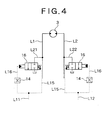
- unload valves 16, 16 may be individually provided in the both hydraulic lines L1, L2 ofthe hydraulic motor 3 instead of the communicating valve 10 as in the second modified embodiment shown in Fig. 4 to individually introduce each of the bypath lines L21, L22 into the tank.
Landscapes
- Engineering & Computer Science (AREA)
- Mining & Mineral Resources (AREA)
- Civil Engineering (AREA)
- General Engineering & Computer Science (AREA)
- Structural Engineering (AREA)
- Operation Control Of Excavators (AREA)
- Fluid-Pressure Circuits (AREA)
Abstract
Description
- The present invention relates to a rotating control circuit, in particular to a rotating control circuit for a construction machine.
- A hydraulic excavator, especially a hydraulic excavator with short tail swing radius has a small inertia force of upperrotating body at the time of stopping a rotating operation. For this reason, when the rotating operation is abruptly stopped, a machine body of the excavator may be flapped Furthermore, for the same reason, the machine body may also be flapped at the time of starting the rotation.
- It is an object of the present invention to provide a rotating control circuit which can avoid a flapping of a machine body at the time of stopping the rotation of upper rotating body of construction machine and the like.
- A construction machine according to the present invention has a rotating control circuit for a working machine provided with a rotating body, wherein the rotating control circuit comprises:
- a hydraulic motor adapted to be rotationally driven by supplying hydraulic fluid from hydraulic fluidsource by way of a direction control valve; operating means adapted to switch the direction control valve between a rotating position and a neutral position; a bypath lineconnected between both hydraulic lines ofthe hydraulic motor; a communicating valve having switch positions comprising a first position foclosing the bypath line and a second position for opening the bypath line; and a controlleradapted to control the switch positions of the communicating valve. The controller is adapted to set the communicating valve to the first position at the rotating position or the neutral position and to set the communicating valve to the second position when the communicating valve is switched toa position different from the first position, as well as to allow the hydraulic fluid of deceleration side at the time of stopping the rotation, and the hydraulic fluid of acceleration side at the time of starting the rotation, to be released by a predetermined time.
-
- The afore-mentioned "a position different from the first position" is illustrated by two cases as follows:
- First is the case where said controller is adapted to set an escape valve or a bypath valve to a closed position at the time when the operating means is operated for rotation, and to set the bypath valve to an open position at the time when the operating means is returned to the neutral position, thereby allowing the hydraulic fluid of deceleration side to be released by the predetermined time.
- In this case, a reverse motion of motor torque changed from acceleration to deceleration is delayed at the time of stopping the rotating operation. Thereby, an abrupt stopping will not be caused in the construction machine, in particular even if the inertia force of upper rotating body is small as in the hydraulic excavator with short tail swing radius, and there will be noflappingof a machine body of the excavator.
- Therefore, an operator does not feel lurch with his (her) body at the time of stopping the rotating operation and a comfortable maneuverability can be attained.
- Next is the case where said controller is adapted to set the communicating valve to the first position at the time when said operating means is in the neutral position and to set the communicating valve to the second position at the time when the rotating operation is started, thereby allowing the hydraulic fluid of acceleration side to be released by the predetermined time.
- In this case, an acceleration of motor torque is delayed at the time of starting the rotation. Therefore, even if the inertia force of upper rotating body is small as in the hydraulic excavator with short tail swing radius, the abrupt rotation will not be caused. As a result, there will be no rocking of hull. Thereby, the operator does not feel large rocking with his (her) body at the time of starting the rotation, whereby a comfortable maneuverability can be attained.
-
- Fig.1 is a diagram of rotating control circuit of hydraulic excavator according to the first embodiment of the present invention;
- Fig.2 is a diagram of rotating control circuit of hydraulic excavator according to the second embodiment of the present invention;
- Fig.3 is a diagram of partial rotating control circuit of hydraulic excavator according to the first modified embodiment of the present invention; and
- Fig.4 is a diagram of partial rotating control circuit of hydraulic excavator according to the second modified embodiment of the present invention.
-
- Hereinafter, each of the preferred embodiments of rotating control circuit according to the present invention will be described with reference to Figs. 1 to 4. This is one embodiment of the present invention and the present invention is not limit thereto.
- A hydraulic excavator, to which a rotating control circuit according to the present invention is applied, is generally provided with an upper rotating body on a lower traveling body. A hydraulic motor is employed in the rotating mechanism of the upper rotating body. The hydraulic motor is rotationally driven to perform a rotation by supplying hydraulic fluid from hydraulic fluidource such'as a hydraulic pump by way of a direction control valve. When the rotation is stopped, the direction control valve is switched to the neutral position.
- In the following embodiments, identical parts will be indicated by an identical reference numeral and only the different points thereof will be described without being repeatedly described.
- Fig. 1 is a diagram of rotating control circuit of hydraulic excavator according to the first embodiment of the present invention. In the figure, solid lines indicate hydraulic lines and broken lines indicate pilot lines.
- In Fig. 1, a
hydraulic pump 1 as a hydraulic fluidsource and ahydraulic motor 3 rotationally driven by pressure oil as hydraulic fluid from thepump 1 are connected with each other by both hydraulic lines L1, L2 through acontrol valve 5 as a direction control valve. - The
hydraulic pump 1 is of variable displacement type, which is driven by an engine (not shown). Thehydraulic motor 3 revolves an upper rotating body (not shown) of hydraulic excavator via adeceleration mechanism 4. - The
control valve 5 is of hydraulic pilot type, which is adapted to be switched to any of three switch positions a, b and c by a pilot pressure from aremote control valve 6 as an operating means. Among these, b is the neutral position. Theremote control valve 6 generates the pilot pressure as an operating signal of thecontrol valve 5 by transforming a hydraulic pressure from apilot pump 15 into a secondary pressure in response to the manipulation of operating lever. - In Fig. 1, the
remote control valve 6 is in the neutral position, and thus the pilot lines L11, L12 are not pressurized. Due to this, a spool of thecontrol valve 5 is in the neutral position b. In this neutral position b, the pressure oil from thehydraulic pump 1 is all returned to atank 7 and the both hydraulic lines L1, L2 ofthehydraulic motor 3 are blocked. Therefore, under this condition, thehydraulic motor 3 will revolve to neither left nor right directions. Thus, the upper rotating body will be maintained ina stopped condition or in a halt condition. - A rightward rotation is instructed by manipulating the lever of the
remote control valve 6. In this case, the pilot line L11 is pressurized and the spool of thecontrol valve 5 is switched to other position. In the switch position a, the pressure oil from thehydraulic pump 1 is supplied to thehydraulic motor 3 by way ofthe line L1. As a result, thehydraulic motor 3 is rotationally driven to the direction where the upper rotating body revolves rightward. And, the pressure oil discharged from thehydraulic motor 3 is returned to thetank 7 by way of the line L2. - A leftward rotation or a left-hand rotation is instructed by manipulating the lever of the
remote control valve 6. In this case, the pilot line L12 is pressurized and the spool of thecontrol valve 5 is switched to other position. In the switch position c, the pressure oil from thehydraulic pump 1 is supplied to thehydraulic motor 3 by way of the line L2. As a result, thehydraulic motor 3 is rotationally driven to the direction where the upper rotating body revolves leftward. And, the pressure oil discharged from thehydraulic motor 3 is returned to thetank 7 by way of the line L1. -
Overload relief valves - The
overload relief valves respective relief valves hydraulic motor 3 viacheck valves - The communicating
valve 10 is of hydraulic pilot type. Thisvalve 10 is so compact that it can be affixed to thehydraulic motor 3 or built in a reverse-preventing passageway of thehydraulic motor 3. Thevalve 10 is connected to the both hydraulic lines L1, L2 of thehydraulic motor 3 by bypath lines L3, L4. Thevalve 10 is switched to either switch positions d or e by pilot pressure from theremote valve 6 Between said two positions, the switch position d is the neutral position. - For the purpose of switching operation of the communicating
valve 10, lines L13, L14 are branched from the pilot lines L11, L12, respectively. Both of the lines L13, L14 are connected to the pilot lines L15, L16 of the communicatingvalve 10 via ashuttle valve 13. The pilot line L16 is provided with athrottle valve 14 as a controller. Thethrottle valve 14 controls the communicatingvalve 10 as explained below. Thevalve 14 can simply change the operating time (predetermined time) of the communicatingvalve 10 by selecting its size, in spite of its inexpensiveness and simple constitution. For this reason, it is possible to easily cope with needs of customers. - Hereinafter, the description will be made for the operation of communicating valve, which is one of the characteristic features of the present invention, as the subject.
- In Fig.1, the
remote control valve 6 is in the neutral position, and the pilot lines L11, L12 are not pressurized. For this reason, the spool of the communicatingvalve 10 is switched to the switch position d. In the switch position d, the bypath lines L3, L4 from the communicatingvalve 10 are blocked together. Furthermore, the pressure oil from thehydraulic pump 1 is all returned to thetank 7, and the both hydraulic lines L1, L2 ofhydraulic motor 3 are blocked. Therefore, under this condition, thehydraulic motor 3 will revolve toneither left nor right directions. For this reason, the upper rotating body is remained in the stopped condition as ever. - The rightward rotation is instructed by manipulating the lever ofthe
remote control valve 6. In this case, because the pilot line L11 is pressurized, the spool ofthecontrol valve 5 is switched to the switch position a. The pressure of pilot line L11 is transmitted to the pilot line L15 by way of the branch line L13 and theshuttle valve 13. After a little while, the pressure is also transmitted to the pilot line L16. In this case, the spool of the communicatingvalve 10 is in the state ofthe switch position d as it stands without being switched. - Then, the return-to-neutral is instructed by manipulating the lever of the
remote control valve 6. In this case, the pilot line L11 is not pressurized and the spool of thecontrol valve 5 is switched to the neutral position b. At this time, the pressure of the pilot line L15 of the communicatingvalve 10 is openedor released by way of theshuttle valve 13 and the branch lines L13, L14. Meanwhile, the pressure of the pilot line L16 is maintained in a condition higher than the pressure of the pilot line L15 by a predetermined time by the action of thethrottle valve 14. Within this predetermined time, the spool of the communicatingvalve 10 is switched to the switch position e. - In the switch position e, the bypath lines L3, L4 from the communicating
valve 10 are communicated with each other. Thereby, the both hydraulic lines L1, L2 of thehydraulic motor 3 are turned to the communicated state. Even in this case, the pressure oil from thehydraulic pump 1 is also all returned to thetank 7 and the both hydraulic lines L1, L2 of thehydraulic motor 3 are blockedby thecontrol valve 5. In this case, the pressure oil from the line L2 is returned to the line L1 by the communication of said bypath lines L3, L4, thereby preventing abrupt pressure rise in the line L2. - After the predetermined time, the pressure of the
pilot line 16 is turned to be as same as the pressure of thepilot line 15 and the spool of the communicatingvalve 10 is switched so that it springs back to be returned to the original switch position d. Thereby, the bypath lines L3, L4 from the communicatingvalve 10 are blocked together. In addition, the pressure oil from thehydraulic pump 1 is all returned to thetank 7, and the both hydraulic lines L1, L2 ofthehydraulic motor 3 are blocked. - And, the
overload relief valve 9 is operated and thebrake pressure is applied, whereby the upper rotating body is stopped. At this time, the abrupt pressure rise in the line L2 is prevented by the action of said communicatingvalve 10. Therefore, the upper rotating body slowly comes to be stopped. In this case, although thehydraulic motor 3 continuously performs the rightward rotation by the predetermined time, there is no substantial problem. The above case may be identically applied to the case where the leftward rotation is instructed by manipulating the lever oftheremote control valve 6. - According to this embodiment, the communicating
valve 10 is set to the switch position d (closed position) at the time when theremote control valve 6 is manipulated for rotating and set to the switch position e (open or release position) at the time when theremote control valve 6 is returned to the neutral, thereby functioning to allow the pressure oil of deceleration side to be escaped by a predetermined time. Accordingly, the inverse action of motor torque changed from acceleration to deceleration is delayed at the time of stopping the rotating operation. Therefore, no abrupt stop will be caused in a hydraulic excavator, in particular even if the inertia force of the upper rotating body is small as in a hydraulic excavator with short tail swing radius, and there will be no flapping of the machine body. Thereby, the operator does not feel lurch with his (her) body at the time of stopping the rotating operation, so that a comfortable maneuverability can be attained. - As described above, if the bypath lines are provided in the state of connecting the both hydraulic lines of hydraulic motor and constructed to allow the pressure oilas the hydraulic fluid to be escaped from the deceleration side to the acceleration side in the state where the bypath valve is set to the open position, it becomes needless to supplement the pressure oil. Therefore, it makes maintenance for the work machine easier.
- The hydraulic excavator, especially the hydraulic excavator with short tail swing radius also suffers from the flapping of the machine body at the time of starting the rotation due to the reasons as same as the reasons described in said first embodiment. According to the second embodiment, it is possible to prevent the flapping of the machine body at the time of starting the rotation.
- Fig. 2 shows a diagram of rotating control circuit of the hydraulic excavator according to the second embodiment of the present invention. In Fig. 2, the
throttle valve 14 as a controller is not present in the pilot line L16 of communicatingvalve 10 but is provided in the pilot line L15. The other construction is completely identical to the first embodiment and thus the description thereof will be omitted. - In Fig. 2, because the
remote control valve 6 is in the neutral position, the pilot lines L11, L12 are not pressurized. For this reason, the spool of the communicatingvalve 10 is in the switch position d. In this switch position d, the bypath lines L3, L4 from the communicatingvalve 10 are blocked together. In addition, the pressure oil from thehydraulic pump 1 is all returned to thetank 7, and the both hydraulic lines L1, L2 of thehydraulic motor 3 are blocked. Therefore, under this condition, thehydraulic motor 3 will revolve to neither left nor right directions. Thereby, the upper rotating body is maintained in the stopped stateor in a pause. - The rightward rotation is instructed by manipulating the lever ofthe
remote control valve 6. In this case, because the pilot line L11 is pressurized, the spool ofthecontrol valve 5 is switched to the switch position a. The pressure of pilot line L11 is transmitted to the pilot line L16 by way of the branch line L13 andshuttle valve 13. In this case, the pressure of the pilot line L15 is maintained in the stateof being lower than that of the pilot line L16 by a predetermined time by the action ofthrottle valve 14. Within this predetermined time, the spool ofthe communicatingvalve 10 is switched to the switch position e. - In the switch position e, the bypath lines L3, L4 from the communicating
valve 10 are turned to the state where they are communicated with each other. At this time, the pressure oil from thehydraulic pump 1 is supplied to the line L1 via thecontrol valve 5. The pressure oil of this line L1 is sent to the line L2 andthen returned to thetank 7, thereby preventing the abrupt pressure rise in the line L1. - After the predetermined time, the pressure of the pilot line L15 becomes equal to the pressure of the pilot line L16. For this reason, the spool of the communicating
valve 10 is switched so that it springs back to be returned to the former switch position d. Thereby, the bypath lines L3, L4 from the communicatingvalve 10 are blocked together. - As such, the pressure oil from the
hydraulic pump 1 is supplied to thehydraulic motor 3 by way of thecontrol valve 5 and line L1. As a result, thehydraulic motor 3 is rotationally driven in the direction for rotating the upper rotating body rightward. And, the pressure oil discharged from thehydraulic motor 3 is returned to thetank 7 by way of the line L2. The above may be identically applied to the case where the leftward rotation is instructed by manipulating the lever oftheremote control valve 6. - According to this embodiment, the communicating
valve 10 is set to the switch position d (closed position) at the time when theremote control valve 6 is in the neutral. In this case, the communicatingvalve 10 is set to the switch position e (openor release position) at the time of starting the rotation, thereby functioning to allow the pressure oil of acceleration side to be escaped or released by a predetermined time. Thereby, the acceleration of motor torque is delayed at the time of starting the rotation. Therefore, no abrupt rotation will be caused in the hydraulic excavator, in particular even if the inertia force of upper rotating body is small like the hydraulic excavator with short tail swing radius. As a result, there will be no flapping of the machine body. Due to this, the operator does not feel lurch with his (her) body at the time of starting the rotation, whereby a comfortable maneuverability can be attained. - Therefore, this embodiment provides a rotating control circuit comprising: a hydraulic motor rotationally driven as the pressure oil from a pressure oil source is supplied via a direction control valve; an operating means adapted to switch the direction control valve; a bypath line connected to both hydraulic lines of the hydraulic motor; a bypath valve having a position for closing the bypath line and a position for opening the bypath line; a controller for controlling the bypath valve, wherein said controller is adapted to set the bypath valve to the closed position at the time when the operating means is in the neutral and to set the bypath valve to the open position at the time when the rotating operation is started, thereby allowing the pressure oil of acceleration side to be escaped by a predetermined time.
- According to this construction, because the bypath valve is set to the closed position at the time when the operating means is in the neutral and set to the open position at the time when the rotating operation is started, thereby allowing the pressure oil of the acceleration side to be escaped by a predetermined time, the accelerating operation of motor torque is delayed at the time of starting the rotating operation. Therefore, no abrupt rotation will be caused in the hydraulic excavator, in particular even if the inertia force of upper rotating body is small like the hydraulic excavator with short tail swing radius and there will be no flapping of the machine body.
- Therefore, the operator does not feel lurch with his (her) body at the time of starting the rotation, whereby a comfortable maneuverability can be attained.
- Furthermore, said first and second embodiments provides the
throttle valve 14 as the controller in the pilot line L15 or L16 of the communicatingvalve 10 to set the communicatingvalve 10 to the open position by a predetermined time. - As described above, the communicating
valve 10 as an bypath valve is of hydraulic pilot type, and thethrottle valve 14 as a controller is installed in the pilot line of said bypath valve, whereby there isprovided with throttling to set the bypath valve to the open position by a predetermined time. Thereby, the reverse motion ofthe motor torque changed from acceleration to deceleration is delayed with a simple construction at the time of stopping the rotating operation. - The
throttle valve 14 may be substituted with a slow return check valve as in the first modified embodiment shown in Fig. 3. In addition, Fig. 3 shows an example adapted to delay the operating time of said communicatingvalve 10 using the stroke volume of thecontrol valve 5. - In said first and second embodiments, the communicating
valve 10 is of hydraulic pilot type and takes a more simple construction operated by the pilot pressure from theremote control valve 6. - Like this, if the bypath valve is adapted to be operated by the pilot pressure from the
remote control valve 6 as operating means, an exclusive source of pilot pressure will be unnecessary and the construction becomes more simplified. - If it is impossible to form a branch from the pilot lines L11, L12 of the
control valve 5, an exclusive source of pilot pressure may be provided. Furthermore, the communicatingvalve 10 may be of pneumatic pilot type or solenoid type. The opening area at the time of communicating the communicatingvalve 10 is not needed to be always constant. For example, if the opening area of communicating valve is adapted to be controllable, the communicating valve can produce abrake pressure. - In addition, unload
valves hydraulic motor 3 instead of the communicatingvalve 10 as in the second modified embodiment shown in Fig. 4 to individually introduce each of the bypath lines L21, L22 into the tank. In this case, it is preferable to provide a supplementary line which is not shown, so that shortage caused by allowing the pressure oil to be escaped to the tank is supplemented into the line L1 or L2. - Although an embodiment of the present invention isdisclosed in the above, the scope of protection of the present invention is not limited thereto.
Claims (9)
- A rotating control circuit for a working machine with a rotating body comprising:a hydraulic motor rotationally driven by supplying pressure oil from a hydraulic oil source via a direction control valve;an operating means adapted to switch said direction control valve between a rotating position and a neutral position;a bypath line connected between both hydraulic lines of said hydraulic motor;a communicating valve having switch positions with a first position and a second position, the first position being for closing said bypath line and the second position being for opening said bypath line; anda controller adapted to control the switch positions of said communicating valve, wherein the controller is adapted to set the communicating valve to the first position at said rotating position or said neutral position and then to set the communicating valve to the second position when theoperating means is operated to be switched to a position different from said first position, as well as to allow the pressure oil of deceleration side at the time of stopping rotation, or the pressure oil of acceleration side at the time of starting rotation to be released by a predetermined time.
- The rotating control circuit according to claim 1, wherein said controller is adapted to set said communicating valve to the first position at the rotating position of the time when said operating means is operated for rotating and to set said communicating valve to the second position at the time when the operating means is returned to the neutral position, as well as to allow the pressure oil of deceleration side to be released by a predetermined time.
- The rotating control circuit according to claim 1, wherein said controller is adapted to set said communicating valve to the first position when saidoperating means is in the neutral position and to set said communicating valve to the second position at the rotating position of the time when a rotating operation is started, as well as to allow the pressure oil of acceleration side to be released by a predetermined time.
- The rotating control circuit according to claim 1, wherein said communicating valve is of hydraulic pilot type.
- The rotating control circuit according to claim 4, wherein said controller is provided in a pilot line of said communicating valve and comprises a throttle valve, said throttle valve being adapted to set the communicating valve to the second position by a predetermined time.
- The rotating control circuit according to claim 5, wherein said communicating valve is operated bya pilot pressure from the operating means.
- The rotating control circuit according to claim 1, wherein said bypath line is provided in the state of connecting said both hydraulic lines ofsaid hydraulic motor, and adapted to allow the pressure oil to be released from the deceleration side to the acceleration side in the state where said communicating valve is set to the second position.
- A rotating control circuit for a working machine with a rotating body comprising:a hydraulic motor rotationally driven by supplying pressure oil from a pressure oil source via a direction control valve;an operating means adapted to switch said direction control valve;a bypath line connected to both hydraulic lines of said hydraulic motor;a communicating valvehaving a first position for closing said bypath line and a second position for opening said bypath line; anda controller adapted to control said communicating valve, wherein the controller is constructed to set the communicating valve to the first position at the time when said operating means is operated for rotating and to set the communicating valve to the second position at the time when the operating means is returned to a neutral position, thereby allowing the pressure oil of deceleration side to be released by a predetermined time.
- A rotating control circuit for a working machine with a rotating body comprising:a hydraulic motor rotationally driven by supplying pressure oil from a pressure oil source via a direction control valve;an operating means adapted to switch said direction control valve;a bypath line connected to both hydraulic lines of said hydraulic motor;a communicating valvehaving a first position for closing said bypath line and a second position for opening said bypath line; anda controller adapted to control said communicating valve, wherein the controller is adapted to set the communicating valve to the first position at the time when said operating means is in a neutral position and to set the communicating valve to the second position when a rotating operation is started, thereby allowing the pressure oil of acceleration side to be released by a predetermined time.
Applications Claiming Priority (2)
| Application Number | Priority Date | Filing Date | Title |
|---|---|---|---|
| JP2001301042A JP2003106305A (en) | 2001-09-28 | 2001-09-28 | Gyrating control circuit |
| JP2001301042 | 2001-09-28 |
Publications (2)
| Publication Number | Publication Date |
|---|---|
| EP1298256A2 true EP1298256A2 (en) | 2003-04-02 |
| EP1298256A3 EP1298256A3 (en) | 2005-06-15 |
Family
ID=19121520
Family Applications (1)
| Application Number | Title | Priority Date | Filing Date |
|---|---|---|---|
| EP02256386A Withdrawn EP1298256A3 (en) | 2001-09-28 | 2002-09-16 | Hydraulic system for suppression of vibrations of a working machine |
Country Status (5)
| Country | Link |
|---|---|
| US (1) | US6732513B2 (en) |
| EP (1) | EP1298256A3 (en) |
| JP (1) | JP2003106305A (en) |
| KR (1) | KR20030027762A (en) |
| CN (1) | CN1246596C (en) |
Cited By (3)
| Publication number | Priority date | Publication date | Assignee | Title |
|---|---|---|---|---|
| EP1722109A3 (en) * | 2005-05-09 | 2007-09-12 | Eaton Corporation | Anti jerk valve |
| CN104350216A (en) * | 2012-06-26 | 2015-02-11 | 神钢建机株式会社 | A work machine |
| EP2772590A4 (en) * | 2011-10-27 | 2015-11-25 | Volvo Constr Equip Ab | Hybrid excavator having a system for reducing actuator shock |
Families Citing this family (26)
| Publication number | Priority date | Publication date | Assignee | Title |
|---|---|---|---|---|
| KR100559296B1 (en) * | 2004-03-22 | 2006-03-15 | 볼보 컨스트럭션 이키프먼트 홀딩 스웨덴 에이비 | Vibration Control Method of Hydraulic Cylinder |
| US20060016186A1 (en) * | 2004-07-21 | 2006-01-26 | Xingen Dong | Hydrostatic transmission with bypass valve |
| DE102005053265B4 (en) * | 2005-11-08 | 2020-07-09 | Linde Hydraulics Gmbh & Co. Kg | Hydrostatic drive system |
| JP4855852B2 (en) * | 2006-07-04 | 2012-01-18 | 日立建機株式会社 | Motor controller for construction machinery |
| JP2009036300A (en) * | 2007-08-01 | 2009-02-19 | Kobelco Contstruction Machinery Ltd | Turn controlling device |
| JP5992196B2 (en) * | 2011-04-18 | 2016-09-14 | 株式会社ユーテック | Ram cylinder hydraulic circuit |
| JP5333511B2 (en) * | 2011-05-02 | 2013-11-06 | コベルコ建機株式会社 | Swivel work machine |
| WO2012150653A1 (en) * | 2011-05-02 | 2012-11-08 | コベルコ建機株式会社 | Rotation-type working machine |
| US8752373B2 (en) * | 2011-05-02 | 2014-06-17 | Kobelco Construction Machinery Co., Ltd. | Slewing type working machine |
| WO2012150651A1 (en) * | 2011-05-02 | 2012-11-08 | コベルコ建機株式会社 | Rotation-type working machine |
| US8944103B2 (en) | 2011-08-31 | 2015-02-03 | Caterpillar Inc. | Meterless hydraulic system having displacement control valve |
| US8966892B2 (en) | 2011-08-31 | 2015-03-03 | Caterpillar Inc. | Meterless hydraulic system having restricted primary makeup |
| IN2014DN03481A (en) * | 2011-10-06 | 2015-06-05 | Telsmith Inc | |
| JP5872363B2 (en) * | 2012-03-30 | 2016-03-01 | 住友建機株式会社 | Swing control device |
| KR101920088B1 (en) * | 2013-09-13 | 2018-11-19 | 현대건설기계 주식회사 | Swing Control System for Construction Equipment |
| CN104358286B (en) * | 2014-11-10 | 2016-06-29 | 广西柳工机械股份有限公司 | Deciliter stream selects function pilot operated valve device and loader to determine variable delivery hydraulic system |
| CN104728203B (en) * | 2015-03-26 | 2017-11-07 | 北京煤科天玛自动化科技有限公司 | A kind of electric-hydraulic control reversing valve with internal pressure relief function |
| US10344784B2 (en) * | 2015-05-11 | 2019-07-09 | Caterpillar Inc. | Hydraulic system having regeneration and hybrid start |
| CN106762880A (en) * | 2016-12-28 | 2017-05-31 | 中国航空工业集团公司西安飞机设计研究所 | A kind of airplane tail pillar hydraulic pressure folding and unfolding control system |
| CN107061389B (en) * | 2017-04-11 | 2018-12-14 | 长沙学院 | The Antisway Control System and method of engineering machinery rotary braking |
| CN107061390B (en) * | 2017-04-12 | 2018-12-14 | 长沙学院 | Antisway Control System and method during a kind of engineering machinery rotary braking |
| CN107152425B (en) * | 2017-06-29 | 2018-11-09 | 长沙学院 | Pressure-releasing type anti-swing control device and method in revolution positioning braking process |
| JP7119457B2 (en) | 2018-03-19 | 2022-08-17 | コベルコ建機株式会社 | construction machinery |
| KR102680206B1 (en) * | 2018-09-21 | 2024-07-02 | 엘에스엠트론 주식회사 | Transmission system of agricultural work vehicles |
| CN110409549A (en) * | 2019-06-28 | 2019-11-05 | 三一重机有限公司 | A kind of anti-rock hydraulic system, revolution executive device and excavator |
| US12085099B1 (en) * | 2020-06-18 | 2024-09-10 | Vacuworx Global, LLC | Flow control block for use with a vacuum material handler |
Family Cites Families (22)
| Publication number | Priority date | Publication date | Assignee | Title |
|---|---|---|---|---|
| JPS5645602A (en) | 1979-09-21 | 1981-04-25 | Nippon Berukuro Kk | Cutting apparatus of surface fastener ring |
| JPS5711305A (en) | 1980-06-23 | 1982-01-21 | Fujikura Ltd | Optical fiber cable |
| JPS57190104A (en) | 1981-05-18 | 1982-11-22 | Kawasaki Heavy Ind Ltd | Fluid actuator device |
| JPH076525B2 (en) | 1987-01-09 | 1995-01-30 | 株式会社神戸製鋼所 | Swing hydraulic circuit of construction machinery |
| JPH0517970A (en) * | 1991-07-08 | 1993-01-26 | Hitachi Constr Mach Co Ltd | Actuator control device for construction machine |
| JPH0542706A (en) | 1991-08-10 | 1993-02-23 | Sanyo Electric Co Ltd | Multigradation thermal recording method |
| US5419132A (en) * | 1992-07-14 | 1995-05-30 | Hitachi Construction Machinery Co., Ltd. | Inertial body drive mechanism |
| JPH06147201A (en) * | 1992-11-11 | 1994-05-27 | Kayaba Ind Co Ltd | Hydraulic motor drive circuit |
| JPH06337002A (en) * | 1993-05-27 | 1994-12-06 | Hitachi Constr Mach Co Ltd | Pressure control device of hydraulic machine |
| JPH0714202U (en) * | 1993-08-13 | 1995-03-10 | 株式会社小松製作所 | Vibration suppressor for work equipment |
| JPH08199631A (en) * | 1995-01-23 | 1996-08-06 | Hitachi Constr Mach Co Ltd | Hydraulic control equipment for construction machinery |
| JPH0960045A (en) * | 1995-08-22 | 1997-03-04 | Hitachi Constr Mach Co Ltd | Hydraulic motor control circuit |
| JPH0971977A (en) | 1995-09-05 | 1997-03-18 | Hitachi Constr Mach Co Ltd | Hydraulic motor control circuit |
| JP3256425B2 (en) | 1995-10-31 | 2002-02-12 | 新キャタピラー三菱株式会社 | Hydraulic control circuit for hydraulic motor |
| JPH09310701A (en) * | 1996-05-22 | 1997-12-02 | Hitachi Constr Mach Co Ltd | Inertial body inversion prevention device |
| JPH1054057A (en) * | 1996-08-09 | 1998-02-24 | Kubota Corp | Work vehicle hydraulic circuit structure |
| JPH10246205A (en) * | 1997-03-05 | 1998-09-14 | Shin Caterpillar Mitsubishi Ltd | Hydraulic control circuit device of hydraulic motor |
| JP4028090B2 (en) | 1998-06-18 | 2007-12-26 | コベルコ建機株式会社 | Hydraulic controller for work machine |
| JP2000170212A (en) | 1998-07-07 | 2000-06-20 | Yutani Heavy Ind Ltd | Hydraulic control equipment for work machines |
| JP2001027202A (en) | 1999-07-15 | 2001-01-30 | Hitachi Constr Mach Co Ltd | Brake circuit device for swing hydraulic motor |
| JP2001065506A (en) * | 1999-08-24 | 2001-03-16 | Kobe Steel Ltd | Construction equipment |
| US6474064B1 (en) * | 2000-09-14 | 2002-11-05 | Case Corporation | Hydraulic system and method for regulating pressure equalization to suppress oscillation in heavy equipment |
-
2001
- 2001-09-28 JP JP2001301042A patent/JP2003106305A/en active Pending
-
2002
- 2002-09-16 EP EP02256386A patent/EP1298256A3/en not_active Withdrawn
- 2002-09-27 US US10/255,957 patent/US6732513B2/en not_active Expired - Fee Related
- 2002-09-27 KR KR1020020058594A patent/KR20030027762A/en not_active Ceased
- 2002-09-28 CN CNB021437734A patent/CN1246596C/en not_active Expired - Fee Related
Non-Patent Citations (1)
| Title |
|---|
| None * |
Cited By (6)
| Publication number | Priority date | Publication date | Assignee | Title |
|---|---|---|---|---|
| EP1722109A3 (en) * | 2005-05-09 | 2007-09-12 | Eaton Corporation | Anti jerk valve |
| EP2772590A4 (en) * | 2011-10-27 | 2015-11-25 | Volvo Constr Equip Ab | Hybrid excavator having a system for reducing actuator shock |
| CN104350216A (en) * | 2012-06-26 | 2015-02-11 | 神钢建机株式会社 | A work machine |
| EP2865813A4 (en) * | 2012-06-26 | 2015-08-26 | Kobelco Constr Mach Co Ltd | Slewing work machine |
| US9366010B2 (en) | 2012-06-26 | 2016-06-14 | Kobelco Construction Machinery Co., Ltd. | Slewing-type working machine |
| CN104350216B (en) * | 2012-06-26 | 2016-09-14 | 神钢建机株式会社 | Swinging engineering machinery |
Also Published As
| Publication number | Publication date |
|---|---|
| KR20030027762A (en) | 2003-04-07 |
| CN1246596C (en) | 2006-03-22 |
| US6732513B2 (en) | 2004-05-11 |
| EP1298256A3 (en) | 2005-06-15 |
| CN1410683A (en) | 2003-04-16 |
| JP2003106305A (en) | 2003-04-09 |
| US20030061743A1 (en) | 2003-04-03 |
Similar Documents
| Publication | Publication Date | Title |
|---|---|---|
| US6732513B2 (en) | Rotating control circuit | |
| US7513109B2 (en) | Hydraulic controller for working machine | |
| US5919243A (en) | Work brake apparatus for wheel type excavator | |
| US7233853B2 (en) | Multiple mode operational system for work vehicle braking | |
| US4644849A (en) | Locking apparatus of inertial mass drive hydraulic circuit system | |
| JPH07332308A (en) | Hydraulic drive controller | |
| US5046312A (en) | Swivel speed control circuit for working vehicle | |
| US5493950A (en) | Variable priority device for swing motor in heavy construction equipment | |
| US20060089773A1 (en) | Multiple mode operational system for work vehicle propulsion | |
| JPH08105078A (en) | Variable priority device | |
| EP0415133B1 (en) | Hydraulic circuits for actuators | |
| JPH032722Y2 (en) | ||
| JP7152968B2 (en) | hydraulic excavator drive system | |
| JP2547441B2 (en) | Swing control circuit | |
| JP3739518B2 (en) | Brake device of hydraulic travel device | |
| JPH09302729A (en) | Brake circuit for swing motor of construction machine | |
| KR960004183Y1 (en) | Excavator drive transmission and actuator for parking brake | |
| JP2880365B2 (en) | Hydraulic motor drive circuit | |
| JPH045343A (en) | Hydraulic circuit for work device | |
| KR19980063238A (en) | Multi-purpose hydraulic controller of heavy equipment | |
| JP2006258237A (en) | Hydraulic motor unit | |
| JP2001065506A (en) | Construction equipment | |
| JP2001165104A (en) | Shockless valve and fluid pressure circuit | |
| JP3750764B2 (en) | Swivel control device for construction machinery | |
| KR920004542Y1 (en) | Speed reduction devices of excavator engine |
Legal Events
| Date | Code | Title | Description |
|---|---|---|---|
| PUAI | Public reference made under article 153(3) epc to a published international application that has entered the european phase |
Free format text: ORIGINAL CODE: 0009012 |
|
| AK | Designated contracting states |
Kind code of ref document: A2 Designated state(s): AT BE BG CH CY CZ DE DK EE ES FI FR GB GR IE IT LI LU MC NL PT SE SK TR Designated state(s): AT BE BG CH CY CZ DE DK EE ES FI FR GB GR IE IT LI LU MC NL PT SE SK TR |
|
| AX | Request for extension of the european patent |
Extension state: AL LT LV MK RO SI |
|
| PUAL | Search report despatched |
Free format text: ORIGINAL CODE: 0009013 |
|
| AK | Designated contracting states |
Kind code of ref document: A3 Designated state(s): AT BE BG CH CY CZ DE DK EE ES FI FR GB GR IE IT LI LU MC NL PT SE SK TR |
|
| AX | Request for extension of the european patent |
Extension state: AL LT LV MK RO SI |
|
| 17P | Request for examination filed |
Effective date: 20051207 |
|
| AKX | Designation fees paid |
Designated state(s): AT BE BG CH CY CZ DE DK EE ES FI FR GB GR IE IT LI LU MC NL PT SE SK TR |
|
| 17Q | First examination report despatched |
Effective date: 20060317 |
|
| STAA | Information on the status of an ep patent application or granted ep patent |
Free format text: STATUS: THE APPLICATION IS DEEMED TO BE WITHDRAWN |
|
| 18D | Application deemed to be withdrawn |
Effective date: 20070807 |