EP1298050A1 - Indicator of a motor-assisted bicycle - Google Patents
Indicator of a motor-assisted bicycle Download PDFInfo
- Publication number
- EP1298050A1 EP1298050A1 EP02014980A EP02014980A EP1298050A1 EP 1298050 A1 EP1298050 A1 EP 1298050A1 EP 02014980 A EP02014980 A EP 02014980A EP 02014980 A EP02014980 A EP 02014980A EP 1298050 A1 EP1298050 A1 EP 1298050A1
- Authority
- EP
- European Patent Office
- Prior art keywords
- assist
- motor
- power
- indicator
- display unit
- Prior art date
- Legal status (The legal status is an assumption and is not a legal conclusion. Google has not performed a legal analysis and makes no representation as to the accuracy of the status listed.)
- Granted
Links
Images





Classifications
-
- B—PERFORMING OPERATIONS; TRANSPORTING
- B62—LAND VEHICLES FOR TRAVELLING OTHERWISE THAN ON RAILS
- B62M—RIDER PROPULSION OF WHEELED VEHICLES OR SLEDGES; POWERED PROPULSION OF SLEDGES OR SINGLE-TRACK CYCLES; TRANSMISSIONS SPECIALLY ADAPTED FOR SUCH VEHICLES
- B62M6/00—Rider propulsion of wheeled vehicles with additional source of power, e.g. combustion engine or electric motor
- B62M6/40—Rider propelled cycles with auxiliary electric motor
- B62M6/55—Rider propelled cycles with auxiliary electric motor power-driven at crank shafts parts
-
- B—PERFORMING OPERATIONS; TRANSPORTING
- B62—LAND VEHICLES FOR TRAVELLING OTHERWISE THAN ON RAILS
- B62J—CYCLE SADDLES OR SEATS; AUXILIARY DEVICES OR ACCESSORIES SPECIALLY ADAPTED TO CYCLES AND NOT OTHERWISE PROVIDED FOR, e.g. ARTICLE CARRIERS OR CYCLE PROTECTORS
- B62J43/00—Arrangements of batteries
- B62J43/10—Arrangements of batteries for propulsion
- B62J43/13—Arrangements of batteries for propulsion on rider-propelled cycles with additional electric propulsion
-
- B—PERFORMING OPERATIONS; TRANSPORTING
- B62—LAND VEHICLES FOR TRAVELLING OTHERWISE THAN ON RAILS
- B62J—CYCLE SADDLES OR SEATS; AUXILIARY DEVICES OR ACCESSORIES SPECIALLY ADAPTED TO CYCLES AND NOT OTHERWISE PROVIDED FOR, e.g. ARTICLE CARRIERS OR CYCLE PROTECTORS
- B62J50/00—Arrangements specially adapted for use on cycles not provided for in main groups B62J1/00 - B62J45/00
- B62J50/20—Information-providing devices
- B62J50/21—Information-providing devices intended to provide information to rider or passenger
-
- B—PERFORMING OPERATIONS; TRANSPORTING
- B62—LAND VEHICLES FOR TRAVELLING OTHERWISE THAN ON RAILS
- B62M—RIDER PROPULSION OF WHEELED VEHICLES OR SLEDGES; POWERED PROPULSION OF SLEDGES OR SINGLE-TRACK CYCLES; TRANSMISSIONS SPECIALLY ADAPTED FOR SUCH VEHICLES
- B62M6/00—Rider propulsion of wheeled vehicles with additional source of power, e.g. combustion engine or electric motor
- B62M6/40—Rider propelled cycles with auxiliary electric motor
- B62M6/45—Control or actuating devices therefor
-
- B—PERFORMING OPERATIONS; TRANSPORTING
- B62—LAND VEHICLES FOR TRAVELLING OTHERWISE THAN ON RAILS
- B62M—RIDER PROPULSION OF WHEELED VEHICLES OR SLEDGES; POWERED PROPULSION OF SLEDGES OR SINGLE-TRACK CYCLES; TRANSMISSIONS SPECIALLY ADAPTED FOR SUCH VEHICLES
- B62M6/00—Rider propulsion of wheeled vehicles with additional source of power, e.g. combustion engine or electric motor
- B62M6/80—Accessories, e.g. power sources; Arrangements thereof
- B62M6/90—Batteries
-
- G—PHYSICS
- G01—MEASURING; TESTING
- G01R—MEASURING ELECTRIC VARIABLES; MEASURING MAGNETIC VARIABLES
- G01R31/00—Arrangements for testing electric properties; Arrangements for locating electric faults; Arrangements for electrical testing characterised by what is being tested not provided for elsewhere
- G01R31/36—Arrangements for testing, measuring or monitoring the electrical condition of accumulators or electric batteries, e.g. capacity or state of charge [SoC]
- G01R31/371—Arrangements for testing, measuring or monitoring the electrical condition of accumulators or electric batteries, e.g. capacity or state of charge [SoC] with remote indication, e.g. on external chargers
Definitions
- the present invention relates to an indicator of a motor-assisted bicycle, and particularly to an indicator of a motor-assisted bicycle that can display conditions of assist, regenerative charging and the like by an assist motor.
- a motor-assisted bicycle which includes a human power driving system for transmitting pedaling power applied to a pedal to a rear wheel and a motor driving system capable of adding assist power to the human power driving system according to the pedaling power.
- a human power driving system for transmitting pedaling power applied to a pedal to a rear wheel
- a motor driving system capable of adding assist power to the human power driving system according to the pedaling power.
- Japanese Patent Laid-Open No. 2000-72080 discloses an assist power controlling method of a motor-assisted bicycle for reducing battery wear by stopping supply of current to a motor or lowering the value of the current in conditions where assist power is not required, such as during traveling on a flat road.
- the motor-assisted bicycle is also known to perform regenerative charging during application of the brakes on a downward slope and the like to use energy efficiently.
- the conventional motor-assisted bicycle performs regenerative charging under predetermined conditions, and therefore no special consideration is given to regenerative charging adjusted to an intention or needs of the user and an indicator for indicating conditions of the regenerative charging.
- the present invention has been made in view of the prior art described above, and it is accordingly an object of the present invention to provide an indicator that displays conditions of assist, regenerative charging and the like and allows an operator to visually check the conditions in a motor-assisted bicycle capable of regenerative charging adjusted to an intention or needs of the user.
- the present invention has a first feature in that an indicator for displaying conditions of an assist motor of a battery-mounted motor-assisted bicycle that adds assist power to a human power driving system according to pedaling power applied to a pedal includes a first display unit for displaying an amount of regenerative charging of the battery.
- the operator can be aware of the amount of exercise of the operator and thus give strong recognition as a fitness tool to the bicycle.
- the operator is aware that the amount of exercise of the operator contributes to regenerative charging of the battery, and thus the operator can be motivated to exercise.
- the present invention has a second feature in that the indicator further includes a second display unit for displaying a control mode condition of the assist motor. According to this feature, the user can grasp control conditions of the assist motor, and thus can travel while recognizing excellent functions of the motor-assisted bicycle.
- the present invention has a third feature in that the indicator further includes: a push button; and a third display unit for displaying a battery charge level when the push button is operated. According to this feature, it is possible to grasp not only a condition of the regenerative charging and the control mode of the assist motor but also the charge level of the battery with the same indicator, and to thus use the indicator for multiple purposes. It is also possible for the user to check the charge level of the battery while in a riding position.
- FIG. 2 is a side view of a motor-assisted bicycle according to the embodiment of the present invention.
- a vehicle frame 2 of the motor-assisted bicycle includes: a head pipe 21 situated at the front of the frame; a down pipe 22 extending down rearward from the head pipe 21; and a seat post 23 rising upward from about an end portion of the down pipe 22.
- a portion where the down pipe 22 and the seat post 23 are joined to each other and the periphery of that portion are covered by a resin cover 33, which is divided into two parts, that is, an upper and a lower part for attachment and detachment.
- a steering handlebar 27 is rotatably inserted via a handlebar post 27A into an upper portion of the head pipe 21.
- a front fork 26, connected to the handlebar post 27A, is supported at a lower portion of the head pipe 21.
- a front wheel WF is rotatably journaled at a lower end of the front fork 26.
- an indicator 28 for displaying conditions of an assist motor that is, an indicator 28 for displaying an assist condition, a regenerative charge condition and the like of the bicycle is attached to a central portion of the steering handlebar 27.
- a position for attaching the indicator 28 is not limited to the central portion of the steering handlebar 27; the position for attaching the indicator 28 may be one of a right and a left position 28A and 28B of the steering handlebar 27, or another position.
- an electric assist unit 1 serving as a driving unit including an electric motor (not shown) for pedaling power assist is bolted and hung at three positions, that is, a connecting portion 92 at a lower end of the down pipe 22, a connecting portion 91 provided at a front portion of a battery bracket 49 welded to the seat post 23, and a connecting portion 90 at a rear portion of the bracket 49.
- a chain stay 25 is bolted in conjunction with the electric assist unit 1 at the connecting portion 90.
- a power supply switch unit (or mode switch) 29 of the electric assist unit 1 is disposed adjacent to the head pipe 21 on the down pipe 22.
- the power supply switch unit 29 allows selection of an eco mode (details will be described later) for reducing power consumption and a super eco mode (details will be described later) for reducing power consumption and increasing the frequency of regenerative charge. While the power supply switch unit 29 can be turned on by a key, the power supply switch unit 29 may be turned on by using an infrared signal and a remote control switch, for example. In that case, the power supply switch unit 29 is provided with a receiver for receiving the infrared signal sent from the remote control switch.
- the electric assist unit 1 has a driving sprocket 13. Rotation of a crankshaft 101 is transmitted from the driving sprocket 13 through a chain 6 to a rear sprocket 14.
- the handlebar 27 is provided with a brake lever 27B. An operation of the brake lever 27B is transmitted through a brake wire 39 to a brake unit (not shown) of a rear wheel WR.
- a brake switch (not shown) that is turned on when the brake lever 27B is operated is provided, and the operation of the brake lever 27B is detected by the brake switch.
- crankshaft 101 is rotatably supported in the electric assist unit 1, and pedals 12 are journaled at both a right and a left end of the crankshaft 101 via a crank 11.
- the rear wheel WR serving as a driving wheel is journaled between ends of the pair of right and left chain stays 25 extending from the electric assist unit 1 to the rear side.
- a pair of right and left seat stays 24 is provided between an upper portion of the seat post 23 and the ends of both the chain stays 25.
- a seat pipe 31 provided with a seat 30 at an upper end thereof for adjusting height of the seat 30 is inserted in the seat post 23 so as to be slidable in the seat post 23.
- a battery 4 is mounted in the rear of the seat post 23 and under the seat 30.
- the battery 4 is housed in a housing case and then attached to the battery bracket 49.
- the battery 4 includes a plurality of battery cells, and is mounted along the seat post 23 so that a longitudinal direction of the battery 4 is a substantially vertical direction.
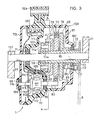
- FIG. 3 is a sectional view of the electric assist unit 1
- FIG. 4 is a view taken along an arrow line A-A in FIG. 3.
- a case of the electric assist unit 1 is formed by a main body 70, and a left cover 70L and a right cover 70R that are attached to both sides of the main body 70.
- the case 70, the left cover 70L, and the right cover 70R are produced from a molded resin product for lighter weight.
- Hangers 90a, 91a, and 92a conforming to the connecting portions 90, 91, and 92, respectively, of the down pipe 22 and the battery bracket 49 are formed around the periphery of the case main body 70.
- a bearing 71 is provided in the main body 70, and a bearing 72 is provided in the right cover 70R.
- the crankshaft 101 is in contact with the inside of an inner ring of the bearing 71, and a sleeve 73 provided to the crankshaft 101 on the same axis as that of the crankshaft 101 so as to be slidable in a direction of an outer circumference of the crankshaft 101 is in contact with the inside of an inner ring of the bearing 72.
- the crankshaft 101 is supported by the bearing 71 and the bearing 72.
- a boss 74 is fixed to the sleeve 73, and an assist gear 76 is provided on the periphery of the boss 74 with a one-way clutch 75 formed by a ratchet mechanism, for example, intermediate between the boss 74 and the assist gear 76.
- the assist gear 76 be made of resin from a viewpoint of weight reduction, and be a helical gear from a viewpoint of quietness and the like.
- a gear 73a is formed at an end portion of the sleeve 73.
- Three planet gears 77 are arranged on the periphery of the gear 73a with the gear 73a serving as a sun gear.
- the planet gears 77 are supported by shafts 77a disposed in standing relation to a supporting plate 102, and the supporting plate 102 is supported by the crankshaft 101 with a one-way clutch 78 intermediate between the supporting plate 102 and the crankshaft 101.
- the planet gears 77 are engaged with an inner gear formed on the inner periphery of a pedaling power detecting ring 79.
- the driving sprocket 13 connected to the rear sprocket 14 via the chain 6 is fixed to an end portion (side having no gear formed) of the sleeve 73.
- the pedaling power detecting ring 79 has arms 79a and 79b projecting from the periphery of the pedaling power detecting ring 79.
- the arms 79a and 79b are biased in a direction (clockwise direction in the figure) opposite to a rotating direction of the crankshaft 101 at the time of travel by an extension spring 80 provided between the arm 79a and the main body 70 and a compression spring 81 provided between the arm 79b and the main body 70.
- the compression spring 81 is provided to prevent wobbling of the ring 79.
- the arm 79b is provided with a potentiometer 82 for detecting displacement in a rotating direction of the ring 79.
- a clutch plate 86 for regeneration is disposed adjacent to the assist gear 76 with a spring washer 85 intermediate between the clutch plate 86 and the assist gear 76.
- a pressure plate 87 for pressing the clutch plate 86 to the assist gear 76 side against action of the spring washer is disposed adjacent to the clutch plate 86. Both the clutch plate 86 and the pressure plate 87 are provided so as to be slidable in a direction of the axis of the sleeve 73.
- the pressure plate 87 is biased to the clutch plate 86 side by a cam 88 in contact with an inclined surface formed on a hub portion of the pressure plate 87.
- the cam 88 is rotatably supported from the right cover 70R by a shaft 89.
- An actuator 7 is fixed to an end portion of the shaft 89, that is, a portion projecting from the right cover 70R to the exterior thereof.
- the actuator 7 is controlled by a regeneration control signal supplied from a controller 100.
- the actuator 7 rotates by a controlled amount, the cam 88 correspondingly rotates on the shaft 89.
- a solenoid may be used instead of the actuator 7.
- the assist gear 76 is engaged with a pinion 83 fixed to a shaft of the assist motor M.
- the assist motor M is a three-phase brushless motor.
- the assist motor M includes: a rotor 111 having a magnetic pole 110 of a neodymium (Nd-Fe-B) magnet; a stator coil 112 provided around the periphery of the rotor; a rubber magnet ring (ring formed by alternately arranging north poles and south poles) 113 for a magnetic pole sensor, provided on a side of the rotor 111; a Hall IC 115 disposed opposite to the rubber magnet ring 113 and mounted on a substrate 114; and a shaft 116 of the rotor 111.
- the shaft 116 is supported by a bearing 98 provided in the left cover 70L and a bearing 99 provided in the case main body 70.
- the controller 100 including a FET and a capacitor for a driver for controlling the assist motor M and the actuator 7 is provided on the front frame side of the case main body 70. Power is supplied through the FET to the stator coil 112 and the actuator 7. The controller 100 operates the assist motor M and the actuator 7 according to the pedaling power detected by the potentiometer 82 serving as a pedaling power detector to thereby cause assist power and regeneration.
- reinforcing members 105, 106, and 107 of metal such as iron, aluminum, aluminum alloy, or copper alloy are disposed around the periphery of the bearings.
- reinforcing members to be disposed in the case main body 70 in particular, reinforce parts where heavy loads are expected, such as the bearing 71 for the crankshaft 101, the bearing 99 for the motor shaft 116, and the hangers 90a, 91a, and 92a serving as members for attachment to the vehicle frame, the reinforcing members of the parts are joined to each other to form an integral reinforcing plate 105. With this reinforcing plate 105, the reinforcing members disposed around the bearings and the hangers can further enhance the reinforcing effect in conjunction with each other.
- the reinforcing plate 105 is not limited to the one formed by joining all the reinforcing members around the bearing 71, the bearing 99, and the hangers 90a, 91a, and 92a; the reinforcing plate 105 may be formed by joining adjacent ones of the reinforcing members, such for example as the reinforcing member around the hanger 90a and the reinforcing member around the bearing 99, or the reinforcing member around the bearing 71 and the reinforcing member around the bearing 99 or one of the hangers 90a, 91a, and 92a.
- the pedaling power detecting ring 79 When a load is applied to the rear wheel WR, the pedaling power detecting ring 79 is rotated according to the magnitude of the load, and the amount of rotation is detected by the potentiometer 82.
- the assist motor M When an output of the potentiometer 82, that is, an output corresponding to the load is higher than a predetermined value, the assist motor M is energized according to the magnitude of the load to generate assist power.
- the assist power is combined with driving torque generated in the crankshaft 101 by human power, and then transmitted to the driving sprocket 13.
- the brake switch When the brakes are applied to decelerate the vehicle during traveling, the brake switch is turned on, and then the actuator 7 is driven to rotate by a predetermined amount. Then, the cam 88 is rotated on the shaft 89, whereby the pressure plate 87 presses the clutch plate 86. Subsequently, the clutch plate 86 is biased to the assist gear 76 side, thereby the boss 74 and the assist gear 76 are coupled to each other, and rotation of the boss 74 is transmitted to the assist gear 76. Thus, rotation of the driving sprocket 13 during braking is transmitted through the sleeve 73, the boss 74, and the assist gear 76 to the pinion 83. The pinion 83 is rotated to thereby generate an electromotive force in the stator coil 112, and thus regeneration is performed. A current resulting from the generation is supplied to the battery 4 via the controller 100 to charge the battery 4.
- the present embodiment allows selection by operation of the operator of a mode in which assist is cut when predetermined control criteria are satisfied, as at the time of traveling a flat road, assist is resumed when predetermined other control criteria are satisfied, and regenerative charging is performed while the brake switch is on (hereinafter referred to as an "eco mode"), and a mode in which regenerative charging is performed when predetermined control criteria are satisfied during traveling on a flat road and during traveling on a downward slope, and assist is resumed when predetermined other control criteria are satisfied (hereinafter referred to as a "super eco mode").
- FIG. 5 is a plan view of an example of the power supply switch unit 29.
- the modes can be selected by inserting a key not shown in the figure into a keyhole 32 and rotating the key.
- the key When the key is in an "OFF" position, power to the electric assist unit 1 is off, and therefore no power is supplied from the battery 4 to the electric assist unit 1.
- the assist motor M When the key is rotated to an "ON" position, power can be supplied to the electric assist unit 1, and where pedaling power exceeds a predetermined value, the assist motor M is controlled to provide assist power according to a ratio (assist ratio) between the assist power and the pedaling power which ratio is read from a preset map.
- the key When the key is set to an "ECO" position, the eco mode is selected and it is possible to effect control to start and cut assist according to predetermined control criteria, as will be described in detail later.
- the super eco mode is selected and it is possible to effect control to start assist and perform regenerative charging according to predetermined control criteria, as will be described in detail later.
- Control for assist, assist cut, and regenerative charge in the eco mode and control for assist and regenerative charge in the super eco mode will next be described.
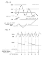
- FIG. 6 is a diagram of assistance in explaining conditions for assist cut, showing a pedaling power history and also showing a counter value CNTBT of a counter updated on the basis of the magnitude of the pedaling power.
- the pedaling power is varied periodically in such a manner as to correspond to a rotation cycle of the crank.
- a pedaling power upper limit value TRQUP and a pedaling power lower limit value TRQBT are set.
- the pedaling power upper limit value TRQUP is set in a range of 15 to 20 kgf, for example, and the pedaling power lower limit value TRQBT is set in a range of 13 to 15 kgf, for example.
- the pedaling power is detected by interrupt processing at intervals of 10 milliseconds, for example.
- the counter value CNTBT of the low level counter is incremented (+1), and when the pedaling power TRQA is the pedaling power upper limit value TRQUP or higher, the counter value CNTBT of the low level counter is decremented (-1).
- the counter value CNTBT is not changed.
- the counter value CNTBT exceeds a reference value (counter reference value) TTED, it is determined that the pedaling power TRQA is at the assist cut level, and thereby assist is cut.
- the counter value CNTBT can be reset when the pedaling power TRQA exceeds a reset level RESET set at a point higher than the pedaling power upper limit value TRQUP, or when conditions for starting assist, which will be described later, are satisfied. Also, regenerative charging is performed on preset conditions while the brake switch is on.
- the regenerative charging in the super eco mode is performed on the same conditions as those of assist cut in the eco mode. Specifically, when the counter value CNTBT exceeds the reference value (counter reference value) TTED, it is determined that the pedaling power TRQA is at a regenerative charging level, and thereby regenerative charging is performed.
- a counter value KSR for conditions for starting regenerative charging is defined; however, the counter value KSR and the counter value CNTBT can be considered to be the same value.
- FIG. 7 is a diagram of assistance in explaining conditions for starting assist, showing a pedaling power history and also showing a counter value CNTASL updated each time the pedaling power exceeds a reference value.
- a reference value TRQASL of pedaling power level which is a factor in determining a start of assist, is set, and the number of times that a peak value of the varying pedaling power TRQA exceeds the reference value TRQASL is set as the counter value CNTASL of an assist start counter.
- the counter value CNTASL is decremented (-1) each time a peak value of the pedaling power TRQA exceeds the reference value TRQASL.
- FIG. 7 shows an example where an initial value of the counter value CNTASL is "3."
- the peak value of the pedaling power TRQA exceeds the reference value TRQASL and therefore the counter value CNTASL is decremented twice.
- the peak value in a next variation cycle does not exceed the reference value TRQASL, and therefore the counter value CNTASL is reset to the initial value at a time t3.
- the counter value CNTASL is decremented at times t4, t5, and t6 to "0.”
- the reference value TRQASL can be set at a plurality of levels, and counter values CNTASL each corresponding to one of the levels and different from those of the other levels can be set.
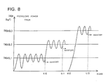
- FIG. 8 is a diagram of assistance in explaining conditions for starting assist at each of the reference values when the plurality of reference values TRQASL are set, the diagram showing a pedaling power history.
- a reference value TRQASL1 corresponds to pedaling power at the time of gradual acceleration during cruising on a flat road, and is set at 20 kgf, for example.
- a reference value TRQASL2 corresponds to pedaling power at the time of entering a gentle upward slope, and is set at 30 kgf, for example.
- a reference value TRQASL3 corresponds to pedaling power at the time of starting to move, going up a steep slope, or sharp acceleration during cruising, and is set at 35 kgf, for example.
- a counter value CNTASL1 corresponding to the reference value TRQASL1 is set at "5.”
- a counter value CNTASL2 corresponding to the reference value TRQASL2 is set at "3.”
- a counter value CNTASL3 corresponding to the reference value TRQASL3 is set at "2.”
- the counter value CNTASL1 is "0" and the pedaling power TRQA exceeds the reference value TRQASL1, whereby assist is started with a pedaling power ratio (assist ratio) corresponding to the reference value TRQASL1.
- the counter value CNTASL2 is "0" and the pedaling power TRQA exceeds the reference value TRQASL2, whereby the assist is changed to assist with an assist ratio corresponding to the reference value TRQASL2.
- the counter value CNTASL3 is "0" and the pedaling power TRQA exceeds the reference value TRQASL3, whereby assist is started with an assist ratio corresponding to the reference value TRQASL3.
- the counter values CNTASL1 to CNTASL3 are initialized when assist is stopped and when a CPU is reset.
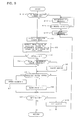
- FIG. 9 is a flowchart illustrating main parts of processing in the eco mode including the assist and the assist cut described with reference to FIG. 6 and FIG. 7.
- a step S12 whether the brake switch is turned on is determined, and when the determination is negative, the processing proceeds to a step S1, and when the determination is positive, the processing proceeds to a step S13.
- step S13 regenerative braking is continued while the brake switch is on (determination is positive at a step S14).
- the processing proceeds to a step S15 to stop the regenerative braking.
- the pedaling power TRQA is detected.
- the peak value of the pedaling power TRQA is detected.
- the counter value CNTASL is decremented, and when the peak value of the pedaling power TRQA does not exceed the reference value TRQASL, the counter value CNTASL is reset.
- whether the pedaling power is at the assist level corresponding to the reference value TRQASL is determined on the basis of whether the counter value CNTASL is "0.”
- whether the pedaling power TRQA (current value) exceeds the reference value TRQASL is determined.
- step S4 When the determination at the step S4 is positive, that is, when the pedaling power is at the predetermined level and the current pedaling power TRQA has exceeded the reference value TRQASL, the processing proceeds to a step S5 to allow assist.
- assist power is calculated on the basis of an assist ratio determined from the reference value TRQASL of the pedaling power and the vehicle speed, and then an output of the assist motor M is controlled so as to provide the assist power.
- step S6 whether the pedaling power is at the assist cut level is determined on the basis of relation in magnitude between the pedaling power TRQA and the pedaling power upper limit value TRQUP and the pedaling power lower limit value TRQBT.
- step S7 according to a result of the determination at the step S6, the counter value CNTBT is incremented when the level of the pedaling power is +1 (step S7).
- the counter value CNTBT is decremented when the level of the pedaling power is -1 (step S8).
- step S9 without changing the counter value CNTBT. Reversely, the counter value CNTBT may be decremented when the pedaling power is at the assist cut level, and the counter value CNTBT may be incremented otherwise.
- step S9 whether the pedaling power TRQA remains at a predetermined low level, that is, the assist cut level is determined on the basis of whether the counter value CNTBT has reached the reference value TTED.
- the initial value of the counter value CNTBT is set to be the reference value TTED, and whether the pedaling power TRQA remains at the assist cut level is determined on the basis of whether the counter value CNTBT has reached zero.
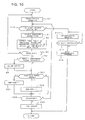
- FIG. 10 is a flowchart illustrating main parts of processing in the super eco mode including the assist and the regenerative charging described with reference to FIG. 6 and FIG. 7. Since control to allow assist is the same as in the eco mode (FIG. 9), the processing for the control to allow assist is identified by the same reference numerals, that is, the steps S1 to S5, and its description will be omitted.
- regenerative charging is performed.
- a step S12 whether the brake switch is turned on is determined.
- the brake switch is turned on when the brake lever 27B is operated.
- a braking amount detecting potentiometer may be provided in place of the brake switch to use a voltage value of the braking amount detecting potentiometer.
- the processing proceeds to a step S13, whereas when the determination at the step S12 is negative, the processing proceeds to the step S1.
- regenerative braking is performed.
- whether the brake switch is turned off is determined.
- step S15 the processing proceeds to a step S15 to stop the regenerative braking.
- the steps S12 to S15 represent conventionally performed regenerative braking.
- the assist allowing processing is followed by regenerative charging start level processing at a step S21.
- whether the pedaling power is at a regenerative charging start level is determined on the basis of relation in magnitude between the pedaling power TRQA and the pedaling power upper limit value TRQUP and the pedaling power lower limit value TRQBT.
- the counter value KSR is incremented when the level of the pedaling power is +1 (step S22).
- the counter value KSR is decremented when the level of the pedaling power is -1 (step S23).
- the processing proceeds to a step S24 without changing the counter value KSR. Reversely, the counter value KSR may be decremented when the pedaling power is at the regenerative charging start level, and the counter value KSR may be incremented otherwise.
- the initial value of the counter value KSR is set to be the reference value KSRCH, and whether the pedaling power remains at the regenerative charging start level is determined on the basis of whether the counter value KSR has reached zero.
- the processing returns and proceeds to the step S11 to perform regenerative charging.
- the determination at the step S24 is negative, the pedaling power is not at the regenerative charging start level, and thus the processing returns to the step S12 to repeat the processing steps described above.
- the pedaling power lower limit value TRQBT in FIG. 6 is set lower, for example set lower than the range of 13 to 15 kgf, it is possible to perform regenerative charging only at the time of descending a slope.
- FIG. 11 is a block diagram of functions of main parts of the controller 100 for processing in the super eco mode.
- the functions can be realized by a microcomputer including a CPU.
- output data (vehicle speed V) of a vehicle speed sensor 40 is captured by an assist power map 41 and a regenerative charging map 52 in predetermined interruption timing.
- Output data (pedaling power TRQA) of the potentiometer 82 serving as a pedaling power sensor is captured by the assist power map 41.
- An on/off output of the brake switch is captured by the regenerative charging map 52.
- Assist power data is set in the assist power map 41 to provide a predetermined assist ratio on the basis of the vehicle speed V and the pedaling power TRQA.
- Regeneration data is set in the regenerative charging map 52 to perform predetermined regenerative charging based on the vehicle speed when the brake switch is turned on.
- the assist power map 41 outputs assist power data.
- the assist power map is for example set so as to decrease the assist power, that is, lower the assist ratio even at the same pedaling power TRQA as the vehicle speed V is increased.
- the regenerative charging map 52 outputs regeneration data (regeneration control signal) corresponding to the vehicle speed when the brake switch 51 is turned on.
- the regenerative charging map is for example set such that the amount of regenerative charging is increased as the vehicle speed is increased.
- the assist power data and the regeneration data are inputted to a driving/regeneration driver 42.
- the driving/regeneration driver 42 controls an output of the assist motor M or the actuator 7 according to the assist power data or the regeneration data.
- the vehicle speed sensor 40 can be formed for example by means that magnetically detects regular projections and depressions provided on the periphery of the supporting plate 102 in the electric assist unit 1 and outputs the vehicle speed V on the basis of the number of projections and depressions detected or detection intervals of projections and depressions.
- a pedaling power determining unit 43 determines the magnitude of the current pedaling power TRQA with respect to pedaling power reference values (for example the pedaling power upper limit value TRQUP and the pedaling power lower limit value TRQBT), and increments or decrements the counter value KSR of a low level counter 44 according to a result of the determination.
- a comparator unit 45 compares the counter value KSR of the low level counter 44 with the reference value KSRCH, and outputs a regeneration instruction KCI to the driving/regeneration driver 42 when the counter value KSR has reached the reference value KSRCH.
- the pedaling power determining unit 43, the low level counter 44, and the comparator unit 45 form regeneration level detecting means.
- a peak value detecting unit 46 is supplied with the pedaling power TRQA from the pedaling power sensor 82, and detects a peak value of the periodically varying pedaling power TRQA.
- the peak value is inputted to a pedaling power level determining unit 47.
- the pedaling power level determining unit 47 updates the counter value CNTASL of an assist counter 48 when the pedaling power level determining unit 47 determines that the peak value exceeds the predetermined pedaling power level TRQASL.
- the assist counter 48 outputs an assist allowing instruction AI when the counter value CNTASL has reached a predetermined value.
- the assist allowing instruction is inputted to the driving/regeneration driver 42 via a gate G.
- a second pedaling power determining unit 50 outputs a detection signal when the current pedaling power TRQA exceeds the pedaling power level TRQASL.
- the gate G is opened when the detection signal of the second pedaling power determining unit 50 is supplied, whereby the assist allowing instruction is inputted to the driving/regeneration driver 42.
- the peak value detecting unit 46, the pedaling power level determining unit 47, and the assist counter 48 form varying pedaling power level detecting means.
- the driving/regeneration driver 42 energizes the assist motor M to provide assist or the actuator 7 to perform regenerative charging. Specifically, a conduction angle of a FET forming the driver circuit of the assist motor M or the actuator 7 is determined according to the assist power data or the regeneration data to thereby control the magnitude of the assist power or the amount of regeneration.
- the pedaling power level determining unit 47 outputs a reset signal to reset the counter value of the assist counter 48 to an initial value when the peak value does not exceed the pedaling power level TRQASL.
- FIG. 12 is a diagram providing a rough summary of control of the assist motor according to traveling conditions in each of the STD, ECO, and S-ECO modes. Although the figure does not represent the control of the assist motor accurately, the figure is provided because the figure may help roughly understand differences between the STD, ECO, and S-ECO modes. It is clear from the figure that the S-ECO mode can increase the frequency of regenerative charging as compared with the STD and ECO modes.
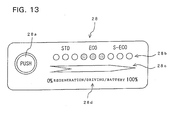
- FIG. 13 is a plan view of the indicator 28 according to one embodiment of the present invention.
- the indicator 28 displays a charge level of the battery, an assist condition, a regenerative charge condition and the like.
- the indicator 28 includes: a push button 28a; mode display lamps 28b that blink when the STD (standard mode), ECO (eco mode), and S-ECO (super eco mode) are selected, the mode display lamps 28b being formed by three lamps for each of the modes; a bar graph display unit 28c for displaying 0 to 100%; and a type display unit 28d for indicating that the type of quantity shown by the bar graph represents either one of "regeneration,” "driving,” and “battery.”
- three lamps of the mode display lamps may be substituted for the display of the bar graph display unit.
- the mode display lamps 28b can be formed by a light-emitting diode, for example, and the bar graph display unit 28c and the type display unit 28d can be formed by a liquid crystal.
- FIG. 14 is a flowchart of operation of the indicator 28 and a driving unit 64 (see FIG. 1) of the indicator 28.
- determination at steps S32 to S34 is made.
- the processing proceeds to a step S35, where three lamps of the mode display lamps 28b allocated for the STD blink for a few seconds.
- the processing proceeds to a step S36, where ECO lamps blink for a few seconds.
- step S34 the processing proceeds to a step S37, where S-ECO lamps blink for a few seconds.
- the user can confirm which mode is selected. Incidentally, since the lamps blink only for a few seconds, battery consumption can be reduced.
- step S38 determines whether the power supply switch unit 29 is turned off.
- step S39 determines whether the push button 28a is pressed.
- step S40 determines whether the power supply switch unit 29 is turned off.
- step S42 whether the push button 28a is pressed is determined. While the determinations at the steps S41 and S42 are both negative, the charge level of the battery is displayed on the bar graph display unit 28c.
- the processing proceeds to steps from S43 on down.
- the charge level of the battery is displayed for an odd-numbered time that the push button 28a is pressed, while the display of the charge level of the battery is turned off for an even-numbered time that the push button 28a is pressed.
- the determination at the step S42 is changed to determination of "whether a predetermined time has passed," the display of the charge level of the battery will be automatically turned off in the predetermined time.
- step S43 whether regenerative charging is being performed is determined.
- the processing proceeds to a step S44 to display the "regeneration” and display the amount of regenerative charging on the bar graph display unit 28c.
- step S45 determines whether assist is being provided.
- step S46 determines whether an operation for mode change is performed.
- the processing proceeds to the steps S32 to S34 to determine the selected mode.
- the processing proceeds to the step S38 to repeat operations at the steps S38 to S46.
- the indicator 28 is turned off.
- a glance at display on the indicator 28 shows the user which of the STD, ECO, and S-ECO modes is selected, the extent of the assist, or the amount of regenerative charging during traveling, thus allowing the user to do the cycling with pleasure.
- Regeneration display in particular allows the user to be aware of the amount of exercise of the user himself/herself and thus give renewed recognition as a fitness tool to the motor-assisted bicycle.
- FIG. 1 is a block diagram showing a circuit configuration around the indicator 28.
- a mode selected at the power supply switch unit 29 is detected by a mode detecting unit 61, and a mode signal is supplied to an indicator driving unit 64.
- the charge level of the battery 4 is detected by a battery charge level detecting unit 62, and then supplied to the indicator driving unit 64.
- a current sensor 63 detects current supplied to and from the battery, and outputs a result to the indicator driving unit 64.
- the indicator driving unit 64 performs operations described with reference to the flowchart of FIG. 14. When the changing of the mode is detected by the mode detecting unit 61, the indicator driving unit 64 blinks the mode display lamps 28b of the indicator 28 for a few seconds.
- the indicator driving unit 64 displays the “battery” and displays the charge level of the battery on the bar graph display unit 28c.
- the indicator driving unit 64 displays the amount of regeneration and driving on the basis of the current obtained by the current sensor 63 on the bar graph display unit 28c.
- the user can be made aware that the amount of exercise of the user contributes to regenerative charging during traveling, thus giving renewed recognition as a fitness tool to the motor-assisted bicycle.
- the user is aware that the amount of exercise of the user is stored in the battery and is not wasted, and thus the user feels invigorated.
- the user can grasp conditions of the assist motor at a glance, and thus can travel while recognizing excellent functions of the motor-assisted bicycle according to the present invention.
- the user can grasp the charge level of the battery anytime by operating the push button, and thus can prevent battery exhaustion.
- conditions of the assist motor can be visually displayed to the operator during traveling, and thus it is possible to increase the attraction of the motor-assisted bicycle as a product.
- an indicator 28 attached to a part of a handlebar of a motor-assisted bicycle includes: a push button 28a; mode display lamps 28b for displaying conditions of an assist motor, that is, a standard (STD) mode, an ECO mode, and an S-ECO mode; a bar graph 28c; and a type display unit 28d for displaying either one of "regeneration,” "driving,” and "battery.”
- mode display lamps 28b for displaying conditions of an assist motor, that is, a standard (STD) mode, an ECO mode, and an S-ECO mode
- a bar graph 28c for displaying either one of "regeneration,” "driving,” and "battery.
- the regeneration (driving) on the type display unit 28d is displayed brightly and an amount of regenerative charging (assist) is displayed on the bar graph 28c.
- the push button 28a is pressed, the battery on the type display unit 28d is displayed brightly and a battery charge level is displayed on the bar graph 28c.
Landscapes
- Engineering & Computer Science (AREA)
- Chemical & Material Sciences (AREA)
- Combustion & Propulsion (AREA)
- Mechanical Engineering (AREA)
- Transportation (AREA)
- Electric Propulsion And Braking For Vehicles (AREA)
Abstract
Description
- The present invention relates to an indicator of a motor-assisted bicycle, and particularly to an indicator of a motor-assisted bicycle that can display conditions of assist, regenerative charging and the like by an assist motor.
- A motor-assisted bicycle is known which includes a human power driving system for transmitting pedaling power applied to a pedal to a rear wheel and a motor driving system capable of adding assist power to the human power driving system according to the pedaling power. With the motor-assisted bicycle, it is desirable to alleviate battery wear and thereby extend a distance traveled on a single charge. Japanese Patent Laid-Open No. 2000-72080, for example, discloses an assist power controlling method of a motor-assisted bicycle for reducing battery wear by stopping supply of current to a motor or lowering the value of the current in conditions where assist power is not required, such as during traveling on a flat road.
- The motor-assisted bicycle is also known to perform regenerative charging during application of the brakes on a downward slope and the like to use energy efficiently.
- However, the conventional motor-assisted bicycle performs regenerative charging under predetermined conditions, and therefore no special consideration is given to regenerative charging adjusted to an intention or needs of the user and an indicator for indicating conditions of the regenerative charging.
- The present invention has been made in view of the prior art described above, and it is accordingly an object of the present invention to provide an indicator that displays conditions of assist, regenerative charging and the like and allows an operator to visually check the conditions in a motor-assisted bicycle capable of regenerative charging adjusted to an intention or needs of the user.
- In order to achieve the above object, the present invention has a first feature in that an indicator for displaying conditions of an assist motor of a battery-mounted motor-assisted bicycle that adds assist power to a human power driving system according to pedaling power applied to a pedal includes a first display unit for displaying an amount of regenerative charging of the battery. According to this feature, the operator can be aware of the amount of exercise of the operator and thus give strong recognition as a fitness tool to the bicycle. In addition, the operator is aware that the amount of exercise of the operator contributes to regenerative charging of the battery, and thus the operator can be motivated to exercise.
- Moreover, the present invention has a second feature in that the indicator further includes a second display unit for displaying a control mode condition of the assist motor. According to this feature, the user can grasp control conditions of the assist motor, and thus can travel while recognizing excellent functions of the motor-assisted bicycle.
- Furthermore, the present invention has a third feature in that the indicator further includes: a push button; and a third display unit for displaying a battery charge level when the push button is operated. According to this feature, it is possible to grasp not only a condition of the regenerative charging and the control mode of the assist motor but also the charge level of the battery with the same indicator, and to thus use the indicator for multiple purposes. It is also possible for the user to check the charge level of the battery while in a riding position.
- A preferred embodiment of the present invention will hereinafter be described with reference to the drawings, in which:
- FIG. 1 is a block diagram showing a circuit around an indicator according to the present invention.
- FIG. 2 is a side view of a motor-assisted bicycle.
- FIG. 3 is a sectional view of main parts of an electric assist unit.
- FIG. 4 is a sectional view taken along an arrow line A-A in FIG. 3.
- FIG. 5 is a plan view of an example of a power supply switch unit.
- FIG. 6 is a diagram of assistance in explaining conditions for assist cut, showing a pedaling power history.
- FIG. 7 is a diagram of assistance in explaining conditions for starting assist, showing a pedaling power history.
- FIG. 8 is a diagram of assistance in explaining conditions for starting assist at a plurality of pedaling power levels, the diagram showing a pedaling power history.
- FIG. 9 is a flowchart illustrating main parts of processing in an eco mode including the assist and the assist cut.
- FIG. 10 is a flowchart illustrating main parts of processing in a super eco mode including the assist and regenerative charging.
- FIG. 11 is a block diagram of functions of main parts of a regeneration control apparatus according to an embodiment of the present invention.
- FIG. 12 is a diagram of assistance in explaining a rough summary of control of an assist motor according to traveling conditions in each of an STD, an ECO, and an S-ECO mode.
- FIG. 13 is a plan view of an embodiment of the indicator according to the present invention.
- FIG. 14 is a flowchart mainly illustrating operation of an indicator driving unit.
-
- FIG. 2 is a side view of a motor-assisted bicycle according to the embodiment of the present invention.
- A
vehicle frame 2 of the motor-assisted bicycle includes: ahead pipe 21 situated at the front of the frame; adown pipe 22 extending down rearward from thehead pipe 21; and aseat post 23 rising upward from about an end portion of thedown pipe 22. A portion where thedown pipe 22 and theseat post 23 are joined to each other and the periphery of that portion are covered by aresin cover 33, which is divided into two parts, that is, an upper and a lower part for attachment and detachment. Asteering handlebar 27 is rotatably inserted via ahandlebar post 27A into an upper portion of thehead pipe 21. Afront fork 26, connected to thehandlebar post 27A, is supported at a lower portion of thehead pipe 21. A front wheel WF is rotatably journaled at a lower end of thefront fork 26. - As shown in an enlarged front view enclosed by a broken line, an
indicator 28 for displaying conditions of an assist motor (details will be described later), that is, anindicator 28 for displaying an assist condition, a regenerative charge condition and the like of the bicycle is attached to a central portion of thesteering handlebar 27. A position for attaching theindicator 28 is not limited to the central portion of thesteering handlebar 27; the position for attaching theindicator 28 may be one of a right and aleft position 28A and 28B of thesteering handlebar 27, or another position. - In a lower portion of the
vehicle frame 2, anelectric assist unit 1 serving as a driving unit including an electric motor (not shown) for pedaling power assist is bolted and hung at three positions, that is, a connectingportion 92 at a lower end of thedown pipe 22, a connecting portion 91 provided at a front portion of abattery bracket 49 welded to theseat post 23, and a connectingportion 90 at a rear portion of thebracket 49. Achain stay 25 is bolted in conjunction with theelectric assist unit 1 at the connectingportion 90. - A power supply switch unit (or mode switch) 29 of the
electric assist unit 1 is disposed adjacent to thehead pipe 21 on thedown pipe 22. The powersupply switch unit 29 allows selection of an eco mode (details will be described later) for reducing power consumption and a super eco mode (details will be described later) for reducing power consumption and increasing the frequency of regenerative charge. While the powersupply switch unit 29 can be turned on by a key, the powersupply switch unit 29 may be turned on by using an infrared signal and a remote control switch, for example. In that case, the powersupply switch unit 29 is provided with a receiver for receiving the infrared signal sent from the remote control switch. - The
electric assist unit 1 has a drivingsprocket 13. Rotation of acrankshaft 101 is transmitted from the drivingsprocket 13 through achain 6 to arear sprocket 14. Thehandlebar 27 is provided with abrake lever 27B. An operation of thebrake lever 27B is transmitted through abrake wire 39 to a brake unit (not shown) of a rear wheel WR. In addition, a brake switch (not shown) that is turned on when thebrake lever 27B is operated is provided, and the operation of thebrake lever 27B is detected by the brake switch. - The
crankshaft 101 is rotatably supported in theelectric assist unit 1, andpedals 12 are journaled at both a right and a left end of thecrankshaft 101 via acrank 11. The rear wheel WR serving as a driving wheel is journaled between ends of the pair of right and left chain stays 25 extending from theelectric assist unit 1 to the rear side. A pair of right and left seat stays 24 is provided between an upper portion of theseat post 23 and the ends of both the chain stays 25. Aseat pipe 31 provided with aseat 30 at an upper end thereof for adjusting height of theseat 30 is inserted in theseat post 23 so as to be slidable in theseat post 23. - A
battery 4 is mounted in the rear of theseat post 23 and under theseat 30. Thebattery 4 is housed in a housing case and then attached to thebattery bracket 49. Thebattery 4 includes a plurality of battery cells, and is mounted along theseat post 23 so that a longitudinal direction of thebattery 4 is a substantially vertical direction. - FIG. 3 is a sectional view of the
electric assist unit 1, and FIG. 4 is a view taken along an arrow line A-A in FIG. 3. A case of theelectric assist unit 1 is formed by amain body 70, and aleft cover 70L and aright cover 70R that are attached to both sides of themain body 70. Thecase 70, theleft cover 70L, and theright cover 70R are produced from a molded resin product for lighter weight.Hangers portions down pipe 22 and thebattery bracket 49 are formed around the periphery of the casemain body 70. Abearing 71 is provided in themain body 70, and a bearing 72 is provided in theright cover 70R. Thecrankshaft 101 is in contact with the inside of an inner ring of thebearing 71, and asleeve 73 provided to thecrankshaft 101 on the same axis as that of thecrankshaft 101 so as to be slidable in a direction of an outer circumference of thecrankshaft 101 is in contact with the inside of an inner ring of the bearing 72. Thus, thecrankshaft 101 is supported by thebearing 71 and the bearing 72. - A
boss 74 is fixed to thesleeve 73, and anassist gear 76 is provided on the periphery of theboss 74 with a one-way clutch 75 formed by a ratchet mechanism, for example, intermediate between theboss 74 and theassist gear 76. It is desirable that theassist gear 76 be made of resin from a viewpoint of weight reduction, and be a helical gear from a viewpoint of quietness and the like. - A
gear 73a is formed at an end portion of thesleeve 73. Three planet gears 77 are arranged on the periphery of thegear 73a with thegear 73a serving as a sun gear. The planet gears 77 are supported byshafts 77a disposed in standing relation to a supportingplate 102, and the supportingplate 102 is supported by thecrankshaft 101 with a one-way clutch 78 intermediate between the supportingplate 102 and thecrankshaft 101. The planet gears 77 are engaged with an inner gear formed on the inner periphery of a pedalingpower detecting ring 79. The drivingsprocket 13 connected to therear sprocket 14 via thechain 6 is fixed to an end portion (side having no gear formed) of thesleeve 73. - The pedaling
power detecting ring 79 hasarms power detecting ring 79. Thearms crankshaft 101 at the time of travel by anextension spring 80 provided between thearm 79a and themain body 70 and acompression spring 81 provided between thearm 79b and themain body 70. Thecompression spring 81 is provided to prevent wobbling of thering 79. Thearm 79b is provided with apotentiometer 82 for detecting displacement in a rotating direction of thering 79. - A
clutch plate 86 for regeneration is disposed adjacent to theassist gear 76 with aspring washer 85 intermediate between theclutch plate 86 and theassist gear 76. Apressure plate 87 for pressing theclutch plate 86 to theassist gear 76 side against action of the spring washer is disposed adjacent to theclutch plate 86. Both theclutch plate 86 and thepressure plate 87 are provided so as to be slidable in a direction of the axis of thesleeve 73. - The
pressure plate 87 is biased to theclutch plate 86 side by acam 88 in contact with an inclined surface formed on a hub portion of thepressure plate 87. Thecam 88 is rotatably supported from theright cover 70R by ashaft 89. Anactuator 7 is fixed to an end portion of theshaft 89, that is, a portion projecting from theright cover 70R to the exterior thereof. As is clear from later description, theactuator 7 is controlled by a regeneration control signal supplied from acontroller 100. When theactuator 7 rotates by a controlled amount, thecam 88 correspondingly rotates on theshaft 89. Incidentally, a solenoid may be used instead of theactuator 7. - The
assist gear 76 is engaged with apinion 83 fixed to a shaft of the assist motor M. The assist motor M is a three-phase brushless motor. The assist motor M includes: arotor 111 having amagnetic pole 110 of a neodymium (Nd-Fe-B) magnet; astator coil 112 provided around the periphery of the rotor; a rubber magnet ring (ring formed by alternately arranging north poles and south poles) 113 for a magnetic pole sensor, provided on a side of therotor 111; aHall IC 115 disposed opposite to therubber magnet ring 113 and mounted on asubstrate 114; and ashaft 116 of therotor 111. Theshaft 116 is supported by abearing 98 provided in theleft cover 70L and abearing 99 provided in the casemain body 70. - The
controller 100 including a FET and a capacitor for a driver for controlling the assist motor M and theactuator 7 is provided on the front frame side of the casemain body 70. Power is supplied through the FET to thestator coil 112 and theactuator 7. Thecontroller 100 operates the assist motor M and theactuator 7 according to the pedaling power detected by thepotentiometer 82 serving as a pedaling power detector to thereby cause assist power and regeneration. - While it is desirable to form the case
main body 70, thecovers electric assist unit 1 according to the present embodiment, reinforcingmembers main body 70, in particular, reinforce parts where heavy loads are expected, such as the bearing 71 for thecrankshaft 101, the bearing 99 for themotor shaft 116, and thehangers plate 105. With this reinforcingplate 105, the reinforcing members disposed around the bearings and the hangers can further enhance the reinforcing effect in conjunction with each other. - The reinforcing
plate 105 is not limited to the one formed by joining all the reinforcing members around thebearing 71, thebearing 99, and thehangers plate 105 may be formed by joining adjacent ones of the reinforcing members, such for example as the reinforcing member around thehanger 90a and the reinforcing member around thebearing 99, or the reinforcing member around thebearing 71 and the reinforcing member around the bearing 99 or one of thehangers members case 70 and thecovers - In the thus formed
electric assist unit 1, when pedaling power is applied to thecrankshaft 101 via thecrank 11, thecrankshaft 101 is rotated. The rotation of thecrankshaft 101 is transmitted to the supportingplate 102 via the one-way clutch 78, thereby theshafts 77a of the planet gears 77 are revolved around thesun gear 73a, and thesun gear 73a is rotated via the planet gears 77. The rotation of thesun gear 73a rotates the drivingsprocket 13 fixed to thesleeve 73. - When a load is applied to the rear wheel WR, the pedaling
power detecting ring 79 is rotated according to the magnitude of the load, and the amount of rotation is detected by thepotentiometer 82. When an output of thepotentiometer 82, that is, an output corresponding to the load is higher than a predetermined value, the assist motor M is energized according to the magnitude of the load to generate assist power. The assist power is combined with driving torque generated in thecrankshaft 101 by human power, and then transmitted to the drivingsprocket 13. - When the brakes are applied to decelerate the vehicle during traveling, the brake switch is turned on, and then the
actuator 7 is driven to rotate by a predetermined amount. Then, thecam 88 is rotated on theshaft 89, whereby thepressure plate 87 presses theclutch plate 86. Subsequently, theclutch plate 86 is biased to theassist gear 76 side, thereby theboss 74 and theassist gear 76 are coupled to each other, and rotation of theboss 74 is transmitted to theassist gear 76. Thus, rotation of the drivingsprocket 13 during braking is transmitted through thesleeve 73, theboss 74, and theassist gear 76 to thepinion 83. Thepinion 83 is rotated to thereby generate an electromotive force in thestator coil 112, and thus regeneration is performed. A current resulting from the generation is supplied to thebattery 4 via thecontroller 100 to charge thebattery 4. - The present embodiment allows selection by operation of the operator of a mode in which assist is cut when predetermined control criteria are satisfied, as at the time of traveling a flat road, assist is resumed when predetermined other control criteria are satisfied, and regenerative charging is performed while the brake switch is on (hereinafter referred to as an "eco mode"), and a mode in which regenerative charging is performed when predetermined control criteria are satisfied during traveling on a flat road and during traveling on a downward slope, and assist is resumed when predetermined other control criteria are satisfied (hereinafter referred to as a "super eco mode"). FIG. 5 is a plan view of an example of the power
supply switch unit 29. - In the figure, the modes can be selected by inserting a key not shown in the figure into a
keyhole 32 and rotating the key. When the key is in an "OFF" position, power to theelectric assist unit 1 is off, and therefore no power is supplied from thebattery 4 to theelectric assist unit 1. When the key is rotated to an "ON" position, power can be supplied to theelectric assist unit 1, and where pedaling power exceeds a predetermined value, the assist motor M is controlled to provide assist power according to a ratio (assist ratio) between the assist power and the pedaling power which ratio is read from a preset map. When the key is set to an "ECO" position, the eco mode is selected and it is possible to effect control to start and cut assist according to predetermined control criteria, as will be described in detail later. When the key is set to an "S-ECO" position, the super eco mode is selected and it is possible to effect control to start assist and perform regenerative charging according to predetermined control criteria, as will be described in detail later. Incidentally, it is desirable to attach the powersupply switch unit 29 to the vehicle frame such that the "ON" position is directed in a traveling direction of the vehicle. - Control for assist, assist cut, and regenerative charge in the eco mode and control for assist and regenerative charge in the super eco mode will next be described.
- In the eco mode, assist is cut when a pedaling power history is detected and it is determined that the pedaling power remains at a level lower than a predetermined value and thus requiring no assist (hereinafter referred to as an "assist cut level"). FIG. 6 is a diagram of assistance in explaining conditions for assist cut, showing a pedaling power history and also showing a counter value CNTBT of a counter updated on the basis of the magnitude of the pedaling power. Incidentally, the pedaling power is varied periodically in such a manner as to correspond to a rotation cycle of the crank. In the figure, a pedaling power upper limit value TRQUP and a pedaling power lower limit value TRQBT are set. The pedaling power upper limit value TRQUP is set in a range of 15 to 20 kgf, for example, and the pedaling power lower limit value TRQBT is set in a range of 13 to 15 kgf, for example. The pedaling power is detected by interrupt processing at intervals of 10 milliseconds, for example.
- When the pedaling power TRQA is the pedaling power lower limit value TRQBT or lower, the counter value CNTBT of the low level counter is incremented (+1), and when the pedaling power TRQA is the pedaling power upper limit value TRQUP or higher, the counter value CNTBT of the low level counter is decremented (-1). When the pedaling power TRQA is higher than the pedaling power lower limit value TRQBT and lower than the pedaling power upper limit value TRQUP, the counter value CNTBT is not changed. When the counter value CNTBT exceeds a reference value (counter reference value) TTED, it is determined that the pedaling power TRQA is at the assist cut level, and thereby assist is cut.
- The counter value CNTBT can be reset when the pedaling power TRQA exceeds a reset level RESET set at a point higher than the pedaling power upper limit value TRQUP, or when conditions for starting assist, which will be described later, are satisfied. Also, regenerative charging is performed on preset conditions while the brake switch is on.
- The regenerative charging in the super eco mode is performed on the same conditions as those of assist cut in the eco mode. Specifically, when the counter value CNTBT exceeds the reference value (counter reference value) TTED, it is determined that the pedaling power TRQA is at a regenerative charging level, and thereby regenerative charging is performed. In order to facilitate understanding of description in the following, a counter value KSR for conditions for starting regenerative charging is defined; however, the counter value KSR and the counter value CNTBT can be considered to be the same value.
- Control for starting assist in the eco mode and the super eco mode will next be described. When a pedaling power history is detected and it is determined that the pedaling power is at a level requiring assist power (hereinafter referred to as an "assist level"), assist based on an assist ratio corresponding to the predetermined level is provided. FIG. 7 is a diagram of assistance in explaining conditions for starting assist, showing a pedaling power history and also showing a counter value CNTASL updated each time the pedaling power exceeds a reference value. In the figure, a reference value TRQASL of pedaling power level, which is a factor in determining a start of assist, is set, and the number of times that a peak value of the varying pedaling power TRQA exceeds the reference value TRQASL is set as the counter value CNTASL of an assist start counter. In this case, the counter value CNTASL is decremented (-1) each time a peak value of the pedaling power TRQA exceeds the reference value TRQASL. When the counter value CNTASL becomes "0" and the pedaling power TRQA exceeds the reference value TRQASL, it is determined that the pedaling power is at an assist requiring level, and thus conditions for starting assist are satisfied.
- Specifically, FIG. 7 shows an example where an initial value of the counter value CNTASL is "3." In the figure, at times t1 and t2, the peak value of the pedaling power TRQA exceeds the reference value TRQASL and therefore the counter value CNTASL is decremented twice. The peak value in a next variation cycle does not exceed the reference value TRQASL, and therefore the counter value CNTASL is reset to the initial value at a time t3. Thereafter, the counter value CNTASL is decremented at times t4, t5, and t6 to "0." When the pedaling power TRQA exceeds the reference value TRQASL at a time t7, the conditions for starting assist are satisfied, whereby assist is started.
- The reference value TRQASL can be set at a plurality of levels, and counter values CNTASL each corresponding to one of the levels and different from those of the other levels can be set. FIG. 8 is a diagram of assistance in explaining conditions for starting assist at each of the reference values when the plurality of reference values TRQASL are set, the diagram showing a pedaling power history. In the figure, a reference value TRQASL1 corresponds to pedaling power at the time of gradual acceleration during cruising on a flat road, and is set at 20 kgf, for example. A reference value TRQASL2 corresponds to pedaling power at the time of entering a gentle upward slope, and is set at 30 kgf, for example. A reference value TRQASL3 corresponds to pedaling power at the time of starting to move, going up a steep slope, or sharp acceleration during cruising, and is set at 35 kgf, for example. A counter value CNTASL1 corresponding to the reference value TRQASL1 is set at "5." A counter value CNTASL2 corresponding to the reference value TRQASL2 is set at "3." A counter value CNTASL3 corresponding to the reference value TRQASL3 is set at "2." These settings may of course be made arbitrarily according to characteristics of the vehicle and the user.
- With such settings, referring to FIG. 8, at a time t10 after gradual acceleration during cruising on a flat road, the counter value CNTASL1 is "0" and the pedaling power TRQA exceeds the reference value TRQASL1, whereby assist is started with a pedaling power ratio (assist ratio) corresponding to the reference value TRQASL1. At a time t11 after entering a gentle upward slope, the counter value CNTASL2 is "0" and the pedaling power TRQA exceeds the reference value TRQASL2, whereby the assist is changed to assist with an assist ratio corresponding to the reference value TRQASL2. At a time t13 a short time after a traveling start time t12, the counter value CNTASL3 is "0" and the pedaling power TRQA exceeds the reference value TRQASL3, whereby assist is started with an assist ratio corresponding to the reference value TRQASL3.
- The counter values CNTASL1 to CNTASL3 are initialized when assist is stopped and when a CPU is reset.
- FIG. 9 is a flowchart illustrating main parts of processing in the eco mode including the assist and the assist cut described with reference to FIG. 6 and FIG. 7. First, at a step S12, whether the brake switch is turned on is determined, and when the determination is negative, the processing proceeds to a step S1, and when the determination is positive, the processing proceeds to a step S13. At the step S13, regenerative braking is continued while the brake switch is on (determination is positive at a step S14). When the brake switch is turned off, the processing proceeds to a step S15 to stop the regenerative braking.
- Next, at the step S1, the pedaling power TRQA is detected. At a step S2, the peak value of the pedaling power TRQA is detected. When the peak value of the pedaling power TRQA exceeds the reference value TRQASL, the counter value CNTASL is decremented, and when the peak value of the pedaling power TRQA does not exceed the reference value TRQASL, the counter value CNTASL is reset. At a step S3, whether the pedaling power is at the assist level corresponding to the reference value TRQASL is determined on the basis of whether the counter value CNTASL is "0." At a step S4, whether the pedaling power TRQA (current value) exceeds the reference value TRQASL is determined.
- When the determination at the step S4 is positive, that is, when the pedaling power is at the predetermined level and the current pedaling power TRQA has exceeded the reference value TRQASL, the processing proceeds to a step S5 to allow assist. In this assist, assist power is calculated on the basis of an assist ratio determined from the reference value TRQASL of the pedaling power and the vehicle speed, and then an output of the assist motor M is controlled so as to provide the assist power.
- At a step S6, whether the pedaling power is at the assist cut level is determined on the basis of relation in magnitude between the pedaling power TRQA and the pedaling power upper limit value TRQUP and the pedaling power lower limit value TRQBT. At a step S7, according to a result of the determination at the step S6, the counter value CNTBT is incremented when the level of the pedaling power is +1 (step S7). The counter value CNTBT is decremented when the level of the pedaling power is -1 (step S8). When the level of the pedaling power is 0, the processing proceeds to a step S9 without changing the counter value CNTBT. Reversely, the counter value CNTBT may be decremented when the pedaling power is at the assist cut level, and the counter value CNTBT may be incremented otherwise.
- At the step S9, whether the pedaling power TRQA remains at a predetermined low level, that is, the assist cut level is determined on the basis of whether the counter value CNTBT has reached the reference value TTED. In the case where the counter value CNTBT is decremented when the pedaling power TRQA is at the assist cut level, the initial value of the counter value CNTBT is set to be the reference value TTED, and whether the pedaling power TRQA remains at the assist cut level is determined on the basis of whether the counter value CNTBT has reached zero. When it is determined that the pedaling power remains at the assist cut level, the processing proceeds to a step S10 to cut the assist.
- FIG. 10 is a flowchart illustrating main parts of processing in the super eco mode including the assist and the regenerative charging described with reference to FIG. 6 and FIG. 7. Since control to allow assist is the same as in the eco mode (FIG. 9), the processing for the control to allow assist is identified by the same reference numerals, that is, the steps S1 to S5, and its description will be omitted.
- At a step S11, regenerative charging is performed. At a step S12, whether the brake switch is turned on is determined. The brake switch is turned on when the
brake lever 27B is operated. Incidentally, a braking amount detecting potentiometer may be provided in place of the brake switch to use a voltage value of the braking amount detecting potentiometer. When the determination at the step S12 is positive, the processing proceeds to a step S13, whereas when the determination at the step S12 is negative, the processing proceeds to the step S1. At the step S13, regenerative braking is performed. At the step S14, whether the brake switch is turned off is determined. When the brake switch is not turned off, the regenerative braking is continued, whereas when the brake switch is turned off, the processing proceeds to a step S15 to stop the regenerative braking. During the regenerative braking, the higher the vehicle speed, the larger the amount of regenerative charging. When the regenerative braking is stopped, the processing returns to the step S11. Incidentally, the steps S12 to S15 represent conventionally performed regenerative braking. - When the determination at the step S12 is negative, the processing for allowing assist is performed at the steps S1 to S5.
- The assist allowing processing is followed by regenerative charging start level processing at a step S21. Specifically, as shown in FIG. 6, whether the pedaling power is at a regenerative charging start level is determined on the basis of relation in magnitude between the pedaling power TRQA and the pedaling power upper limit value TRQUP and the pedaling power lower limit value TRQBT. At a step S22, according to a result of the determination at the step S21, the counter value KSR is incremented when the level of the pedaling power is +1 (step S22). The counter value KSR is decremented when the level of the pedaling power is -1 (step S23). When the level of the pedaling power is 0, the processing proceeds to a step S24 without changing the counter value KSR. Reversely, the counter value KSR may be decremented when the pedaling power is at the regenerative charging start level, and the counter value KSR may be incremented otherwise.
- At the step S24, whether the pedaling power TRQA remains at a predetermined low level, that is, the regenerative charging start level is determined on the basis of whether the counter value KSR has reached a reference value KSRCH (= TTED). In the case where the counter value KSR is decremented when the pedaling power is at the regenerative charging start level, the initial value of the counter value KSR is set to be the reference value KSRCH, and whether the pedaling power remains at the regenerative charging start level is determined on the basis of whether the counter value KSR has reached zero. When it is determined that the pedaling power remains at the regenerative charging start level (the determination at the step S24 is positive), assist is cut at a step S25. Then the processing returns and proceeds to the step S11 to perform regenerative charging. When the determination at the step S24 is negative, the pedaling power is not at the regenerative charging start level, and thus the processing returns to the step S12 to repeat the processing steps described above. Incidentally, when the pedaling power lower limit value TRQBT in FIG. 6 is set lower, for example set lower than the range of 13 to 15 kgf, it is possible to perform regenerative charging only at the time of descending a slope.
- FIG. 11 is a block diagram of functions of main parts of the
controller 100 for processing in the super eco mode. Incidentally, the functions can be realized by a microcomputer including a CPU. In the figure, output data (vehicle speed V) of avehicle speed sensor 40 is captured by an assist power map 41 and aregenerative charging map 52 in predetermined interruption timing. Output data (pedaling power TRQA) of thepotentiometer 82 serving as a pedaling power sensor is captured by the assist power map 41. An on/off output of the brake switch is captured by theregenerative charging map 52. Assist power data is set in the assist power map 41 to provide a predetermined assist ratio on the basis of the vehicle speed V and the pedaling power TRQA. Regeneration data is set in theregenerative charging map 52 to perform predetermined regenerative charging based on the vehicle speed when the brake switch is turned on. In response to input of the vehicle speed V and the pedaling power TRQA, the assist power map 41 outputs assist power data. The assist power map is for example set so as to decrease the assist power, that is, lower the assist ratio even at the same pedaling power TRQA as the vehicle speed V is increased. Theregenerative charging map 52 outputs regeneration data (regeneration control signal) corresponding to the vehicle speed when thebrake switch 51 is turned on. The regenerative charging map is for example set such that the amount of regenerative charging is increased as the vehicle speed is increased. - The assist power data and the regeneration data are inputted to a driving/
regeneration driver 42. The driving/regeneration driver 42 controls an output of the assist motor M or theactuator 7 according to the assist power data or the regeneration data. Incidentally, thevehicle speed sensor 40 can be formed for example by means that magnetically detects regular projections and depressions provided on the periphery of the supportingplate 102 in theelectric assist unit 1 and outputs the vehicle speed V on the basis of the number of projections and depressions detected or detection intervals of projections and depressions. - A pedaling
power determining unit 43 determines the magnitude of the current pedaling power TRQA with respect to pedaling power reference values (for example the pedaling power upper limit value TRQUP and the pedaling power lower limit value TRQBT), and increments or decrements the counter value KSR of alow level counter 44 according to a result of the determination. Acomparator unit 45 compares the counter value KSR of thelow level counter 44 with the reference value KSRCH, and outputs a regeneration instruction KCI to the driving/regeneration driver 42 when the counter value KSR has reached the reference value KSRCH. The pedalingpower determining unit 43, thelow level counter 44, and thecomparator unit 45 form regeneration level detecting means. - A peak
value detecting unit 46 is supplied with the pedaling power TRQA from the pedalingpower sensor 82, and detects a peak value of the periodically varying pedaling power TRQA. The peak value is inputted to a pedaling powerlevel determining unit 47. The pedaling powerlevel determining unit 47 updates the counter value CNTASL of anassist counter 48 when the pedaling powerlevel determining unit 47 determines that the peak value exceeds the predetermined pedaling power level TRQASL. Theassist counter 48 outputs an assist allowing instruction AI when the counter value CNTASL has reached a predetermined value. The assist allowing instruction is inputted to the driving/regeneration driver 42 via a gate G. A second pedalingpower determining unit 50 outputs a detection signal when the current pedaling power TRQA exceeds the pedaling power level TRQASL. The gate G is opened when the detection signal of the second pedalingpower determining unit 50 is supplied, whereby the assist allowing instruction is inputted to the driving/regeneration driver 42. The peakvalue detecting unit 46, the pedaling powerlevel determining unit 47, and theassist counter 48 form varying pedaling power level detecting means. - According to the assist allowing instruction AI or the regeneration instruction KCI, the driving/
regeneration driver 42 energizes the assist motor M to provide assist or theactuator 7 to perform regenerative charging. Specifically, a conduction angle of a FET forming the driver circuit of the assist motor M or theactuator 7 is determined according to the assist power data or the regeneration data to thereby control the magnitude of the assist power or the amount of regeneration. The pedaling powerlevel determining unit 47 outputs a reset signal to reset the counter value of theassist counter 48 to an initial value when the peak value does not exceed the pedaling power level TRQASL. - FIG. 12 is a diagram providing a rough summary of control of the assist motor according to traveling conditions in each of the STD, ECO, and S-ECO modes. Although the figure does not represent the control of the assist motor accurately, the figure is provided because the figure may help roughly understand differences between the STD, ECO, and S-ECO modes. It is clear from the figure that the S-ECO mode can increase the frequency of regenerative charging as compared with the STD and ECO modes.
- FIG. 13 is a plan view of the
indicator 28 according to one embodiment of the present invention. Theindicator 28 displays a charge level of the battery, an assist condition, a regenerative charge condition and the like. Theindicator 28 includes: a push button 28a; mode display lamps 28b that blink when the STD (standard mode), ECO (eco mode), and S-ECO (super eco mode) are selected, the mode display lamps 28b being formed by three lamps for each of the modes; a bar graph display unit 28c for displaying 0 to 100%; and a type display unit 28d for indicating that the type of quantity shown by the bar graph represents either one of "regeneration," "driving," and "battery." Incidentally, three lamps of the mode display lamps may be substituted for the display of the bar graph display unit. The mode display lamps 28b can be formed by a light-emitting diode, for example, and the bar graph display unit 28c and the type display unit 28d can be formed by a liquid crystal. - FIG. 14 is a flowchart of operation of the
indicator 28 and a driving unit 64 (see FIG. 1) of theindicator 28. When it is determined at a step S31 that the powersupply switch unit 29 is turned on, determination at steps S32 to S34 is made. When it is determined that the STD mode is selected (the determination at the step S32 is positive), the processing proceeds to a step S35, where three lamps of the mode display lamps 28b allocated for the STD blink for a few seconds. Similarly, when it is determined that the ECO mode is selected (the determination at the step S33 is positive), the processing proceeds to a step S36, where ECO lamps blink for a few seconds. When it is determined that the S-ECO mode is selected (the determination at the step S34 is positive), the processing proceeds to a step S37, where S-ECO lamps blink for a few seconds. Thus, the user can confirm which mode is selected. Incidentally, since the lamps blink only for a few seconds, battery consumption can be reduced. - Then, the processing proceeds to a step S38 to determine whether the power
supply switch unit 29 is turned off. When the determination is negative, the processing proceeds to a step S39 to determine whether the push button 28a is pressed. When the determination is positive, the processing proceeds to a step S40 to display the "battery" of the type display unit 28d and display the charge level of the battery on the bar graph display unit 28c. At a step S41, whether the powersupply switch unit 29 is turned off is determined. At a next step S42, whether the push button 28a is pressed is determined. While the determinations at the steps S41 and S42 are both negative, the charge level of the battery is displayed on the bar graph display unit 28c. When the determination at the step S42 is positive, on the other hand, the processing proceeds to steps from S43 on down. Thus, the charge level of the battery is displayed for an odd-numbered time that the push button 28a is pressed, while the display of the charge level of the battery is turned off for an even-numbered time that the push button 28a is pressed. Incidentally, when the determination at the step S42 is changed to determination of "whether a predetermined time has passed," the display of the charge level of the battery will be automatically turned off in the predetermined time. - At a step S43, whether regenerative charging is being performed is determined. When the regenerative charging is being performed, the processing proceeds to a step S44 to display the "regeneration" and display the amount of regenerative charging on the bar graph display unit 28c. When the determination at the step S43 is negative, the processing proceeds to a step S45 to determine whether assist is being provided. When the determination is positive, the processing proceeds to a step S46 to display the "driving" and display the extent of the assist on the bar graph display unit 28c. Then, the processing proceeds to a step S47 to determine whether an operation for mode change is performed. When the operation for mode change is performed, the processing proceeds to the steps S32 to S34 to determine the selected mode. When the operation for mode change is not performed, on the other hand, the processing proceeds to the step S38 to repeat operations at the steps S38 to S46. When it is determined at the steps S38 and S41 that the power
supply switch unit 29 is turned off, theindicator 28 is turned off. - Hence, a glance at display on the
indicator 28 shows the user which of the STD, ECO, and S-ECO modes is selected, the extent of the assist, or the amount of regenerative charging during traveling, thus allowing the user to do the cycling with pleasure. Regeneration display in particular allows the user to be aware of the amount of exercise of the user himself/herself and thus give renewed recognition as a fitness tool to the motor-assisted bicycle. - FIG. 1 is a block diagram showing a circuit configuration around the
indicator 28. A mode selected at the powersupply switch unit 29 is detected by a mode detecting unit 61, and a mode signal is supplied to anindicator driving unit 64. The charge level of thebattery 4 is detected by a battery chargelevel detecting unit 62, and then supplied to theindicator driving unit 64. Acurrent sensor 63 detects current supplied to and from the battery, and outputs a result to theindicator driving unit 64. Theindicator driving unit 64 performs operations described with reference to the flowchart of FIG. 14. When the changing of the mode is detected by the mode detecting unit 61, theindicator driving unit 64 blinks the mode display lamps 28b of theindicator 28 for a few seconds. When the push button 28a of theindicator 28 is pressed, theindicator driving unit 64 displays the "battery" and displays the charge level of the battery on the bar graph display unit 28c. As for the "regeneration" and "driving," theindicator driving unit 64 displays the amount of regeneration and driving on the basis of the current obtained by thecurrent sensor 63 on the bar graph display unit 28c. - As is clear from the above description, according to the invention as set forth in
claim 1, the user can be made aware that the amount of exercise of the user contributes to regenerative charging during traveling, thus giving renewed recognition as a fitness tool to the motor-assisted bicycle. The user is aware that the amount of exercise of the user is stored in the battery and is not wasted, and thus the user feels invigorated. - According to the invention as set forth in
claims - According to the invention as set forth in
claims - In addition, according to the invention as set forth in
claims 1 to 5, conditions of the assist motor can be visually displayed to the operator during traveling, and thus it is possible to increase the attraction of the motor-assisted bicycle as a product. - In summary it is an object to provide an indicator that displays conditions of assist, regenerative charging and the like and allows an operator to visually check the conditions. To achieve this, an
indicator 28 attached to a part of a handlebar of a motor-assisted bicycle includes: a push button 28a; mode display lamps 28b for displaying conditions of an assist motor, that is, a standard (STD) mode, an ECO mode, and an S-ECO mode; a bar graph 28c; and a type display unit 28d for displaying either one of "regeneration," "driving," and "battery." When the assist motor is switched to the ECO mode, for example, three lamps associated with the ECO mode blink for a few seconds to notify the change. At a time of regeneration (or driving) during traveling, the regeneration (driving) on the type display unit 28d is displayed brightly and an amount of regenerative charging (assist) is displayed on the bar graph 28c. When the push button 28a is pressed, the battery on the type display unit 28d is displayed brightly and a battery charge level is displayed on the bar graph 28c.
Claims (5)
- An indicator (28) of a motor-assisted bicycle for displaying conditions of an assist motor of the battery-mounted motor-assisted bicycle that adds assist power to a human power driving system according to pedaling power applied to a pedal (12), said indicator (28) comprising:a first display unit (28) for displaying an amount of regenerative charging of the battery (4).
- An indicator (28) of a motor-assisted bicycle as claimed in claim 1, further comprising a second display unit (28b) for displaying a control mode condition of said assist motor.
- An indicator (28) of a motor-assisted bicycle as claimed in claim 2, wherein
said second display unit (28b) displays each of a standard (STD) mode in which assist is provided at other than a time of descending a slope and a regeneration mode is provided at a time of operation of brakes, an eco mode with a lower frequency of assist than that of said standard mode, and
a super eco mode with a lower frequency of assist and a higher frequency of regeneration than those of said standard mode. - An indicator (28) of a motor-assisted bicycle as claimed in claim 1, further comprising:a push button (28a); anda third display unit (28c) for displaying a battery charge level when the push button is operated.
- An indicator (28) of a motor-assisted bicycle as claimed in claim 4,
wherein
one display unit (28c) is used as said first display unit (28c) and said third display unit (28c), and
both said first display unit (28c) and said third display unit (28c) are switched to each other for display by operation of the push button (28a).
Applications Claiming Priority (2)
| Application Number | Priority Date | Filing Date | Title |
|---|---|---|---|
| JP2001303697 | 2001-09-28 | ||
| JP2001303697A JP4662226B2 (en) | 2001-09-28 | 2001-09-28 | Electric assist bicycle indicator |
Publications (2)
| Publication Number | Publication Date |
|---|---|
| EP1298050A1 true EP1298050A1 (en) | 2003-04-02 |
| EP1298050B1 EP1298050B1 (en) | 2004-09-15 |
Family
ID=19123744
Family Applications (1)
| Application Number | Title | Priority Date | Filing Date |
|---|---|---|---|
| EP02014980A Expired - Lifetime EP1298050B1 (en) | 2001-09-28 | 2002-07-09 | Indicator of a motor-assisted bicycle |
Country Status (6)
| Country | Link |
|---|---|
| EP (1) | EP1298050B1 (en) |
| JP (1) | JP4662226B2 (en) |
| CN (1) | CN100335354C (en) |
| DE (1) | DE60201236T2 (en) |
| ES (1) | ES2229024T3 (en) |
| TW (1) | TW548206B (en) |
Cited By (16)
| Publication number | Priority date | Publication date | Assignee | Title |
|---|---|---|---|---|
| WO2007077827A1 (en) | 2005-12-28 | 2007-07-12 | Yamaha Hatsudoki Kabushiki Kaisha | Motorized assist bicycle |
| EP2006760A3 (en) * | 2007-04-12 | 2009-03-04 | CAMPAGNOLO S.r.l. | Apparatus and electronic system for a bicycle and related methods |
| FR2951131A1 (en) * | 2009-10-14 | 2011-04-15 | Daniel Giudice | MOTORIZED VEHICLE COMPRISING A BRAKE CONTROL DEVICE |
| FR2958899A1 (en) * | 2010-04-16 | 2011-10-21 | Daniel Giudice | Straddle-riding type electric or hybrid motor vehicle e.g. motorcycle, has adjustment unit for adjusting hydraulic fluid quantity and/or pressure between two thresholds to pass quantity and/or pressure to brake |
| EP2394904A1 (en) * | 2010-06-11 | 2011-12-14 | Shimano Inc. | Bicycle electrical component control system |
| US8149098B2 (en) | 2007-01-30 | 2012-04-03 | Campagnolo S.R.L. | Human-bicycle interaction device |
| EP2471705A1 (en) * | 2010-12-31 | 2012-07-04 | J.D Components Co., Ltd. | Control system for power-assisted bicycle |
| EP2599707A4 (en) * | 2010-07-27 | 2013-10-02 | Panasonic Corp | ELECTRICAL BICYCLE |
| EP2423095A3 (en) * | 2010-08-31 | 2014-05-07 | Honda Motor Co., Ltd. | Bicycle with auxiliary power unit |
| WO2017028837A1 (en) * | 2015-08-18 | 2017-02-23 | Bmz Batterie-Montage-Zentrum Gmbh | Device for storing energy and/or outputting energy and method for using a device for storing energy and/or outputting energy |
| EP3486154A3 (en) * | 2017-10-27 | 2019-07-31 | Brose Antriebstechnik GmbH & Co. Kommanditgesellschaft, Berlin | Hybrid drive for an electric bicycle |
| US10479440B2 (en) | 2016-09-15 | 2019-11-19 | Yamaha Hatsudoki Kabushiki Kaisha | Electrically power assisted bicycle |
| US10625817B2 (en) | 2016-09-15 | 2020-04-21 | Yamaha Hatsudoki Kabushiki Kaisha | Electrically power assisted bicycle with ambient light controlled headlight |
| CN111801270A (en) * | 2018-03-05 | 2020-10-20 | 本田技研工业株式会社 | Bicycle Activity Measuring Device and Bicycle |
| CN111836958A (en) * | 2018-03-05 | 2020-10-27 | 本田技研工业株式会社 | Bicycle generators and bicycles |
| CN112722129A (en) * | 2016-12-26 | 2021-04-30 | 株式会社岛野 | Bicycle control device and bicycle control system |
Families Citing this family (20)
| Publication number | Priority date | Publication date | Assignee | Title |
|---|---|---|---|---|
| JP4124411B2 (en) * | 2001-09-28 | 2008-07-23 | 本田技研工業株式会社 | Electric assist bicycle regenerative control device |
| JP5111928B2 (en) * | 2007-04-20 | 2013-01-09 | ヤマハモーターエレクトロニクス株式会社 | Driving state display device and saddle riding type vehicle |
| JP5279382B2 (en) * | 2008-07-18 | 2013-09-04 | パナソニック株式会社 | Electric bicycle and brake adjustment method thereof |
| JP5268479B2 (en) * | 2008-07-31 | 2013-08-21 | パナソニック株式会社 | Electric assist bicycle |
| JP5384191B2 (en) * | 2009-05-13 | 2014-01-08 | 株式会社マキタ | Air compressor |
| KR100917588B1 (en) | 2009-06-08 | 2009-09-17 | 주식회사 삼현 | Hybrid bicycle and its malfunction indication method |
| JP5883224B2 (en) * | 2011-01-10 | 2016-03-09 | ヤマハ発動機株式会社 | Electric assist bicycle display device and electric assist bicycle |
| DE102012223145B4 (en) * | 2012-12-14 | 2022-09-29 | Vitesco Technologies GmbH | bicycle |
| JP2014131447A (en) * | 2012-12-28 | 2014-07-10 | Toshiba Corp | Display device, display method, and program |
| JP6169531B2 (en) * | 2014-05-21 | 2017-07-26 | 株式会社シマノ | Bicycle drive unit |
| JP5940637B2 (en) * | 2014-12-16 | 2016-06-29 | 太陽誘電株式会社 | Motor drive control device and electric assist vehicle |
| US9771124B2 (en) * | 2015-02-25 | 2017-09-26 | Ford Global Technologies, Llc | Wheel rim-mounted regeneration coil-magnet system |
| CN105674361B (en) * | 2016-02-26 | 2017-12-26 | 广东万和热能科技有限公司 | The control method of range hood with air quality detection function |
| JP6894195B2 (en) | 2016-06-14 | 2021-06-30 | 株式会社シマノ | Bicycle display device |
| JP6685183B2 (en) * | 2016-06-14 | 2020-04-22 | ブリヂストンサイクル株式会社 | Bicycle with electric motor and alarm device |
| JP7311240B2 (en) * | 2017-10-06 | 2023-07-19 | 株式会社シマノ | bicycle radio unit |
| US11407474B2 (en) * | 2019-07-29 | 2022-08-09 | Shimano Inc. | Operating device for human-powered vehicle |
| CN110596609A (en) * | 2019-10-16 | 2019-12-20 | 上海钧正网络科技有限公司 | A battery testing system |
| CN112224326B (en) * | 2020-09-21 | 2022-08-12 | 摩拜(北京)信息技术有限公司 | Electric bicycle |
| DE102023203075A1 (en) * | 2023-04-03 | 2024-10-10 | Robert Bosch Gesellschaft mit beschränkter Haftung | Device and method for controlling a motor of an electric bicycle |
Citations (5)
| Publication number | Priority date | Publication date | Assignee | Title |
|---|---|---|---|---|
| DE3003026A1 (en) * | 1980-01-29 | 1981-07-30 | Wolfgang Dr.-Ing. 8740 Bad Neustadt Volkrodt | Battery-powered drive system for bicycle - has DC motor coupled to tyre of rear wheels via friction roller |
| GB2116728A (en) * | 1982-02-23 | 1983-09-28 | Bowthorpe Holdings Plc | Battery charge monitor |
| DE19732468A1 (en) * | 1996-07-27 | 1998-06-10 | Harald Kutzke | Hybrid muscle-powered and electric-powered two-wheeled vehicle |
| US5798702A (en) * | 1996-04-18 | 1998-08-25 | Suzuki Motor Corporation | Residual battery capacity display device for electric vehicle |
| US5963140A (en) * | 1996-01-22 | 1999-10-05 | Honda Giken Kogyo Kabushiki Kaisha | Remaining battery energy indicating instrument |
Family Cites Families (10)
| Publication number | Priority date | Publication date | Assignee | Title |
|---|---|---|---|---|
| JPH05309148A (en) * | 1992-04-07 | 1993-11-22 | Sony Corp | Muscular strength training device |
| JPH09109982A (en) * | 1995-10-17 | 1997-04-28 | Kiyuu M Soft:Kk | Bicycle with assistance |
| JPH09254861A (en) * | 1996-03-26 | 1997-09-30 | Yazaki Corp | Electric assisted power bicycle |
| CN2335880Y (en) * | 1998-08-07 | 1999-09-01 | 清华大学 | Mixed controlled light motor-driven cycle |
| JP2000118477A (en) * | 1998-10-12 | 2000-04-25 | Sony Corp | Bicycle with assist function |
| JP2001030974A (en) * | 1999-07-21 | 2001-02-06 | Daido Steel Co Ltd | Electric assisted bicycle |
| JP2001030970A (en) * | 1999-07-26 | 2001-02-06 | Yamaha Motor Co Ltd | Electric vehicle |
| JP4390935B2 (en) * | 1999-10-25 | 2009-12-24 | ヤマハ発動機株式会社 | Battery status display device for electric vehicle |
| JP4229545B2 (en) * | 1999-10-25 | 2009-02-25 | ヤマハ発動機株式会社 | Electric vehicle and comprehensive diagnosis apparatus for the electric vehicle |
| JP2001199378A (en) * | 2000-01-19 | 2001-07-24 | Honda Motor Co Ltd | Electric assisted bicycle |
-
2001
- 2001-09-28 JP JP2001303697A patent/JP4662226B2/en not_active Expired - Fee Related
-
2002
- 2002-06-18 TW TW091113275A patent/TW548206B/en not_active IP Right Cessation
- 2002-07-09 DE DE60201236T patent/DE60201236T2/en not_active Expired - Fee Related
- 2002-07-09 EP EP02014980A patent/EP1298050B1/en not_active Expired - Lifetime
- 2002-07-09 ES ES02014980T patent/ES2229024T3/en not_active Expired - Lifetime
- 2002-08-27 CN CNB021419337A patent/CN100335354C/en not_active Expired - Fee Related
Patent Citations (5)
| Publication number | Priority date | Publication date | Assignee | Title |
|---|---|---|---|---|
| DE3003026A1 (en) * | 1980-01-29 | 1981-07-30 | Wolfgang Dr.-Ing. 8740 Bad Neustadt Volkrodt | Battery-powered drive system for bicycle - has DC motor coupled to tyre of rear wheels via friction roller |
| GB2116728A (en) * | 1982-02-23 | 1983-09-28 | Bowthorpe Holdings Plc | Battery charge monitor |
| US5963140A (en) * | 1996-01-22 | 1999-10-05 | Honda Giken Kogyo Kabushiki Kaisha | Remaining battery energy indicating instrument |
| US5798702A (en) * | 1996-04-18 | 1998-08-25 | Suzuki Motor Corporation | Residual battery capacity display device for electric vehicle |
| DE19732468A1 (en) * | 1996-07-27 | 1998-06-10 | Harald Kutzke | Hybrid muscle-powered and electric-powered two-wheeled vehicle |
Cited By (32)
| Publication number | Priority date | Publication date | Assignee | Title |
|---|---|---|---|---|
| WO2007077827A1 (en) | 2005-12-28 | 2007-07-12 | Yamaha Hatsudoki Kabushiki Kaisha | Motorized assist bicycle |
| EP1967446A4 (en) * | 2005-12-28 | 2012-02-29 | Yamaha Motor Co Ltd | BICYCLE WITH MOTORIZED ASSISTANCE |
| US8149098B2 (en) | 2007-01-30 | 2012-04-03 | Campagnolo S.R.L. | Human-bicycle interaction device |
| US8217627B2 (en) | 2007-04-12 | 2012-07-10 | Campagnolo S.R.L. | System and method for managing power to an electronic apparatus on-board a bicycle |
| EP2006760A3 (en) * | 2007-04-12 | 2009-03-04 | CAMPAGNOLO S.r.l. | Apparatus and electronic system for a bicycle and related methods |
| FR2951131A1 (en) * | 2009-10-14 | 2011-04-15 | Daniel Giudice | MOTORIZED VEHICLE COMPRISING A BRAKE CONTROL DEVICE |
| WO2011045537A3 (en) * | 2009-10-14 | 2012-03-22 | Daniel Giudice | Motor-driven vehicle provided with a device for monitoring braking |
| CN102648116A (en) * | 2009-10-14 | 2012-08-22 | 丹尼尔·朱迪切 | Motor-driven vehicle provided with a device for monitoring braking |
| FR2958899A1 (en) * | 2010-04-16 | 2011-10-21 | Daniel Giudice | Straddle-riding type electric or hybrid motor vehicle e.g. motorcycle, has adjustment unit for adjusting hydraulic fluid quantity and/or pressure between two thresholds to pass quantity and/or pressure to brake |
| FR2958900A1 (en) * | 2010-04-16 | 2011-10-21 | Daniel Giudice | MOTORIZED VEHICLE WITH BRAKE CONTROL |
| TWI469895B (en) * | 2010-06-11 | 2015-01-21 | Shimano Kk | Bicycle electrical components control system |
| US20120316710A1 (en) * | 2010-06-11 | 2012-12-13 | Shimano Inc. | Bicycle electrical component control system |
| US8655531B2 (en) | 2010-06-11 | 2014-02-18 | Shimano Inc. | Bicycle electrical component control system |
| EP2394904A1 (en) * | 2010-06-11 | 2011-12-14 | Shimano Inc. | Bicycle electrical component control system |
| EP2599707A4 (en) * | 2010-07-27 | 2013-10-02 | Panasonic Corp | ELECTRICAL BICYCLE |
| EP2423095A3 (en) * | 2010-08-31 | 2014-05-07 | Honda Motor Co., Ltd. | Bicycle with auxiliary power unit |
| EP2471705A1 (en) * | 2010-12-31 | 2012-07-04 | J.D Components Co., Ltd. | Control system for power-assisted bicycle |
| WO2017028837A1 (en) * | 2015-08-18 | 2017-02-23 | Bmz Batterie-Montage-Zentrum Gmbh | Device for storing energy and/or outputting energy and method for using a device for storing energy and/or outputting energy |
| US10479440B2 (en) | 2016-09-15 | 2019-11-19 | Yamaha Hatsudoki Kabushiki Kaisha | Electrically power assisted bicycle |
| US10625817B2 (en) | 2016-09-15 | 2020-04-21 | Yamaha Hatsudoki Kabushiki Kaisha | Electrically power assisted bicycle with ambient light controlled headlight |
| CN112722129A (en) * | 2016-12-26 | 2021-04-30 | 株式会社岛野 | Bicycle control device and bicycle control system |
| CN112722129B (en) * | 2016-12-26 | 2022-05-03 | 株式会社岛野 | Bicycle control device and bicycle control system |
| EP3486154B1 (en) | 2017-10-27 | 2020-08-26 | Brose Antriebstechnik GmbH & Co. Kommanditgesellschaft, Berlin | Hybrid drive for an electric bicycle |
| US11254388B2 (en) | 2017-10-27 | 2022-02-22 | Brose Antriebstechnik Gmbh & Co. Kommanditqesellschaft, Berlin | Hybrid drive for an electric bicycle |
| EP3486154A3 (en) * | 2017-10-27 | 2019-07-31 | Brose Antriebstechnik GmbH & Co. Kommanditgesellschaft, Berlin | Hybrid drive for an electric bicycle |
| CN111836958A (en) * | 2018-03-05 | 2020-10-27 | 本田技研工业株式会社 | Bicycle generators and bicycles |
| EP3753829A4 (en) * | 2018-03-05 | 2021-03-24 | Honda Motor Co., Ltd. | EXERCISE QUANTITY MEASURING DEVICE FOR BICYCLES AND BICYCLES |
| CN111801270A (en) * | 2018-03-05 | 2020-10-20 | 本田技研工业株式会社 | Bicycle Activity Measuring Device and Bicycle |
| CN111801270B (en) * | 2018-03-05 | 2022-05-24 | 本田技研工业株式会社 | Bicycle amount of exercise measuring device and bicycle |
| US11535326B2 (en) | 2018-03-05 | 2022-12-27 | Honda Motor Co., Ltd. | Bicycle generator device and bicycle |
| CN111836958B (en) * | 2018-03-05 | 2023-01-17 | 本田技研工业株式会社 | Bicycle generator and bicycle |
| US11970243B2 (en) | 2018-03-05 | 2024-04-30 | Honda Motor Co., Ltd. | Bicycle exercise measurement device and bicycle |
Also Published As
| Publication number | Publication date |
|---|---|
| CN100335354C (en) | 2007-09-05 |
| JP2003104264A (en) | 2003-04-09 |
| EP1298050B1 (en) | 2004-09-15 |
| ES2229024T3 (en) | 2005-04-16 |
| TW548206B (en) | 2003-08-21 |
| DE60201236D1 (en) | 2004-10-21 |
| DE60201236T2 (en) | 2005-09-29 |
| CN1410317A (en) | 2003-04-16 |
| JP4662226B2 (en) | 2011-03-30 |
Similar Documents
| Publication | Publication Date | Title |
|---|---|---|
| EP1298050B1 (en) | Indicator of a motor-assisted bicycle | |
| JP3882993B2 (en) | Regenerative control device for electric vehicle | |
| EP1886913B1 (en) | Electrically assisted bicycle | |
| JP5479291B2 (en) | Control device for battery-assisted bicycle | |
| EP0517224B1 (en) | Muscle-operated vehicle | |
| CN102963484B (en) | Bicycle control | |
| CN102442397B (en) | Control apparatus for motor-assisted bicycle | |
| JP5564391B2 (en) | Control device for battery-assisted bicycle | |
| JP5564390B2 (en) | Control device for battery-assisted bicycle | |
| US20040206188A1 (en) | Bicycle shift control device with decreased stress during shifting | |
| JP4124393B2 (en) | Electric assist bicycle drive | |
| EP0786399A2 (en) | Muscle-operated vehicle with an auxiliary electrical power drive system and method for controlling said system | |
| JP2001199378A (en) | Electric assisted bicycle | |
| CN111017103A (en) | Power-assisted bicycle | |
| JP4124411B2 (en) | Electric assist bicycle regenerative control device | |
| JP3985930B2 (en) | Auxiliary force control device for battery-assisted bicycle | |
| KR101473183B1 (en) | Electric vehicle | |
| JP4573280B2 (en) | Electric assist bicycle | |
| JP4382944B2 (en) | Electric assist bicycle | |
| JPH1149078A (en) | Bicycle with electric motor | |
| JPH06255562A (en) | Bicycle with electric motor | |
| JP5595858B2 (en) | Electric assist bicycle pedal force detection device | |
| JP2025008023A (en) | Human-powered vehicle and drive control device |
Legal Events
| Date | Code | Title | Description |
|---|---|---|---|
| PUAI | Public reference made under article 153(3) epc to a published international application that has entered the european phase |
Free format text: ORIGINAL CODE: 0009012 |
|
| 17P | Request for examination filed |
Effective date: 20030114 |
|
| AK | Designated contracting states |
Kind code of ref document: A1 Designated state(s): AT BE BG CH CY CZ DE DK EE ES FI FR GB GR IE IT LI LU MC NL PT SE SK TR |
|
| AX | Request for extension of the european patent |
Extension state: AL LT LV MK RO SI |
|
| 17Q | First examination report despatched |
Effective date: 20030521 |
|
| AKX | Designation fees paid |
Designated state(s): CH DE ES FR IT LI NL |
|
| GRAP | Despatch of communication of intention to grant a patent |
Free format text: ORIGINAL CODE: EPIDOSNIGR1 |
|
| GRAS | Grant fee paid |
Free format text: ORIGINAL CODE: EPIDOSNIGR3 |
|
| GRAA | (expected) grant |
Free format text: ORIGINAL CODE: 0009210 |
|
| AK | Designated contracting states |
Kind code of ref document: B1 Designated state(s): CH DE ES FR IT LI NL |
|
| REG | Reference to a national code |
Ref country code: CH Ref legal event code: EP |
|
| REF | Corresponds to: |
Ref document number: 60201236 Country of ref document: DE Date of ref document: 20041021 Kind code of ref document: P |
|
| REG | Reference to a national code |
Ref country code: CH Ref legal event code: NV Representative=s name: A. BRAUN, BRAUN, HERITIER, ESCHMANN AG PATENTANWAE |
|
| REG | Reference to a national code |
Ref country code: ES Ref legal event code: FG2A Ref document number: 2229024 Country of ref document: ES Kind code of ref document: T3 |
|
| PG25 | Lapsed in a contracting state [announced via postgrant information from national office to epo] |
Ref country code: IT Free format text: LAPSE BECAUSE OF NON-PAYMENT OF DUE FEES Effective date: 20050709 |
|
| PG25 | Lapsed in a contracting state [announced via postgrant information from national office to epo] |
Ref country code: ES Free format text: LAPSE BECAUSE OF NON-PAYMENT OF DUE FEES Effective date: 20050711 |
|
| ET | Fr: translation filed | ||
| PLBE | No opposition filed within time limit |
Free format text: ORIGINAL CODE: 0009261 |
|
| STAA | Information on the status of an ep patent application or granted ep patent |
Free format text: STATUS: NO OPPOSITION FILED WITHIN TIME LIMIT |
|
| 26N | No opposition filed |
Effective date: 20050616 |
|
| PG25 | Lapsed in a contracting state [announced via postgrant information from national office to epo] |
Ref country code: CH Free format text: LAPSE BECAUSE OF NON-PAYMENT OF DUE FEES Effective date: 20060731 Ref country code: LI Free format text: LAPSE BECAUSE OF NON-PAYMENT OF DUE FEES Effective date: 20060731 |
|
| REG | Reference to a national code |
Ref country code: ES Ref legal event code: FD2A Effective date: 20050711 |
|
| REG | Reference to a national code |
Ref country code: CH Ref legal event code: PL |
|
| PGFP | Annual fee paid to national office [announced via postgrant information from national office to epo] |
Ref country code: DE Payment date: 20080717 Year of fee payment: 7 |
|
| PGFP | Annual fee paid to national office [announced via postgrant information from national office to epo] |
Ref country code: FR Payment date: 20080718 Year of fee payment: 7 Ref country code: NL Payment date: 20080703 Year of fee payment: 7 |
|
| NLV4 | Nl: lapsed or anulled due to non-payment of the annual fee |
Effective date: 20100201 |
|
| REG | Reference to a national code |
Ref country code: FR Ref legal event code: ST Effective date: 20100331 |
|
| PG25 | Lapsed in a contracting state [announced via postgrant information from national office to epo] |
Ref country code: FR Free format text: LAPSE BECAUSE OF NON-PAYMENT OF DUE FEES Effective date: 20090731 |
|
| PG25 | Lapsed in a contracting state [announced via postgrant information from national office to epo] |
Ref country code: DE Free format text: LAPSE BECAUSE OF NON-PAYMENT OF DUE FEES Effective date: 20100202 |
|
| PG25 | Lapsed in a contracting state [announced via postgrant information from national office to epo] |
Ref country code: NL Free format text: LAPSE BECAUSE OF NON-PAYMENT OF DUE FEES Effective date: 20100201 |