EP1297955A1 - Spannvorrichtung für eine Druckform - Google Patents
Spannvorrichtung für eine Druckform Download PDFInfo
- Publication number
- EP1297955A1 EP1297955A1 EP02020729A EP02020729A EP1297955A1 EP 1297955 A1 EP1297955 A1 EP 1297955A1 EP 02020729 A EP02020729 A EP 02020729A EP 02020729 A EP02020729 A EP 02020729A EP 1297955 A1 EP1297955 A1 EP 1297955A1
- Authority
- EP
- European Patent Office
- Prior art keywords
- clamping
- rail
- printing
- clamping device
- lever
- Prior art date
- Legal status (The legal status is an assumption and is not a legal conclusion. Google has not performed a legal analysis and makes no representation as to the accuracy of the status listed.)
- Granted
Links
- 238000007639 printing Methods 0.000 title claims abstract description 58
- 230000000903 blocking effect Effects 0.000 claims abstract description 9
- 239000011248 coating agent Substances 0.000 claims description 2
- 238000000576 coating method Methods 0.000 claims description 2
- 238000007645 offset printing Methods 0.000 claims description 2
- 230000004913 activation Effects 0.000 abstract 1
- 238000012937 correction Methods 0.000 description 5
- 230000006835 compression Effects 0.000 description 2
- 238000007906 compression Methods 0.000 description 2
- 238000010521 absorption reaction Methods 0.000 description 1
- XAGFODPZIPBFFR-UHFFFAOYSA-N aluminium Chemical compound [Al] XAGFODPZIPBFFR-UHFFFAOYSA-N 0.000 description 1
- 229910052782 aluminium Inorganic materials 0.000 description 1
- 238000011161 development Methods 0.000 description 1
- 230000018109 developmental process Effects 0.000 description 1
- 230000003993 interaction Effects 0.000 description 1
- 230000007774 longterm Effects 0.000 description 1
- 238000000034 method Methods 0.000 description 1
- 230000000149 penetrating effect Effects 0.000 description 1
- 239000000758 substrate Substances 0.000 description 1
Images



Classifications
-
- B—PERFORMING OPERATIONS; TRANSPORTING
- B41—PRINTING; LINING MACHINES; TYPEWRITERS; STAMPS
- B41F—PRINTING MACHINES OR PRESSES
- B41F27/00—Devices for attaching printing elements or formes to supports
- B41F27/12—Devices for attaching printing elements or formes to supports for attaching flexible printing formes
- B41F27/1218—Devices for attaching printing elements or formes to supports for attaching flexible printing formes comprising printing plate tensioning devices
- B41F27/1225—Devices for attaching printing elements or formes to supports for attaching flexible printing formes comprising printing plate tensioning devices moving in the printing plate end substantially rectilinearly
- B41F27/1243—Devices for attaching printing elements or formes to supports for attaching flexible printing formes comprising printing plate tensioning devices moving in the printing plate end substantially rectilinearly by pivotal or swivelling motion, e.g. by means of a rocking lever
Definitions
- the invention relates to a clamping device for a printing form according to the preamble of claim 1.
- Adjustment devices are used to compensate for these register differences become known for printing plates, such as these in particular are described in DE 196 34 947 C1.
- the control element can be operated manually and is in contact with the spring against the spring force brought each clamping rail section.
- the actuator By pressing of the actuator can on the printing end of the printing form exerted pulling force can be partially reduced.
- By pressing the rear tensioning rail to release the print end the actuators loosen due to the spring force of the individual tensioning rail sections, so that this device is given an automatic release in an automated printing form changing device is usable.
- a disadvantage of this known device is that the on the individual clamping rail sections using a tool Imprinted increase in clamping force only by stretching or Friction between the plate and cylinder is maintained. It cannot be ruled out that at the beginning of the Printing correction made at least during the edition partially lost.
- the object of the present invention is therefore a tensioning device according to the preamble the preamble of claim 1 to expand in such a way that when changing plates automatically resolved and the stamped correction also over long-term storage device is present.
- the rear tensioning rail, or each individual section of the divided rear tensioning rail, at least one one-way Blocking is assigned, which by the to the rear Tensioning rail acting and for changing a pressure plate activatable actuator is releasable.
- the blocking direction of the locking mechanism is in the direction of "tractive effort Pressure plate ", i.e. by means of a manually operable one and hand tools that can be used for corrections to the clamping device is through the rear tensioning rail on the Pressure plate exerted traction and increased by the Lock set.
- the one assigned to the rear tensioning rail Actuator picks up during the procedure the rear clamping rail for changing the printing form Locking on, so that the rear tensioning rail is then used for Changing the printing form has the required full mobility.
- the pivotally mounted in the cylinder channel Tensioning rail, or each section, a pair over each a lever arm articulated push rods are assigned to the interact with a clamp as a lock.
- the two The clamps assigned to the individual push rods are included one with the actuator for pivoting the rear tensioning rail interacting contour coupled, so that through the clamps on the tensioning rail and thus the Printing form exerted clamping force when changing a printing form can be released by releasing the lock.
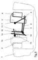
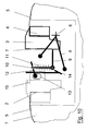
- Figures 1 to 10 show the invention Clamping device in different phases of movement.
- a clamping rail 2 arranged. This extends over the format width of the cylinder 1.
- the end of a printing form serves one across the format width in several sections divided rear clamping rail 3, 4, which is mounted movable overall about a pivot axis 6 is.
- the tensioning rail 3, 4 consists of an upper part 3 and one for picking up and releasing the printing plate end movable lower part 4.
- the rear clamping rail 3, 4 is used to apply a clamping force to the end of the printing form Coupled spring elements, the rear clamping rail 3, 4th by these spring elements, not shown, against the Is pivoted clockwise into the center of the channel.
- a two-armed lever 7, 8 is pivotally mounted.
- the two-armed lever 7, 8 is via adjusting means, not shown actuated. Swiveling the two-armed lever 7, 8 in Clockwise direction causes the correspondingly shaped one End of the lever 7 with the back of the upper part 3 of the rear tensioning rail 3, 4 comes into contact and the rear Tensioning rail 3, 4 so against the spring force to the pressure end channel edge of the forme cylinder 1 is pivoted forward.
- Figure 2 shows that in the front clamping device 2 leading end of a printing plate 5 inserted and clamped has been.
- the trailing end of the printing form 5 is also between lower part 4 and upper part 3 of the rear clamping device attached.
- Figure 3 shows like Figure 2 that completely on the forme cylinder mounted printing form 5, which in the front clamping device 2 and the rear clamping device 3, 4 held is.
- a hand tool designed as a lever is used with a End in a recess 15 of the front clamping device supporting on the top of one of the clamping devices 12 acting so that now via the clamping devices 12 and the associated push rod through the Lever 16 exerted force in a the clamping force of the printing form 5 enlarging swiveling movement of the rear tensioning rail 3, 4 can be implemented.
- Figure 10 shows the completely drawn on the forme cylinder 1 Printing form 5, which at its leading end in the Clamping device 2 and its trailing end in the clamping device 3, 4 is attached.
- the one not shown Spring elements and the rear clamping rail 3, 4 on the Printing form 5 is held securely on the outer circumference of the cylinder 1.
- the two-armed lever 7, 8 stands neither with the tensioning rail 3, after with the contour 14 in Contact, so that by the spring elements, not shown applied clamping force completely on the rear Tensioning rail 3, 4.
Landscapes
- Engineering & Computer Science (AREA)
- Mechanical Engineering (AREA)
- Supply, Installation And Extraction Of Printed Sheets Or Plates (AREA)
- Ink Jet (AREA)
- Dot-Matrix Printers And Others (AREA)
- Silver Salt Photography Or Processing Solution Therefor (AREA)
Abstract
Description
- 1
- Formzylinder
- 2
- Klemmschiene (Druckanfang)
- 3
- Spannschiene Oberteil (Druckende)
- 4
- Spannschiene Unterteil (Druckende
- 5
- Druckform
- 6
- Schwenkachse (hintere Spannschiene 3, 4)
- 7
- Hebelarm
- 8
- Hebelarm
- 9
- Arm
- 10
- Schubstange
- 11
- Feder (Druckfeder)
- 12
- Klemmeinrichtung
- 12.1
- Klemmeinrichtung
- 13
- Langloch
- 14
- Kontur (Klemmeinrichtung 12, 12.1)
Claims (6)
- Spannvorrichtung für einen Druckformzylinder einer Druckmaschine, insbesondere für Lack- oder Druckwerke von Bogenoffsetdruckmaschinen, mit einer beweglich im Zylinderkanal gelagerten und ein Ende einer Druckform aufnehmenden Spannschiene, wobei die auf die Druckform ausgeübte Spannkraft durch der Spannschiene zugeordnete Federelemente erzeugt wird und einer die Spannschiene entgegen dieser Federkraft bewegenden Betätigungseinrichtung sowie einem manuell handhabbaren Werkzeug, mittels dem die Spannschiene zum vergrößern der auf die Druckform ausgeübten Kraft bewegbar ist,
dadurch gekennzeichnet, dass der Spannschiene (3, 4) eine einseitig wirkende Sperrung (10, 12, 12.1) zugeordnet ist, deren Sperrwirkung durch die beim Wechseln einer Druckform aktivierte Betätigungseinrichtung (7, 8) aufhebbar ist. - Spannvorrichtung nach Anspruch 1,
dadurch gekennzeichnet, dass die Sperrung (10, 12, 12.1) als eine an der Spannschiene (3, 4) angelenkte Schubstange (10) ausgebildet ist, welche mit einer zylinderfest abgestützten Klemmeinrichtung (12) zusammenwirkt. - Spannvorrichtung nach Anspruch 2,
dadurch gekennzeichnet, dass der Spannschiene (3, 4) zwei Schubstangen (10) zugeordnet sind, welche mit zwei Klemmvorrichtungen (12, 12.1) zusammenwirken. - Spannvorrichtung nach einem der vorhergehenden Ansprüche,
dadurch gekennzeichnet, dass das manuell handhabbare Werkzeug (16) als ein Hebel ausgebildet ist, welcher über die Sperrung (12, 12.1) auf die hintere Spannschiene (3, 4) einwirkt. - Spannvorrichtung nach einem der vorhergehenden Ansprüche,
dadurch gekennzeichnet, dass die Betätigungseinrichtung (7, 8) als ein zweiarmiger Hebel (7, 8) ausgebildet ist, wobei ein Hebel (7) mit der Spannschiene (3, 4) und der zweite Hebel (8) zum Entsperren der Sperreinrichtung (12, 12.1) zusammenwirkt. - Spannvorrichtung nach Anspruch 5,
dadurch gekennzeichnet, dass mit der Klemmeinrichtung (12, 12.1) eine Kontur (14) gekoppelt ist, welche mit dem Ende des Hebels (8) der Betätigungsvorrichtung zusammenwirkt.
Applications Claiming Priority (2)
| Application Number | Priority Date | Filing Date | Title |
|---|---|---|---|
| DE10151052A DE10151052C1 (de) | 2001-09-26 | 2001-09-26 | Spannvorrichtung für eine Druckform |
| DE10151052 | 2001-09-26 |
Publications (2)
| Publication Number | Publication Date |
|---|---|
| EP1297955A1 true EP1297955A1 (de) | 2003-04-02 |
| EP1297955B1 EP1297955B1 (de) | 2006-07-26 |
Family
ID=7702681
Family Applications (1)
| Application Number | Title | Priority Date | Filing Date |
|---|---|---|---|
| EP02020729A Expired - Lifetime EP1297955B1 (de) | 2001-09-26 | 2002-09-14 | Spannvorrichtung für eine Druckform |
Country Status (3)
| Country | Link |
|---|---|
| EP (1) | EP1297955B1 (de) |
| AT (1) | ATE333995T1 (de) |
| DE (2) | DE10151052C1 (de) |
Citations (2)
| Publication number | Priority date | Publication date | Assignee | Title |
|---|---|---|---|---|
| DE4321751C1 (de) | 1993-06-30 | 1994-11-24 | Roland Man Druckmasch | Vorrichtung zum paßgenauen Spannen von Druckplatten auf dem Plattenzylinder von Druckmaschinen |
| DE19634947C1 (de) | 1996-08-29 | 1998-01-08 | Roland Man Druckmasch | Justiervorrichtung für Druckplatten |
Family Cites Families (2)
| Publication number | Priority date | Publication date | Assignee | Title |
|---|---|---|---|---|
| US2694976A (en) * | 1950-05-29 | 1954-11-23 | Huck Co | Plate lock-up mechanism for printing machines |
| DE4244279C2 (de) * | 1992-12-28 | 1995-05-18 | Heidelberger Druckmasch Ag | Druckformkorrektureinrichtung zum Ausgleich von Druckträgerdehnungen |
-
2001
- 2001-09-26 DE DE10151052A patent/DE10151052C1/de not_active Expired - Fee Related
-
2002
- 2002-09-14 AT AT02020729T patent/ATE333995T1/de active
- 2002-09-14 EP EP02020729A patent/EP1297955B1/de not_active Expired - Lifetime
- 2002-09-14 DE DE50207613T patent/DE50207613D1/de not_active Expired - Lifetime
Patent Citations (2)
| Publication number | Priority date | Publication date | Assignee | Title |
|---|---|---|---|---|
| DE4321751C1 (de) | 1993-06-30 | 1994-11-24 | Roland Man Druckmasch | Vorrichtung zum paßgenauen Spannen von Druckplatten auf dem Plattenzylinder von Druckmaschinen |
| DE19634947C1 (de) | 1996-08-29 | 1998-01-08 | Roland Man Druckmasch | Justiervorrichtung für Druckplatten |
Also Published As
| Publication number | Publication date |
|---|---|
| EP1297955B1 (de) | 2006-07-26 |
| DE50207613D1 (de) | 2006-09-07 |
| ATE333995T1 (de) | 2006-08-15 |
| DE10151052C1 (de) | 2003-02-06 |
Similar Documents
| Publication | Publication Date | Title |
|---|---|---|
| DE69030275T3 (de) | Druckplattenbefestigungsgerät für eine Bogendruckmaschine | |
| EP0812686B1 (de) | Verfahren und Vorrichtung zum Aufbringen einer ebenen Druckplatte auf einen fliegend gelagerten Plattenzylinder einer Druckmaschine | |
| DE3322944A1 (de) | Matrizenauswerfer-vorrichtung fuer mehrstufen-umformmaschinen | |
| EP0238804A2 (de) | Vorrichtung zum Aufspannen von biegsamen Druckplatten auf dem Plattenzylinder von Rotationsdruckmaschinen | |
| DE102009004980A1 (de) | Verfahren zum Positionieren einer Druckplatte auf einem Formzylinder | |
| DE3516682C2 (de) | ||
| EP0736384B1 (de) | Vorrichtung zur Druckan- und -abstellung und Verfahren zum Steuern dieser Vorrichtung | |
| DE69212612T2 (de) | Plattenklemmsystem für eine Vervielfältigungsmaschine | |
| DE4224832C2 (de) | Vorrichtung zur Positionierung eines dem automatischen Druckplattenwechsel dienenden Magazins | |
| DE3409479C2 (de) | ||
| DE4322027A1 (de) | Vorrichtung zum automatischen Wechseln einer Druckplatte | |
| EP1827831B1 (de) | Druckplattenzylinder mit austauschbarer hülse | |
| EP0727311B1 (de) | Vorrichtung zum Wechseln von Druckplatten | |
| DE4321751C1 (de) | Vorrichtung zum paßgenauen Spannen von Druckplatten auf dem Plattenzylinder von Druckmaschinen | |
| EP0144334B1 (de) | Halterung für eine druckplatte | |
| DE202021104908U1 (de) | Nummerierwerk mit variabler Typenradbreite | |
| EP0714768A1 (de) | Druckwerksschaltung | |
| DE10151052C1 (de) | Spannvorrichtung für eine Druckform | |
| EP0425935A2 (de) | Vorrichtung zum parallelen Spannen von Druckplatten | |
| DE19701955C2 (de) | Befestigungsvorrichtung für Druckformen | |
| DE19753820A1 (de) | Vorrichtung zum gegenseitigen Anstellen von Druckwerkzylindern | |
| DE4240333C2 (de) | Einrichtung zum lagegenauen Schnellaufspannen von flexiblen Druckplatten | |
| EP0534214B1 (de) | Verfahren und Vorrichtung zur Korrektur trapezartiger Passerabweichungen | |
| DE4344090A1 (de) | Einrichtung zum automatischen Zu- und Abführen von Druckplatten | |
| DE29506150U1 (de) | Vorrichtung zum Klemmen von Druckplatten |
Legal Events
| Date | Code | Title | Description |
|---|---|---|---|
| PUAI | Public reference made under article 153(3) epc to a published international application that has entered the european phase |
Free format text: ORIGINAL CODE: 0009012 |
|
| 17P | Request for examination filed |
Effective date: 20030131 |
|
| AK | Designated contracting states |
Kind code of ref document: A1 Designated state(s): AT BE BG CH CY CZ DE DK EE ES FI FR GB GR IE IT LI LU MC NL PT SE SK TR |
|
| AX | Request for extension of the european patent |
Extension state: AL LT LV MK RO SI |
|
| AKX | Designation fees paid |
Designated state(s): AT DE FR GB |
|
| GRAP | Despatch of communication of intention to grant a patent |
Free format text: ORIGINAL CODE: EPIDOSNIGR1 |
|
| GRAS | Grant fee paid |
Free format text: ORIGINAL CODE: EPIDOSNIGR3 |
|
| GRAA | (expected) grant |
Free format text: ORIGINAL CODE: 0009210 |
|
| AK | Designated contracting states |
Kind code of ref document: B1 Designated state(s): AT DE FR GB |
|
| PG25 | Lapsed in a contracting state [announced via postgrant information from national office to epo] |
Ref country code: GB Free format text: LAPSE BECAUSE OF FAILURE TO SUBMIT A TRANSLATION OF THE DESCRIPTION OR TO PAY THE FEE WITHIN THE PRESCRIBED TIME-LIMIT Effective date: 20060726 |
|
| REG | Reference to a national code |
Ref country code: GB Ref legal event code: FG4D Free format text: NOT ENGLISH |
|
| REF | Corresponds to: |
Ref document number: 50207613 Country of ref document: DE Date of ref document: 20060907 Kind code of ref document: P |
|
| GBV | Gb: ep patent (uk) treated as always having been void in accordance with gb section 77(7)/1977 [no translation filed] |
Effective date: 20060726 |
|
| EN | Fr: translation not filed | ||
| PLBE | No opposition filed within time limit |
Free format text: ORIGINAL CODE: 0009261 |
|
| STAA | Information on the status of an ep patent application or granted ep patent |
Free format text: STATUS: NO OPPOSITION FILED WITHIN TIME LIMIT |
|
| 26N | No opposition filed |
Effective date: 20070427 |
|
| PG25 | Lapsed in a contracting state [announced via postgrant information from national office to epo] |
Ref country code: FR Free format text: LAPSE BECAUSE OF FAILURE TO SUBMIT A TRANSLATION OF THE DESCRIPTION OR TO PAY THE FEE WITHIN THE PRESCRIBED TIME-LIMIT Effective date: 20070511 |
|
| PG25 | Lapsed in a contracting state [announced via postgrant information from national office to epo] |
Ref country code: FR Free format text: LAPSE BECAUSE OF FAILURE TO SUBMIT A TRANSLATION OF THE DESCRIPTION OR TO PAY THE FEE WITHIN THE PRESCRIBED TIME-LIMIT Effective date: 20060726 |
|
| PGFP | Annual fee paid to national office [announced via postgrant information from national office to epo] |
Ref country code: AT Payment date: 20100914 Year of fee payment: 9 |
|
| PGFP | Annual fee paid to national office [announced via postgrant information from national office to epo] |
Ref country code: DE Payment date: 20110923 Year of fee payment: 10 |
|
| REG | Reference to a national code |
Ref country code: DE Ref legal event code: R081 Ref document number: 50207613 Country of ref document: DE Owner name: MANROLAND SHEETFED GMBH, DE Free format text: FORMER OWNER: MANROLAND AG, 63075 OFFENBACH, DE Effective date: 20120509 |
|
| REG | Reference to a national code |
Ref country code: AT Ref legal event code: MM01 Ref document number: 333995 Country of ref document: AT Kind code of ref document: T Effective date: 20110914 |
|
| PG25 | Lapsed in a contracting state [announced via postgrant information from national office to epo] |
Ref country code: AT Free format text: LAPSE BECAUSE OF NON-PAYMENT OF DUE FEES Effective date: 20110914 |
|
| PG25 | Lapsed in a contracting state [announced via postgrant information from national office to epo] |
Ref country code: DE Free format text: LAPSE BECAUSE OF NON-PAYMENT OF DUE FEES Effective date: 20130403 |
|
| REG | Reference to a national code |
Ref country code: DE Ref legal event code: R119 Ref document number: 50207613 Country of ref document: DE Effective date: 20130403 |