EP1297869A1 - Snow glider, especially a ski and a spreading device for a snow glider - Google Patents
Snow glider, especially a ski and a spreading device for a snow glider Download PDFInfo
- Publication number
- EP1297869A1 EP1297869A1 EP02019847A EP02019847A EP1297869A1 EP 1297869 A1 EP1297869 A1 EP 1297869A1 EP 02019847 A EP02019847 A EP 02019847A EP 02019847 A EP02019847 A EP 02019847A EP 1297869 A1 EP1297869 A1 EP 1297869A1
- Authority
- EP
- European Patent Office
- Prior art keywords
- spreading
- levers
- recess
- expansion
- board body
- Prior art date
- Legal status (The legal status is an assumption and is not a legal conclusion. Google has not performed a legal analysis and makes no representation as to the accuracy of the status listed.)
- Granted
Links
Images


Classifications
-
- A—HUMAN NECESSITIES
- A63—SPORTS; GAMES; AMUSEMENTS
- A63C—SKATES; SKIS; ROLLER SKATES; DESIGN OR LAYOUT OF COURTS, RINKS OR THE LIKE
- A63C5/00—Skis or snowboards
- A63C5/06—Skis or snowboards with special devices thereon, e.g. steering devices
Definitions
- the invention relates to a snow sliding board according to the preamble of claim 1 and according to a spreading device for use with a snow sliding board Preamble of claim 10.
- Snow gliding boards and especially as skis are in a wide variety Executions known. It is also known to use a ski over a partial length with a to be provided from the rear end of the ski in the slot Area of the skis then in width by means of a spreading device provided there is spreadable to thereby u. a. the course of the side edges (sidecut) or their To change the curvature so that with increasing spread an increasing Curvature or waist of the ski results on its long sides.
- the Spreading device is in the known case of two on both sides of the slot on the Top of the ski body attached bearing elements and one across the slot extending adjusting screw formed in a thread of a bearing element is guided and is supported in the other bearing element. By turning the screw in one direction is thus an increasing spread against the inherent elasticity of the Ski body. Turning the screw in the other direction is relieving of the ski body a reduction in the spread possible.
- the object of the present invention is to show a snow sliding board which is characterized by improved, dynamic driving characteristics.
- Task of Invention it is also a spreading device to show that not only one allows effective spreading, but as a complete unit in a gliding board can be installed.
- a snow sliding board is according to the Claim 1 and a spreading device according to claim 10 educated.
- one of the respective loads takes place or deflection of the snow sliding board dependent control of the spread and so that the outer contour (indentation) of the gliding board body takes place, d. H. a dynamic Spread.
- the spreading device according to the invention can be used for dynamic spreading snow sliding board according to the invention are used, but is also quite suitable general for use with spreadable snow gliding boards, also for those where the spreading is not dynamic, but can be adjusted by hand.
- an adapter or control element e.g. Elements guided in guides on the snow sliding board and are fixed in one area on the snow sliding board and in another, in The longitudinal direction of the snow gliding board drives the area to the drive Spreading device or a spreading element of this device act.
- 1 generally designates a ski (alpine ski), the ski body of which 2 is manufactured using the usual ski building materials and technologies.
- Attachment plate 5 attached, for example with the help of a system (z. B. Rail system), which is a fixed or substantially fixed location of the Binding plate 5 guaranteed between the two ends 3 and 4, but at the same time a uniform bending line of the ski body 2 when loaded, for example when Driving through hollows in the terrain, also in the area of the binding plate 5 guaranteed.
- z. B. Rail system z. B. Rail system
- the front and rear binding element are attached, which in Figures 1 and 2 are indicated schematically with 6 and 7.
- the ski body 2 is in an area 2 ', which extends in the longitudinal direction L of the ski body starting from the end 4 in the direction
- Binding plate 5 extends, but ends at a distance from this binding plate, slit wedge-shaped, d. H. with a recess 8 open towards this end 4 provided, which is axially aligned with the longitudinal axis L of the ski body 2 and itself in the illustrated embodiment, starting from its side open at the end 4 in Tapered towards the center of the ski body or binding plate 5.
- the Recess 8 forms edges 8 'and at its closed end a circular Extension 8 ", the diameter of which is greater than the distance that the edges 8 'at Have transition to the extension 8 'from each other.
- a spreading device 9 is arranged in the recess 8, with which the ski body 2 in its section 2 'or with those formed on both sides by the recess 8 Edge areas 10 against the inherent elasticity of the material of the ski body 2 or the Edge regions 10 can be spread in the transverse direction of the ski body, as is the case in FIG Figure 3 is indicated by the arrows A.
- edge lines 11 sidecut of the ski body 2
- the course of the long sides having the steel edges is or edge lines 11 (sidecut) of the ski body 2 can be changed, namely between one "normal” course or a normal curvature that the edge lines 11 at have spread ski body section 2 ', and courses in which at more or less spread ski body section 2 'the edge lines 11 and thus the Outer contour (indentation) have a course with a greater curvature.
- a control or coupling connection 12 which is shown in the Embodiment essentially of one, preferably adjustable in length Rod 13 is formed, the spreader 9 with the rear end of the Binding plate 5 connected, namely via a ball joint 14 on the binding plate 5 and a ball joint 15 on the spreader 9.
- the rod 13 is in a Longitudinal axis L including the central plane of the ski body 2 at a distance above the Top of the ski body, so that when the ski body 2 is bent from the one shown in FIG shown state in the state shown in Figure 2 via the Control connection 12 a movement to that connected to the spreading device 9 Ball joint 15 is exercised, and that according to the arrow B in the direction the end of the ski 4.
- the spreading device 9 and its functional elements are shown in more detail in FIGS. 3-9 presented in detail.
- the spreading device 9 is in the illustrated Embodiment of a frame member 16 which is essentially bracket or is formed like a bracket, with two substantially straight Legs or frame sections 17, which have a rounded frame section 18 are connected at one end.
- the frame element 16 is in one piece made of a material with sufficient elasticity and strength, e.g. out Plastic.
- the frame sections 17 and 18 are, for example, Z-shaped in cross section executed that they the ski body 2 at least on the edge 8 'of the recess 8 and cover along the edge 8 'also at the top and recess 8 up to also close a gap 19 towards the underside of the ski.
- the round frame section 18 is from the extension 8 "of the recess 8 added.
- the frame sections 17 and 18 form an approximately Z profile in cross section, as shown in Figure 9 for the frame sections 17, with the leg 17 'resting against the top of the ski body 2, with the limb 17' thereon adjoining, the edge 8 'covering leg 17 "and with it adjoining legs 17 '' running parallel to the underside 20 of the ski body.
- the frame portions 17 form between their legs 17 '"the slot 19, the is closed by a plate 21 resting on the leg 17 "'.
- the plate 21 is part of an expansion element 22 which extends in the direction of the longitudinal axis L. predetermined expansion stroke SH in that formed by the legs 17 "and 17" ' Space is slidably provided.
- the expansion element 22 also includes one the spreading lever arrangement 23 fastened to the plate 21 with a connecting piece 24, which is connected to the plate 21 and with its longitudinal extension in the Longitudinal axis L lies, and has a plurality of spreading levers 25. These are with an inner end are hinged to the connecting element 24 via film hinges and stand over both sides of the connecting element 24 or the expansion element 22 gone.
- Each spreader lever 25 has a free end on a frame section 17 articulated so that when the expansion element 22 is moved, it spreads apart the frame sections 17 and thus the spreading of the edge regions 10 of the ski body 2 is done.
- the expansion element 22, which on the top of the ski by a Cover plate 26 is covered, has on its closer to the binding plate 5 End on a coupling section, which is generally designated 27 in the figures and to which the ball joint 15 is attached.
- the spreading levers 25 each form pairs of spreading levers, each with two spreading levers 25, each of which protrudes over a longitudinal side of the expansion element 22. I'm not spread state form the spreading lever 25 of each pair of spreading levers with their Longitudinal axis an angle less than 180 °, which extends to the free ends of the Frame sections 17 opens.
- a knob 28 with an eccentric control surface is rotatable to the underside 20 of the ski 28 'is provided, which with the frame section 18 adjacent end 29 of the Spreading element 22 cooperates, in such a way that when removed Control connection 12 by turning the knob 28 and moving the Spreading element 22 different spreading states of the ski body section 2 ' can be set, in contrast to the dynamic described above, i.e. a spread dependent on the deflection of the ski body 2 Spread is reached.
- the spreading lever 25 for example by different angular position and / or length of these levers can be the characteristic of the spreading of the ski or the deformation of the outer contour of the ski (retraction) become.
- FIG. 10 shows a ski 1a in a very simplified representation and in section, whose ski body 2a in turn in a ski body section starting from the rear end in the direction of the binding area or one there Binding plate is slotted, with a slot 30 which is at the top of the Ski body 2a in a trough-like, extending in the longitudinal direction of the ski body Recess 31 with a larger width merges.
- the slot is at the two edges 30 ' 30 each provided with a groove 32 open towards this edge, which is in The longitudinal direction of the ski body 2a extends at least over a partial length of the slot 30 extends.
- the slot 30 and in the groove-shaped recesses 32 engages as Wedge-shaped or acting expansion element 33, which is part of the Spreading device 9a and in the longitudinal direction of the ski body 2a by a certain Amount is shiftable.
- the ball joint 15 is for the Control connection 12 is provided, with which the expansion element 33 in turn with the Binding plate 5 is connected.
- the slot 30 with the grooves 32 is in at least a wedge-shaped portion. Basically there is also the possibility that the slot 30 is straight and the grooves 32 in at least one Partial area are wedge-shaped.
- At least one adapter or control element offset from the bending line of the ski is provided on this, which on a Area is fixed on the ski body and at least on another, in the longitudinal direction of the Skis staggered and guided in guides in the longitudinal direction of the ski is drivingly connected to the expansion element of the respective expansion device.
- the adapter or control element is, for example, part of a binding plate or provided outside the area for attachment of the binding so that basically every binding can be mounted on the ski without one Adjustment between binding and spreader is necessary.
- ski body instead of or in addition to this, slit in a front area and to provide at least one spreader there, or over the ski body to slit its entire or almost entire length and in the area of this To provide slot with at least one spreading device.
Landscapes
- Footwear And Its Accessory, Manufacturing Method And Apparatuses (AREA)
- Road Paving Structures (AREA)
- Organic Low-Molecular-Weight Compounds And Preparation Thereof (AREA)
Abstract
Description
Die Erfindung bezieht sich auf ein Schneegleitbrett gemäß Oberbegriff Patentanspruch
1 und auf eine Spreizvorrichtung zur Verwendung bei einem Schneegleitbrett gemäß
Oberbegriff Patentanspruch 10.The invention relates to a snow sliding board according to the preamble of claim
1 and according to a spreading device for use with a snow sliding board
Preamble of
Schneegleitbretter und insbesondere auch als Ski sind in unterschiedlichsten Ausführungen bekannt. Bekannt ist weiterhin, einen Ski über eine Teillänge mit einem von dem rückwärtigen Ende des Skis ausgehenden Schlitz zu versehen, in dessen Bereich der Ski dann mittels einer dort vorgesehene Spreizvorrichtung in seiner Breite spreizbar ist, um hierdurch u. a. den Verlauf der Seitenkanten (Sidecut) bzw. deren Krümmung so zu verändern, daß sich mit zunehmender Spreizung eine zunehmende Krümmung oder Taillierung des Skis an seinen Längsseiten ergibt. Die Spreizvorrichtung ist im bekannten Fall von zwei beidseitig vom Schlitz auf der Oberseite des Skikörpers befestigten Lagerelementen und einer quer zum Schlitz verlaufenden Stellschraube gebildet, die in einem Gewinde eines Lagerelementes geführt ist und sich im anderen Lagerelement abstützt. Durch Drehen der Schraube in der einen Richtung ist somit ein zunehmendes Spreizen gegen die Eigenelastizität des Skikörpers. Durch Drehen der Schraube in der anderen Richtung ist durch Entlasten des Skikörpers eine Reduzierung der Spreizung möglich.Snow gliding boards and especially as skis are in a wide variety Executions known. It is also known to use a ski over a partial length with a to be provided from the rear end of the ski in the slot Area of the skis then in width by means of a spreading device provided there is spreadable to thereby u. a. the course of the side edges (sidecut) or their To change the curvature so that with increasing spread an increasing Curvature or waist of the ski results on its long sides. The Spreading device is in the known case of two on both sides of the slot on the Top of the ski body attached bearing elements and one across the slot extending adjusting screw formed in a thread of a bearing element is guided and is supported in the other bearing element. By turning the screw in one direction is thus an increasing spread against the inherent elasticity of the Ski body. Turning the screw in the other direction is relieving of the ski body a reduction in the spread possible.
Aufgabe der vorliegenden Erfindung ist es, ein Schneegleitbrett aufzuzeigen, welches sich durch verbesserte, dynamische Fahreigenschaften auszeichnet. Aufgabe der Erfindung ist es weiterhin eine Spreizvorrichtung aufzuzeigen, die nicht nur ein wirksames Spreizen ermöglicht, sondern als komplette Baueinheit in ein Gleitbrett einbaubar ist. Zur Lösung dieser Aufgabe ist ein Schneegleitbrett entsprechend dem Patentanspruch 1 und eine Spreizvorrichtung entsprechend dem Patentanspruch 10 ausgebildet.The object of the present invention is to show a snow sliding board which is characterized by improved, dynamic driving characteristics. Task of Invention, it is also a spreading device to show that not only one allows effective spreading, but as a complete unit in a gliding board can be installed. To solve this task, a snow sliding board is according to the Claim 1 and a spreading device according to claim 10 educated.
Bei dem erfindungsgemäßen Schneegleitbrett findet eine von der jeweiligen Belastung oder Durchbiegung des Schneegleitbrettes abhängige Steuerung der Spreizung und damit der Außenkontur (Einzug) des Gleitbrettkörpers statt, d. h. ein dynamisches Spreizen.In the snow sliding board according to the invention one of the respective loads takes place or deflection of the snow sliding board dependent control of the spread and so that the outer contour (indentation) of the gliding board body takes place, d. H. a dynamic Spread.
Die erfindungsgemäße Spreizvorrichtung kann für das dynamische Spreizen bei dem erfindungsgemäßen Schneegleitbrett verwendet werden, eignet sich aber auch ganz allgemein für die Verwendung bei spreizbaren Schneegleitbrettern, auch bei solchen, bei denen das Spreizen nicht dynamisch erfolgt, sondern von Hand einstellbar ist.The spreading device according to the invention can be used for dynamic spreading snow sliding board according to the invention are used, but is also quite suitable general for use with spreadable snow gliding boards, also for those where the spreading is not dynamic, but can be adjusted by hand.
Das dynamische bzw. progressive Spreizen des Schneegleitbretts und damit das dynamische Verformen der Außenkontur (Einzug) des Schneegleitbretts erfolgt bei der Erfindung also durch die Längendifferenz der Biegelinie des Schneegleitbretts und einer versetzten Biegelinie oder einer Strecke, beispielsweise eines Adapters oder eines anderen Steuerelementes, welches auch integrierter Bestandteil des Schneegleitbretts sein kann oder aber an diesem montiert ist. Als Adapter oder Steuerelement eignen sich beispielsweise u.a. Elemente, die auf dem Schneegleitbrett in Führungen geführt und an einem Bereich am Schneegleitbrett fixiert sind sowie an einem weiteren, in Längsrichtung des Schneegleitbrettes versetzten Bereich antriebsmäßig auf die Spreizvorrichtung oder ein Spreizelement dieser Vorrichtung einwirken.The dynamic or progressive spreading of the snow sliding board and thus that dynamic deformation of the outer contour (retraction) of the snow sliding board takes place at the Invention by the length difference of the bending line of the snow sliding board and an offset bending line or a line, for example an adapter or one other control element, which is also an integral part of the snow sliding board can be or is mounted on this. Suitable as an adapter or control element e.g. Elements guided in guides on the snow sliding board and are fixed in one area on the snow sliding board and in another, in The longitudinal direction of the snow gliding board drives the area to the drive Spreading device or a spreading element of this device act.
Weiterbildungen der Erfindung sind Gegenstand der Unteransprüche. Die Erfindung
wird im folgenden anhand der Figuren an einem Ausführungsbeispiel näher erläutert.
Es zeigen:
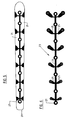
- Fig. 1 und 2
- in sehr vereinfachter Darstellung einen Ski in Seitenansicht im entspannten Zustand (Figur 1) und im gespannten Zustand (Figur 2);
- Fig. 3
- in Teildarstellung eine Draufsicht auf ein hinteres Ende des Skis der Figuren 1 und 2, zusammen mit einer möglichen Ausführungsform einer im Skikörper vorgesehenen Spreizvorrichtung;
- Fig. 4
- eine Darstellung
ähnlich Figur 3, jedoch bei demontierter Spreizvorrichtung; - Fig. 5 - 8
- Elemente der Spreizvorrichtung in Einzeldarstellung und in Draufsicht;
- Fig. 9
- in vereinfachter Darstellung einen Querschnitt durch einen Ski der Figuren 1 - 4
entsprechend der Linie I - I der
Figur 3; - Fig. 10
- in vereinfachter Darstellung einen Querschnitt durch einen Ski bei einer weiteren Ausführungsform der Erfindung.
Show it:
- 1 and 2
- in a very simplified representation a ski in side view in the relaxed state (Figure 1) and in the tensioned state (Figure 2);
- Fig. 3
- in partial representation a plan view of a rear end of the ski of Figures 1 and 2, together with a possible embodiment of a spreading device provided in the ski body;
- Fig. 4
- a representation similar to Figure 3, but with the spreading device removed;
- 5 - 8
- Elements of the spreading device in individual representation and in plan view;
- Fig. 9
- in a simplified representation a cross section through a ski of Figures 1-4 along the line I - I of Figure 3;
- Fig. 10
- in a simplified representation a cross section through a ski in a further embodiment of the invention.
In den Figuren 1 - 9 ist mit 1 allgemein ein Ski (Alpinski) bezeichnet, dessen Skikörper
2 unter Verwendung der üblichen Skibaumaterialien und Technologien hergestellt ist.
In der Mitte des Skis, d. h. zwischen dem vorderen, die Schaufel bildenden Skiende 3
und dem rückwärtigen Skiende 4 ist auf der Oberseite des Skikörpers 2 eine
Bindungsplatte 5 befestigt, und zwar beispielsweise mit Hilfe eines Systems (z. B. Rail-Systems),
welches eine ortsfeste oder im wesentlichen ortsfeste Lage der
Bindungsplatte 5 zwischen den beiden Enden 3 und 4 gewährleistet, zugleich aber
eine gleichmäßige Biegelinie des Skiskörpers 2 beim Belasten, beispielsweise beim
Durchfahren von Mulden im Gelände, auch im Bereich der Bindungsplatte 5
gewährleistet. Derartige Befestigungssysteme sind dem Fachmann bekannt. Auf der
Bindungsplatte 5 sind das vordere und rückwärtige Bindungselement befestigt, die in
den Figuren 1 und 2 schematisch mit 6 und 7 angedeutet sind.1 to 9, 1 generally designates a ski (alpine ski), the ski body of which
2 is manufactured using the usual ski building materials and technologies.
In the middle of the ski, i.e. H. between the front ski end forming the
Wie insbesondere die Figuren 3 und 4 zeigen, ist der Skikörper 2 in einem Bereich 2',
der sich in Skikörperlängsrichtung L ausgehend von dem Ende 4 in Richtung
Bindungsplatte 5 erstreckt, allerdings mit Abstand von dieser Bindungsplatte endet,
keilförmig geschlitzt, d. h. mit einer zu diesem Ende 4 hin offenen Ausnehmung 8
versehen, die achsgleich mit der Längsachse L des Skikörpers 2 ausgebildet ist und sich
bei der dargestellten Ausführungsform ausgehend von ihrer am Ende 4 offenen Seite in
Richtung Skikörpermitte bzw. Bindungsplatte 5 hin keilförmig verengt. Die
Ausnehmung 8 bildet Ränder 8' sowie an ihrem geschlossenen Ende eine kreisrunde
Erweiterung 8", deren Durchmesser größer ist als der Abstand, den die Ränder 8' am
Übergang zu der Erweiterung 8' voneinander besitzen.As in particular FIGS. 3 and 4 show, the
In der Ausnehmung 8 ist eine Spreizvorrichtung 9 angeordnet, mit der der Skikörper 2
in seinem Abschnitt 2' bzw. mit den beidseitig von der Ausnehmung 8 gebildeten
Randbereichen 10 gegen die Eigenelastizität des Materials des Skikörpers 2 bzw. der
Randbereiche 10 in Skikörperquerrichtung gespreizt werden kann, wie dies in der
Figur 3 mit den Pfeilen A angedeutet ist.A spreading
Durch dieses Spreizen ist der Verlauf der die Stahlkanten aufweisenden Längsseiten
oder Randlinien 11 (Sidecut) des Skikörpers 2 veränderbar, und zwar zwischen einem
"normalen" Verlauf oder einer normalen Krümmung, die die Randlinien 11 bei nicht
gespreiztem Skikörperabschnitt 2' aufweisen, und Verläufen, in denen bei mehr oder
weniger gespreiztem Skikörperabschnitt 2' die Randlinien 11 und damit die
Außenkontur (Einzug) einen Verlauf mit einer stärkeren Krümmung besitzen. Der
Aufbau dieser Spreizvorrichtung 9 wird nachstehend noch näher beschrieben.As a result of this spreading, the course of the long sides having the steel edges is
or edge lines 11 (sidecut) of the
Über eine Steuer- oder Koppelverbindung 12, die bei der dargestellten
Ausführungsform im wesentlichen von einer, vorzugsweise in ihrer Länge einstellbaren
Stange 13 gebildet ist, ist die Spreizvorrichtung 9 mit dem rückwärtigen Ende der
Bindungsplatte 5 verbunden, und zwar über ein Kugelgelenk 14 an der Bindungsplatte
5 und ein Kugelgelenk 15 an der Spreizvorrichtung 9. Die Stange 13 liegt in einer die
Längsachse L einschließenden Mittelebene des Skikörpers 2 mit Abstand über der
Oberseite des Skikörpers, so daß beim Biegen des Skiskörpers 2 aus dem in der Figur 1
dargestellten Zustand in den in der Figur 2 wiedergegebenen Zustand über die
Steuerverbindung 12 eine Bewegung auf das mit der Spreizvorrichtung 9 verbundene
Kugelgelenk 15 ausgeübt wird, und zwar entsprechend dem Pfeil B in Richtung zu
dem Skiende 4 hin. Hierdurch erfolgt in Abhängigkeit von dem Grad der
Durchbiegung des Skikörpers 2 eine Steuerung der Spreizvorrichtung 9 und damit bei
der dargestellten Ausführungsform ein mit dem Grad der Durchbiegung des Skis 1
bzw. des Skikörpers 2 zunehmendes Spreizen des Skikörperabschnittes 2' sowie ein
zunehmendes Krümmen der Randlinien 11.Via a control or
Die Spreizvorrichtung 9 und deren Funktionselemente sind in den Figuren 3 - 9 näher
im Detail dargestellt. Die Spreizvorrichtung 9 besteht bei der dargestellten
Ausführungsform aus einem Rahmenelement 16, welches im wesentlichen bügel- oder
klammerartig ausgebildet ist, und zwar mit zwei im wesentlichen geradlinigen
Schenkeln oder Rahmenabschnitten 17, die über einen abgerundeten Rahmenabschnitt
18 an einem Ende miteinander verbunden sind. Das Rahmenelement 16 ist einstückig
aus eine Material mit ausreichender Elastizität und Festigkeit hergestellt, z.B. aus
Kunststoff.The spreading
Die Rahmenabschnitte 17 und 18 sind im Querschnitt beispielsweise Z-förmig so
ausgeführt, daß sie den Skikörper 2 zumindest am Rand 8' der Ausnehmung 8 und
entlang des Randes 8' auch an der Oberseite abdecken und Ausnehmung 8 bis auf
einen Spalt 19 auch zur Skiunterseite hin verschließen.The
Der runde Rahmenabschnitt 18 ist von der Erweiterung 8" der Ausnehmung 8
aufgenommen. Die Rahmenabschnitte 17 und 18 bilden im Querschnitt ein in etwa Z-Profil,
wie dies in der Figur 9 für die Rahmenabschnitte 17 dargestellt ist, und zwar mit
dem gegen die Oberseite des Skikörpers 2 anliegenden Schenkel 17', mit dem daran
anschließenden, den Rand 8' abdeckenden Schenkel 17" und mit dem daran
anschließenden, parallel zur Unterseite 20 des Skikörpers verlaufenden Schenkel 17"'.The
Die Rahmenabschnitte 17 bilden zwischen ihren Schenkeln 17'" den Schlitz 19, der
durch eine auf den Schenkel 17"' aufliegende Platte 21 verschlossen ist. Die Platte 21
ist Teil eines Spreizelementes 22, welches in Richtung der Längsachse L um einen
vorgegebenen Spreizhub SH in dem von den Schenkeln 17" und 17"' gebildeten
Raum verschiebbar vorgesehen ist. Das Spreizelementes 22 umfaßt außerdem eine an
der Platte 21 befestigte Spreizhebelanordnung 23 mit einem Verbindungsstück 24,
welches mit der Platte 21 verbunden ist und mit seiner Längserstreckung in der
Längsachse L liegt, sowie eine Vielzahl von Spreizhebeln 25 aufweist. Diese sind mit
einem inneren Ende am Verbindungselement 24 über Filmscharniere angelenkt sind
und stehen über beide Seiten des Verbindungselementes 24 bzw. des Spreizelementes
22 weg. The
Jeder Spreizhebel 25 ist mit seinem freien Ende an einem Rahmenabschnitt 17
angelenkt, so daß beim Verschieben des Spreizelementes 22 ein Auseinanderspreizen
der Rahmenabschnitte 17 und damit das Spreizen der Randbereiche 10 des Skikörpers
2 erfolgt. Das Spreizelement 22, welches an der Oberseite des Skis durch eine
Abdeckplatte 26 abgedeckt ist, weist an seinem der Bindungsplatte 5 näher liegenden
Ende einen Kupplungsabschnitt auf, der in den Figuren allgemein mit 27 bezeichnet ist
und an dem das Kugelgelenk 15 befestigt ist.Each
Die Spreizhebel 25 bilden jeweils Spreizhebelpaare mit jeweils zwei Spreizhebeln 25,
von denen jeder über eine Längsseite des Spreizelementes 22 vorsteht. Im nicht
gespreizten Zustand bilden die Spreizhebel 25 jedes Spreizhebelpaares mit ihrer
Längsachse einen Winkel kleiner als 180°, der sich zu den freien Enden der
Rahmenabschnitte 17 hin öffnet. Im Rahmenabschnitt 17 ist um eine Achse senkrecht
zur Skiunterseite 20 drehbar ein Drehknopf 28 mit einer exzenterartigen Steuerfläche
28' vorgesehen, die mit dem dem Rahmenabschnitt 18 benachbarten Ende 29 des
Spreizelementes 22 zusammenwirkt, und zwar in der Weise, daß bei entfernter
Steuerverbindung 12 durch Drehen des Drehknopfes 28 und durch Verschieben des
Spreizelementes 22 unterschiedliche Spreizzustände des Skikörperabschnitts 2'
eingestellt werden können, also im Gegensatz zu dem vorbeschriebenen dynamischen,
d.h. von der Durchbiegung des Skikörpers 2 abhängigen Spreizung eine statische
Spreizung erreicht wird.The spreading levers 25 each form pairs of spreading levers, each with two spreading
Durch unterschiedliche Auslegung der Spreizhebel 25, beispielsweise durch
unterschiedliche Winkelstellung und/oder Länge dieser Hebel kann die Charakteristik
des Spreizens des Skis bzw. des Verformens der Ski-Außenkontur (Einzug) beeinflußt
werden.By different design of the spreading
Die Figur 10 zeigt in sehr vereinfachter Darstellung und im Schnitt einen Ski 1a,
dessen Skikörper 2a wiederum in einem Skikörperabschnitt ausgehend von dem
rückwärtigen Ende in Richtung des Bindungsbereiches oder einer dortigen
Bindungsplatte geschlitzt ist, und zwar mit einem Schlitz 30, der an der Oberseite des
Skikörpers 2a in eine muldenartige, sich in Längsrichtung des Skikörpers erstreckende
Vertiefung 31 mit größerer Breite übergeht. An den beiden Rändern 30' ist der Schlitz
30 jeweils mit einer zu diesem Rand hin offenen Nut 32 versehen, die sich in
Längsrichtung des Skikörpers 2a sich zumindest über eine Teillänge des Schlitzes 30
erstreckt. In den Schlitz 30 sowie in die nutenförmigen Ausnehmungen 32 greift ein als
Keil ausgebildetes oder wirkendes Spreizelement 33 ein, das Bestandteil der
Spreizvorrichtung 9a ist und in Längsrichtung des Skikörpers 2a um einen bestimmten
Betrag verschiebbar ist. An dem Spreizelement 33 ist das Kugelgelenk 15 für die
Steuerverbindung 12 vorgesehen, mit der das Spreizelement 33 wiederum mit der
Bindungsplatte 5 verbunden ist. Der Schlitz 30 mit den Nuten 32 ist in wenigstens
einem Teilbereich keilförmig ausgebildet. Grundsätzlich besteht auch die Möglichkeit,
daß der Schlitz 30 geradlinig ausgeführt und die Nuten 32 in wenigstens einem
Teilbereich keilförmig ausgebildet sind.FIG. 10 shows a
Die Erfindung wurde voranstehend an Ausführungsbeispielen beschrieben. Es versteht sich, daß zahlreiche weitere Änderungen sowie Abwandlungen möglich sind, ohne daß dadurch der der Erfindung zugrundeliegende Erfindungsgedanke verlassen wird.The invention has been described above using exemplary embodiments. It understands realize that numerous other changes and modifications are possible without that this leaves the inventive idea on which the invention is based.
So wurde vorstehend davon ausgegangen, daß bei der dynamischen Steuerung des
Verlaufs der Randlinien 11 Skikörpers 3 die Spreizvorrichtung 9 bzw. 9a über eine
eine Stange aufweisende Steuerverbindung 12 gesteuert wird. Selbstverständlich sind
auch andere Verbindungen denkbar. Weiterhin wurde vorstehend davon ausgegangen,
daß die Steuerung der Spreizvorrichtung 9 bzw. 9a über die Bindungsplatte 5 erfolgt.
Selbstverständlich besteht auch die Möglichkeit, die Steuerverbindung 12 zu der
jeweiligen Spreizvorrichtung 9 bzw. 9a mit einem Bindungselement, beispielsweise
mit dem Bindungselement 7 herzustellen.It was previously assumed that the dynamic control of the
Course of the edge lines 11 of the
Vorstehend wurde weiterhin davon ausgegangen, daß mit zunehmender Durchbiegung
des Skikörpers 2 bzw. 2a ein zunehmendes Spreizen des spreizbaren
Skikörperabschnitts 2' erfolgt. Selbstverständlich sind bei entsprechender Ausbildung
der Spreizvorrichtung auch andere Spreizcharakteristiken denkbar, beispielsweise
umgekehrt ein maximales Spreizen bei entlastetem Ski und ein Abnehmen des
Spreizens mit zunehmender Belastung des Skis.Above it was further assumed that with increasing deflection
of the
Vorstehend wurde davon ausgegangen, daß die Steuerung der jeweiligen
Spreizvorrichtung 9 bzw. 9a über eine Koppel bzw. Steuerverbindung erfolgt, und
zwar durch die Längendifferenz zwischen der Länge der Koppelstange 13 und der
Biegelinie des Skis 1 bzw. 1a beim Durchbiegen. Selbstverständlich sind auch andere
Maßnahmen denkbar, die aufgrund der Längendifferenz zwischen der Biegelinie des
Skis und einer gegenüber dieser Biegelinie radial versetzten weiteren Biegelinie oder
Strecke die dynamische Steuerung der jeweiligen Spreizvorrichtung bewirken.
Insbesondere ist es auch möglich, wenigstens ein Adapter- oder Steuerelement
gegenüber der Biegelinie des Skis versetzt an diesem vorzusehen, welches an einem
Bereich am Skikörper fixiert ist und zumindest an einem anderen, in Längsrichtung des
Skis versetzten Bereich in Führungen in Skilängsrichtung beweglich geführt und
antriebsmäßig mit dem Spreizelement der jeweiligen Spreizvorrichtung verbunden ist.
Das Adapter- oder Steuerelement ist beispielsweise Teil einer Bindungsplatte oder
außerhalb des Bereichs für die Befestigung der Bindung vorgesehen, so daß
grundsätzlich jede Bindung auf dem Ski montiert werden kann, ohne daß eine
Anpassung zwischen Bindung und Spreizvorrichtung notwendig ist. Bei der
vorstehenden Beschreibung mögliche Ausführungen der Erfindung wurde davon
ausgegangen, daß der jeweilige Ski 1 bzw. 1a im rückwärtigen Bereich über eine
Teillänge geschlitzt ist. Selbstverständlich besteht auch die Möglichkeit, den Skikörper
anstelle hiervon oder zusätzlich hierzu in einem vorderen Bereich zu schlitzen und
dort wenigstens eine Spreizvorrichtung vorzusehen, oder aber den Skikörper über
seine gesamte oder nahezu gesamte Länge zu schlitzen und im Bereich dieses
Schlitzes mit wenigstens einer Spreizvorrichtung zu versehen. It was assumed above that the control of the respective
Spreading
- 1, 1a1, 1a
- Skiski
- 2, 2a2, 2a
- Skikörperski body
- 2'2 '
- spreizbarer Skikörperabschnittexpandable ski body section
- 3, 43, 4
- Skikörperendeski body
- 55
- Bindungsplattebinding plate
- 6, 76, 7
- Bindungselementbinding element
- 88th
- Schlitz oder Ausnehmung im SkikörperSlit or recess in the ski body
- 8'8th'
- Randedge
- 8"8th"
- Verlängerungrenewal
- 9, 9a9, 9a
- Spreizvorrichtungspreading
- 1010
- Randbereichborder area
- 1111
- Randlinie (Sidecut)Borderline (Sidecut)
- 1212
- Steuerverbindungcontrol connection
- 1313
- Koppelstangecoupling rod
- 14, 1514, 15
- Kugelgelenkball joint
- 1616
- Rahmenelementframe element
- 17,1817.18
- Rahmenabschnittframe section
- 17', 17", 17"'17 ', 17 ", 17"'
- Schenkelleg
- 1919
- Schlitzslot
- 2020
- Skiunterseiteski base
- 2121
- Platteplate
- 2222
- Spreizelementspreader
- 2323
- Hebelelementlever member
- 2424
- Verbindungsstückjoint
- 2525
- Spreizhebelspreading lever
- 2626
- Abschlußplatteend plate
- 2727
- Kopplungsabschnittcoupling portion
- 2828
- Drehknopf knob
- 28'28 '
- Steuerkurvecam
- 2929
- EndeThe End
- 3030
- Schlitzslot
- 3131
- Vertiefungdeepening
- 3232
- Nutgroove
- 3333
- Spreizelementspreader
- AA
- Spreizbewegungspreading
- BB
- Steuerbewegungcontrol movement
- LL
- Längsachselongitudinal axis
- SHSH
- SpreizhubSpreizhub
Claims (14)
und/oder
daß im Gleitbrettkörper (2, 2a) in einer Längsrichtung (L) dieses Körpers gegenüber einem Bindungsbereich (5) versetzt wenigstens ein spreizbarer Abschnitt (2') vorgesehen ist.Snow gliding board according to claim 1, characterized in that the gliding board body (2, 2a) is provided on the partial length (2 ') with at least one slit or slot-like opening (8, 30) and the spreading device (9, 9a) is a spreading of the gliding board body (2, 2a) in the area of this slot or on edge areas (10) formed between the at least one slot (8, 30) and long sides of the sliding board body,
and or
that at least one expandable section (2 ') is provided in the sliding board body (2, 2a) in a longitudinal direction (L) of this body in relation to a binding region (5).
wobei beispielsweise
die Spreizvorrichtung (9, 9a) bzw. dessen Spreizelement (22, 33) über eine Zugund/oder Schubkräfte übertragende Koppel (12), vorzugsweise über eine Koppelstange (13), die an einem Koppel- oder Verbindungspunkt (15) der Spreizvorrichtung (9, 9a) angreift, mit einem weiteren, in einer Längsrichtung des Gleitbrettkörpers (2, 2a) versetzten Angriffs- oder Koppelpunkt (14) verbunden ist und wenigstens einer dieser Koppelpunkte gegenüber der Biegelinie des Gleitbrettkörpers (2, 2a) in Bezug auf deren Biegeachse radial versetzt ist.Snow gliding board according to one of the preceding claims, characterized in that the spreading device (9, 9a) or a spreading element (22, 33) of the spreading device causing the spreading is actuated via a control or an adapter, specifically because of the length difference between the bending line of the Sliding board body (2, 2a) and a radially offset distance or further bending line,
being for example
the spreading device (9, 9a) or its spreading element (22, 33) via a coupling (12) transmitting tensile and / or thrust forces, preferably via a coupling rod (13), which is connected to a coupling or connection point (15) of the spreading device (9 , 9a), is connected to a further engagement or coupling point (14) offset in a longitudinal direction of the sliding board body (2, 2a) and at least one of these coupling points is radial with respect to the bending line of the sliding board body (2, 2a) with respect to the bending axis thereof is offset.
gemeinsamen, in Längsrichtung der Ausnehmung oder des Schlitzes (8) zum Spreizen verschiebbaren Träger (23) schwenkbar vorgesehen und mit außen liegenden Enden an einem am Rand (8') der Ausnehmung (8) vorgesehenen oder gebildeten Lager (17) angelenkt sind, und daß die Spreizhebel (25), die mit ihrer Längserstreckung einen Winkel miteinander einschließen, beim Betätigen der Spreizvorrichtung (9) im Sinne einer Verkleinerung und/oder Vergrößerung dieses Winkels schwenkbar sind,
wobei beispielsweise die Längserstreckung der Ausnehmung (8) die Winkelhalbierende des zwischen den beiden Spreizhebeln (25) gebildeten Winkels ist, und/oder
wobei beispielsweise mehrere, jeweils zwei Spreizhebel (25) aufweisende Spreizhebelpaare vorgesehen sind.Snow gliding board according to one of the preceding claims, characterized in that the spreading element (22) of the spreading device (9) has at least two spreading levers (25) which have an inner end on one
common, in the longitudinal direction of the recess or the slot (8) slidable for spreading support (23) provided and articulated with outer ends on a at the edge (8 ') of the recess (8) provided or formed bearing (17), and that the expansion levers (25), which form an angle with one another with their longitudinal extension, can be pivoted when the expansion device (9) is actuated in the sense of a reduction and / or enlargement of this angle,
where, for example, the longitudinal extent of the recess (8) is the bisector of the angle formed between the two spreading levers (25), and / or
wherein, for example, several pairs of spreading levers (25) each are provided.
und/oder
daß das Spreizelement (33) der Spreizvorrichtung (9a) um wenigstens einen Spreizhub in eine Achsrichtung, vorzugsweise in Richtung der Längsachse des Gleitbrettkörpers verschiebbar ist und am Spreizelement (33) und/oder am Gleitbrettkörper (2a) im Bereich der Ausnehmung (30) wenigstens eine kontinuierlich und/oder in Stufen verlaufende Spreiz- oder Steuerfläche gebildet ist.Snow gliding board according to one of the preceding claims, characterized in that the expansion element (33) is a wedge-like element,
and or
that the expansion element (33) of the expansion device (9a) can be displaced by at least one expansion stroke in an axial direction, preferably in the direction of the longitudinal axis of the sliding board body, and at least on the expanding element (33) and / or on the sliding board body (2a) in the region of the recess (30) a spreading or control surface running continuously and / or in steps is formed.
daß die Spreizhebel (25), die mit ihrer Längserstreckung einen Winkel miteinander einschließen, beim Betätigen der Spreizvorrichtung (9) im Sinne einer Verkleinerung und/oder Vergrößerung dieses Winkels schwenkbar sind,
wobei beispielsweise die Längserstreckung der Ausnehmung (8) die Winkelhalbierende des zwischen den beiden Spreizhebeln (25) gebildeten Winkels ist,
und/oder wobei beispielsweise die Spreizhebel mehrere, jeweils zwei Spreizhebel (25) aufweisende Spreizhebelpaare bilden.Spreading device for a snow sliding board, in particular ski, the sliding board body (2) of which is provided at least in one section (2 ') with a slot-shaped recess (8) and can be spread in width in the region of this recess by means of the spreading device (9), by means of of an expansion element (22), characterized in that the expansion element (22) has at least two expansion levers (25) which can be pivoted with an inner end on a common support (23) which can be displaced in the longitudinal direction of the recess or the slot (8) for expansion provided and articulated with outer ends to a bearing (17) provided on the edge (8 ') of the recess (8), and
that the expansion levers (25), which form an angle with one another with their longitudinal extension, can be pivoted when the expansion device (9) is actuated in the sense of a reduction and / or enlargement of this angle,
where, for example, the longitudinal extent of the recess (8) is the bisector of the angle formed between the two spreading levers (25),
and / or wherein, for example, the spreading levers form a plurality of spreading lever pairs each having two spreading levers (25).
wobei beispielsweise die ersten Rahmenabschnitte (17) an den Längsrändern der Ausnehmung (8) vorgesehen sind.Spreading device according to claim 10, characterized by a frame element (16) with two leg-like frame sections (17) which are connected to one another via a further frame section (18), and in that the spreading levers (25) have their outer ends in the first Frame sections (17) are pivotally mounted,
wherein, for example, the first frame sections (17) are provided on the longitudinal edges of the recess (8).
Applications Claiming Priority (4)
| Application Number | Priority Date | Filing Date | Title |
|---|---|---|---|
| DE10147391 | 2001-09-26 | ||
| DE10147391 | 2001-09-26 | ||
| DE10152438 | 2001-10-26 | ||
| DE10152438A DE10152438B4 (en) | 2001-09-26 | 2001-10-26 | Snow gliding board, in particular ski and spreading device for a snow sliding board |
Publications (2)
| Publication Number | Publication Date |
|---|---|
| EP1297869A1 true EP1297869A1 (en) | 2003-04-02 |
| EP1297869B1 EP1297869B1 (en) | 2006-11-29 |
Family
ID=26010220
Family Applications (1)
| Application Number | Title | Priority Date | Filing Date |
|---|---|---|---|
| EP02019847A Expired - Lifetime EP1297869B1 (en) | 2001-09-26 | 2002-09-09 | Snow glider, especially a ski |
Country Status (3)
| Country | Link |
|---|---|
| EP (1) | EP1297869B1 (en) |
| AT (1) | ATE346664T1 (en) |
| DE (1) | DE50208831D1 (en) |
Cited By (11)
| Publication number | Priority date | Publication date | Assignee | Title |
|---|---|---|---|---|
| EP1441817B1 (en) * | 2001-11-08 | 2005-06-29 | Scott Sports SA | Device for varying the radial geometry of a ski proportionally to its flexion and ski equipped therewith |
| US7258360B2 (en) | 2002-12-16 | 2007-08-21 | Skis Rossignol S.A. | Alpine ski |
| EP1902758A1 (en) * | 2006-09-22 | 2008-03-26 | Salomon S.A. | Schneegleitbrett mit einem länglichen Spalt an mindestens einem Ende |
| FR2911285A1 (en) * | 2007-01-17 | 2008-07-18 | Salomon Sa | Sliding board for e.g. mountaining, has blank including rigidifying insert provided with concave lower surface and simultaneously inserted in openings of lower sub-assembly and core, respectively, where blank serves as swallow tail ski |
| EP1952855A1 (en) | 2007-02-02 | 2008-08-06 | ATOMIC Austria GmbH | Ski or snowboard with means of altering its geometry |
| EP1952854A1 (en) | 2007-02-02 | 2008-08-06 | ATOMIC Austria GmbH | Ski or snowboard with means of altering its geometry and method for its manufacture |
| US7942436B2 (en) | 2006-07-26 | 2011-05-17 | Atomic Austria Gmbh | Ski or snowboard with means for influencing its cross-sectional shape |
| US8641464B2 (en) | 2010-04-08 | 2014-02-04 | Cetatek Holdings Inc. | Flippers, boots, systems including same, and methods of using same |
| US9440114B2 (en) | 2012-10-12 | 2016-09-13 | Cetatek Holdings Inc. | Boot sole system and fin for same |
| US10675508B2 (en) | 2010-04-08 | 2020-06-09 | Cetatek Holdings Inc. | Coupleable fin apparatuses and boot toe bodies |
| US11065529B2 (en) | 2016-04-22 | 2021-07-20 | Jan Peter Ortwig | Method of and apparatus for changing a shape of a gliding surface of a gliding device |
Families Citing this family (1)
| Publication number | Priority date | Publication date | Assignee | Title |
|---|---|---|---|---|
| AT506186B1 (en) | 2007-12-21 | 2011-11-15 | Atomic Austria Gmbh | END PART FOR THE FRONT OR REAR END OF A SCISSOR OR SNOWBOARD AND THEREFORE EQUIPPED SHI OR SNOWBOARD EQUIPPED THEREwith |
Citations (3)
| Publication number | Priority date | Publication date | Assignee | Title |
|---|---|---|---|---|
| DE8422316U1 (en) * | 1984-11-08 | Elan tovarna športnega orodja n.sol.o, Begunje na Gorenjskem | ski | |
| US5551728A (en) * | 1993-07-23 | 1996-09-03 | Silvretta-Sherpas Sportartikel Gmbh | Gliding board |
| FR2794374A1 (en) * | 1999-06-02 | 2000-12-08 | Roumen Kaltchev | Variable geometry ski consists of two monobloc tips and central part is split into two separate bodies by longitudinal slit |
-
2002
- 2002-09-09 EP EP02019847A patent/EP1297869B1/en not_active Expired - Lifetime
- 2002-09-09 DE DE50208831T patent/DE50208831D1/en not_active Expired - Lifetime
- 2002-09-09 AT AT02019847T patent/ATE346664T1/en active
Patent Citations (3)
| Publication number | Priority date | Publication date | Assignee | Title |
|---|---|---|---|---|
| DE8422316U1 (en) * | 1984-11-08 | Elan tovarna športnega orodja n.sol.o, Begunje na Gorenjskem | ski | |
| US5551728A (en) * | 1993-07-23 | 1996-09-03 | Silvretta-Sherpas Sportartikel Gmbh | Gliding board |
| FR2794374A1 (en) * | 1999-06-02 | 2000-12-08 | Roumen Kaltchev | Variable geometry ski consists of two monobloc tips and central part is split into two separate bodies by longitudinal slit |
Cited By (22)
| Publication number | Priority date | Publication date | Assignee | Title |
|---|---|---|---|---|
| EP1441817B1 (en) * | 2001-11-08 | 2005-06-29 | Scott Sports SA | Device for varying the radial geometry of a ski proportionally to its flexion and ski equipped therewith |
| US7344148B2 (en) | 2001-11-08 | 2008-03-18 | Scott Sports Sa | Device for varying the radial geometry of a ski proportionally to its flexion and ski equipped therewith |
| US7258360B2 (en) | 2002-12-16 | 2007-08-21 | Skis Rossignol S.A. | Alpine ski |
| US8172251B2 (en) | 2006-07-26 | 2012-05-08 | Atomic Austria Gmbh | Ski or snowboard with means for influencing its cross-sectional shape |
| US7942436B2 (en) | 2006-07-26 | 2011-05-17 | Atomic Austria Gmbh | Ski or snowboard with means for influencing its cross-sectional shape |
| US7887079B2 (en) | 2006-09-22 | 2011-02-15 | Salomon S.A.S. | Gliding board for snow |
| FR2906153A1 (en) * | 2006-09-22 | 2008-03-28 | Salomon Sa | SLIDING BOARD FOR SNOW |
| EP1902758A1 (en) * | 2006-09-22 | 2008-03-26 | Salomon S.A. | Schneegleitbrett mit einem länglichen Spalt an mindestens einem Ende |
| EP1946804A1 (en) * | 2007-01-17 | 2008-07-23 | Salomon S.A. | Snowboard provided with rigidifying insert |
| US7954841B2 (en) | 2007-01-17 | 2011-06-07 | Salomon S.A.S | Gliding board with rigidifying insert and method of manufacture |
| FR2911285A1 (en) * | 2007-01-17 | 2008-07-18 | Salomon Sa | Sliding board for e.g. mountaining, has blank including rigidifying insert provided with concave lower surface and simultaneously inserted in openings of lower sub-assembly and core, respectively, where blank serves as swallow tail ski |
| US8020887B2 (en) | 2007-02-02 | 2011-09-20 | Atomic Austria Gmbh | Ski or snowboard with a means for influencing its geometry |
| US7900950B2 (en) | 2007-02-02 | 2011-03-08 | Atomic Austria Gmbh | Ski or snowboard with a means for influencing its geometry and a method of producing it |
| AT504801B1 (en) * | 2007-02-02 | 2009-05-15 | Atomic Austria Gmbh | SCHI OR SNOWBOARD WITH A MEANS FOR INFLUENCING ITS GEOMETRY AND METHOD FOR THE PRODUCTION THEREOF |
| EP1952854A1 (en) | 2007-02-02 | 2008-08-06 | ATOMIC Austria GmbH | Ski or snowboard with means of altering its geometry and method for its manufacture |
| EP1952855A1 (en) | 2007-02-02 | 2008-08-06 | ATOMIC Austria GmbH | Ski or snowboard with means of altering its geometry |
| US8641464B2 (en) | 2010-04-08 | 2014-02-04 | Cetatek Holdings Inc. | Flippers, boots, systems including same, and methods of using same |
| US9737762B2 (en) | 2010-04-08 | 2017-08-22 | Cetatek Holdings Inc. | Flippers, boots, systems including same, and methods of using same |
| US10112079B2 (en) | 2010-04-08 | 2018-10-30 | Cetatek Holdings Inc. | Flippers, boots, systems including same, and methods of using same |
| US10675508B2 (en) | 2010-04-08 | 2020-06-09 | Cetatek Holdings Inc. | Coupleable fin apparatuses and boot toe bodies |
| US9440114B2 (en) | 2012-10-12 | 2016-09-13 | Cetatek Holdings Inc. | Boot sole system and fin for same |
| US11065529B2 (en) | 2016-04-22 | 2021-07-20 | Jan Peter Ortwig | Method of and apparatus for changing a shape of a gliding surface of a gliding device |
Also Published As
| Publication number | Publication date |
|---|---|
| ATE346664T1 (en) | 2006-12-15 |
| DE50208831D1 (en) | 2007-01-11 |
| EP1297869B1 (en) | 2006-11-29 |
Similar Documents
| Publication | Publication Date | Title |
|---|---|---|
| EP0635286B1 (en) | Sliding board | |
| CH684315A5 (en) | Connection device, in particular for fixing a ski boot on a surface of a ski. | |
| DE3020346C2 (en) | ||
| EP1896290B1 (en) | Support with a backrest adjuster device for a motor vehicle seat | |
| EP1297869B1 (en) | Snow glider, especially a ski | |
| EP1469919B1 (en) | Alpine ski | |
| AT402092B (en) | LINEAR GUIDE | |
| DE10152438B4 (en) | Snow gliding board, in particular ski and spreading device for a snow sliding board | |
| DE102010004771B3 (en) | Aluminum door hinge for use in large load, has absorption part including fixing screw, where fixing screw directly presses on hinge strap after tightening screw such that adjustment required for displacement is eliminated by spindle | |
| EP0619750B1 (en) | Arrangement for setting the pretension or curvature of snowboards or skis and its use | |
| DE2655749A1 (en) | Furniture hinge with three dimensional adjustment - has a metal U-section component enclosing plastics mounting block on which rests plate with screw slot and projection engaging block slot | |
| EP0935489B1 (en) | Device for modifying the lateral bending of a ski boot | |
| DE1578852A1 (en) | Skis with changeable suspension capacity | |
| DE10019655A1 (en) | Winter sports equipment has slide runners consisting of several parts, with flap-up side parts , and middle part | |
| DE69909461T2 (en) | CONSTRUCTION OF AN OPENABLE VEHICLE ROOF | |
| DE2603979A1 (en) | SAFETY BELT FOR MOTOR VEHICLES | |
| AT395512B (en) | Ski boot with a shell and a shaft that can be swiveled relative to the shell | |
| DE19700619B4 (en) | Hinge with closing force adjustment | |
| DE2453430A1 (en) | RELEASE JAWS FOR SKI BINDINGS | |
| DE202009013943U1 (en) | Cutting bracket for heating wire cutter and heating wire cutter | |
| DE3035891C2 (en) | Device for locking components which are preferably mounted so as to be pivotable about horizontal axes | |
| DE60100718T2 (en) | Device for attaching a ski boot to a ski | |
| DE60000602T2 (en) | Device for supporting the front part of a shoe on a ski | |
| DE2603676A1 (en) | COMBINATION OF SKI BINDING AND SKI | |
| EP1872836A2 (en) | Snow glide board, in particular a ski, with interruption in the rails |
Legal Events
| Date | Code | Title | Description |
|---|---|---|---|
| PUAI | Public reference made under article 153(3) epc to a published international application that has entered the european phase |
Free format text: ORIGINAL CODE: 0009012 |
|
| AK | Designated contracting states |
Kind code of ref document: A1 Designated state(s): AT BE BG CH CY CZ DE DK EE ES FI FR GB GR IE IT LI LU MC NL PT SE SK TR |
|
| AX | Request for extension of the european patent |
Extension state: AL LT LV MK RO SI |
|
| 17P | Request for examination filed |
Effective date: 20030812 |
|
| AKX | Designation fees paid |
Designated state(s): AT BE BG CH CY CZ DE DK EE ES FI FR GB GR IE IT LI LU MC NL PT SE SK TR |
|
| RAP1 | Party data changed (applicant data changed or rights of an application transferred) |
Owner name: ORTWIG, JAN |
|
| RIN1 | Information on inventor provided before grant (corrected) |
Inventor name: ORTWIG, JAN |
|
| GRAP | Despatch of communication of intention to grant a patent |
Free format text: ORIGINAL CODE: EPIDOSNIGR1 |
|
| RTI1 | Title (correction) |
Free format text: SNOW GLIDER, ESPECIALLY A SKI |
|
| GRAS | Grant fee paid |
Free format text: ORIGINAL CODE: EPIDOSNIGR3 |
|
| RAP1 | Party data changed (applicant data changed or rights of an application transferred) |
Owner name: ATOMIC AUSTRIA GMBH |
|
| RIN1 | Information on inventor provided before grant (corrected) |
Inventor name: ATOMIC AUSTRIA GMBH |
|
| RIN1 | Information on inventor provided before grant (corrected) |
Inventor name: ORTWIG, JAN |
|
| GRAA | (expected) grant |
Free format text: ORIGINAL CODE: 0009210 |
|
| AK | Designated contracting states |
Kind code of ref document: B1 Designated state(s): AT BE BG CH CY CZ DE DK EE ES FI FR GB GR IE IT LI LU MC NL PT SE SK TR |
|
| PG25 | Lapsed in a contracting state [announced via postgrant information from national office to epo] |
Ref country code: SK Free format text: LAPSE BECAUSE OF FAILURE TO SUBMIT A TRANSLATION OF THE DESCRIPTION OR TO PAY THE FEE WITHIN THE PRESCRIBED TIME-LIMIT Effective date: 20061129 Ref country code: IE Free format text: LAPSE BECAUSE OF FAILURE TO SUBMIT A TRANSLATION OF THE DESCRIPTION OR TO PAY THE FEE WITHIN THE PRESCRIBED TIME-LIMIT Effective date: 20061129 Ref country code: CZ Free format text: LAPSE BECAUSE OF FAILURE TO SUBMIT A TRANSLATION OF THE DESCRIPTION OR TO PAY THE FEE WITHIN THE PRESCRIBED TIME-LIMIT Effective date: 20061129 Ref country code: FI Free format text: LAPSE BECAUSE OF FAILURE TO SUBMIT A TRANSLATION OF THE DESCRIPTION OR TO PAY THE FEE WITHIN THE PRESCRIBED TIME-LIMIT Effective date: 20061129 Ref country code: NL Free format text: LAPSE BECAUSE OF FAILURE TO SUBMIT A TRANSLATION OF THE DESCRIPTION OR TO PAY THE FEE WITHIN THE PRESCRIBED TIME-LIMIT Effective date: 20061129 |
|
| REG | Reference to a national code |
Ref country code: GB Ref legal event code: FG4D Free format text: NOT ENGLISH |
|
| REG | Reference to a national code |
Ref country code: CH Ref legal event code: EP |
|
| REG | Reference to a national code |
Ref country code: IE Ref legal event code: FG4D Free format text: LANGUAGE OF EP DOCUMENT: GERMAN |
|
| REF | Corresponds to: |
Ref document number: 50208831 Country of ref document: DE Date of ref document: 20070111 Kind code of ref document: P |
|
| REG | Reference to a national code |
Ref country code: CH Ref legal event code: NV Representative=s name: ABP PATENT NETWORK SWISS GMBH |
|
| PG25 | Lapsed in a contracting state [announced via postgrant information from national office to epo] |
Ref country code: DK Free format text: LAPSE BECAUSE OF FAILURE TO SUBMIT A TRANSLATION OF THE DESCRIPTION OR TO PAY THE FEE WITHIN THE PRESCRIBED TIME-LIMIT Effective date: 20070228 Ref country code: BG Free format text: LAPSE BECAUSE OF FAILURE TO SUBMIT A TRANSLATION OF THE DESCRIPTION OR TO PAY THE FEE WITHIN THE PRESCRIBED TIME-LIMIT Effective date: 20070228 Ref country code: SE Free format text: LAPSE BECAUSE OF FAILURE TO SUBMIT A TRANSLATION OF THE DESCRIPTION OR TO PAY THE FEE WITHIN THE PRESCRIBED TIME-LIMIT Effective date: 20070228 |
|
| PG25 | Lapsed in a contracting state [announced via postgrant information from national office to epo] |
Ref country code: ES Free format text: LAPSE BECAUSE OF FAILURE TO SUBMIT A TRANSLATION OF THE DESCRIPTION OR TO PAY THE FEE WITHIN THE PRESCRIBED TIME-LIMIT Effective date: 20070312 |
|
| PG25 | Lapsed in a contracting state [announced via postgrant information from national office to epo] |
Ref country code: PT Free format text: LAPSE BECAUSE OF FAILURE TO SUBMIT A TRANSLATION OF THE DESCRIPTION OR TO PAY THE FEE WITHIN THE PRESCRIBED TIME-LIMIT Effective date: 20070430 |
|
| NLV1 | Nl: lapsed or annulled due to failure to fulfill the requirements of art. 29p and 29m of the patents act | ||
| GBV | Gb: ep patent (uk) treated as always having been void in accordance with gb section 77(7)/1977 [no translation filed] |
Effective date: 20061129 |
|
| REG | Reference to a national code |
Ref country code: IE Ref legal event code: FD4D |
|
| ET | Fr: translation filed | ||
| PLBE | No opposition filed within time limit |
Free format text: ORIGINAL CODE: 0009261 |
|
| STAA | Information on the status of an ep patent application or granted ep patent |
Free format text: STATUS: NO OPPOSITION FILED WITHIN TIME LIMIT |
|
| 26N | No opposition filed |
Effective date: 20070830 |
|
| PG25 | Lapsed in a contracting state [announced via postgrant information from national office to epo] |
Ref country code: GB Free format text: LAPSE BECAUSE OF FAILURE TO SUBMIT A TRANSLATION OF THE DESCRIPTION OR TO PAY THE FEE WITHIN THE PRESCRIBED TIME-LIMIT Effective date: 20061129 |
|
| BERE | Be: lapsed |
Owner name: ATOMIC AUSTRIA GMBH Effective date: 20070930 |
|
| PG25 | Lapsed in a contracting state [announced via postgrant information from national office to epo] |
Ref country code: MC Free format text: LAPSE BECAUSE OF NON-PAYMENT OF DUE FEES Effective date: 20070930 Ref country code: GR Free format text: LAPSE BECAUSE OF FAILURE TO SUBMIT A TRANSLATION OF THE DESCRIPTION OR TO PAY THE FEE WITHIN THE PRESCRIBED TIME-LIMIT Effective date: 20070301 |
|
| PG25 | Lapsed in a contracting state [announced via postgrant information from national office to epo] |
Ref country code: BE Free format text: LAPSE BECAUSE OF NON-PAYMENT OF DUE FEES Effective date: 20070930 |
|
| PG25 | Lapsed in a contracting state [announced via postgrant information from national office to epo] |
Ref country code: EE Free format text: LAPSE BECAUSE OF FAILURE TO SUBMIT A TRANSLATION OF THE DESCRIPTION OR TO PAY THE FEE WITHIN THE PRESCRIBED TIME-LIMIT Effective date: 20061129 |
|
| PG25 | Lapsed in a contracting state [announced via postgrant information from national office to epo] |
Ref country code: LU Free format text: LAPSE BECAUSE OF NON-PAYMENT OF DUE FEES Effective date: 20070909 Ref country code: CY Free format text: LAPSE BECAUSE OF FAILURE TO SUBMIT A TRANSLATION OF THE DESCRIPTION OR TO PAY THE FEE WITHIN THE PRESCRIBED TIME-LIMIT Effective date: 20061129 |
|
| PG25 | Lapsed in a contracting state [announced via postgrant information from national office to epo] |
Ref country code: TR Free format text: LAPSE BECAUSE OF FAILURE TO SUBMIT A TRANSLATION OF THE DESCRIPTION OR TO PAY THE FEE WITHIN THE PRESCRIBED TIME-LIMIT Effective date: 20061129 |
|
| REG | Reference to a national code |
Ref country code: CH Ref legal event code: NV Representative=s name: ABP PATENT NETWORK AG, CH |
|
| REG | Reference to a national code |
Ref country code: CH Ref legal event code: PCOW Free format text: NEW ADDRESS: ATOMIC STRASSE 1, 5541 ALTENMARKT IM PONGAU (AT) |
|
| REG | Reference to a national code |
Ref country code: FR Ref legal event code: CA Effective date: 20140606 |
|
| PGFP | Annual fee paid to national office [announced via postgrant information from national office to epo] |
Ref country code: DE Payment date: 20140903 Year of fee payment: 13 Ref country code: CH Payment date: 20140915 Year of fee payment: 13 |
|
| PGFP | Annual fee paid to national office [announced via postgrant information from national office to epo] |
Ref country code: AT Payment date: 20140827 Year of fee payment: 13 |
|
| PGFP | Annual fee paid to national office [announced via postgrant information from national office to epo] |
Ref country code: IT Payment date: 20140911 Year of fee payment: 13 |
|
| PGFP | Annual fee paid to national office [announced via postgrant information from national office to epo] |
Ref country code: FR Payment date: 20140906 Year of fee payment: 13 |
|
| REG | Reference to a national code |
Ref country code: DE Ref legal event code: R119 Ref document number: 50208831 Country of ref document: DE |
|
| PG25 | Lapsed in a contracting state [announced via postgrant information from national office to epo] |
Ref country code: IT Free format text: LAPSE BECAUSE OF NON-PAYMENT OF DUE FEES Effective date: 20150909 |
|
| REG | Reference to a national code |
Ref country code: CH Ref legal event code: PL |
|
| REG | Reference to a national code |
Ref country code: AT Ref legal event code: MM01 Ref document number: 346664 Country of ref document: AT Kind code of ref document: T Effective date: 20150909 |
|
| REG | Reference to a national code |
Ref country code: FR Ref legal event code: ST Effective date: 20160531 |
|
| PG25 | Lapsed in a contracting state [announced via postgrant information from national office to epo] |
Ref country code: CH Free format text: LAPSE BECAUSE OF NON-PAYMENT OF DUE FEES Effective date: 20150930 Ref country code: DE Free format text: LAPSE BECAUSE OF NON-PAYMENT OF DUE FEES Effective date: 20160401 Ref country code: LI Free format text: LAPSE BECAUSE OF NON-PAYMENT OF DUE FEES Effective date: 20150930 |
|
| PG25 | Lapsed in a contracting state [announced via postgrant information from national office to epo] |
Ref country code: FR Free format text: LAPSE BECAUSE OF NON-PAYMENT OF DUE FEES Effective date: 20150930 Ref country code: AT Free format text: LAPSE BECAUSE OF NON-PAYMENT OF DUE FEES Effective date: 20150909 |