EP1297777A2 - Vorrichtung zur Steuerung eines elektrischen Gerätes - Google Patents
Vorrichtung zur Steuerung eines elektrischen Gerätes Download PDFInfo
- Publication number
- EP1297777A2 EP1297777A2 EP02021064A EP02021064A EP1297777A2 EP 1297777 A2 EP1297777 A2 EP 1297777A2 EP 02021064 A EP02021064 A EP 02021064A EP 02021064 A EP02021064 A EP 02021064A EP 1297777 A2 EP1297777 A2 EP 1297777A2
- Authority
- EP
- European Patent Office
- Prior art keywords
- handle
- unit
- designed
- transmitter unit
- control signal
- Prior art date
- Legal status (The legal status is an assumption and is not a legal conclusion. Google has not performed a legal analysis and makes no representation as to the accuracy of the status listed.)
- Granted
Links
Images

Classifications
-
- A—HUMAN NECESSITIES
- A47—FURNITURE; DOMESTIC ARTICLES OR APPLIANCES; COFFEE MILLS; SPICE MILLS; SUCTION CLEANERS IN GENERAL
- A47L—DOMESTIC WASHING OR CLEANING; SUCTION CLEANERS IN GENERAL
- A47L9/00—Details or accessories of suction cleaners, e.g. mechanical means for controlling the suction or for effecting pulsating action; Storing devices specially adapted to suction cleaners or parts thereof; Carrying-vehicles specially adapted for suction cleaners
- A47L9/32—Handles
-
- A—HUMAN NECESSITIES
- A47—FURNITURE; DOMESTIC ARTICLES OR APPLIANCES; COFFEE MILLS; SPICE MILLS; SUCTION CLEANERS IN GENERAL
- A47L—DOMESTIC WASHING OR CLEANING; SUCTION CLEANERS IN GENERAL
- A47L1/00—Cleaning windows
- A47L1/06—Hand implements
- A47L1/12—Hand implements for cleaning both sides simultaneously
-
- A—HUMAN NECESSITIES
- A47—FURNITURE; DOMESTIC ARTICLES OR APPLIANCES; COFFEE MILLS; SPICE MILLS; SUCTION CLEANERS IN GENERAL
- A47L—DOMESTIC WASHING OR CLEANING; SUCTION CLEANERS IN GENERAL
- A47L9/00—Details or accessories of suction cleaners, e.g. mechanical means for controlling the suction or for effecting pulsating action; Storing devices specially adapted to suction cleaners or parts thereof; Carrying-vehicles specially adapted for suction cleaners
- A47L9/28—Installation of the electric equipment, e.g. adaptation or attachment to the suction cleaner; Controlling suction cleaners by electric means
- A47L9/2805—Parameters or conditions being sensed
- A47L9/2821—Pressure, vacuum level or airflow
-
- A—HUMAN NECESSITIES
- A47—FURNITURE; DOMESTIC ARTICLES OR APPLIANCES; COFFEE MILLS; SPICE MILLS; SUCTION CLEANERS IN GENERAL
- A47L—DOMESTIC WASHING OR CLEANING; SUCTION CLEANERS IN GENERAL
- A47L9/00—Details or accessories of suction cleaners, e.g. mechanical means for controlling the suction or for effecting pulsating action; Storing devices specially adapted to suction cleaners or parts thereof; Carrying-vehicles specially adapted for suction cleaners
- A47L9/28—Installation of the electric equipment, e.g. adaptation or attachment to the suction cleaner; Controlling suction cleaners by electric means
- A47L9/2857—User input or output elements for control, e.g. buttons, switches or displays
-
- A—HUMAN NECESSITIES
- A47—FURNITURE; DOMESTIC ARTICLES OR APPLIANCES; COFFEE MILLS; SPICE MILLS; SUCTION CLEANERS IN GENERAL
- A47L—DOMESTIC WASHING OR CLEANING; SUCTION CLEANERS IN GENERAL
- A47L9/00—Details or accessories of suction cleaners, e.g. mechanical means for controlling the suction or for effecting pulsating action; Storing devices specially adapted to suction cleaners or parts thereof; Carrying-vehicles specially adapted for suction cleaners
- A47L9/28—Installation of the electric equipment, e.g. adaptation or attachment to the suction cleaner; Controlling suction cleaners by electric means
- A47L9/2889—Safety or protection devices or systems, e.g. for prevention of motor over-heating or for protection of the user
-
- A—HUMAN NECESSITIES
- A47—FURNITURE; DOMESTIC ARTICLES OR APPLIANCES; COFFEE MILLS; SPICE MILLS; SUCTION CLEANERS IN GENERAL
- A47L—DOMESTIC WASHING OR CLEANING; SUCTION CLEANERS IN GENERAL
- A47L9/00—Details or accessories of suction cleaners, e.g. mechanical means for controlling the suction or for effecting pulsating action; Storing devices specially adapted to suction cleaners or parts thereof; Carrying-vehicles specially adapted for suction cleaners
- A47L9/28—Installation of the electric equipment, e.g. adaptation or attachment to the suction cleaner; Controlling suction cleaners by electric means
- A47L9/2894—Details related to signal transmission in suction cleaners
-
- A—HUMAN NECESSITIES
- A47—FURNITURE; DOMESTIC ARTICLES OR APPLIANCES; COFFEE MILLS; SPICE MILLS; SUCTION CLEANERS IN GENERAL
- A47L—DOMESTIC WASHING OR CLEANING; SUCTION CLEANERS IN GENERAL
- A47L9/00—Details or accessories of suction cleaners, e.g. mechanical means for controlling the suction or for effecting pulsating action; Storing devices specially adapted to suction cleaners or parts thereof; Carrying-vehicles specially adapted for suction cleaners
- A47L9/32—Handles
- A47L9/327—Handles for suction cleaners with hose between nozzle and casing
Definitions
- the present invention relates to a device for controlling an electrical Device, in particular for controlling electrically or electronically operated Functional parts of a floor care device or a similar household appliance, the is designed such that it is either carried by hand by a user or in essentially in the area of a work unit.
- the claim includes on the one hand the easy accessibility of a respective device, i.e. an arrangement in in the immediate vicinity, preferably of a user's hands. It is therefore known one to provide such a device for control on a handle.
- the cable is here on that Fixed suction hose, making it more complex to manufacture and use comparatively rigid and also relatively heavy hose results.
- a device therefore provides that a transmitter unit is arranged on a handle, which is used to transmit a Control signal in the form of electromagnetic waves of such a frequency and Radiation power is formed that the control signal from a corresponding receiver is received in a close range.
- the control signal in the Sending unit a coding.
- the use of a very narrow frequency range is therefore for interference-free operation also a number of similar transmitter and Receiver units possible without any problems.
- it has proven to be sufficiently exposed to provide 64 different codes to prevent disruption between identical combinations of a transmitter unit and a receiver in the To be able to exclude use.
- 64 different codes to prevent disruption between identical combinations of a transmitter unit and a receiver in the To be able to exclude use.
- the receiver is for automatically tuned to the transmitter unit.
- the Receiver when starting up for the first time and / or after changing the battery automatically to the transmitter unit supplying it with a control signal.
- the transmission unit is equipped with a electrical output of an elongated slide switch, one elongated executed sensor and / or another switching element on the handle of the Household appliance connected. wherein the switching element is formed and on the Handle is arranged that an adjustment by a hand and / or a finger a user is enabled.
- a device is preferably entered in front of the transmission unit Control signals are only processed and switched on outside a preset tolerance band the transmission unit passes on.
- the transmitter unit is, for example, with electronics Provided.
- the tolerance band is then in particular a measure of a change over time defined in such a way that only slight changes in a control signal in one time unit be suppressed.
- a tolerance band is indirectly determined by mechanical coupled elements or elements of a switching element realized. In in any case, this results in energy consumption in differently precise ways the transmitter unit and the other signal processing electronics in the handle and in the vacuum cleaner housing.
- constant regulatory interventions wear on a vacuum cleaner motor and other additional equipment reduced.
- a button for is on the handle Direct activation of a standby mode or standby mode intended. A respective position of the slider and other settings remain fully intact. Furthermore, the number of required is determined by the button Reduced handles and the safety and speed of operation significantly increased.
- a cover for inserting a battery can be placed on the handle closed battery compartment may be provided.
- a cover for inserting a battery can be placed on the handle closed battery compartment.
- one is by hand hinged lid is provided so that no tools when replaced are required and also no loose or detached parts from the handle are to be observed.
- a device enables a total transmission of commands from one independent of a spatial environment Switching element on the handle to the vacuum cleaner housing. It is flexible today's requirements, in particular with regard to a selection of basic and Additional functions adaptable to vacuum cleaners.
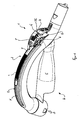
- the handle H is a hose handle for one not shown Canister vacuum cleaner and accordingly between an approach for one Suction hose S and a coupling piece R for a pipe and / or attachments arranged.
- the hose handle is hollow or tubular as a plastic injection molded part educated. In a manner known per se, the hose handle H is around a container C expanded to accommodate an upholstery brush, etc.
- the device 1 comprises a slider 2, which is connected to a guide rail 3 Slidably held sliding element 4 is actuated.
- a flexible Connecting element 5 becomes a mechanically coupled driver 6 within a Housing G for actuating an actuating element 8 in the form of a potentiometer emotional.
- This structure makes it more coordinated using one another Plastics created a durable device 1 which in the direction of a longitudinal axis M of the handle H over an entire length and in each handle position of one hand is operable.
- a particularly to secure a set position of the Slider 2 against accidental slipping is desired low friction adjustable between the moving parts.
- a partial one Design of the surface with a haptically pleasant and non-slip Knob structure N supports the comfort aspect. So in a very convenient way An engine power is set via the slider 2.
- a button T is included provided to move from any position of the slider 2 immediately into a To enter standby mode with the engine switched off, a so-called Standby mode.
- FIG. 2 shows another view of the embodiment of the handle H of Figure 1 in an enlarged detail.
- the sliding element 4, the connecting element 5 and the driver 6th are made in one piece as a plastic part. So that manufacturing and Assembly considerably simplified.
- the compact design of the in the Housing G illustrates elements used, with an area around a flap K can now be seen particularly well.
- a battery for power supply the not further visible transmitter unit SE used. It's a lithium cell, which is dimensioned for approx. 100,000 switching commands.
- the number of switching commands will advantageously by means of evaluation electronics as part of the transmitter unit SE even more energy-saving that further processing and transmission of Do not command with a slight change in engine power in a unit of time be transmitted.
- a radio transmission link F between a combination of one Transmitter unit SE and a receiver unit E are provided.
- the combination of Transmitter unit SE and receiver unit E is for data transmission over a distance of several meters, especially over a distance of up to approx. 3 to 5m.
- the transmitter unit SE is for outputting 64 coded signals in a relatively high Frequency range designed for humans also by the radiation power is harmless and is not currently used by other devices. Height Frequencies have the advantage that they can pass through obstacles and still not have a very long range.
- Radio transmission link F created the interference of other devices by the choice the frequency range of the transmitter unit SE and the receiver unit E largely excludes, because overreaches of such signals are extremely unlikely. Malfunctions of similar devices are excluded by the choice of coding.
- a Setting the receiver unit E to a transmitter unit SE is advantageous made automatically. It is pre-programmed in the receiver unit E, see above that during and initial commissioning and inserting a battery into the Transmitter unit SE on the handle H after receiving 10 transmission signals a respective coding is automatically recognized and for further operation in the Receiver unit E is stored for decoding.
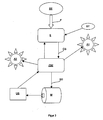
- FIG 3 shows a sketch of a signal run in a vacuum cleaner using an overall device according to the invention with a transmitter unit SE and one via a monodirectional radio connection or Radio link F connected receiver unit E.
- a transmitter unit SE For setting the receiver unit E on a new transmitter unit SE with establishment of the correct code is a hidden one Service button ST provided.
- a warning display A1 in the form of a flashing LED on the vacuum cleaner housing switched on. This warning display A1 opens a malfunction, which is usually caused, for example, by replacing the battery can be fixed in the handle H.
- the decoded control signals CS are received by the receiving unit E.
- a central control unit ZSE for evaluation and implementation in the respective Control variables SG sent in particular for controlling a motor M etc.
- the vacuum sensor US monitors the Suction power of the motor M and as a threshold switch determines whether and when to high negative pressure is reached. In this case, there is most likely a malfunction Form of a blockage in a suction power etc. before or a suction filter is overfilled.
- the central switch is triggered by a return signal from the vacuum sensor US Control unit ZSE in turn a warning indicator, namely now a light emitting diode A2.
- the radio link F between the transmitter unit SE and the associated receiver unit E bidirectionally educated.
- the transmitter unit SE and the receiver unit E are then each as Sending and receiving units trained.
- This is advantageously the Possibility of returning acknowledgment signals or error messages from the Vacuum cleaner body to handle H.
- such signals can be optical, tactile or processed acoustically for a user and output to a Ensure knowledge.
Landscapes
- Engineering & Computer Science (AREA)
- Mechanical Engineering (AREA)
- Electric Vacuum Cleaner (AREA)
- Central Heating Systems (AREA)
- Control Of Electric Motors In General (AREA)
- Selective Calling Equipment (AREA)
Abstract
Description
- Figur 1:
- eine Schnittdarstellung einer dreidimensionale Ansicht eines Handgriffs für einen Staubsauger in einer ersten Ausführungsform mit einer darin integrierten Ausführungsform einer erfindungsgemäßen Vorrichtung;
- Figur 2:
- eine weitere Ansicht der Ausführungsform von Fig. 1 und
- Figur 3:
- eine skizzierte Darstellung eines Signallaufes in einem Staubsauger unter Verwendung einer erfindungsgemäßen Vorrichtung.
Claims (9)
- Vorrichtung zur Steuerung eines elektrischen Gerätes, insbesondere zur Ansteuerung elektrisch oder elektronisch bedienbarer Funktionsteile eines Bodenpflegegerätes oder eines ähnlichen Haushaltgerätes, das derart ausgebildet ist, dass es entweder von einem Benutzer per Hand getragen oder im wesentlichen im Bereich einer Arbeitseinheit geführt wird, wobei die Vorrichtung zur Steuerung an einem Handgriff vorgesehen ist,
dadurch gekennzeichnet,
eine Sendeeinheit (SE) vorgesehen ist, der zur Aussendung eines Steuerungssignals in Form elektromagnetischer Wellen einer solchen Frequenz und Strahlungsleistung ausgebildet ist, dass das Steuerungssignal von einer korrespondierenden Empfängereinheit (E) in einem Nahbereich empfangen wird. - Vorrichtung nach Anspruch 1, dadurch gekennzeichnet, dass die Vorrichtung (1) zum Senden von Steuerungssignalen durch eine Wand hindurch und/oder vorzugsweise auch zum Empfangen von Steuerungssignalen und/oder Quittungen oder sonstiger Rücksendeinformation ausgebildet ist.
- Vorrichtung nach einem oder beiden der vorhergehenden Ansprüche, dadurch gekennzeichnet, dass die Vorrichtung (1) als Kombination aus Sendeeinheit (S) und Empfängereinheit (E) für eine Datenübertragung über eine Distanz von mehreren Metern, insbesondere über einen Abstand bis zu ca. 3 bis 5m ausgelegt ist.
- Vorrichtung nach einem oder mehreren der vorhergehenden Ansprüche, dadurch gekennzeichnet, dass die Sendeeinheit (S) zum Codieren des Steuersignals ausgebildet ist, wobei vorzugsweise 64 verschiedene Codes vorgesehen sind.
- Vorrichtung nach einem oder mehreren der vorhergehenden Ansprüche, dadurch gekennzeichnet, dass ist der Empfängereinheit (E) zu einer automatischen Abstimmung auf eine Sendeeinheit (S) ausgebildet, wobei die Empfängereinheit (E) insbesondere bei einer ersten Inbetriebnahme und/oder nach einem Batteriewechsel zu einer automatischen Abstimmung auf die ihn mit einem Steuersignal versorgenden Sendeeinheit (S) ausgebildet ist.
- Vorrichtung nach einem oder mehreren der vorhergehenden Ansprüche, dadurch gekennzeichnet, dass die Sendeeinheit (S) als Elektronikbaustein vorzugsweise in hochintegrierter Form ausgebildet und in dem Schlauch-Handgriff (H) integriert ist.
- Vorrichtung nach einem oder mehreren der vorhergehenden Ansprüche, dadurch gekennzeichnet, dass die Sendeeinheit (S) mit einem elektrischen Ausgang eines länglich ausgebildeten Schiebereglers (2), eines langgestreckt ausgeführten Sensors und/oder eines sonstigen Schaltelementes an dem Handgriff (H) des Haushaltgerätes verbunden ist, wobei das Schaltelement derart ausgebildet und an dem Handgriff (H) angeordnet ist, dass eine Einstellung durch eine Hand und/oder einen Finger eines Anwenders ermöglicht ist.
- Vorrichtung nach einem oder mehreren der vorhergehenden Ansprüche, dadurch gekennzeichnet, dass an dem Handgriff (H) ein Taster (T) zum direkten Einschalten eines Bereitschaftsbetriebszustandes bzw. Stand-by Modes vorgesehen ist.
- Vorrichtung nach einem oder mehreren der vorhergehenden Ansprüche, dadurch gekennzeichnet, dass an dem Handgriff (H) ein von Hand aufklappbarer Deckel zum Einsetzen einer Batterie in ein geschlossenes Batteriefach vorgesehen ist.
Applications Claiming Priority (2)
| Application Number | Priority Date | Filing Date | Title |
|---|---|---|---|
| DE10148512 | 2001-10-01 | ||
| DE10148512A DE10148512A1 (de) | 2001-10-01 | 2001-10-01 | Vorrichtung zur Steuerung eines elektrischen Gerätes |
Publications (3)
| Publication Number | Publication Date |
|---|---|
| EP1297777A2 true EP1297777A2 (de) | 2003-04-02 |
| EP1297777A3 EP1297777A3 (de) | 2006-04-26 |
| EP1297777B1 EP1297777B1 (de) | 2008-11-12 |
Family
ID=7701066
Family Applications (1)
| Application Number | Title | Priority Date | Filing Date |
|---|---|---|---|
| EP02021064A Revoked EP1297777B1 (de) | 2001-10-01 | 2002-09-20 | Vorrichtung zur Steuerung eines elektrischen Gerätes |
Country Status (3)
| Country | Link |
|---|---|
| EP (1) | EP1297777B1 (de) |
| AT (1) | ATE413835T1 (de) |
| DE (2) | DE10148512A1 (de) |
Cited By (1)
| Publication number | Priority date | Publication date | Assignee | Title |
|---|---|---|---|---|
| WO2018224627A1 (de) | 2017-06-08 | 2018-12-13 | Festool Gmbh | Staubsauger |
Families Citing this family (1)
| Publication number | Priority date | Publication date | Assignee | Title |
|---|---|---|---|---|
| DE102007016042B4 (de) * | 2006-03-30 | 2014-06-12 | Klaus Kunzmann | Wohnzwecken dienendes Fahrzeug mit Staubsauger |
Family Cites Families (5)
| Publication number | Priority date | Publication date | Assignee | Title |
|---|---|---|---|---|
| DE2923588A1 (de) * | 1979-06-11 | 1980-12-18 | Miele & Cie | Staubsauger, insbesondere bodenstaubsauger |
| DE19736595B4 (de) * | 1997-08-22 | 2007-04-12 | BSH Bosch und Siemens Hausgeräte GmbH | Drahtlose Fernbetätigungseinrichtung für einen Staubsauger |
| DE19902130A1 (de) * | 1998-01-23 | 1999-09-23 | Kwang Ju Electronics Co Ltd | Fernsteuervorrichtung eines Staubsaugers |
| DE19938680C2 (de) * | 1999-08-14 | 2003-09-25 | Wessel Werk Gmbh | Bodendüse für Staubsauggeräte |
| IT1315384B1 (it) * | 2000-02-01 | 2003-02-10 | T P A Impex Spa | Dispositivo di comando, particolarmente per apparecchi di puliziadomestica e/o industriale. |
-
2001
- 2001-10-01 DE DE10148512A patent/DE10148512A1/de not_active Withdrawn
-
2002
- 2002-09-20 DE DE50213001T patent/DE50213001D1/de not_active Expired - Lifetime
- 2002-09-20 AT AT02021064T patent/ATE413835T1/de not_active IP Right Cessation
- 2002-09-20 EP EP02021064A patent/EP1297777B1/de not_active Revoked
Cited By (5)
| Publication number | Priority date | Publication date | Assignee | Title |
|---|---|---|---|---|
| WO2018224627A1 (de) | 2017-06-08 | 2018-12-13 | Festool Gmbh | Staubsauger |
| EP3634192B1 (de) * | 2017-06-08 | 2022-04-06 | Festool GmbH | Staubsauger |
| US11647880B2 (en) | 2017-06-08 | 2023-05-16 | Festool Gmbh | Vacuum cleaner |
| EP3854282B1 (de) * | 2017-06-08 | 2024-01-10 | Festool GmbH | Staubsauger |
| EP4306023A3 (de) * | 2017-06-08 | 2024-05-15 | Festool GmbH | Staubsauger |
Also Published As
| Publication number | Publication date |
|---|---|
| DE10148512A1 (de) | 2003-04-24 |
| EP1297777A3 (de) | 2006-04-26 |
| EP1297777B1 (de) | 2008-11-12 |
| DE50213001D1 (de) | 2008-12-24 |
| ATE413835T1 (de) | 2008-11-15 |
Similar Documents
| Publication | Publication Date | Title |
|---|---|---|
| EP3212335B1 (de) | Spritzpistole für hochdruckreinigungsgerät | |
| EP2628427B1 (de) | Sauggerät mit einem Sauggerät-Sender und Extern-Kommunikationseinrichtung dafür | |
| DE60210043T2 (de) | Schutzvorrichtung für elektrische haushaltsgeräte | |
| EP0891745B1 (de) | Elektrisch betriebene medizinische Vorrichtung | |
| EP3595934B1 (de) | Drehsteller für ein fahrzeug | |
| EP3376907B1 (de) | Elektromotorischer möbelantrieb, möbel und verfahren zum steuern eines elektromotorischen möbelantriebs | |
| EP0948251A1 (de) | Sicherheitsschaltvorrichtung für ein elektromotorisch angetriebenes gartengerät | |
| WO2006061133A1 (de) | Reinigungsroboter | |
| DE102016101126A1 (de) | System und Verfahren zur Beschränkung der Bewegung eines Roboters | |
| DE102009024990B4 (de) | Elektrogerät mit einer Halterung für eine Fernbedienung | |
| EP1297777A2 (de) | Vorrichtung zur Steuerung eines elektrischen Gerätes | |
| EP3454706B1 (de) | Bedieneinrichtung und rückentragbares reinigungsgerät | |
| EP1374199B1 (de) | Fernsteuerungseinrichtung für selbstfahrende arbeitsgeräte | |
| EP2602679A1 (de) | Bedienelement für ein Haushaltsgerät, Bedieneinheit eines Haushaltsgeräts zur Aufnahme eines solchen Bedienelements und Haushaltsgerät mit einer solchen Bedieneinheit und einem solchen Bedienelement | |
| EP4081012A1 (de) | Elektrogerät mit zumindest einem handgriff zur sicheren führung des elektrogeräts und verfahren zum betreiben des elektrogeräts | |
| DE102005063321B4 (de) | Steuereinrichtung mit Handbedienung für Verstellantriebe | |
| DE102017115436A1 (de) | Verfahren zur Benutzersteuerung eines Mehrzweckstaubsaugers | |
| EP0818595B1 (de) | Hausterminal für einen Garagentorantrieb | |
| DE102017100541A1 (de) | Mehrzweckstaubsauger | |
| DE69009696T2 (de) | Staubsauger. | |
| EP1472708B1 (de) | Elektrische schaltanordnung für ein elektrowerkzeug | |
| DE10148513B4 (de) | Vorrichtung zur Steuerung eines elektrischen Gerätes | |
| EP1068386B1 (de) | Vorrichtung zur drahtlosen steuerung einer nähmaschine | |
| LU103410B1 (de) | Mobiler Dunstabzug, Induktionsvorrichtung und Verfahren zum Betreiben eines mobilen Dunstabzugs | |
| DE102007036220A1 (de) | Vorrichtung zur Abstrahlung von Lichtsignalen sowie eine solche Vorrichtung enthaltende Basisstation eines diese und zumindest einen Staubsammelroboter umfassenden Staubsammelrobotersystems |
Legal Events
| Date | Code | Title | Description |
|---|---|---|---|
| PUAI | Public reference made under article 153(3) epc to a published international application that has entered the european phase |
Free format text: ORIGINAL CODE: 0009012 |
|
| AK | Designated contracting states |
Kind code of ref document: A2 Designated state(s): AT BE BG CH CY CZ DE DK EE ES FI FR GB GR IE IT LI LU MC NL PT SE SK TR |
|
| AX | Request for extension of the european patent |
Extension state: AL LT LV MK RO SI |
|
| RAP1 | Party data changed (applicant data changed or rights of an application transferred) |
Owner name: BSH BOSCH UND SIEMENS HAUSGERAETE GMBH |
|
| PUAL | Search report despatched |
Free format text: ORIGINAL CODE: 0009013 |
|
| AK | Designated contracting states |
Kind code of ref document: A3 Designated state(s): AT BE BG CH CY CZ DE DK EE ES FI FR GB GR IE IT LI LU MC NL PT SE SK TR |
|
| AX | Request for extension of the european patent |
Extension state: AL LT LV MK RO SI |
|
| 17P | Request for examination filed |
Effective date: 20061026 |
|
| AKX | Designation fees paid |
Designated state(s): AT BE BG CH CY CZ DE DK EE ES FI FR GB GR IE IT LI LU MC NL PT SE SK TR |
|
| 17Q | First examination report despatched |
Effective date: 20061222 |
|
| GRAP | Despatch of communication of intention to grant a patent |
Free format text: ORIGINAL CODE: EPIDOSNIGR1 |
|
| GRAS | Grant fee paid |
Free format text: ORIGINAL CODE: EPIDOSNIGR3 |
|
| GRAA | (expected) grant |
Free format text: ORIGINAL CODE: 0009210 |
|
| AK | Designated contracting states |
Kind code of ref document: B1 Designated state(s): AT BE BG CH CY CZ DE DK EE ES FI FR GB GR IE IT LI LU MC NL PT SE SK TR |
|
| REG | Reference to a national code |
Ref country code: GB Ref legal event code: FG4D Free format text: NOT ENGLISH |
|
| REG | Reference to a national code |
Ref country code: CH Ref legal event code: EP |
|
| REG | Reference to a national code |
Ref country code: IE Ref legal event code: FG4D Free format text: LANGUAGE OF EP DOCUMENT: GERMAN |
|
| REF | Corresponds to: |
Ref document number: 50213001 Country of ref document: DE Date of ref document: 20081224 Kind code of ref document: P |
|
| PG25 | Lapsed in a contracting state [announced via postgrant information from national office to epo] |
Ref country code: ES Free format text: LAPSE BECAUSE OF FAILURE TO SUBMIT A TRANSLATION OF THE DESCRIPTION OR TO PAY THE FEE WITHIN THE PRESCRIBED TIME-LIMIT Effective date: 20090223 |
|
| NLV1 | Nl: lapsed or annulled due to failure to fulfill the requirements of art. 29p and 29m of the patents act | ||
| PG25 | Lapsed in a contracting state [announced via postgrant information from national office to epo] |
Ref country code: FI Free format text: LAPSE BECAUSE OF FAILURE TO SUBMIT A TRANSLATION OF THE DESCRIPTION OR TO PAY THE FEE WITHIN THE PRESCRIBED TIME-LIMIT Effective date: 20081112 Ref country code: NL Free format text: LAPSE BECAUSE OF FAILURE TO SUBMIT A TRANSLATION OF THE DESCRIPTION OR TO PAY THE FEE WITHIN THE PRESCRIBED TIME-LIMIT Effective date: 20081112 |
|
| REG | Reference to a national code |
Ref country code: IE Ref legal event code: FD4D |
|
| PG25 | Lapsed in a contracting state [announced via postgrant information from national office to epo] |
Ref country code: BG Free format text: LAPSE BECAUSE OF FAILURE TO SUBMIT A TRANSLATION OF THE DESCRIPTION OR TO PAY THE FEE WITHIN THE PRESCRIBED TIME-LIMIT Effective date: 20090212 Ref country code: IE Free format text: LAPSE BECAUSE OF FAILURE TO SUBMIT A TRANSLATION OF THE DESCRIPTION OR TO PAY THE FEE WITHIN THE PRESCRIBED TIME-LIMIT Effective date: 20081112 Ref country code: DK Free format text: LAPSE BECAUSE OF FAILURE TO SUBMIT A TRANSLATION OF THE DESCRIPTION OR TO PAY THE FEE WITHIN THE PRESCRIBED TIME-LIMIT Effective date: 20081112 Ref country code: EE Free format text: LAPSE BECAUSE OF FAILURE TO SUBMIT A TRANSLATION OF THE DESCRIPTION OR TO PAY THE FEE WITHIN THE PRESCRIBED TIME-LIMIT Effective date: 20081112 |
|
| PLBI | Opposition filed |
Free format text: ORIGINAL CODE: 0009260 |
|
| PG25 | Lapsed in a contracting state [announced via postgrant information from national office to epo] |
Ref country code: SE Free format text: LAPSE BECAUSE OF FAILURE TO SUBMIT A TRANSLATION OF THE DESCRIPTION OR TO PAY THE FEE WITHIN THE PRESCRIBED TIME-LIMIT Effective date: 20090212 Ref country code: PT Free format text: LAPSE BECAUSE OF FAILURE TO SUBMIT A TRANSLATION OF THE DESCRIPTION OR TO PAY THE FEE WITHIN THE PRESCRIBED TIME-LIMIT Effective date: 20090413 Ref country code: CZ Free format text: LAPSE BECAUSE OF FAILURE TO SUBMIT A TRANSLATION OF THE DESCRIPTION OR TO PAY THE FEE WITHIN THE PRESCRIBED TIME-LIMIT Effective date: 20081112 |
|
| PLAX | Notice of opposition and request to file observation + time limit sent |
Free format text: ORIGINAL CODE: EPIDOSNOBS2 |
|
| 26 | Opposition filed |
Opponent name: AKTIEBOLAGET ELECTROLUX Effective date: 20090811 |
|
| PG25 | Lapsed in a contracting state [announced via postgrant information from national office to epo] |
Ref country code: SK Free format text: LAPSE BECAUSE OF FAILURE TO SUBMIT A TRANSLATION OF THE DESCRIPTION OR TO PAY THE FEE WITHIN THE PRESCRIBED TIME-LIMIT Effective date: 20081112 |
|
| PLAF | Information modified related to communication of a notice of opposition and request to file observations + time limit |
Free format text: ORIGINAL CODE: EPIDOSCOBS2 |
|
| PLBB | Reply of patent proprietor to notice(s) of opposition received |
Free format text: ORIGINAL CODE: EPIDOSNOBS3 |
|
| BERE | Be: lapsed |
Owner name: BSH BOSCH UND SIEMENS HAUSGERATE G.M.B.H. Effective date: 20090930 |
|
| PG25 | Lapsed in a contracting state [announced via postgrant information from national office to epo] |
Ref country code: MC Free format text: LAPSE BECAUSE OF NON-PAYMENT OF DUE FEES Effective date: 20090930 |
|
| REG | Reference to a national code |
Ref country code: CH Ref legal event code: PL |
|
| GBPC | Gb: european patent ceased through non-payment of renewal fee |
Effective date: 20090920 |
|
| REG | Reference to a national code |
Ref country code: FR Ref legal event code: ST Effective date: 20100531 |
|
| PG25 | Lapsed in a contracting state [announced via postgrant information from national office to epo] |
Ref country code: FR Free format text: LAPSE BECAUSE OF NON-PAYMENT OF DUE FEES Effective date: 20090930 |
|
| PG25 | Lapsed in a contracting state [announced via postgrant information from national office to epo] |
Ref country code: BE Free format text: LAPSE BECAUSE OF NON-PAYMENT OF DUE FEES Effective date: 20090930 |
|
| PG25 | Lapsed in a contracting state [announced via postgrant information from national office to epo] |
Ref country code: LI Free format text: LAPSE BECAUSE OF NON-PAYMENT OF DUE FEES Effective date: 20090930 Ref country code: GR Free format text: LAPSE BECAUSE OF FAILURE TO SUBMIT A TRANSLATION OF THE DESCRIPTION OR TO PAY THE FEE WITHIN THE PRESCRIBED TIME-LIMIT Effective date: 20090213 Ref country code: CH Free format text: LAPSE BECAUSE OF NON-PAYMENT OF DUE FEES Effective date: 20090930 |
|
| PG25 | Lapsed in a contracting state [announced via postgrant information from national office to epo] |
Ref country code: GB Free format text: LAPSE BECAUSE OF NON-PAYMENT OF DUE FEES Effective date: 20090920 Ref country code: AT Free format text: LAPSE BECAUSE OF NON-PAYMENT OF DUE FEES Effective date: 20090920 |
|
| PG25 | Lapsed in a contracting state [announced via postgrant information from national office to epo] |
Ref country code: IT Free format text: LAPSE BECAUSE OF FAILURE TO SUBMIT A TRANSLATION OF THE DESCRIPTION OR TO PAY THE FEE WITHIN THE PRESCRIBED TIME-LIMIT Effective date: 20081112 |
|
| PG25 | Lapsed in a contracting state [announced via postgrant information from national office to epo] |
Ref country code: LU Free format text: LAPSE BECAUSE OF NON-PAYMENT OF DUE FEES Effective date: 20090920 |
|
| PG25 | Lapsed in a contracting state [announced via postgrant information from national office to epo] |
Ref country code: TR Free format text: LAPSE BECAUSE OF FAILURE TO SUBMIT A TRANSLATION OF THE DESCRIPTION OR TO PAY THE FEE WITHIN THE PRESCRIBED TIME-LIMIT Effective date: 20081112 |
|
| PG25 | Lapsed in a contracting state [announced via postgrant information from national office to epo] |
Ref country code: CY Free format text: LAPSE BECAUSE OF FAILURE TO SUBMIT A TRANSLATION OF THE DESCRIPTION OR TO PAY THE FEE WITHIN THE PRESCRIBED TIME-LIMIT Effective date: 20081112 |
|
| RDAF | Communication despatched that patent is revoked |
Free format text: ORIGINAL CODE: EPIDOSNREV1 |
|
| APBM | Appeal reference recorded |
Free format text: ORIGINAL CODE: EPIDOSNREFNO |
|
| APBP | Date of receipt of notice of appeal recorded |
Free format text: ORIGINAL CODE: EPIDOSNNOA2O |
|
| APAH | Appeal reference modified |
Free format text: ORIGINAL CODE: EPIDOSCREFNO |
|
| APBQ | Date of receipt of statement of grounds of appeal recorded |
Free format text: ORIGINAL CODE: EPIDOSNNOA3O |
|
| PGFP | Annual fee paid to national office [announced via postgrant information from national office to epo] |
Ref country code: DE Payment date: 20140930 Year of fee payment: 13 |
|
| RAP2 | Party data changed (patent owner data changed or rights of a patent transferred) |
Owner name: BSH HAUSGERAETE GMBH |
|
| REG | Reference to a national code |
Ref country code: DE Ref legal event code: R081 Ref document number: 50213001 Country of ref document: DE Owner name: BSH HAUSGERAETE GMBH, DE Free format text: FORMER OWNER: BSH BOSCH UND SIEMENS HAUSGERAETE GMBH, 81739 MUENCHEN, DE Effective date: 20150407 |
|
| REG | Reference to a national code |
Ref country code: DE Ref legal event code: R064 Ref document number: 50213001 Country of ref document: DE Ref country code: DE Ref legal event code: R103 Ref document number: 50213001 Country of ref document: DE |
|
| APBU | Appeal procedure closed |
Free format text: ORIGINAL CODE: EPIDOSNNOA9O |
|
| RDAG | Patent revoked |
Free format text: ORIGINAL CODE: 0009271 |
|
| STAA | Information on the status of an ep patent application or granted ep patent |
Free format text: STATUS: PATENT REVOKED |
|
| 27W | Patent revoked |
Effective date: 20150520 |
|
| REG | Reference to a national code |
Ref country code: DE Ref legal event code: R107 Ref document number: 50213001 Country of ref document: DE |
|
| REG | Reference to a national code |
Ref country code: AT Ref legal event code: MA03 Ref document number: 413835 Country of ref document: AT Kind code of ref document: T Effective date: 20150520 |