EP1297323B1 - Verfahren zur optischen detektion einer beleuchteten probe in mehreren detektionskanälen - Google Patents
Verfahren zur optischen detektion einer beleuchteten probe in mehreren detektionskanälen Download PDFInfo
- Publication number
- EP1297323B1 EP1297323B1 EP01965025A EP01965025A EP1297323B1 EP 1297323 B1 EP1297323 B1 EP 1297323B1 EP 01965025 A EP01965025 A EP 01965025A EP 01965025 A EP01965025 A EP 01965025A EP 1297323 B1 EP1297323 B1 EP 1297323B1
- Authority
- EP
- European Patent Office
- Prior art keywords
- detection
- channel
- channels
- sample
- limit value
- Prior art date
- Legal status (The legal status is an assumption and is not a legal conclusion. Google has not performed a legal analysis and makes no representation as to the accuracy of the status listed.)
- Revoked
Links
- 238000001514 detection method Methods 0.000 title claims abstract description 17
- 238000000034 method Methods 0.000 title claims abstract description 11
- 238000005286 illumination Methods 0.000 claims abstract description 5
- 230000003595 spectral effect Effects 0.000 claims description 5
- 230000003321 amplification Effects 0.000 claims description 2
- 238000003199 nucleic acid amplification method Methods 0.000 claims description 2
- 230000003287 optical effect Effects 0.000 claims 1
- 239000000523 sample Substances 0.000 description 7
- 230000001419 dependent effect Effects 0.000 description 2
- 238000011156 evaluation Methods 0.000 description 1
- 230000005284 excitation Effects 0.000 description 1
- 238000005259 measurement Methods 0.000 description 1
Images
Classifications
-
- G—PHYSICS
- G02—OPTICS
- G02B—OPTICAL ELEMENTS, SYSTEMS OR APPARATUS
- G02B21/00—Microscopes
- G02B21/18—Arrangements with more than one light path, e.g. for comparing two specimens
-
- G—PHYSICS
- G02—OPTICS
- G02B—OPTICAL ELEMENTS, SYSTEMS OR APPARATUS
- G02B21/00—Microscopes
- G02B21/0004—Microscopes specially adapted for specific applications
- G02B21/002—Scanning microscopes
Definitions
- Laser scanning microscopes use lasers of different wavelengths to illuminate and excite the samples.
- the light from the sample also has different wavelengths, depending on the illumination and on the sample itself. (Fluorescence).
- the light returning from the sample is measured and evaluated in the form of image representations.
- DE19829944A1 describes a method for configuring a laser scanning microscope.
- data records are stored on a computer and computationally linked to find an optimal configuration for excitation and an optimal configuration for detecting the dye to be examined.
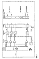
- V n comparators K or triggers are used after the amplification, which are adjustable in their switching threshold by a digital-to-analog converter.
- the threshold is set to be above the noise level.
- the output of the comparators is respectively fed to a register R, which has a common clear input C and which can be read by a computer. Before a measurement, the register (n-bit wide) is reset. If a scan pass is now initiated, those comparators will switch which receive a signal on their input which is above the set threshold. Channels which are arranged, for example, wavelength-dependent and do not send a signal which is above the switching threshold of the comparator are uninteresting for the evaluation and can be ignored or regarded as a sum signal. If the comparator is executed as a window comparator and both switching thresholds (upper and lower) are adjustable (eg via digital-analog converter) then Signals can be separated and evaluated, which are either only within the thresholds or outside (below or above the thresholds).
- the register immediately provides information about the spectral components of the detected light.
- Figure 1 shows the principle of the circuit.
Landscapes
- Physics & Mathematics (AREA)
- Chemical & Material Sciences (AREA)
- Analytical Chemistry (AREA)
- General Physics & Mathematics (AREA)
- Optics & Photonics (AREA)
- Microscoopes, Condenser (AREA)
- Investigating, Analyzing Materials By Fluorescence Or Luminescence (AREA)
- Investigating Or Analysing Materials By Optical Means (AREA)
- Spectrometry And Color Measurement (AREA)
- Photometry And Measurement Of Optical Pulse Characteristics (AREA)
Description
- Bei Laser-Scanning-Mikroskopen werden zur Beleuchtung und Anregung der Proben Laser unterschiedlicher Wellenlängen eingesetzt. Das Licht von der Probe weist ebenfalls unterschiedliche Wellenlängen auf, abhängig von der Beleuchtung und von der Probe selbst. (Fluoreszenz). Das von der Probe zurückkommende Licht wird gemessen und ausgewertet in Form von Bilddarstellungen .
- Bei einem n-kanaligen System müssen alle Kanäle ausgewertet werden um festzustellen, auf welchen der Kanäle wirklich Daten zu erfassen sind.
- Üblicherweise gibt es bei Mikroskopsystemen 2-4 Aufnahmekanäle, die bildmäßig ausgewertet werden. Um festzustellen in welchen Kanälen Licht detektiert wird, muß n/4 mal die Probe gescannt und damit auch beleuchtet werden.
- Dieser Vorgang ist aufwendig, bedeutet Zeitverlust und unnötige Belastung der Probe durch Laserlicht.
-
DE19829944A1 beschreibt ein Verfahren zur Konfiguration eines Laser-Scanning-Mikroskopes. - Hierzu werden Datensätze auf einem Rechner abgelegt
und rechnerisch miteinander verknüpft, um eine optimale Konfiguration zur Anregung und eine optimale Konfiguration zur Detektion des zu untersuchenden Farbstoffes aufzufinden. - Bei einem n-kanaligen Detektionssystem D werden nach der Verstärkung V n-Komparatoren K bzw. Trigger (für jeden Detektionskanal einen) eingesetzt, die in ihrer Schaltschwelle durch einen Digital-Analog-Wandler einstellbar sind.
- Die Schwelle wird so eingestellt, daß sie oberhalb des Rauschpegels liegt. Der Ausgang der Komparatoren wird jeweils auf ein Register R geführt, welches über einen gemeinsamen Clear-Eingang C verfügt und das von einem Computer gelesen werden kann. Vor einer Messung wird das Register ( n-Bit breit ) zurückgesetzt. Wird nun ein Scann-Durchlauf angestoßen, so werden diejenigen Komparatoren schalten, die ein Signal auf ihren Eingang erhalten das über der eingestellten Schwelle liegt. Kanäle, die z.B. wellenlängenabhängig angeordnet sind und kein Signal senden, das über der Schaltschwelle des Komparators liegt sind für die Auswertung uninteressant und können vernachlässigt oder als Summensignal betrachtet werden. Wird der Komparator als Fensterkomparator ausgeführt und beide Schaltschwellen ( obere und untere) sind einstellbar ( z.B. über Digital-AnalogWandler) dann können Signale separiert und ausgewertet werden, die entweder nur innerhalb der Schwellen oder außerhalb ( unter bzw. über den Schwellen ) liegen.
- Schon nach einem Scann kann in dem n-Bit breitem Register abgelesen werden, in welchem der n-Kanäle Daten zu erwarten sind.
- Sind die Detektoren noch spektral angeordnet ( Art und Weise ist dabei beliebig) so gibt das Register sofort eine Information über die spektralen Anteile des detektierten Lichtes.
- Diese Information ist ein wichtiger Bestandteil für die richtige Einstellung eines n-kanaligen Systems. Aus dieser Information können alle Kanäle auf die jeweiligen Wellenlängen eingerichtet werden ohne subjektive Fehler zu machen. Es besteht die Möglichkeit der Autokonfiguration ( online ) eines Systems in Bezug auf spektrale Aufnahmen. Weiterhin gibt es Hinweise für eine manuelle optimale Auswahl ( off line)
- Im Bild 1 wird das Prinzip der Schaltung dargestellt.
- Vorteile des erfindungsgemäßen Verfahrens sind:
- bei einem n-kanaligen Detektionssystem stehen sofort Informationen über die aktiven Kanäle bereit
- sind die n-Detektionskanäle spektral empfindlich angeordnet so kann sofort eine Information über die spektralen Anteile angezeigt werden
- sind mehr Detektionskanäle als Aufnahmekanäle vorhanden, so entfällt das mehrmalige Scannen um festzustellen wo Daten vorhanden sind, d.h. geringere Belastung der Probe
- durch Kenntnis der aktiven Kanäle kann das System automatisch die Konfiguration einstellen (aktive Kanäle und Wellenlängenabhängige Einstellungen von Filterkombinationen).
- Das System zeigt an in welchen Kanälen Daten zu erwarten sind und mit welcher Wellenlänge; diese Information erspart dem Operator zeitaufwendige Probeaufnahmen bei manueller Einstellung des Systems.
Claims (6)
- Verfahren zur optischen Detektion einer beleuchteten Probe in einem Mikroskopsystem mit mehreren Aufnahmekanälen zur Lichtdetektion,
wobei für mindestens einen Kanal ein oberer und/ oder unterer Grenzwert eingestellt wird und beim Erreichen dieses Grenzwertes jeder der eingestellten Detektionskänale bezüglich seiner Betriebsweise verändert wird, indem der Detektionskanal abgeschaltt wird oder seine Verstärkung geändert wird oder eine Rückkopplung zur Lichtquelle zur Änderung der Beleuchtungsparameter erfolgt oder die Signale des Detektionskanals bei der Weiterverarbeitung unberücksichtig bleiben. - Verfahren nach Anspruch 1,
wobei eine punktweise Beleuchtung und Detektion erfolgt. - Verfahren nach Anspruch 1,
wobei eine parallele Beleuchtung und Detektion erfolgt. - Verfahren nach Anspruch 3,
wobei eine Mikrotiterplatte beleuchtet und detektiert wird. - Verfahren nach einem der Ansprüche 1-4,
wobei eine spektrale Aufspaltung des von der Probe emittierten Lichtes erfolgt. - Verfahren nach Anspruch 5,
wobei zur spektralen Aufspaltung ein dispergierendes Element vorgesehen ist, dem ein Multikanaldetektor nachgeordnet ist.
Applications Claiming Priority (3)
| Application Number | Priority Date | Filing Date | Title |
|---|---|---|---|
| DE10033179 | 2000-06-29 | ||
| DE10033179.3A DE10033179B4 (de) | 2000-06-29 | 2000-06-29 | Verfahren zur optischen Detektion einer beleuchteten Probe in mehreren Detektionskanälen |
| PCT/EP2001/007103 WO2002001201A1 (de) | 2000-06-29 | 2001-06-22 | Verfahren zur optischen detektion einer beleuchteten probe in mehreren detektionskanälen |
Publications (2)
| Publication Number | Publication Date |
|---|---|
| EP1297323A1 EP1297323A1 (de) | 2003-04-02 |
| EP1297323B1 true EP1297323B1 (de) | 2008-03-12 |
Family
ID=7648206
Family Applications (1)
| Application Number | Title | Priority Date | Filing Date |
|---|---|---|---|
| EP01965025A Revoked EP1297323B1 (de) | 2000-06-29 | 2001-06-22 | Verfahren zur optischen detektion einer beleuchteten probe in mehreren detektionskanälen |
Country Status (5)
| Country | Link |
|---|---|
| EP (1) | EP1297323B1 (de) |
| JP (2) | JP2004502191A (de) |
| AT (1) | ATE389172T1 (de) |
| DE (2) | DE10033179B4 (de) |
| WO (1) | WO2002001201A1 (de) |
Families Citing this family (3)
| Publication number | Priority date | Publication date | Assignee | Title |
|---|---|---|---|---|
| JP4774745B2 (ja) * | 2005-01-20 | 2011-09-14 | 株式会社ニコン | 顕微鏡システム |
| DE102006030530A1 (de) * | 2006-07-01 | 2008-01-03 | Carl Zeiss Microimaging Gmbh | Verfahren und Anordnung zur Detektierung von Lichtsignalen |
| DE102009043746A1 (de) * | 2009-09-30 | 2011-03-31 | Carl Zeiss Microimaging Gmbh | Verfahren zum Erzeugen von Bildern mit erweitertem Dynamikumfang und optisches Gerät zur Durchführung eines solchen Verfahrens, insbesondere Laser-Scanning-Mikroskop |
Family Cites Families (5)
| Publication number | Priority date | Publication date | Assignee | Title |
|---|---|---|---|---|
| US4376583A (en) * | 1981-05-12 | 1983-03-15 | Aeronca Electronics, Inc. | Surface inspection scanning system |
| SE455646B (sv) * | 1984-10-22 | 1988-07-25 | Radians Innova Ab | Fluorescensanordning |
| GB2318411B (en) * | 1996-10-15 | 1999-03-10 | Simage Oy | Imaging device for imaging radiation |
| DE19829944C2 (de) * | 1998-07-04 | 2002-03-28 | Zeiss Carl Jena Gmbh | Verfahren und Anordnung zur Gerätekonfiguration eines Fluoreszenz-Laserscanmikroskops |
| DE19829981C2 (de) * | 1998-07-04 | 2002-10-17 | Zeiss Carl Jena Gmbh | Verfahren und Anordnung zur konfokalen Mikroskopie |
-
2000
- 2000-06-29 DE DE10033179.3A patent/DE10033179B4/de not_active Expired - Fee Related
-
2001
- 2001-06-22 AT AT01965025T patent/ATE389172T1/de not_active IP Right Cessation
- 2001-06-22 DE DE50113728T patent/DE50113728D1/de not_active Expired - Lifetime
- 2001-06-22 EP EP01965025A patent/EP1297323B1/de not_active Revoked
- 2001-06-22 WO PCT/EP2001/007103 patent/WO2002001201A1/de not_active Ceased
- 2001-06-22 JP JP2002506087A patent/JP2004502191A/ja active Pending
-
2006
- 2006-02-09 JP JP2006032477A patent/JP2006189455A/ja active Pending
Also Published As
| Publication number | Publication date |
|---|---|
| DE10033179B4 (de) | 2016-06-02 |
| ATE389172T1 (de) | 2008-03-15 |
| JP2004502191A (ja) | 2004-01-22 |
| WO2002001201A1 (de) | 2002-01-03 |
| DE10033179A1 (de) | 2002-01-10 |
| WO2002001201A8 (de) | 2004-02-26 |
| DE50113728D1 (de) | 2008-04-24 |
| JP2006189455A (ja) | 2006-07-20 |
| EP1297323A1 (de) | 2003-04-02 |
Similar Documents
| Publication | Publication Date | Title |
|---|---|---|
| DE69030703T2 (de) | Verfahren und Gerät zur Messung von optischen Eigenschaften biologischer Proben | |
| DE2137332C3 (de) | Kolorimeter zur Bestimmung einer Anzahl von Substanzen in einem Fluid | |
| DE69125574T2 (de) | Vorrichtung zur Auswertung fluoreszenzmarkierter Gelelektrophoresemuster | |
| EP3062088B1 (de) | Auswerteschaltung für einen optoelektronischen detektor und verfahren zum aufzeichnen von fluoreszenzereignissen | |
| EP0508257A2 (de) | Spektroskopiekorrelierte Licht-Rastermikroskopie | |
| DE19829944A1 (de) | Verfahren und Anordnung zur Gerätekonfiguration von konfokalen Mikroskopen | |
| DE2922788C2 (de) | Fluoreszenzspektrometer | |
| DE2422016A1 (de) | Diagnose von krankheitszustaenden durch fluoreszenzmessungen unter verwendung von abtastlaserstrahlen | |
| DE2747387A1 (de) | Spektralphotometer | |
| EP1873505B1 (de) | Verfahren und Anordnung zur Detektierung von Lichtsignalen | |
| DE3836280C1 (de) | ||
| DE10033179B4 (de) | Verfahren zur optischen Detektion einer beleuchteten Probe in mehreren Detektionskanälen | |
| DE2450112C3 (de) | Verfahren und Anordnung zur zerstörungsfreien Analyse biologischer Zeilen einer mindestens zwei unterschiedliche, licht bekannter Wellenlänge unterschiedlich stark absorbierende Zellentypen in zueinander festgelegter Lage enthaltenden Probe | |
| DE2614609A1 (de) | Reaktionsmessystem | |
| EP2216671B1 (de) | Vorrichtung und Verfahren zur Detektion mit einem Scanmikroskop | |
| EP0197917A2 (de) | Verfahren zur periodischen Bestimmung einer Messgrösse sowie Einrichtung zur Durchführung dieses Verfahrens | |
| AT502194B1 (de) | Verfahren und vorrichtung zur bestimmung der fluoreszenz einer probe sowie verwendung derselben | |
| DE2742957A1 (de) | Mikroskop | |
| EP4290292A1 (de) | Baukastensystem für eine mikroskopievorrichtung, mikroskopievorrichtung und verfahren zum herstellen einer mikroskopievorrichtung | |
| EP1462793A2 (de) | Lichtabtastvorrichtung | |
| DE10218706B4 (de) | Verfahren zur zeitoptimierten Erfassung von speziellen Spektren mit einem Scanmikroskop | |
| US6747737B2 (en) | Method for optical detection of an illuminated specimen in a plurality of detection channels | |
| EP1139139A2 (de) | Verfahren zur Detektion und Analyse eines Objekts | |
| DE19951188A1 (de) | Verfahren zur Aufzeichnung von Impulssignalen | |
| DE2363188A1 (de) | Verfahren und vorrichtung der mikrospektrographie |
Legal Events
| Date | Code | Title | Description |
|---|---|---|---|
| PUAI | Public reference made under article 153(3) epc to a published international application that has entered the european phase |
Free format text: ORIGINAL CODE: 0009012 |
|
| 17P | Request for examination filed |
Effective date: 20020216 |
|
| AK | Designated contracting states |
Kind code of ref document: A1 Designated state(s): AT BE CH CY DE DK ES FI FR GB GR IE IT LI LU MC NL PT SE TR Designated state(s): AT BE CH CY DE DK ES FI FR GB GR IE IT LI LU MC NL PT SE TR |
|
| AX | Request for extension of the european patent |
Extension state: AL LT LV MK RO SI |
|
| 17Q | First examination report despatched |
Effective date: 20060524 |
|
| GRAP | Despatch of communication of intention to grant a patent |
Free format text: ORIGINAL CODE: EPIDOSNIGR1 |
|
| GRAS | Grant fee paid |
Free format text: ORIGINAL CODE: EPIDOSNIGR3 |
|
| GRAA | (expected) grant |
Free format text: ORIGINAL CODE: 0009210 |
|
| RIN1 | Information on inventor provided before grant (corrected) |
Inventor name: MOEHLER, GUNTER Inventor name: WOLLESCHENSKY, RALF |
|
| RAP1 | Party data changed (applicant data changed or rights of an application transferred) |
Owner name: CARL ZEISS MICROIMAGING GMBH |
|
| AK | Designated contracting states |
Kind code of ref document: B1 Designated state(s): AT BE CH CY DE DK ES FI FR GB GR IE IT LI LU MC NL PT SE TR |
|
| REG | Reference to a national code |
Ref country code: GB Ref legal event code: FG4D Free format text: NOT ENGLISH |
|
| REG | Reference to a national code |
Ref country code: CH Ref legal event code: EP |
|
| REG | Reference to a national code |
Ref country code: IE Ref legal event code: FG4D Free format text: LANGUAGE OF EP DOCUMENT: GERMAN |
|
| GBT | Gb: translation of ep patent filed (gb section 77(6)(a)/1977) |
Effective date: 20080328 |
|
| REF | Corresponds to: |
Ref document number: 50113728 Country of ref document: DE Date of ref document: 20080424 Kind code of ref document: P |
|
| PG25 | Lapsed in a contracting state [announced via postgrant information from national office to epo] |
Ref country code: FI Free format text: LAPSE BECAUSE OF FAILURE TO SUBMIT A TRANSLATION OF THE DESCRIPTION OR TO PAY THE FEE WITHIN THE PRESCRIBED TIME-LIMIT Effective date: 20080312 |
|
| NLV1 | Nl: lapsed or annulled due to failure to fulfill the requirements of art. 29p and 29m of the patents act | ||
| REG | Reference to a national code |
Ref country code: IE Ref legal event code: FD4D |
|
| PG25 | Lapsed in a contracting state [announced via postgrant information from national office to epo] |
Ref country code: SE Free format text: LAPSE BECAUSE OF FAILURE TO SUBMIT A TRANSLATION OF THE DESCRIPTION OR TO PAY THE FEE WITHIN THE PRESCRIBED TIME-LIMIT Effective date: 20080612 Ref country code: PT Free format text: LAPSE BECAUSE OF FAILURE TO SUBMIT A TRANSLATION OF THE DESCRIPTION OR TO PAY THE FEE WITHIN THE PRESCRIBED TIME-LIMIT Effective date: 20080818 Ref country code: ES Free format text: LAPSE BECAUSE OF FAILURE TO SUBMIT A TRANSLATION OF THE DESCRIPTION OR TO PAY THE FEE WITHIN THE PRESCRIBED TIME-LIMIT Effective date: 20080623 |
|
| PG25 | Lapsed in a contracting state [announced via postgrant information from national office to epo] |
Ref country code: NL Free format text: LAPSE BECAUSE OF FAILURE TO SUBMIT A TRANSLATION OF THE DESCRIPTION OR TO PAY THE FEE WITHIN THE PRESCRIBED TIME-LIMIT Effective date: 20080312 |
|
| ET | Fr: translation filed | ||
| PLBI | Opposition filed |
Free format text: ORIGINAL CODE: 0009260 |
|
| BERE | Be: lapsed |
Owner name: CARL ZEISS MICROIMAGING G.M.B.H. Effective date: 20080630 |
|
| PLAX | Notice of opposition and request to file observation + time limit sent |
Free format text: ORIGINAL CODE: EPIDOSNOBS2 |
|
| 26 | Opposition filed |
Opponent name: LEICA MICROSYSTEMS GMBH LEICA MICROSYSTEMS CMS GMB Effective date: 20081212 |
|
| PG25 | Lapsed in a contracting state [announced via postgrant information from national office to epo] |
Ref country code: MC Free format text: LAPSE BECAUSE OF NON-PAYMENT OF DUE FEES Effective date: 20080630 Ref country code: IE Free format text: LAPSE BECAUSE OF FAILURE TO SUBMIT A TRANSLATION OF THE DESCRIPTION OR TO PAY THE FEE WITHIN THE PRESCRIBED TIME-LIMIT Effective date: 20080312 Ref country code: DK Free format text: LAPSE BECAUSE OF FAILURE TO SUBMIT A TRANSLATION OF THE DESCRIPTION OR TO PAY THE FEE WITHIN THE PRESCRIBED TIME-LIMIT Effective date: 20080312 |
|
| REG | Reference to a national code |
Ref country code: CH Ref legal event code: PL |
|
| PG25 | Lapsed in a contracting state [announced via postgrant information from national office to epo] |
Ref country code: BE Free format text: LAPSE BECAUSE OF NON-PAYMENT OF DUE FEES Effective date: 20080630 |
|
| PLAF | Information modified related to communication of a notice of opposition and request to file observations + time limit |
Free format text: ORIGINAL CODE: EPIDOSCOBS2 |
|
| PG25 | Lapsed in a contracting state [announced via postgrant information from national office to epo] |
Ref country code: LI Free format text: LAPSE BECAUSE OF NON-PAYMENT OF DUE FEES Effective date: 20080630 Ref country code: CH Free format text: LAPSE BECAUSE OF NON-PAYMENT OF DUE FEES Effective date: 20080630 |
|
| PLBB | Reply of patent proprietor to notice(s) of opposition received |
Free format text: ORIGINAL CODE: EPIDOSNOBS3 |
|
| PG25 | Lapsed in a contracting state [announced via postgrant information from national office to epo] |
Ref country code: IT Free format text: LAPSE BECAUSE OF FAILURE TO SUBMIT A TRANSLATION OF THE DESCRIPTION OR TO PAY THE FEE WITHIN THE PRESCRIBED TIME-LIMIT Effective date: 20080312 Ref country code: AT Free format text: LAPSE BECAUSE OF NON-PAYMENT OF DUE FEES Effective date: 20080622 |
|
| PG25 | Lapsed in a contracting state [announced via postgrant information from national office to epo] |
Ref country code: CY Free format text: LAPSE BECAUSE OF FAILURE TO SUBMIT A TRANSLATION OF THE DESCRIPTION OR TO PAY THE FEE WITHIN THE PRESCRIBED TIME-LIMIT Effective date: 20080312 |
|
| PG25 | Lapsed in a contracting state [announced via postgrant information from national office to epo] |
Ref country code: LU Free format text: LAPSE BECAUSE OF NON-PAYMENT OF DUE FEES Effective date: 20080622 |
|
| PG25 | Lapsed in a contracting state [announced via postgrant information from national office to epo] |
Ref country code: TR Free format text: LAPSE BECAUSE OF FAILURE TO SUBMIT A TRANSLATION OF THE DESCRIPTION OR TO PAY THE FEE WITHIN THE PRESCRIBED TIME-LIMIT Effective date: 20080312 |
|
| PG25 | Lapsed in a contracting state [announced via postgrant information from national office to epo] |
Ref country code: GR Free format text: LAPSE BECAUSE OF FAILURE TO SUBMIT A TRANSLATION OF THE DESCRIPTION OR TO PAY THE FEE WITHIN THE PRESCRIBED TIME-LIMIT Effective date: 20080613 |
|
| RDAF | Communication despatched that patent is revoked |
Free format text: ORIGINAL CODE: EPIDOSNREV1 |
|
| APBM | Appeal reference recorded |
Free format text: ORIGINAL CODE: EPIDOSNREFNO |
|
| APBP | Date of receipt of notice of appeal recorded |
Free format text: ORIGINAL CODE: EPIDOSNNOA2O |
|
| APAH | Appeal reference modified |
Free format text: ORIGINAL CODE: EPIDOSCREFNO |
|
| APBQ | Date of receipt of statement of grounds of appeal recorded |
Free format text: ORIGINAL CODE: EPIDOSNNOA3O |
|
| REG | Reference to a national code |
Ref country code: DE Ref legal event code: R081 Ref document number: 50113728 Country of ref document: DE Owner name: CARL ZEISS MICROSCOPY GMBH, DE Free format text: FORMER OWNER: CARL ZEISS MICROIMAGING GMBH, 07745 JENA, DE Effective date: 20130204 |
|
| PLAB | Opposition data, opponent's data or that of the opponent's representative modified |
Free format text: ORIGINAL CODE: 0009299OPPO |
|
| R26 | Opposition filed (corrected) |
Opponent name: LEICA MICROSYSTEMS GMBH LEICA MICROSYSTEMS CMS GMB Effective date: 20081212 |
|
| REG | Reference to a national code |
Ref country code: FR Ref legal event code: PLFP Year of fee payment: 16 |
|
| APBY | Invitation to file observations in appeal sent |
Free format text: ORIGINAL CODE: EPIDOSNOBA2O |
|
| PGFP | Annual fee paid to national office [announced via postgrant information from national office to epo] |
Ref country code: GB Payment date: 20160621 Year of fee payment: 16 Ref country code: DE Payment date: 20160621 Year of fee payment: 16 |
|
| PGFP | Annual fee paid to national office [announced via postgrant information from national office to epo] |
Ref country code: FR Payment date: 20160627 Year of fee payment: 16 |
|
| REG | Reference to a national code |
Ref country code: DE Ref legal event code: R103 Ref document number: 50113728 Country of ref document: DE Ref country code: DE Ref legal event code: R064 Ref document number: 50113728 Country of ref document: DE |
|
| APBU | Appeal procedure closed |
Free format text: ORIGINAL CODE: EPIDOSNNOA9O |
|
| PLAB | Opposition data, opponent's data or that of the opponent's representative modified |
Free format text: ORIGINAL CODE: 0009299OPPO |
|
| RDAG | Patent revoked |
Free format text: ORIGINAL CODE: 0009271 |
|
| STAA | Information on the status of an ep patent application or granted ep patent |
Free format text: STATUS: PATENT REVOKED |
|
| R26 | Opposition filed (corrected) |
Opponent name: LEICA MICROSYSTEMS CMS GMBH Effective date: 20081212 |
|
| 27W | Patent revoked |
Effective date: 20161025 |
|
| GBPR | Gb: patent revoked under art. 102 of the ep convention designating the uk as contracting state |
Effective date: 20161025 |