EP1296437A1 - Internal permanent magnet synchronous motor - Google Patents
Internal permanent magnet synchronous motor Download PDFInfo
- Publication number
- EP1296437A1 EP1296437A1 EP02017946A EP02017946A EP1296437A1 EP 1296437 A1 EP1296437 A1 EP 1296437A1 EP 02017946 A EP02017946 A EP 02017946A EP 02017946 A EP02017946 A EP 02017946A EP 1296437 A1 EP1296437 A1 EP 1296437A1
- Authority
- EP
- European Patent Office
- Prior art keywords
- coil
- permanent magnet
- tooth
- synchronous motor
- tip part
- Prior art date
- Legal status (The legal status is an assumption and is not a legal conclusion. Google has not performed a legal analysis and makes no representation as to the accuracy of the status listed.)
- Withdrawn
Links
Images


Classifications
-
- H—ELECTRICITY
- H02—GENERATION; CONVERSION OR DISTRIBUTION OF ELECTRIC POWER
- H02K—DYNAMO-ELECTRIC MACHINES
- H02K29/00—Motors or generators having non-mechanical commutating devices, e.g. discharge tubes or semiconductor devices
- H02K29/03—Motors or generators having non-mechanical commutating devices, e.g. discharge tubes or semiconductor devices with a magnetic circuit specially adapted for avoiding torque ripples or self-starting problems
-
- H—ELECTRICITY
- H02—GENERATION; CONVERSION OR DISTRIBUTION OF ELECTRIC POWER
- H02K—DYNAMO-ELECTRIC MACHINES
- H02K21/00—Synchronous motors having permanent magnets; Synchronous generators having permanent magnets
- H02K21/12—Synchronous motors having permanent magnets; Synchronous generators having permanent magnets with stationary armatures and rotating magnets
- H02K21/14—Synchronous motors having permanent magnets; Synchronous generators having permanent magnets with stationary armatures and rotating magnets with magnets rotating within the armatures
- H02K21/16—Synchronous motors having permanent magnets; Synchronous generators having permanent magnets with stationary armatures and rotating magnets with magnets rotating within the armatures having annular armature cores with salient poles
Definitions
- This invention relates to an internal permanent magnet synchronous motor (IPM).
- JP2000-69717A published by the Japanese Patent Office in 2000 discloses an IPM wherein the coil end part is made more compact and the manufacturing process is simplified by concentrating coil windings in the stator.
- a tooth tip part spreads like an umbrella toward the motor axial center. This aims to reduce leakage of magnetic flux generated by the permanent magnet in the rotor so as to increase the motor torque. It also aims to reduce the variation of the magnetic reluctance of the permanent magnets due to rotation of the rotor, and thereby reduce distortion in the magnetic flux waveform relative to the rotor rotation angle.
- the inductance seen from the coil will be largely distorted from a sine waveform due to the umbrella-like expansion of the tooth tip part.
- the current will not be a sine wave and the waveform will include harmonics.
- harmonic components will appear in the voltage required to maintain the desired current value.
- an internal permanent magnetic synchronous motor of this invention comprises a cylindrical stator that comprises a tooth comprising a tooth tip part and a coil winding part around which a coil is wounded, and a rotor that has a permanent magnet and rotates inside the stator.
- a circumferential width of the tooth tip part on a rotor side of the tooth is smaller than a circumferential width of the coil.
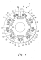
- Fig. 1 is a schematic diagram of an internal permanent magnet synchronous motor according to this invention.
- Fig. 2 is a diagram describing the form of the tooth tip part according to this invention.
- Fig. 3 is a diagram describing an inductance according to this invention.
- Fig. 4 is a schematic diagram of a second embodiment of this invention.
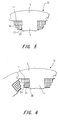
- Fig. 5 is a schematic diagram of a third embodiment of this invention.
- Fig. 6 is a schematic diagram of a fourth embodiment of this invention.
- the IPM comprises a cylindrical stator 2 comprising a coil 11, and a rotor 14 which rotates inside the stator 2.
- a stator core 3 comprises 9 sets of members 3A-3I having an identical shape arranged to form a circle.
- Each of the members 3A-3I which form the stator core 3 comprises a tooth 5 which projects toward an axial center, and base 6 which are disposed on the outer circumference of the tooth 5 and fit together.
- a projection 4A projects in the circumferential direction from one side of contact surfaces, and a depression 4B on the other contact surface fits with the projection 4A of the adjacent members 3A-3I. This prevents gaps from occurring in the radial direction of the pieces 3A-3I.
- the tooth 5 further comprise a coil winding part 5A of oblong cross-section- and a tooth tip part 5B which tapers thinner towards the axis from the coil winding part 5A.
- the coil is winded on the coil winding part 5A.
- the tooth tip part 5B need not be taper-like, and the tooth tip part 5B may become narrower in a stepwise shape towards the axis as shown in Fig.2.
- the cylindrical rotor 14 is disposed across a small air gap 12 with the inner circumference of the stator 2. This rotor 14 is supported free to rotate in a motor case to which the stator 2 is fixed.
- the rotor 14 supports a rotor core 19 formed by laminating plural doughnut-shaped steel plates in the axial direction of the shaft 16 in the same way as the stator core 3.
- the rotor 14 comprises oblong permanent magnets 17 embedded in the axial direction in six slots 15A-15F provided at equal intervals in the vicinity of the outer circumference of the rotor cores 19.
- the circumferential width of the tooth tip part 5B is smaller than the circumferential width of the coil 11 wound on the coil winding part 5A of the member 3A-3I.
- the inductance viewed from the coil 11 relative to the rotation angle of the rotor 14 is minimized when a center 51 of the permanent magnet 17 overlaps with a center 5C of the tooth tip part 5B. At this time, the reluctance viewed from the coil 11 is a maximum.
- the inductance is a maximum and magnetic losses are minimized when a midway point 52 between two adjacent permanent magnets 17 overlaps with the center 5C of the tooth tip part.
- the interval between the permanent magnets 17 of the rotor 14 be B.
- the intervals B between the permanent magnets are identical for all of the permanent magnets 17. This inductance is effectively a maximum when the permanent magnet interval B which is the interval between two adjacent permanent magnets 17, is below the tooth tip part 5B, and hardly varies until the interval B passes under the tooth tip part 5B.
- the tooth tip part has a form which extends facing the rotor, so when the rotor rotates, the distance which the magnet interval passes through in the width of the circumferential direction of the tooth tip part increases.
- the width A of the tooth tip part 5B is smaller, the distance over which the permanent magnet interval part B passes through the width A of the tooth tip part is short.
- the inductance generated by the tooth tip part of the prior art shown by a solid line is flat in the vicinity of the maximum. This is because the region where the magnet interval part B passes under the umbrella-like tooth tip part is large. In this region, the inductance is effectively a maximum and hardly varies, as described above.
- This waveform comprises harmonics, and is not a sine wave which is the preferred inductance waveform.
- the flat region in the vicinity of the maximum decreases. This is because, as the width A in the circumferential direction of the tooth tip part 5B is smaller, the distance over which the magnet interval B of the rotor 41 passes through the width A of the tooth tip part, decreases.
- the waveform of the inductance approaches the waveform of a sine wave which does not contain harmonics, which is a desirable waveform.
- the efficiency of the IPM 1 improves. Moreover, as the maximum value of the higher harmonics can be made small when controlling the current flowing through the coil 11 to be a sine wave, the effective fundamental wave component increases and the output of the IPM 1 improves.
- the rotor 14 is provided with two permanent magnet parts 22, 23 disposed in a V shape so as to form an opening towards the stator 2.
- These permanent magnet parts 22, 23 form a permanent magnet 21 having one pole.
- the permanent magnet 17 comprises one permanent magnet and its size is enlarged, the interval B between the magnets will decrease and the tooth tip width A will increase. This brings about an increase in the region in which the inductance does not vary in the vicinity of the maximum.
- the magnetic flux can be increased by forming the V-shaped magnet 21 with the two permanent magnet parts 22, 23 without increasing the width in the circumferential direction of the magnet 21. Therefore, it is not necessary to increase the interval B between the magnets and the tooth tip width A.
- the magnetic flux is concentrated toward the center of the permanent magnet 21 by making the magnetization direction of the permanent magnet parts 22, 23 perpendicular to the longitudinal direction of the permanent magnet parts 22, 23. Therefore, even if the tooth tip part 5B of the stator 2 is made thin, there is almost no effect on the torque.
- the torque of the IPM 1 is increased and harmonics can be reduced by disposing the permanent magnet parts 22, 23 in a V shape in the rotor 14 instead of the permanent magnet 17.
- An identical effect can be obtained by giving the V-shaped permanent magnet 21, a U shape.
- a protrusion 5D which projects in the direction of a circumference is provided at a boundary between the tooth tip part 5B and coil winding part 5A in order to hold the coil 11.
- the coil 11 may be installed by inserting it between the gaps between the stator teeth 5, or the coil 11 may be formed by winding copper wire directly around the coil winding part 5A.
- the tooth tip part 5B of the stator 2 is formed thinner than the coil winding part 5A, the position of the coil 11 may shift or the coil may fall out due to vibration caused by rotation of the motor. Moreover, if the coil is formed by winding copper wire directly around the coil winding part 5A, the winding position of the coil 11 is not fixed and workability is impaired.
- the shift or dropout of the coil 11 is prevented by providing the protrusion 5D at the boundary between the tooth tip part 5B and the coil winding part 5A. Workability when the copper wire is wound directly around the coil winding part 5A can be improved.
- a slot insulator 31 is formed whereby the tooth 5 holds the coil 11.
- This slot insulator cell 31 comprises a resin composition which is an insulating material having a shape of a bobbin.
Landscapes
- Engineering & Computer Science (AREA)
- Power Engineering (AREA)
- Iron Core Of Rotating Electric Machines (AREA)
- Permanent Field Magnets Of Synchronous Machinery (AREA)
- Permanent Magnet Type Synchronous Machine (AREA)
- Synchronous Machinery (AREA)
Abstract
Description
- This invention relates to an internal permanent magnet synchronous motor (IPM).
- JP2000-69717A published by the Japanese Patent Office in 2000 discloses an IPM wherein the coil end part is made more compact and the manufacturing process is simplified by concentrating coil windings in the stator.
- In this IPM, a tooth tip part spreads like an umbrella toward the motor axial center. This aims to reduce leakage of magnetic flux generated by the permanent magnet in the rotor so as to increase the motor torque. It also aims to reduce the variation of the magnetic reluctance of the permanent magnets due to rotation of the rotor, and thereby reduce distortion in the magnetic flux waveform relative to the rotor rotation angle.
- However, the inductance seen from the coil will be largely distorted from a sine waveform due to the umbrella-like expansion of the tooth tip part. Moreover, even if a sinusoidal voltage is applied to each phase of the motor coils, the current will not be a sine wave and the waveform will include harmonics. Conversely, even if current control is performed by an inverter or the like installed externally so that the current is a sine wave, harmonic components will appear in the voltage required to maintain the desired current value.
- It is therefore an object of this invention to reduce harmonic components in the voltage of an IPM. To achieve above object, an internal permanent magnetic synchronous motor of this invention comprises a cylindrical stator that comprises a tooth comprising a tooth tip part and a coil winding part around which a coil is wounded, and a rotor that has a permanent magnet and rotates inside the stator. A circumferential width of the tooth tip part on a rotor side of the tooth is smaller than a circumferential width of the coil.
- The details as well as other features and advantages of this invention are set forth in the remainder of the specification and are shown in the accompanying drawings.
- Fig. 1 is a schematic diagram of an internal permanent magnet synchronous motor according to this invention.
- Fig. 2 is a diagram describing the form of the tooth tip part according to this invention.
- Fig. 3 is a diagram describing an inductance according to this invention.
- Fig. 4 is a schematic diagram of a second embodiment of this invention.
- Fig. 5 is a schematic diagram of a third embodiment of this invention.
- Fig. 6 is a schematic diagram of a fourth embodiment of this invention.
- Referring to Fig. 1, which is a cross-sectional view of an internal permanent magnet synchronous motor (IPM) according to this invention, the IPM comprises a
cylindrical stator 2 comprising acoil 11, and arotor 14 which rotates inside thestator 2. - A stator core 3 comprises 9 sets of
members 3A-3I having an identical shape arranged to form a circle. - Each of the
members 3A-3I which form the stator core 3 comprises atooth 5 which projects toward an axial center, andbase 6 which are disposed on the outer circumference of thetooth 5 and fit together. - At the
base 6 of the stator core 3, aprojection 4A projects in the circumferential direction from one side of contact surfaces, and adepression 4B on the other contact surface fits with theprojection 4A of theadjacent members 3A-3I. This prevents gaps from occurring in the radial direction of thepieces 3A-3I. - The
tooth 5 further comprise acoil winding part 5A of oblong cross-section- and atooth tip part 5B which tapers thinner towards the axis from thecoil winding part 5A. The coil is winded on thecoil winding part 5A. - The
tooth tip part 5B need not be taper-like, and thetooth tip part 5B may become narrower in a stepwise shape towards the axis as shown in Fig.2. - On the other hand, inside the
cylindrical stator 2, thecylindrical rotor 14 is disposed across asmall air gap 12 with the inner circumference of thestator 2. Thisrotor 14 is supported free to rotate in a motor case to which thestator 2 is fixed. - The
rotor 14 supports arotor core 19 formed by laminating plural doughnut-shaped steel plates in the axial direction of theshaft 16 in the same way as the stator core 3. Therotor 14 comprises oblongpermanent magnets 17 embedded in the axial direction in sixslots 15A-15F provided at equal intervals in the vicinity of the outer circumference of therotor cores 19. - According to this invention, the circumferential width of the
tooth tip part 5B is smaller than the circumferential width of thecoil 11 wound on thecoil winding part 5A of themember 3A-3I. - Next, referring to Fig. 2, relation between the
coil 11 wound on thecoil winding part 5A of themembers 3A-3I and thepermanent magnets 17 embedded in therotor 14, will be described. - The inductance viewed from the
coil 11 relative to the rotation angle of therotor 14 is minimized when acenter 51 of thepermanent magnet 17 overlaps with a center 5C of thetooth tip part 5B. At this time, the reluctance viewed from thecoil 11 is a maximum. - Conversely, the inductance is a maximum and magnetic losses are minimized when a
midway point 52 between two adjacentpermanent magnets 17 overlaps with the center 5C of the tooth tip part. - Here, let the interval between the
permanent magnets 17 of therotor 14 be B. As thepermanent magnets 17 are disposed at equal intervals in therotor 14, the intervals B between the permanent magnets are identical for all of thepermanent magnets 17. This inductance is effectively a maximum when the permanent magnet interval B which is the interval between two adjacentpermanent magnets 17, is below thetooth tip part 5B, and hardly varies until the interval B passes under thetooth tip part 5B. - For this reason, when a sine wave current is passed through the
coil 11, ferrous loss in the iron forming thestator 2 androtor 14 increases and the motor efficiency falls. Moreover, if the current flowing the coil is controlled to be a sine wave, as it is driven at a current and voltage limited below the maximum values of the current voltage by the power supply or inverter provided externally, the effective fundamental component considering the maximum value of the highest harmonic decreases, and the motor output falls. - According to the prior art, the tooth tip part has a form which extends facing the rotor, so when the rotor rotates, the distance which the magnet interval passes through in the width of the circumferential direction of the tooth tip part increases.
- On the other hand, according to this invention, it is formed so that the width A in the circumferential direction of the tooth tip part is smaller than the width in the circumferential direction of the
coil 11. - Therefore, since the width A of the
tooth tip part 5B is smaller, the distance over which the permanent magnet interval part B passes through the width A of the tooth tip part is short. - Referring to Fig. 3, the variation of inductance relative to the rotation angle of the
rotor 14 will be described. - The inductance generated by the tooth tip part of the prior art shown by a solid line is flat in the vicinity of the maximum. This is because the region where the magnet interval part B passes under the umbrella-like tooth tip part is large. In this region, the inductance is effectively a maximum and hardly varies, as described above. This waveform comprises harmonics, and is not a sine wave which is the preferred inductance waveform.
- On the other hand, for the inductance generated by the
tooth tip part 5B of this invention shown by the broken line, the flat region in the vicinity of the maximum decreases. This is because, as the width A in the circumferential direction of thetooth tip part 5B is smaller, the distance over which the magnet interval B of the rotor 41 passes through the width A of the tooth tip part, decreases. - Thereby, the waveform of the inductance approaches the waveform of a sine wave which does not contain harmonics, which is a desirable waveform.
- Therefore, when a sinusoidal voltage is applied to the
coil 11 of the IPM 1, as increase of the core loss generated inside the steel plate forming thestator 2 androtor 14 is suppressed, the efficiency of the IPM 1 improves. Moreover, as the maximum value of the higher harmonics can be made small when controlling the current flowing through thecoil 11 to be a sine wave, the effective fundamental wave component increases and the output of the IPM 1 improves. - It might be considered that an identical effect might be obtained by making not only the
tooth tip part 5B narrow, but instead, by making the whole of thetooth 5 narrow, but in general, a greater width in the circumferential direction of thetooth 5 permits an increase of motor torque. - Therefore, in order to reduce harmonic components without having an adverse influence on the motor torque, the form of this invention where only the
tooth tip part 5B is made thin is more effective. - Next, a second embodiment of this invention will be described referring to Fig.4. According to this embodiment, instead of the
permanent magnets 17, therotor 14 is provided with twopermanent magnet parts stator 2. Thesepermanent magnet parts permanent magnet 21 having one pole. - The other constituent features are identical to those of the first embodiment. Identical reference numbers are also given to the same component parts as those of the first embodiment.
- In order to increase the torque of the IPM 1, it is necessary to increase the size of the
permanent magnet 17 embedded in therotor 14. However, if the size of thepermanent magnet 17 is made large in the direction of the circumference, it will be necessary to enlarge also the tooth tip part width A. - This is because at both ends of the
permanent magnet 17 which extend beyond thetooth 5, a self-loop or magnetic flux which shorts the adjacentpermanent magnet 17 increases. Moreover, the reluctance viewed from thepermanent magnet 17 becomes large, and the magnetic flux which thepermanent magnet 17 generates decreases. - Thus, if the
permanent magnet 17 comprises one permanent magnet and its size is enlarged, the interval B between the magnets will decrease and the tooth tip width A will increase. This brings about an increase in the region in which the inductance does not vary in the vicinity of the maximum. - According to this embodiment, the magnetic flux can be increased by forming the V-shaped
magnet 21 with the twopermanent magnet parts magnet 21. Therefore, it is not necessary to increase the interval B between the magnets and the tooth tip width A. - Moreover, as the arrow in Fig. 4 shows, the magnetic flux is concentrated toward the center of the
permanent magnet 21 by making the magnetization direction of thepermanent magnet parts permanent magnet parts tooth tip part 5B of thestator 2 is made thin, there is almost no effect on the torque. - Therefore, the torque of the IPM 1 is increased and harmonics can be reduced by disposing the
permanent magnet parts rotor 14 instead of thepermanent magnet 17. An identical effect can be obtained by giving the V-shapedpermanent magnet 21, a U shape. - Next, a third embodiment will be described referring to Fig. 5. According to this embodiment, a
protrusion 5D which projects in the direction of a circumference is provided at a boundary between thetooth tip part 5B andcoil winding part 5A in order to hold thecoil 11. - The remaining features are identical to those of the first embodiment, and identical reference numbers are given to identical parts.
- The
coil 11 may be installed by inserting it between the gaps between thestator teeth 5, or thecoil 11 may be formed by winding copper wire directly around thecoil winding part 5A. - In either of these methods, if the
tooth tip part 5B of thestator 2 is formed thinner than thecoil winding part 5A, the position of thecoil 11 may shift or the coil may fall out due to vibration caused by rotation of the motor. Moreover, if the coil is formed by winding copper wire directly around thecoil winding part 5A, the winding position of thecoil 11 is not fixed and workability is impaired. - Therefore, the shift or dropout of the
coil 11 is prevented by providing theprotrusion 5D at the boundary between thetooth tip part 5B and thecoil winding part 5A. Workability when the copper wire is wound directly around thecoil winding part 5A can be improved. - Next, a fourth embodiment of this invention will be described referring to Fig. 6. According to this embodiment, a
slot insulator 31 is formed whereby thetooth 5 holds thecoil 11. Thisslot insulator cell 31 comprises a resin composition which is an insulating material having a shape of a bobbin. - The remaining features are identical to those of the first embodiment, and identical reference numbers are given to the same component elements.
- Thereby, an identical effect to that of the fourth embodiment can be obtained.
- According to this specification, a 6 pole, 9 slot motor was described wherein there are 9 of the
tooth 5 of thestator permanent magnets 17 inside therotor 14, however the invention may also be applied to a motor comprising a different number of permanent magnets and a different number of slots. - The entire contents of Japanese Patent Application P2001-286504 (filed on September 20, 2001) are incorporated herein by reference.
- Although the invention has been described above by reference to certain embodiments of the invention, the invention is not limited to the embodiments described above. Modifications and variations of the embodiments described above will occur to those skilled in the art, in light of the above teachings. The scope of the invention is defined with reference to the following claims.
Claims (7)
- An internal permanent magnetic synchronous motor comprising:wherein a circumferential width (A) of the tooth tip part (5B) on a rotor side of the tooth is smaller than a circumferential width of the coil.a cylindrical stator (2) that comprises a tooth (5) comprising a tooth tip part (5D) and a coil winding part (5A) around which a coil (11) is wounded; anda rotor (14) that has a permanent magnet (17, 21) and rotates inside the stator,
- The internal permanent magnetic synchronous motor as defined in Claim 1, wherein the coil (11) has a concentrated winding.
- The internal permanent magnetic synchronous motor as defined in Claim1, wherein the permanent magnet (17, 21) forms a V or U-shape having an opening directed toward the stator.
- The internal permanent magnetic synchronous motor as defined in Claim1, wherein the permanent magnet (21) comprises plural parts of permanent magnet (22, 23) that are arranged to form a V or U-shape having an opening toward the stator.
- The internal permanent magnetic synchronous motor as defined in Claim1, wherein the plural parts of permanent magnet (22, 23) are magnetized in a vertical direction to a longitudinal direction of the plural parts of permanent magnet.
- The internal permanent magnetic synchronous motor as defined in Claim1, wherein, at a boundary between the tooth tip part and the coil winding part, the tooth has a protrusion (5D) that extends circumferential direction for retaining the coil.
- The internal permanent magnetic synchronous motor as defined in Claim1, wherein the tooth has a slot insulator (31) that retains the coil.
Applications Claiming Priority (2)
| Application Number | Priority Date | Filing Date | Title |
|---|---|---|---|
| JP2001286504 | 2001-09-20 | ||
| JP2001286504A JP2003092863A (en) | 2001-09-20 | 2001-09-20 | Permanent magnet embedded synchronous motor |
Publications (1)
| Publication Number | Publication Date |
|---|---|
| EP1296437A1 true EP1296437A1 (en) | 2003-03-26 |
Family
ID=19109470
Family Applications (1)
| Application Number | Title | Priority Date | Filing Date |
|---|---|---|---|
| EP02017946A Withdrawn EP1296437A1 (en) | 2001-09-20 | 2002-08-09 | Internal permanent magnet synchronous motor |
Country Status (3)
| Country | Link |
|---|---|
| US (1) | US20030052567A1 (en) |
| EP (1) | EP1296437A1 (en) |
| JP (1) | JP2003092863A (en) |
Cited By (2)
| Publication number | Priority date | Publication date | Assignee | Title |
|---|---|---|---|---|
| EP1569320A3 (en) * | 2004-02-04 | 2006-05-24 | Sanyo Denki Co., Ltd. | Interior rotor motor comprising embedded permanent magnets and method of determing the ratio of stator to rotor poles |
| WO2006095887A1 (en) * | 2005-03-11 | 2006-09-14 | Toyota Jidosha Kabushiki Kaisha | Rotor of rotating electric machine, rotating electric machine and vehicle drive apparatus |
Families Citing this family (17)
| Publication number | Priority date | Publication date | Assignee | Title |
|---|---|---|---|---|
| US7127034B1 (en) * | 2003-02-05 | 2006-10-24 | Varian Medical Systems Technologies, Inc. | Composite stator |
| US7026739B2 (en) * | 2003-05-23 | 2006-04-11 | Honda Motor Co., Ltd | Stator and insulating bobbin and a manufacturing method of the stator |
| JP2005057931A (en) * | 2003-08-06 | 2005-03-03 | Honda Motor Co Ltd | Stator |
| JP4539216B2 (en) * | 2004-07-30 | 2010-09-08 | 日産自動車株式会社 | Stator shape of switched reluctance motor |
| JP5361339B2 (en) * | 2008-11-11 | 2013-12-04 | 三菱電機株式会社 | Compressor, compressor assembly facility, and compressor assembly method |
| JP5445003B2 (en) * | 2009-09-30 | 2014-03-19 | Jfeスチール株式会社 | Stator core for electric motor |
| US8436504B2 (en) * | 2010-01-11 | 2013-05-07 | Ford Global Technologies, Llc | Stator for an electric machine |
| JP5840254B2 (en) * | 2011-12-22 | 2016-01-06 | ヤマハ発動機株式会社 | Rotating electrical machine |
| JP6095267B2 (en) * | 2012-02-24 | 2017-03-15 | 株式会社クリーンクラフト | Three-phase permanent magnet synchronous motor |
| FR2994353B1 (en) * | 2012-08-01 | 2014-08-08 | Moving Magnet Tech | OPTIMIZED ELECTRIC MOTOR WITH NARROW TOOTH |
| US10050482B2 (en) * | 2013-10-30 | 2018-08-14 | Mitsubishi Electric Corporation | Electric motor, compressor including the same, and method of manufacturing electric motor |
| EP3026798B1 (en) | 2014-11-25 | 2020-10-14 | Black & Decker Inc. | Brushless motor for a power tool |
| US10328566B2 (en) | 2015-10-14 | 2019-06-25 | Black & Decker Inc. | Brushless motor system for power tools |
| JP7306530B2 (en) * | 2018-03-27 | 2023-07-11 | 株式会社デンソー | motor |
| JP7183428B2 (en) * | 2019-08-02 | 2022-12-05 | 三菱電機株式会社 | electric motor stator core |
| JP7682709B2 (en) * | 2021-06-15 | 2025-05-26 | Ntn株式会社 | Angle detection device |
| JPWO2023228582A1 (en) * | 2022-05-27 | 2023-11-30 |
Citations (8)
| Publication number | Priority date | Publication date | Assignee | Title |
|---|---|---|---|---|
| JPH08182280A (en) * | 1994-12-26 | 1996-07-12 | Okuma Mach Works Ltd | Generator |
| DE19633209A1 (en) * | 1995-08-28 | 1997-03-06 | Papst Motoren Gmbh & Co Kg | Reducing reluctance moment or cogging of electric motor |
| JPH09322442A (en) * | 1996-05-31 | 1997-12-12 | Toshiba Corp | motor |
| US6008559A (en) * | 1997-07-22 | 1999-12-28 | Matsushita Electric Industrial Co., Ltd. | Motor using a rotor including an interior permanent magnet |
| US20010002094A1 (en) * | 1996-10-18 | 2001-05-31 | Hitachi, Ltd. And Hitachi Car Engineering Co., Ltd. | Permanent magnet electric rotating machine and electomotive vehicle using permanent magnet electric rotating machine |
| JP2001157428A (en) * | 1999-11-26 | 2001-06-08 | Mitsubishi Electric Corp | Permanent magnet type synchronous motor and elevator apparatus using the same |
| EP1130747A2 (en) * | 2000-03-03 | 2001-09-05 | Hitachi, Ltd. | Permanent magnet type electric machine for an hybrid electric vehicle |
| JP2002165428A (en) * | 2000-11-20 | 2002-06-07 | Toshiba Transport Eng Inc | Synchronous rotating machine and permanent magnet type reluctance motor |
Family Cites Families (35)
| Publication number | Priority date | Publication date | Assignee | Title |
|---|---|---|---|---|
| US519097A (en) * | 1894-05-01 | Field-magnet for electric machines | ||
| US3081412A (en) * | 1958-10-23 | 1963-03-12 | Laborde & Kupfer | Alternator armature teeth |
| NL143389B (en) * | 1965-01-13 | 1974-09-16 | Philips Nv | STEPPER MOTOR SWITCHABLE TO ASYNCHRONOUS OPERATION. |
| US3644767A (en) * | 1970-03-23 | 1972-02-22 | Sadanand Vithal Kasargod | Segmented stator |
| SE365666B (en) * | 1972-08-11 | 1974-03-25 | Asea Ab | |
| US5013953A (en) * | 1989-02-28 | 1991-05-07 | E. I. Du Pont De Nemours And Company | Stator assembly for a non-static cogging brushless DC motor and method of fabricating the same |
| US5191256A (en) * | 1989-12-15 | 1993-03-02 | American Motion Systems | Interior magnet rotary machine |
| JP3430521B2 (en) * | 1992-09-24 | 2003-07-28 | 松下電器産業株式会社 | Rotating electric machine stator |
| US5753991A (en) * | 1994-12-02 | 1998-05-19 | Hydro-Quebec | Multiphase brushless AC electric machine |
| JP2782044B2 (en) * | 1994-12-21 | 1998-07-30 | セイコー精機株式会社 | Spindle motor |
| EP0729216A3 (en) * | 1995-02-21 | 1998-03-11 | Siemens Aktiengesellschaft | Hybride excited synchronous machine |
| US5698917A (en) * | 1995-09-25 | 1997-12-16 | Glacier Rpb Inc. | Electromagnetic bearing with a stationary armature canning arrangement |
| US5672243A (en) * | 1995-11-28 | 1997-09-30 | Mosel Vitelic, Inc. | Antireflection coating for highly reflective photolithographic layers comprising chromium oxide or chromium suboxide |
| DE69735741T2 (en) * | 1996-02-23 | 2006-09-14 | Matsushita Electric Industrial Co., Ltd., Kadoma | ENGINE |
| JPH09285088A (en) * | 1996-04-12 | 1997-10-31 | Hitachi Ltd | Permanent magnet rotating electric machine and electric vehicle using the same |
| US5668430A (en) * | 1996-04-17 | 1997-09-16 | Dana Corporation | Dual-sectioned switched reluctance motor |
| FR2754953B1 (en) * | 1996-10-21 | 1999-02-26 | Moving Magnet Tech | POLYPHASE MOTOR, PARTICULARLY FOR DRIVING A DISPLAY HAND |
| DE19726352A1 (en) * | 1997-06-21 | 1999-01-07 | Wolfgang Dr Amrhein | Electric drive with magnetic bearings with concentrated windings |
| JPH11113228A (en) * | 1997-10-01 | 1999-04-23 | Toyota Autom Loom Works Ltd | Reluctance motor |
| JP3440782B2 (en) * | 1997-10-29 | 2003-08-25 | 三菱電機株式会社 | Reluctance motor and reluctance motor for driving compressor |
| KR19990040474A (en) * | 1997-11-18 | 1999-06-05 | 오상수 | Generator stator |
| JP2000152577A (en) * | 1998-11-09 | 2000-05-30 | Toyoda Mach Works Ltd | Reluctance motor |
| DE69928363T2 (en) * | 1998-12-25 | 2006-06-01 | Matsushita Electric Industrial Co., Ltd., Kadoma | Motor with embedded permanent magnets embedded in the rotor |
| JP2000245085A (en) * | 1998-12-25 | 2000-09-08 | Matsushita Electric Ind Co Ltd | motor |
| JP2000245058A (en) * | 1999-02-23 | 2000-09-08 | Nec Corp | Voltage generating circuit |
| JP2000270503A (en) * | 1999-03-17 | 2000-09-29 | Fujitsu General Ltd | Permanent magnet motor |
| IT1307198B1 (en) * | 1999-06-18 | 2001-10-29 | Askoll Holding Srl | STATOR FOR SYNCHRONOUS MOTORS WITH A POLE NUMBER GREATER THAN TWO. |
| US6509665B1 (en) * | 1999-10-25 | 2003-01-21 | Matsushita Electric Industial Co., Ltd. | Motor having stator with insulator of high heat-conductivity |
| DE69920974T2 (en) * | 1999-11-18 | 2006-03-02 | Mitsubishi Denki K.K. | DC MOTOR |
| EP1247026B1 (en) * | 1999-12-27 | 2009-09-02 | LUST ANTRIEBSTECHNIK GmbH | Magnetic bearing system |
| EP1158652B1 (en) * | 2000-05-24 | 2007-09-26 | Matsushita Electric Industrial Co., Ltd. | Motor, electric vehicle and hybrid electric vehicle |
| JP2002010547A (en) * | 2000-06-16 | 2002-01-11 | Yamaha Motor Co Ltd | Permanent magnet rotor and manufacturing method thereof |
| JP3624825B2 (en) * | 2000-12-14 | 2005-03-02 | 日産自動車株式会社 | Rotating electric machine and method of manufacturing rotating electric machine |
| US20030052563A1 (en) * | 2001-09-14 | 2003-03-20 | Karl Assmann | Electric machine |
| US6909216B2 (en) * | 2002-05-29 | 2005-06-21 | Matsushita Electric Industrial Co., Ltd. | Motor generator |
-
2001
- 2001-09-20 JP JP2001286504A patent/JP2003092863A/en active Pending
-
2002
- 2002-08-09 EP EP02017946A patent/EP1296437A1/en not_active Withdrawn
- 2002-08-15 US US10/218,587 patent/US20030052567A1/en not_active Abandoned
Patent Citations (8)
| Publication number | Priority date | Publication date | Assignee | Title |
|---|---|---|---|---|
| JPH08182280A (en) * | 1994-12-26 | 1996-07-12 | Okuma Mach Works Ltd | Generator |
| DE19633209A1 (en) * | 1995-08-28 | 1997-03-06 | Papst Motoren Gmbh & Co Kg | Reducing reluctance moment or cogging of electric motor |
| JPH09322442A (en) * | 1996-05-31 | 1997-12-12 | Toshiba Corp | motor |
| US20010002094A1 (en) * | 1996-10-18 | 2001-05-31 | Hitachi, Ltd. And Hitachi Car Engineering Co., Ltd. | Permanent magnet electric rotating machine and electomotive vehicle using permanent magnet electric rotating machine |
| US6008559A (en) * | 1997-07-22 | 1999-12-28 | Matsushita Electric Industrial Co., Ltd. | Motor using a rotor including an interior permanent magnet |
| JP2001157428A (en) * | 1999-11-26 | 2001-06-08 | Mitsubishi Electric Corp | Permanent magnet type synchronous motor and elevator apparatus using the same |
| EP1130747A2 (en) * | 2000-03-03 | 2001-09-05 | Hitachi, Ltd. | Permanent magnet type electric machine for an hybrid electric vehicle |
| JP2002165428A (en) * | 2000-11-20 | 2002-06-07 | Toshiba Transport Eng Inc | Synchronous rotating machine and permanent magnet type reluctance motor |
Non-Patent Citations (4)
| Title |
|---|
| PATENT ABSTRACTS OF JAPAN vol. 1996, no. 11 29 November 1996 (1996-11-29) * |
| PATENT ABSTRACTS OF JAPAN vol. 2000, no. 23 10 February 2001 (2001-02-10) * |
| PATENT ABSTRACTS OF JAPAN vol. 2002, no. 10 10 October 2002 (2002-10-10) * |
| PATENT ABSTRACTS OF JAPAN vol. 98, no. 4 31 March 1998 (1998-03-31) * |
Cited By (3)
| Publication number | Priority date | Publication date | Assignee | Title |
|---|---|---|---|---|
| EP1569320A3 (en) * | 2004-02-04 | 2006-05-24 | Sanyo Denki Co., Ltd. | Interior rotor motor comprising embedded permanent magnets and method of determing the ratio of stator to rotor poles |
| US7358638B2 (en) | 2004-02-04 | 2008-04-15 | Sanyo Denki Co., Ltd. | Method of determining pole arc ratio of interior permanent magnet rotary motor and interior permanent magnet rotary motor |
| WO2006095887A1 (en) * | 2005-03-11 | 2006-09-14 | Toyota Jidosha Kabushiki Kaisha | Rotor of rotating electric machine, rotating electric machine and vehicle drive apparatus |
Also Published As
| Publication number | Publication date |
|---|---|
| JP2003092863A (en) | 2003-03-28 |
| US20030052567A1 (en) | 2003-03-20 |
Similar Documents
| Publication | Publication Date | Title |
|---|---|---|
| US20030052567A1 (en) | Internal permanent magnet synchronous motor | |
| US6313558B1 (en) | Electric rotary machine having concentrated winding stator | |
| US6495941B1 (en) | Dynamo-electric machine | |
| US7598645B2 (en) | Stress distributing permanent magnet rotor geometry for electric machines | |
| US20090102314A1 (en) | Rotating electrical machinery | |
| EP0544310A2 (en) | Permanent magnet type dynamoelectric machine rotor | |
| US20090315424A1 (en) | Permanent magnet synchronous machine with shell magnets | |
| JP2006509483A (en) | Electric machines, especially brushless synchronous motors | |
| JP2012100498A (en) | Stator core | |
| WO2011007694A1 (en) | Permanent-magnet type synchronous motor | |
| US20100253178A1 (en) | Permanent-magnet synchronous motor | |
| JP2003134762A (en) | Rotating electric machine | |
| US10680475B2 (en) | Rotor for rotary electric machine | |
| US20230046567A1 (en) | Magnetic geared rotary electric machine | |
| US5744893A (en) | Brushless motor stator design | |
| JP2000041367A (en) | Hybrid excitation type synchronous machine | |
| US20030168924A1 (en) | Permanent magnet synchronous motor | |
| JP2004229404A (en) | Reluctance motor and magnet of stator for reluctance motor | |
| WO2022114176A1 (en) | Electric motor | |
| US11632004B2 (en) | Electric motor with stator | |
| WO2011062064A1 (en) | Permanent-magnet synchronous motor | |
| US20240221987A1 (en) | Apparatus for manufacturing rotor | |
| JP6824334B2 (en) | Stator and motor | |
| JPH1042497A (en) | Electric motor stator | |
| JPH1094202A (en) | Permanent magnet motor and rotor magnetizer |
Legal Events
| Date | Code | Title | Description |
|---|---|---|---|
| PUAI | Public reference made under article 153(3) epc to a published international application that has entered the european phase |
Free format text: ORIGINAL CODE: 0009012 |
|
| 17P | Request for examination filed |
Effective date: 20020809 |
|
| AK | Designated contracting states |
Kind code of ref document: A1 Designated state(s): AT BE BG CH CY CZ DE DK EE ES FI FR GB GR IE IT LI LU MC NL PT SE SK TR Designated state(s): AT BE BG CH CY CZ DE DK EE ES FI FR GB GR IE IT LI LU MC NL PT SE SK TR |
|
| AX | Request for extension of the european patent |
Extension state: AL LT LV MK RO SI |
|
| AKX | Designation fees paid |
Designated state(s): DE FR GB |
|
| STAA | Information on the status of an ep patent application or granted ep patent |
Free format text: STATUS: THE APPLICATION IS DEEMED TO BE WITHDRAWN |
|
| 18D | Application deemed to be withdrawn |
Effective date: 20080301 |