EP1296409B1 - Intégration d'antenne hyperfréquence dans une fusée d'artillerie - Google Patents
Intégration d'antenne hyperfréquence dans une fusée d'artillerie Download PDFInfo
- Publication number
- EP1296409B1 EP1296409B1 EP02292319A EP02292319A EP1296409B1 EP 1296409 B1 EP1296409 B1 EP 1296409B1 EP 02292319 A EP02292319 A EP 02292319A EP 02292319 A EP02292319 A EP 02292319A EP 1296409 B1 EP1296409 B1 EP 1296409B1
- Authority
- EP
- European Patent Office
- Prior art keywords
- rocket
- antenna
- cap
- microwave frequency
- dielectric
- Prior art date
- Legal status (The legal status is an assumption and is not a legal conclusion. Google has not performed a legal analysis and makes no representation as to the accuracy of the status listed.)
- Expired - Lifetime
Links
Images



Classifications
-
- H—ELECTRICITY
- H01—ELECTRIC ELEMENTS
- H01Q—ANTENNAS, i.e. RADIO AERIALS
- H01Q1/00—Details of, or arrangements associated with, antennas
- H01Q1/42—Housings not intimately mechanically associated with radiating elements, e.g. radome
-
- H—ELECTRICITY
- H01—ELECTRIC ELEMENTS
- H01Q—ANTENNAS, i.e. RADIO AERIALS
- H01Q1/00—Details of, or arrangements associated with, antennas
- H01Q1/27—Adaptation for use in or on movable bodies
- H01Q1/28—Adaptation for use in or on aircraft, missiles, satellites, or balloons
-
- H—ELECTRICITY
- H01—ELECTRIC ELEMENTS
- H01Q—ANTENNAS, i.e. RADIO AERIALS
- H01Q21/00—Antenna arrays or systems
-
- H—ELECTRICITY
- H01—ELECTRIC ELEMENTS
- H01Q—ANTENNAS, i.e. RADIO AERIALS
- H01Q3/00—Arrangements for changing or varying the orientation or the shape of the directional pattern of the waves radiated from an antenna or antenna system
- H01Q3/26—Arrangements for changing or varying the orientation or the shape of the directional pattern of the waves radiated from an antenna or antenna system varying the relative phase or relative amplitude of energisation between two or more active radiating elements; varying the distribution of energy across a radiating aperture
-
- H—ELECTRICITY
- H01—ELECTRIC ELEMENTS
- H01Q—ANTENNAS, i.e. RADIO AERIALS
- H01Q9/00—Electrically-short antennas having dimensions not more than twice the operating wavelength and consisting of conductive active radiating elements
- H01Q9/04—Resonant antennas
- H01Q9/0407—Substantially flat resonant element parallel to ground plane, e.g. patch antenna
Definitions
- the present invention relates to an artillery rocket comprising at least one microwave antenna.
- An artillery rocket generally has an ogival-shaped upper part ensuring the penetration of the rocket into the air.
- This part called the head of the rocket possibly has (for guidance type applications) a limited volume towards the rear of the rocket for example by equipment such as a braking device.
- the head of the rocket is protected by a cap against mechanical aggression related to the flight of the projectile equipped with the rocket.
- the cap is made of a dielectric material which, in comparison with a metallic material, slightly disturbs the operation of a microwave antenna placed under the cap.
- the head of a standard rocket has electronic components located in an area protected by the cap. The available volume for microwave antennas is limited by the cover and the area reserved for electronic components.
- a standard rocket further comprises a programming coil whose technical characteristics and position must be compatible with induction programming by means of a standard programmer which is applied to the outer vicinity of the head of the rocket.
- the document US Patent 5404145 describes a rocket comprising a microwave antenna and a dielectric having a cap.
- the subject of the invention is an artillery rocket according to claim 1.
- An advantage of the invention is in particular to allow the realization of an artillery rocket comprising two microwave antennas operating without mutual disturbance in two distinct ranges.
- FIG. 1 schematically illustrates an example of standard rocket.
- the upper part of an artillery rocket has a longitudinal section which can be represented by the diagram of FIG. 1.
- the upper part 1 of the rocket is limited towards the bottom of FIG. 1 by a device 2 which is for example a braking device comprising vanes deployable on command whose deployed positions are perpendicular to the flight in flight of the rocket and provide aerodynamic braking of the rocket.
- the upper part 1 of the rocket has upwardly an ogival shape protected by a cap 3.
- the cap 3 provides protection against mechanical attack, including erosion and heating, related to the flight of a projectile equipped with the rocket.
- An area 4 delimits an internal volume at the upper part 1 of the rocket, available for the integration of the electronic components of the rocket. This volume is generally cylindrical, for example with a symmetry of revolution about an axis 5, vertical in Figure 1, around which the rocket also has a symmetry of revolution.
- the free space between the cap 3 and the outer surface of the zone 4 allows the integration of the
- the outer surface 7 of the zone 4 is generally metallic, which makes it possible to avoid radioelectric interference between a microwave antenna of the rocket placed outside the zone 4 and the metal parts of the electronic components of said zone 4 as by example the ground plane of a printed circuit or an electromechanical component.
- the outer metal surface of the zone 4 makes it possible to define and modify the electronic components of the rocket inside this zone by avoiding the effect of their metallic parts on the radio operation of a microwave antenna of the rocket.
- a programming coil 8 is placed under the cap of the standard fuse of Figure 1 and outside the zone 4 reserved for electronic components, the coil 8 is located towards the top of the fuse between the tip 9 of the cap and the top of the outer surface of the zone 4.
- This coil 8 makes it possible to program a behavior of the rocket by means of a programming device, not shown in FIG. 1, applying to the outside of the cap 3 and having a primary coil.
- the rocket shown schematically in Figure 2b comprises a first microwave antenna 29 plane and perpendicular to the longitudinal axis 30 of the rocket.
- the first microwave antenna operates at 15 GHz and allows for example a telemetry or remote control link with the ground.
- This antenna made in the form of a large diameter disc could not be integrated into the rocket.
- FIG. 2a represents the relative footprints of a standard rocket and of a known elongated rocket comprising only in its internal volume a 1.5 GHz microwave antenna.
- the elongated rocket has an envelope 20 whose size is larger than the envelope 21 of a standard rocket.
- the elongated rocket has a head longer than the standard rocket.
- the second microwave antenna (integrated in the rocket volume) comprises two rectangular pellets 23 and 24 diametrically opposed under a cap 25. It operates at 1.5 GHz and is particularly usable for exchanging data. information with the GPS system, whose abbreviation means in English Global Positioning System.
- the pellets for example, have identical surfaces, the longest sides of each pellet having one end 26 towards the front of the rocket, situated at the top of FIG. 2b, the other end 27 being located towards the rear of the pellet. head of the rocket.
- the two pellets are mutually coupled by their rear field because they are not applied on a closed metal cone.
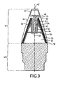
- FIG. 3 illustrates a particular embodiment of the invention comprising two microwave antennas integrated into the volume of a standard fuse.
- the lower part 40 of the rocket is not detailed.
- the upper part 41 or head of the rocket is represented by a diagram of a longitudinal section passing through the axis of symmetry 42 of the envelope of the upper part 41.
- the cap of the rocket has two parts: an upper cap 43 at the front end of the rocket and a lower cap 44 placed between the upper cap and the lower part 40 of the rocket.
- the assembly formed by the upper cap 43 and the lower cap 44 providing protection of the contents of the head of the rocket.
- the lower cap 44 is made of a dielectric material and forms the dielectric portion of a first high frequency microwave antenna, operating for example at 15 GHz.
- the lower cap 44 has an outer face 45 in the form of a truncated cone and an inner face of conical shape, the thickness of the dielectric between the inner and outer faces being greater towards the front of the rocket on the side of the upper cap and less important towards the rear side of the lower part 40 of the rocket.
- the lower cap 44 has a volume generated by a symmetry of revolution about the axis of symmetry 42 of a pants-shaped surface whose belt is on the side of the upper cap and the legs extend to the portion lower 40 of the rocket.
- the lower cap 44 has in a longitudinal sectional plane a shape substantially in pants.
- a metal surface 46 is in contact with the inner face of the lower cap 44 dielectric, it carries a ground plane of the first high frequency microwave antenna.
- the metal surface 46 has a form of revolution.
- an electric field is created in a coaxial tube 48 whose axis is common with the axis 42 of symmetry of the casing of the rocket head and which has a core 51 and a sheath or conductor external 52.
- the electric field is created symmetrically in roll.
- the coaxial tube 48 is hollow, that is to say that its core 51 is hollow and has an internal face in the form of a cylinder of revolution about the axis of symmetry 42 delimiting a space 53 allowing for example the passage of a cable for electrically powering equipment, such as for example a proxime antenna or an impact detection, protected under the upper cap 43.
- the coaxial tube 48 is solid, it has a solid cylindrical core.
- the core 51 passes through the dielectric material of the lower cap 44 to the top 49 of the truncated cone of the lower cap 44 in front of which has a metallized surface.
- the coaxial tube comprises a layer of internal dielectric material 54 which is for example made in the dielectric material of the lower cap 44.
- the internal dielectric 54 of the coaxial tube 48 forms a continuous piece with the lower cap 44.
- the electric field created, radial and symmetrical with respect to the axis of symmetry 42, is guided by the coaxial tube 48 towards the front of the rocket up to the upper limit of the sheath 52, then the electric field drives the dielectric of the first antenna. It is propagated by turning and becoming substantially parallel to the axis of symmetry 42 and then propagating radially to the outer surface of the lower cap 44 before changing further orientation to become substantially radial and propagate in the dielectric of the lower cap 44 towards the rear of the rocket.
- the field follows the dielectric whose thickness is reduced and has a form of trouser leg to exit through the narrow bottom 50 of the leg and continue its propagation in the form of surface current along the projectile carrying the rocket.
- the attack of the dielectric of the first antenna by a coaxial tube is symmetrical in roll. It has the advantage of allowing a microwave transmission at the rear of the projectile independent of the roll position of the rocket.
- the directivity of the first coaxial-etched antenna has no transmission at an angle between zero and a few degrees around the rear axis of the projectile, and shows good transmission from 1.5 to 2 degrees away of the rear axle. This transmission makes it possible, for example, to transmit a GPS code without interruption by a gyro projectile having a substantially non-zero pitch angle, especially when the projectile is far from its launching point.
- the first antenna with a dielectric forming a cap of the rocket has the advantage of allowing the field to propagate out of the antenna in a surface current with reduced leakage at the bottom 50 of the rocket.
- the first microwave antenna works better than the length of the pants is great.
- the sheath 52 extends from its upper part by a shape 55 of revolution and substantially conical within which a zone 57 is available for the integration of electronic components of the rocket.
- a ring 56 having the axis of symmetry said axis 42 is inserted inside the shape 55 at a position where the inner diameter of the revolution form 55 substantially coincides with the outer diameter of the ring 56.
- the ring 56 , the inner surface of the shape 55 and the envelope of the lower part 40 of the rocket delimit the zone 57.
- a programming coil 58 is represented by a longitudinal section in FIG. 3.
- the coil has a substantially conical shape with an axis 42.
- the coil 58 is inserted inside the cone delimited by the metal surface 46 which carries out a plan mass of the first microwave antenna, the coil being placed necessarily in the upper part, that is to say the narrowest part of this cone.
- FIG. 4 represents, with the same references as in FIG. 3, a view in developed along the axis of symmetry 42, the dielectric of the first microwave antenna with lower cap 44, the metal surface 46 of the first microwave antenna, the coil 58, the shape 55 and ring 56. These various elements fit into each other in the order of enumeration, the cap 44 protecting the whole.
- the first antenna is not attacked by a coaxial tube but by a circuit comprising one or more microwave pads placed at the top 49 of the truncated cone of the dielectric of the antenna forming the lower cap. 44, a dielectric circuit thickness along the axis 42 and a ground plane of the circuit perpendicular to the axis 42, the top side of the rocket.
- the pellet is, for example, in the form of a symmetrical ring along the axis of symmetry 42.
- pellets of substantially square shape are placed at the top 49, either two diametrically opposed pellets, or larger pellets regularly distributed around of the axis of symmetry.
- the number of pellets is preferably less than eight.
- the limitation of the number of pellets leads to an emission exhibiting a variable behavior according to the roll of the rocket and the emission towards the ground is not constant.
- the circuit preferably has a ring shape which ensures the emission stable behavior despite a variable roll.
- the radial length of the pellets is limited by the radius of the top 49 of the truncated cone.
- the pellet (s) operate either in half-wavelength with a high permittivity dielectric, or in quarter-wavelength with a lower permittivity dielectric. For the first operation impedance matching is easier to achieve because the accuracy of the position of the power supply is less critical.
- the antenna When the feed points of said driver circuit of the first antenna are in phase, the antenna has the advantage of allowing transmission to the rear of the projectile carrying the rocket in a fairly wide angular field, typically between 2 and 30 degrees relative to the axis of symmetry 42.
- the transmission is relatively close to that obtained with an attack by a coaxial tube.
- the transmission is essentially in the rear axis of the projectile.
- This embodiment is advantageous for a remote control at the beginning of the trajectory of the projectile.
- a second microwave antenna 47 shown in FIG. 3, operating at a lower frequency than the first antenna, for example at 1.5 GHz, is embedded in the metal surface 46 of the ground plane of the first antenna, on the inner face side.
- the second microwave antenna thus placed on the inner face of the dielectric of the first microwave antenna has a reduced discomfort in the operation of this first antenna.
- the length of the second antenna measured along the axis of symmetry 42 is limited to a value slightly less than the height of the lower cap 44, taking care to respect this limitation the second antenna can be of half-length type. wave with a high permittivity dielectric, or quarter-wavelength type with a lower permittivity dielectric (the ratio of the permittivity is 4).
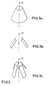
- FIGS. 5a, 5b and 5c show three exemplary embodiments of the second antenna represented with respect to the axis of symmetry already referenced 42 in FIG. 3.
- the antenna of FIG. 5a has a symmetrical cone shape with respect to FIG. 42 axis, it has a symmetry in roll ensuring a substantially constant transmission during the rotation of the projectile on itself.
- a second antenna having two or four pellets is shown respectively in Figures 5b and 5c.
- the number of pellets of the second antenna is preferably limited to four, this limitation ensuring integration of the antenna in the rocket easier.
- the number of pellets may be greater than four.
- the composite signal received thus corresponds to the emission of the fields by each pellet.
- the coil 58 in FIG. 3 is placed relative to the outside of the rocket under the ground plane 46 of the first antenna which is also that of the second antenna 47.
- the operation of the antenna or antennas of the rocket is not disturbed by the coil.
- the presence of the thin metal walls (46 and the pellets of the second antenna, the thickness of which is preferably less than 150 ⁇ m and whose production is carried out for example by screen printing on the dielectric) allows the coupling with a programming transformer with limited attenuation.
- the programming transformer is placed during the programming operation around the rocket cap. The position and the dimension of the coil make it possible to respect a reduced distance with respect to the external surface of the cap.
Landscapes
- Physics & Mathematics (AREA)
- Engineering & Computer Science (AREA)
- Astronomy & Astrophysics (AREA)
- Aviation & Aerospace Engineering (AREA)
- General Physics & Mathematics (AREA)
- Remote Sensing (AREA)
- Details Of Aerials (AREA)
- Organic Low-Molecular-Weight Compounds And Preparation Thereof (AREA)
- Variable-Direction Aerials And Aerial Arrays (AREA)
Description
- La présente invention concerne une fusée d'artillerie comportant au moins une antenne hyperfréquence.
- Une fusée d'artillerie présente généralement une partie supérieure de forme ogivale assurant la pénétration de la fusée dans l'air. Cette partie appelée tête de la fusée présente éventuellement (pour des applications de type guidage) un volume limité vers l'arrière de la fusée par exemple par un équipement tel qu'un dispositif de freinage. Dans une fusée standard la tête de la fusée est protégée par une coiffe contre les agressions mécaniques liées au vol du projectile équipé de la fusée. La coiffe est réalisée dans un matériau diélectrique qui, par comparaison avec un matériau métallique, perturbe peu le fonctionnement d'une antenne hyperfréquence placée sous la coiffe. La tête d'une fusée standard comporte des composants électroniques situés dans une zone protégée par la coiffe. Le volume disponible pour des antennes hyperfréquence est limité par la coiffe et par la zone réservée aux composants électroniques.
- Une fusée standard comporte en outre une bobine de programmation dont les caractéristiques techniques et la position doivent être compatibles d'une programmation par induction au moyen d'un programmateur standard venant s'appliquer au voisinage extérieur de la tête de la fusée.
- Le document
US-A-5404145 décrit une fusée comportant une antenne hyperfréquence et un diélectrique faisant coiffe. - L'invention a pour objet une fusée d'artillerie selon la revendication 1.
- Un avantage de l'invention est notamment de permettre la réalisation d'une fusée d'artillerie comportant deux antennes hyperfréquence fonctionnant sans perturbation mutuelle dans deux gammes distinctes.
- D'autres caractéristiques et avantages de l'invention apparaîtront à l'aide de la description qui suit faite en regard de dessins annexés qui représentent :
- la figure 1, un exemple de fusée standard ;
- la figure 2, un exemple de fusée allongée comportant une antenne hyperfréquence à 1.5 GHz dans lequel la figure 2a illustre l'encombrement de la fusée allongée par rapport à une fusée standard et la figure 2b représente une coupe longitudinale de la fusée allongée ;
- la figure 3, un exemple de réalisation de l'invention ;
- la figure 4, une vue en développé comportant une première antenne hyperfréquence selon l'invention ;
- la figure 5, trois exemples d'une seconde antenne hyperfréquence selon l'invention, une antenne anneau en figure 5a, une antenne à 2 et 4 pastilles en figures 5b et 5c.
- La figure 1 illustre de façon schématique un exemple de fusée standard. La partie supérieure d'une fusée d'artillerie présente une coupe longitudinale qui peut être représentée par le schéma de la figure 1. La partie supérieure 1 de la fusée est limitée vers le bas de la figure 1 par un équipement 2 qui est par exemple un dispositif de freinage comportant des ailettes déployables sur commande dont les positions déployées sont perpendiculaires au déplacement en vol de la fusée et permettent d'assurer un freinage aérodynamique de la fusée. La partie supérieure 1 de la fusée présente vers le haut une forme ogivale protégée par une coiffe 3. La coiffe 3 assure une protection contre les agressions mécaniques, notamment l'érosion et l'échauffement, liées au vol d'un projectile équipé de la fusée. Une zone 4 délimite un volume interne à la partie supérieure 1 de la fusée, disponible pour l'intégration des composants électroniques de la fusée. Ce volume est généralement cylindrique, par exemple avec une symétrie de révolution autour d'un axe 5, vertical sur la figure 1, autour duquel la fusée présente également une symétrie de révolution. L'espace libre entre la coiffe 3 et la surface externe de la zone 4 permet l'intégration des antennes hyperfréquence.
- La surface externe 7 de la zone 4 est généralement métallique, ce qui permet d'éviter les interférences radioélectriques entre une antenne hyperfréquence de la fusée placée à l'extérieur de la zone 4 et les parties métalliques des composants électroniques de ladite zone 4 comme par exemple le plan de masse d'un circuit imprimé ou un composant électromécanique. La surface extérieure métallique de la zone 4 permet de définir et de modifier les composants électroniques de la fusée à l'intérieur de cette zone en s'affranchissant de l'effet de leurs parties métalliques sur le fonctionnement radioélectrique d'une antenne hyperfréquence de la fusée.
- Une bobine de programmation 8 est placée sous la coiffe de la fusée standard de la figure 1 et à l'extérieur de la zone 4 réservée aux composants électroniques, la bobine 8 est située vers le haut de la fusée entre la pointe 9 de la coiffe et le haut de la surface extérieure de la zone 4. Cette bobine 8 permet de programmer un comportement de la fusée au moyen d'un dispositif de programmation, non représenté sur la figure 1, s'appliquant à l'extérieur de la coiffe 3 et comportant une bobine primaire.
- La fusée schématisée sur la figure 2b comporte une première antenne hyperfréquence 29 plane et perpendiculaire à l'axe longitudinal 30 de la fusée. Dans cet exemple, la première antenne hyperfréquence fonctionne à 15 GHz et permet par exemple une liaison de télémesure ou de télécommande avec le sol. Cette antenne réalisée sous forme d'un disque de grand diamètre n'a pu être intégrée dans la fusée.
- La figure 2a représente les encombrements relatifs d'une fusée standard et d'une fusée allongée connue comportant uniquement dans son volume interne une antenne hyperfréquence à 1.5 GHz. La fusée allongée présente une enveloppe 20 dont l'encombrement est plus important que l'enveloppe 21 d'une fusée standard. Selon l'axe longitudinal 22 commun sur la figure 2a aux deux enveloppes 20, 21, la fusée allongée présente une tête plus longue que la fusée standard.
- Dans l'exemple illustré par la figure 2b, la seconde antenne hyperfréquence (intégrée dans le volume de la fusée) comporte deux pastilles rectangulaires 23 et 24 diamétralement opposées sous une coiffe 25. Elle fonctionne à 1.5 GHz et est notamment utilisable pour échanger des informations avec le système GPS, dont l'abréviation signifie en anglais Global Positionning System. Les pastilles présentent par exemple des surfaces identiques, les côtés les plus longs de chaque pastille présentant une extrémité 26 vers l'avant de la fusée, situé en haut de la figure 2b, l'autre extrémité 27 étant située vers l'arrière de la tête de la fusée. Dans cet exemple, les deux pastilles sont couplées mutuellement par leur champ arrière car elles ne sont pas appliquées sur un cône métallique fermé.
- La figure 3 illustre une réalisation particulière de l'invention comportant deux antennes hyperfréquence intégrées dans le volume d'une fusée standard.
- La partie inférieure 40 de la fusée n'est pas détaillée. La partie supérieure 41 ou tête de la fusée est représentée par un schéma d'une coupe longitudinale passant par l'axe de symétrie 42 de l'enveloppe de la partie supérieure 41.
- La coiffe de la fusée comporte deux parties : une coiffe supérieure 43 à l'extrémité avant de la fusée et une coiffe inférieure 44 placée entre la coiffe supérieure et la partie inférieure 40 de la fusée. L'ensemble formé par la coiffe supérieure 43 et par la coiffe inférieure 44 assurant la protection du contenu de la tête de la fusée.
- La coiffe inférieure 44 est réalisée dans un matériau diélectrique et forme la partie diélectrique d'une première antenne hyperfréquence haute fréquence, fonctionnant par exemple à 15 GHz. La coiffe inférieure 44 présente une face externe 45 en forme de cône tronqué et une face interne de forme conique, l'épaisseur du diélectrique entre les faces interne et externe étant plus importante vers l'avant de la fusée du côté de la coiffe supérieure et moins importante vers l'arrière du côté de la partie inférieure 40 de la fusée. La coiffe inférieure 44 présente un volume engendré par une symétrie de révolution autour de l'axe de symétrie 42 d'une surface en forme de pantalon dont la ceinture est du côté de la coiffe supérieure et les jambes s'étendent jusqu'à la partie inférieure 40 de la fusée. La coiffe inférieure 44 présente dans un plan de coupe longitudinal une forme sensiblement en pantalon.
- Une surface métallique 46 est en contact avec la face interne de la coiffe inférieure 44 en diélectrique, elle réalise un plan de masse de la première antenne hyperfréquence haute fréquence. La surface métallique 46 présente une forme de révolution.
- Dans cet exemple de réalisation, un champ électrique est créé dans un tube coaxial 48 dont l'axe est commun avec l'axe 42 de symétrie de l'enveloppe de la tête de la fusée et qui présente une âme 51 et une gaine ou conducteur externe 52. Le champ électrique est créé symétriquement en roulis. Dans la réalisation particulière de l'invention illustrée par la figure 3, le tube coaxial 48 est creux, c'est-à-dire que son âme 51 est creuse et présente une face interne en forme de cylindre de révolution autour de l'axe de symétrie 42 délimitant un espace 53 permettant par exemple le passage d'un câble pour alimenter électriquement un équipement, comme par exemple une antenne proximètre ou une détection d'impact, protégé sous la coiffe supérieure 43. Dans une variante de réalisation de l'invention, le tube coaxial 48 est plein, il présente une âme cylindrique pleine.
- L'âme 51 traverse le matériau diélectrique de la coiffe inférieure 44 jusqu'au sommet 49 du tronc de cône de la coiffe inférieure 44 à l'avant lequel présente une surface métallisée. Entre l'âme 51 et la gaine 52, le tube coaxial comporte une couche de matériau diélectrique interne 54 qui est par exemple réalisée dans le matériau diélectrique de la coiffe inférieure 44. Dans la réalisation particulière de la figure 3, le diélectrique interne 54 du tube coaxial 48 forme une pièce continue avec la coiffe inférieure 44.
- Le champ électrique créé, radial et symétrique par rapport à l'axe de symétrie 42, est guidé par le tube coaxial 48 vers l'avant de la fusée jusqu'à la limite supérieure de la gaine 52, puis le champ électrique attaque le diélectrique de la première antenne. Il s'y propage en tournant et devenant sensiblement parallèle à l'axe de symétrie 42 puis en se propageant radialement vers la surface externe de la coiffe inférieure 44 avant de changer encore d'orientation pour redevenir sensiblement radial et se propager dans le diélectrique de la coiffe inférieure 44 vers l'arrière de la fusée. Le champ suit le diélectrique dont l'épaisseur se réduit et présente une forme de jambe de pantalon pour sortir par le bas étroit 50 de la jambe et poursuivre sa propagation sous forme de courant de surface le long du projectile portant la fusée.
- L'attaque du diélectrique de la première antenne par un tube coaxial est symétrique en roulis. Elle présente l'avantage de permettre une transmission hyperfréquence à l'arrière du projectile indépendante de la position en roulis de la fusée. La directivité de la première antenne attaquée par coaxial présente une absence de transmission pour un angle compris entre zéro et quelques degrés autour de l'axe arrière du projectile, elle présente une bonne transmission à partir de 1,5 à 2 degrés en s'éloignant de l'axe arrière. Cette transmission permet par exemple une émission d'un code GPS sans coupure par un projectile gyroscopé présentant un angle de tangage sensiblement non nul notamment lorsque le projectile est loin de son point de lancement.
- La première antenne avec un diélectrique formant coiffe de la fusée présente l'avantage de permettre la propagation du champ hors de l'antenne en un courant de surface avec des fuites réduites au bas 50 de la fusée. La première antenne hyperfréquence fonctionne d'autant mieux que la longueur du pantalon est grande.
- Sur la figure 3, la gaine 52 se prolonge à partir de sa partie supérieure par une forme 55 de révolution et sensiblement conique à l'intérieur de laquelle une zone 57 est disponible pour l'intégration de composants électroniques de la fusée. Un anneau 56 ayant pour axe de symétrie ledit axe 42 est inséré à l'intérieur de la forme 55 à une position où le diamètre intérieur de la forme de révolution 55 coïncide sensiblement avec le diamètre extérieur de l'anneau 56. L'anneau 56, la surface interne de la forme 55 et l'enveloppe de la partie inférieure 40 de la fusée délimitent la zone 57.
- Une bobine de programmation 58 est représentée par une coupe longitudinale sur la figure 3. La bobine présente une forme sensiblement conique, d'axe 42. La bobine 58 est insérée à l'intérieur du cône délimité par la surface métallique 46 qui réalise un plan de masse de la première antenne hyperfréquence, la bobine étant placée obligatoirement en partie supérieure, c'est-à-dire la partie la plus étroite, de ce cône.
- La figure 4 représente, avec les mêmes références que sur la figure 3, une vue en développé selon l'axe de symétrie 42, le diélectrique de la première antenne hyperfréquence faisant coiffe inférieure 44, la surface métallique 46 de la première antenne hyperfréquence, la bobine 58, la forme 55 et l'anneau 56. Ces divers éléments s'emboîtent les uns dans les autres dans l'ordre d'énumération, la coiffe 44 protégeant le tout.
- Dans une variante de réalisation de l'invention, la première antenne n'est pas attaquée par un tube coaxial mais par un circuit comportant une ou plusieurs pastilles hyperfréquence placées au sommet 49 du tronc de cône du diélectrique de l'antenne formant la coiffe inférieure 44, une épaisseur de diélectrique de circuit suivant l'axe 42 et un plan de masse du circuit perpendiculaire à l'axe 42, du côté du haut de la fusée. La pastille est par exemple en forme d'anneau symétrique selon l'axe de symétrie 42. Dans un autre exemple des pastilles de forme sensiblement carrée sont placées au sommet 49, soit deux pastilles diamétralement opposées, soit des pastilles en nombre supérieur réparties régulièrement autour de l'axe de symétrie. Le nombre de pastilles est de préférence inférieur à huit. La limitation du nombre de pastilles conduit à une émission présentant un comportement variable selon le roulis de la fusée et l'émission vers le sol n'est pas constante. Le circuit présente de préférence une forme en anneau qui assure à l'émission un comportement stable malgré un roulis variable. La longueur radiale des pastilles est limitée par le rayon du sommet 49 du tronc de cône. La ou les pastilles fonctionnent soit en demi-longueur d'onde avec un diélectrique de permittivité élevé, soit en quart de longueur d'onde avec un diélectrique de permittivité plus faible. Pour le premier fonctionnement l'adaptation d'impédance est plus facile à réaliser car la précision de la position de l'alimentation est moins critique.
- Lorsque les points d'alimentation dudit circuit d'attaque de la première antenne sont en phase, l'antenne présente l'avantage de permettre une transmission à l'arrière du projectile portant la fusée dans un champ angulaire assez large, typiquement entre 2 et 30 degrés par rapport à l'axe de symétrie 42. La transmission est relativement proche de celle obtenue avec une attaque par un tube coaxial.
- Lorsque les points d'alimentation dudit circuit d'attaque de la première antenne sont en déphasage, par exemple une alimentation de deux pastilles déphasées de 180 degrés, la transmission est essentiellement dans l'axe arrière du projectile. Cette réalisation est avantageuse pour une télécommande en début de trajectoire du projectile.
- Une seconde antenne hyperfréquence 47, représentée sur la figure 3, fonctionnant en fréquence plus basse que la première antenne, par exemple à 1.5 GHz, est incrustée dans la surface métallique 46 du plan de masse de la première antenne, du côté de la face interne de la coiffe inférieure 44. La seconde antenne hyperfréquence ainsi placée sur la face interne du diélectrique de la première antenne hyperfréquence présente une gêne réduite dans le fonctionnement de cette première antenne. La longueur de la seconde antenne mesurée le long de l'axe de symétrie 42 est limitée à une valeur légèrement inférieure à la hauteur de la coiffe inférieure 44, en veillant à respecter cette limitation la seconde antenne peut être de type demi-longueur d'onde avec un diélectrique de permittivité élevée, ou de type quart de longueur d'onde avec un diélectrique de permittivité plus faible (le rapport des permittivité est de 4).
- Les figures 5a, 5b et 5c représentent trois exemples de réalisation de la seconde antenne représentée par rapport à l'axe de symétrie déjà référencé 42 dans la figure 3. L'antenne de la figure 5a présente une forme de cône symétrique par rapport à l'axe 42, elle présente une symétrie en roulis assurant une transmission sensiblement constante lors de la rotation du projectile sur lui-même.
- Une seconde antenne comportant deux ou quatre pastilles est représentée respectivement sur les figures 5b et 5c. Le nombre de pastilles de la seconde antenne est de préférence limité à quatre, cette limitation assurant une intégration de l'antenne dans la fusée plus aisée. Le nombre de pastilles peut être supérieur à quatre.
- Il est possible d'alimenter l'antenne avec une entrée unique pour toutes les pastilles et une répartition symétrique des lignes d'alimentation. Le signal composite reçu (signal GPS) correspond ainsi à l'émission des champs par chaque pastille.
- Il est encore possible d'utiliser les pastilles de façon indépendante, en couplant par exemple chaque pastille à une voie de réception. Cette configuration permet notamment de recevoir correctement des signaux de satellites « côté ciel » sur une pastille alors que la pastille opposée est en vision avec le sol et peut être saturée par un brouilleur. Un brouilleur au sol ne peut transmettre que vers une antenne dirigée vers lui car à cette fréquence les antennes sont relativement directives. Ce type de configuration optimale d'intégration des antennes dans une fusée d'artillerie possède donc aussi une immunité au brouillage GPS sol, le plus probable au plan opérationnel de l'artillerie.
- La bobine 58 sur la figure 3 est placée par rapport à l'extérieur de la fusée sous le plan de masse 46 de la première antenne qui est aussi celui de la seconde antenne 47. Le fonctionnement de la ou des antennes de la fusée n'est pas perturbé par la bobine. La présence des parois métalliques fines (46 et les pastilles de la seconde antenne, dont l'épaisseur est de préférence inférieure à 150 µm et dont la réalisation s'effectue par exemple par sérigraphie sur le diélectrique) autorise le couplage avec un transformateur de programmation avec une atténuation limitée. Le transformateur de programmation est placé pendant l'opération de programmation autour de la coiffe de la fusée. La position et la dimension de la bobine permettent de respecter une distance réduite par rapport à la surface externe de la coiffe.
Claims (9)
- Fusée comportant au moins une antenne hyperfréquence, l'antenne comportant un diélectrique faisant coiffe (44) de la fusée, caractérisée en ce que le diélectrique, présente dans un plan de coupe longitudinal une forme sensiblement en pantalon ayant une symétrie de révolution autour de l'axe de symétrie (42) de la fusée.
- Fusée selon la revendication 1, caractérisée en ce que l'antenne hyperfréquence comporte un tube coaxial (48).
- Fusée selon l'une des revendications précédentes, caractérisée en ce que l'antenne hyperfréquence comporte un tube coaxial creux.
- Fusée selon la revendication 1, caractérisée en ce que l'antenne hyperfréquence comporte au moins une pastille hyperfréquence.
- Fusée selon la revendication 4, caractérisée en ce que l'antenne hyperfréquence comporte une pastille hyperfréquence en forme d'anneau.
- Fusée selon la revendication 4, caractérisée en ce que l'antenne hyperfréquence comporte 2 à 6 pastilles hyperfréquence.
- Fusée selon l'une des revendications 4 à 6, caractérisée en ce que la ou les pastilles comportant des points d'alimentation, les points d'alimentation sont à déphasage.
- Fusée selon l'une des revendications 4 à 6, caractérisée en ce que la ou les pastilles comportant des points d'alimentation, les points d'alimentation sont en phase.
- Fusée selon l'une des revendications précédentes caractérisée en ce qu'elle comporte une seconde antenne hyperfréquence incrustée dans une surface métallique (46) faisant plan de masse pour la première antenne.
Applications Claiming Priority (2)
| Application Number | Priority Date | Filing Date | Title |
|---|---|---|---|
| FR0112221A FR2830130B1 (fr) | 2001-09-21 | 2001-09-21 | Integration d'antenne hyperfrequence dans une fusee d'artillerie |
| FR0112221 | 2001-09-21 |
Publications (2)
| Publication Number | Publication Date |
|---|---|
| EP1296409A1 EP1296409A1 (fr) | 2003-03-26 |
| EP1296409B1 true EP1296409B1 (fr) | 2007-08-15 |
Family
ID=8867520
Family Applications (1)
| Application Number | Title | Priority Date | Filing Date |
|---|---|---|---|
| EP02292319A Expired - Lifetime EP1296409B1 (fr) | 2001-09-21 | 2002-09-20 | Intégration d'antenne hyperfréquence dans une fusée d'artillerie |
Country Status (5)
| Country | Link |
|---|---|
| EP (1) | EP1296409B1 (fr) |
| AT (1) | ATE370526T1 (fr) |
| DE (1) | DE60221765T2 (fr) |
| ES (1) | ES2291426T3 (fr) |
| FR (1) | FR2830130B1 (fr) |
Family Cites Families (5)
| Publication number | Priority date | Publication date | Assignee | Title |
|---|---|---|---|---|
| JPS6313505A (ja) * | 1986-07-04 | 1988-01-20 | Nec Corp | 全方向性アンテナ |
| AU4411289A (en) * | 1988-10-19 | 1990-05-14 | Toyo Communication Equipment Co., Ltd. | Array antenna and a feeder device therefor |
| US5400040A (en) * | 1993-04-28 | 1995-03-21 | Raytheon Company | Microstrip patch antenna |
| US5404145A (en) * | 1993-08-24 | 1995-04-04 | Raytheon Company | Patch coupled aperature array antenna |
| GB0002935D0 (en) * | 2000-02-10 | 2000-03-29 | Koninkl Philips Electronics Nv | Portable device antenna |
-
2001
- 2001-09-21 FR FR0112221A patent/FR2830130B1/fr not_active Expired - Lifetime
-
2002
- 2002-09-20 DE DE60221765T patent/DE60221765T2/de not_active Expired - Lifetime
- 2002-09-20 ES ES02292319T patent/ES2291426T3/es not_active Expired - Lifetime
- 2002-09-20 AT AT02292319T patent/ATE370526T1/de active
- 2002-09-20 EP EP02292319A patent/EP1296409B1/fr not_active Expired - Lifetime
Non-Patent Citations (1)
| Title |
|---|
| None * |
Also Published As
| Publication number | Publication date |
|---|---|
| EP1296409A1 (fr) | 2003-03-26 |
| ES2291426T3 (es) | 2008-03-01 |
| DE60221765D1 (de) | 2007-09-27 |
| FR2830130A1 (fr) | 2003-03-28 |
| FR2830130B1 (fr) | 2005-05-06 |
| ATE370526T1 (de) | 2007-09-15 |
| DE60221765T2 (de) | 2008-06-05 |
Similar Documents
| Publication | Publication Date | Title |
|---|---|---|
| EP3725002B1 (fr) | Detecteur double technologie a bobines transverses | |
| EP3171451B1 (fr) | Combineur spatial de puissance | |
| WO2005036697A1 (fr) | Antenne interne de faible volume | |
| EP1489688B1 (fr) | Alimentation pour une antenne a reflecteur | |
| EP3109941B1 (fr) | Antenne micro onde à double réflecteur | |
| WO2010121851A1 (fr) | Antenne multiple large bande a faible profil | |
| EP2416449A1 (fr) | Antenne à réflecteur parabolique | |
| FR2903234A1 (fr) | Element parasite pour antenne helicoidale. | |
| FR2687013A1 (fr) | Aerien pour radar. | |
| EP0860893A1 (fr) | Ensemble d'antennes concentriques pour des ondes hyperfréquences | |
| EP1350285B1 (fr) | Sonde electromagnetique | |
| EP0860894B1 (fr) | Antenne miniature résonnante de type microruban de forme annulaire | |
| EP1296409A1 (fr) | Intégration d'antenne hyperfréquence dans une fusée d'artillerie | |
| FR2969829A1 (fr) | Antenne de forte puissance large bande | |
| Hinostroza | Design of wideband arrays of spiral antennas. | |
| FR2760133A1 (fr) | Antenne resonnante pour l'emission ou la reception d'ondes polarisees | |
| CA3085487A1 (fr) | Detecteur double technologie a bobines transverses | |
| EP2449629B1 (fr) | Systeme antennaire compacte omnidirectionnel et large bande comportant deux acces emission et reception separes fortement decouples | |
| EP2946435B1 (fr) | Antenne à guide d'onde miniaturisee | |
| EP0047684A1 (fr) | Antenne pour missile et missile comprenant une telle antenne | |
| WO2016139403A1 (fr) | Structure antennaire omnidirectionnelle large bande | |
| FR3022405A1 (fr) | Antenne plate de telecommunication par satellite | |
| FR3157020A1 (fr) | Antenne omnidirectionnelle et ensemble antennaire associé. | |
| FR2699268A1 (fr) | Agencement détecteur pour munition. | |
| FR2522884A1 (fr) | Joint tournant haute frequence |
Legal Events
| Date | Code | Title | Description |
|---|---|---|---|
| PUAI | Public reference made under article 153(3) epc to a published international application that has entered the european phase |
Free format text: ORIGINAL CODE: 0009012 |
|
| AK | Designated contracting states |
Kind code of ref document: A1 Designated state(s): AT BE BG CH CY CZ DE DK EE ES FI FR GB GR IE IT LI LU MC NL PT SE SK TR Designated state(s): AT BE BG CH CY CZ DE DK EE ES FI FR GB GR IE IT LI LU MC NL PT SE SK TR |
|
| AX | Request for extension of the european patent |
Extension state: AL LT LV MK RO SI |
|
| 17P | Request for examination filed |
Effective date: 20030918 |
|
| AKX | Designation fees paid |
Designated state(s): AT BE BG CH CY CZ DE DK EE ES FI FR GB GR IE IT LI LU MC NL PT SE SK TR |
|
| GRAP | Despatch of communication of intention to grant a patent |
Free format text: ORIGINAL CODE: EPIDOSNIGR1 |
|
| GRAS | Grant fee paid |
Free format text: ORIGINAL CODE: EPIDOSNIGR3 |
|
| GRAA | (expected) grant |
Free format text: ORIGINAL CODE: 0009210 |
|
| RAP1 | Party data changed (applicant data changed or rights of an application transferred) |
Owner name: THALES MUNITRONICS & MICROTECHNICS SAS |
|
| AK | Designated contracting states |
Kind code of ref document: B1 Designated state(s): AT BE BG CH CY CZ DE DK EE ES FI FR GB GR IE IT LI LU MC NL PT SE SK TR |
|
| REG | Reference to a national code |
Ref country code: GB Ref legal event code: FG4D Free format text: NOT ENGLISH |
|
| PGFP | Annual fee paid to national office [announced via postgrant information from national office to epo] |
Ref country code: MC Payment date: 20070828 Year of fee payment: 6 |
|
| REG | Reference to a national code |
Ref country code: CH Ref legal event code: EP |
|
| REG | Reference to a national code |
Ref country code: IE Ref legal event code: FG4D Free format text: LANGUAGE OF EP DOCUMENT: FRENCH |
|
| REF | Corresponds to: |
Ref document number: 60221765 Country of ref document: DE Date of ref document: 20070927 Kind code of ref document: P |
|
| REG | Reference to a national code |
Ref country code: SE Ref legal event code: TRGR |
|
| GBT | Gb: translation of ep patent filed (gb section 77(6)(a)/1977) |
Effective date: 20071121 |
|
| PG25 | Lapsed in a contracting state [announced via postgrant information from national office to epo] |
Ref country code: FI Free format text: LAPSE BECAUSE OF FAILURE TO SUBMIT A TRANSLATION OF THE DESCRIPTION OR TO PAY THE FEE WITHIN THE PRESCRIBED TIME-LIMIT Effective date: 20070815 Ref country code: NL Free format text: LAPSE BECAUSE OF FAILURE TO SUBMIT A TRANSLATION OF THE DESCRIPTION OR TO PAY THE FEE WITHIN THE PRESCRIBED TIME-LIMIT Effective date: 20070815 Ref country code: BG Free format text: LAPSE BECAUSE OF FAILURE TO SUBMIT A TRANSLATION OF THE DESCRIPTION OR TO PAY THE FEE WITHIN THE PRESCRIBED TIME-LIMIT Effective date: 20071115 |
|
| PGFP | Annual fee paid to national office [announced via postgrant information from national office to epo] |
Ref country code: NL Payment date: 20070903 Year of fee payment: 6 |
|
| NLV1 | Nl: lapsed or annulled due to failure to fulfill the requirements of art. 29p and 29m of the patents act | ||
| REG | Reference to a national code |
Ref country code: ES Ref legal event code: FG2A Ref document number: 2291426 Country of ref document: ES Kind code of ref document: T3 |
|
| BERE | Be: lapsed |
Owner name: THALES MUNITRONICS & MICROTECHNICS SAS Effective date: 20070930 |
|
| REG | Reference to a national code |
Ref country code: IE Ref legal event code: FD4D |
|
| PG25 | Lapsed in a contracting state [announced via postgrant information from national office to epo] |
Ref country code: DK Free format text: LAPSE BECAUSE OF FAILURE TO SUBMIT A TRANSLATION OF THE DESCRIPTION OR TO PAY THE FEE WITHIN THE PRESCRIBED TIME-LIMIT Effective date: 20070815 Ref country code: GR Free format text: LAPSE BECAUSE OF FAILURE TO SUBMIT A TRANSLATION OF THE DESCRIPTION OR TO PAY THE FEE WITHIN THE PRESCRIBED TIME-LIMIT Effective date: 20071116 |
|
| REG | Reference to a national code |
Ref country code: CH Ref legal event code: PL |
|
| PG25 | Lapsed in a contracting state [announced via postgrant information from national office to epo] |
Ref country code: PT Free format text: LAPSE BECAUSE OF FAILURE TO SUBMIT A TRANSLATION OF THE DESCRIPTION OR TO PAY THE FEE WITHIN THE PRESCRIBED TIME-LIMIT Effective date: 20080115 Ref country code: IE Free format text: LAPSE BECAUSE OF FAILURE TO SUBMIT A TRANSLATION OF THE DESCRIPTION OR TO PAY THE FEE WITHIN THE PRESCRIBED TIME-LIMIT Effective date: 20070815 Ref country code: SK Free format text: LAPSE BECAUSE OF FAILURE TO SUBMIT A TRANSLATION OF THE DESCRIPTION OR TO PAY THE FEE WITHIN THE PRESCRIBED TIME-LIMIT Effective date: 20070815 Ref country code: CZ Free format text: LAPSE BECAUSE OF FAILURE TO SUBMIT A TRANSLATION OF THE DESCRIPTION OR TO PAY THE FEE WITHIN THE PRESCRIBED TIME-LIMIT Effective date: 20070815 |
|
| PGFP | Annual fee paid to national office [announced via postgrant information from national office to epo] |
Ref country code: GR Payment date: 20070829 Year of fee payment: 6 |
|
| PLBE | No opposition filed within time limit |
Free format text: ORIGINAL CODE: 0009261 |
|
| STAA | Information on the status of an ep patent application or granted ep patent |
Free format text: STATUS: NO OPPOSITION FILED WITHIN TIME LIMIT |
|
| 26N | No opposition filed |
Effective date: 20080516 |
|
| PG25 | Lapsed in a contracting state [announced via postgrant information from national office to epo] |
Ref country code: LI Free format text: LAPSE BECAUSE OF NON-PAYMENT OF DUE FEES Effective date: 20070930 Ref country code: CH Free format text: LAPSE BECAUSE OF NON-PAYMENT OF DUE FEES Effective date: 20070930 |
|
| PG25 | Lapsed in a contracting state [announced via postgrant information from national office to epo] |
Ref country code: BE Free format text: LAPSE BECAUSE OF NON-PAYMENT OF DUE FEES Effective date: 20070930 |
|
| REG | Reference to a national code |
Ref country code: FR Ref legal event code: ST Effective date: 20080930 |
|
| PG25 | Lapsed in a contracting state [announced via postgrant information from national office to epo] |
Ref country code: EE Free format text: LAPSE BECAUSE OF FAILURE TO SUBMIT A TRANSLATION OF THE DESCRIPTION OR TO PAY THE FEE WITHIN THE PRESCRIBED TIME-LIMIT Effective date: 20070815 |
|
| PG25 | Lapsed in a contracting state [announced via postgrant information from national office to epo] |
Ref country code: MC Free format text: LAPSE BECAUSE OF NON-PAYMENT OF DUE FEES Effective date: 20080930 Ref country code: FR Free format text: LAPSE BECAUSE OF NON-PAYMENT OF DUE FEES Effective date: 20071001 |
|
| PG25 | Lapsed in a contracting state [announced via postgrant information from national office to epo] |
Ref country code: CY Free format text: LAPSE BECAUSE OF FAILURE TO SUBMIT A TRANSLATION OF THE DESCRIPTION OR TO PAY THE FEE WITHIN THE PRESCRIBED TIME-LIMIT Effective date: 20070815 |
|
| PG25 | Lapsed in a contracting state [announced via postgrant information from national office to epo] |
Ref country code: LU Free format text: LAPSE BECAUSE OF NON-PAYMENT OF DUE FEES Effective date: 20070920 |
|
| PG25 | Lapsed in a contracting state [announced via postgrant information from national office to epo] |
Ref country code: TR Free format text: LAPSE BECAUSE OF FAILURE TO SUBMIT A TRANSLATION OF THE DESCRIPTION OR TO PAY THE FEE WITHIN THE PRESCRIBED TIME-LIMIT Effective date: 20070815 |
|
| PGFP | Annual fee paid to national office [announced via postgrant information from national office to epo] |
Ref country code: GB Payment date: 20200917 Year of fee payment: 19 Ref country code: DE Payment date: 20200909 Year of fee payment: 19 |
|
| PGFP | Annual fee paid to national office [announced via postgrant information from national office to epo] |
Ref country code: AT Payment date: 20200825 Year of fee payment: 19 Ref country code: SE Payment date: 20200910 Year of fee payment: 19 Ref country code: IT Payment date: 20200827 Year of fee payment: 19 |
|
| PGFP | Annual fee paid to national office [announced via postgrant information from national office to epo] |
Ref country code: ES Payment date: 20201015 Year of fee payment: 19 |
|
| REG | Reference to a national code |
Ref country code: DE Ref legal event code: R119 Ref document number: 60221765 Country of ref document: DE |
|
| REG | Reference to a national code |
Ref country code: SE Ref legal event code: EUG |
|
| REG | Reference to a national code |
Ref country code: AT Ref legal event code: MM01 Ref document number: 370526 Country of ref document: AT Kind code of ref document: T Effective date: 20210920 |
|
| GBPC | Gb: european patent ceased through non-payment of renewal fee |
Effective date: 20210920 |
|
| PG25 | Lapsed in a contracting state [announced via postgrant information from national office to epo] |
Ref country code: SE Free format text: LAPSE BECAUSE OF NON-PAYMENT OF DUE FEES Effective date: 20210921 Ref country code: GB Free format text: LAPSE BECAUSE OF NON-PAYMENT OF DUE FEES Effective date: 20210920 Ref country code: DE Free format text: LAPSE BECAUSE OF NON-PAYMENT OF DUE FEES Effective date: 20220401 |
|
| PG25 | Lapsed in a contracting state [announced via postgrant information from national office to epo] |
Ref country code: AT Free format text: LAPSE BECAUSE OF NON-PAYMENT OF DUE FEES Effective date: 20210920 |
|
| REG | Reference to a national code |
Ref country code: ES Ref legal event code: FD2A Effective date: 20221028 |
|
| PG25 | Lapsed in a contracting state [announced via postgrant information from national office to epo] |
Ref country code: IT Free format text: LAPSE BECAUSE OF NON-PAYMENT OF DUE FEES Effective date: 20210920 |
|
| PG25 | Lapsed in a contracting state [announced via postgrant information from national office to epo] |
Ref country code: ES Free format text: LAPSE BECAUSE OF NON-PAYMENT OF DUE FEES Effective date: 20210921 |