EP1296040A1 - Engine generator - Google Patents
Engine generator Download PDFInfo
- Publication number
- EP1296040A1 EP1296040A1 EP02021482A EP02021482A EP1296040A1 EP 1296040 A1 EP1296040 A1 EP 1296040A1 EP 02021482 A EP02021482 A EP 02021482A EP 02021482 A EP02021482 A EP 02021482A EP 1296040 A1 EP1296040 A1 EP 1296040A1
- Authority
- EP
- European Patent Office
- Prior art keywords
- engine
- generator
- chamber
- cooled
- air
- Prior art date
- Legal status (The legal status is an assumption and is not a legal conclusion. Google has not performed a legal analysis and makes no representation as to the accuracy of the status listed.)
- Granted
Links
Images


Classifications
-
- F—MECHANICAL ENGINEERING; LIGHTING; HEATING; WEAPONS; BLASTING
- F02—COMBUSTION ENGINES; HOT-GAS OR COMBUSTION-PRODUCT ENGINE PLANTS
- F02B—INTERNAL-COMBUSTION PISTON ENGINES; COMBUSTION ENGINES IN GENERAL
- F02B63/00—Adaptations of engines for driving pumps, hand-held tools or electric generators; Portable combinations of engines with engine-driven devices
- F02B63/04—Adaptations of engines for driving pumps, hand-held tools or electric generators; Portable combinations of engines with engine-driven devices for electric generators
-
- F—MECHANICAL ENGINEERING; LIGHTING; HEATING; WEAPONS; BLASTING
- F02—COMBUSTION ENGINES; HOT-GAS OR COMBUSTION-PRODUCT ENGINE PLANTS
- F02B—INTERNAL-COMBUSTION PISTON ENGINES; COMBUSTION ENGINES IN GENERAL
- F02B75/00—Other engines
- F02B75/16—Engines characterised by number of cylinders, e.g. single-cylinder engines
-
- F—MECHANICAL ENGINEERING; LIGHTING; HEATING; WEAPONS; BLASTING
- F02—COMBUSTION ENGINES; HOT-GAS OR COMBUSTION-PRODUCT ENGINE PLANTS
- F02B—INTERNAL-COMBUSTION PISTON ENGINES; COMBUSTION ENGINES IN GENERAL
- F02B77/00—Component parts, details or accessories, not otherwise provided for
- F02B77/11—Thermal or acoustic insulation
- F02B77/13—Acoustic insulation
-
- F—MECHANICAL ENGINEERING; LIGHTING; HEATING; WEAPONS; BLASTING
- F02—COMBUSTION ENGINES; HOT-GAS OR COMBUSTION-PRODUCT ENGINE PLANTS
- F02B—INTERNAL-COMBUSTION PISTON ENGINES; COMBUSTION ENGINES IN GENERAL
- F02B63/00—Adaptations of engines for driving pumps, hand-held tools or electric generators; Portable combinations of engines with engine-driven devices
- F02B63/04—Adaptations of engines for driving pumps, hand-held tools or electric generators; Portable combinations of engines with engine-driven devices for electric generators
- F02B63/044—Adaptations of engines for driving pumps, hand-held tools or electric generators; Portable combinations of engines with engine-driven devices for electric generators the engine-generator unit being placed on a frame or in an housing
- F02B2063/045—Frames for generator-engine sets
-
- F—MECHANICAL ENGINEERING; LIGHTING; HEATING; WEAPONS; BLASTING
- F02—COMBUSTION ENGINES; HOT-GAS OR COMBUSTION-PRODUCT ENGINE PLANTS
- F02B—INTERNAL-COMBUSTION PISTON ENGINES; COMBUSTION ENGINES IN GENERAL
- F02B63/00—Adaptations of engines for driving pumps, hand-held tools or electric generators; Portable combinations of engines with engine-driven devices
- F02B63/04—Adaptations of engines for driving pumps, hand-held tools or electric generators; Portable combinations of engines with engine-driven devices for electric generators
- F02B63/044—Adaptations of engines for driving pumps, hand-held tools or electric generators; Portable combinations of engines with engine-driven devices for electric generators the engine-generator unit being placed on a frame or in an housing
- F02B63/047—Movable engine-generator combinations on wheels
-
- H—ELECTRICITY
- H02—GENERATION; CONVERSION OR DISTRIBUTION OF ELECTRIC POWER
- H02K—DYNAMO-ELECTRIC MACHINES
- H02K5/00—Casings; Enclosures; Supports
- H02K5/04—Casings or enclosures characterised by the shape, form or construction thereof
- H02K5/20—Casings or enclosures characterised by the shape, form or construction thereof with channels or ducts for flow of cooling medium
- H02K5/207—Casings or enclosures characterised by the shape, form or construction thereof with channels or ducts for flow of cooling medium with openings in the casing specially adapted for ambient air
-
- H—ELECTRICITY
- H02—GENERATION; CONVERSION OR DISTRIBUTION OF ELECTRIC POWER
- H02K—DYNAMO-ELECTRIC MACHINES
- H02K7/00—Arrangements for handling mechanical energy structurally associated with dynamo-electric machines, e.g. structural association with mechanical driving motors or auxiliary dynamo-electric machines
- H02K7/18—Structural association of electric generators with mechanical driving motors, e.g. with turbines
- H02K7/1807—Rotary generators
- H02K7/1815—Rotary generators structurally associated with reciprocating piston engines
-
- H—ELECTRICITY
- H02—GENERATION; CONVERSION OR DISTRIBUTION OF ELECTRIC POWER
- H02K—DYNAMO-ELECTRIC MACHINES
- H02K9/00—Arrangements for cooling or ventilating
- H02K9/02—Arrangements for cooling or ventilating by ambient air flowing through the machine
- H02K9/04—Arrangements for cooling or ventilating by ambient air flowing through the machine having means for generating a flow of cooling medium
- H02K9/06—Arrangements for cooling or ventilating by ambient air flowing through the machine having means for generating a flow of cooling medium with fans or impellers driven by the machine shaft
Definitions
- the present invention relates to an engine generator.
- the present invention relates to an improvement of an engine generator in which an engine and a generator are housed in a soundproofing case.
- the engine includes a crankshaft, an engine-side cooling fan fixed to the crankshaft, and an engine-side inlet provided at one end, in the axial direction, of the crankshaft for guiding cooling air to the engine-side cooling fan.
- the generator includes a rotating shaft connected at one end to the other end of the crankshaft, a generator-side cooling fan fixed to the rotating shaft, and a generator-side inlet provided at the other end, in the axial direction, of the rotating shaft for guiding cooling air to the generator-side cooling fan.
- Engine-driven generators are typically used as a power source for work performed outdoors such as, for example, on construction sites. Furthermore, many generators are completely covered with a soundproofing case so as to minimize operating noise in consideration of the operational and surrounding environments when performing work at night in an urban area. In engine generators with such a soundproofing case, the number of intake and exhaust openings is decreased and the size of the intake and exhaust openings is reduced in the pursuit of achieving operational silence. However, since the overall size of the openings is small, adequate consideration to cooling the interior of the soundproofing case must be taken.
- an engine generator disclosed in Japanese Utility Model Registration Publication No. 1-3777 includes, within a soundproofing case, a duct covering an engine cylinder head and an exhaust muffler, wherein cooling air is forcibly driven into the duct by a cooling fan, thereby cooling the engine and the exhaust muffler and eliminating thermal effects on other components of the generator.
- an engine generator disclosed in Japanese Patent Application Laid-open No. 11-62607 has a dual structure in which a duct covering an engine, a generator, and an exhaust muffler is arranged within a soundproofing case, and cooling air is forcibly driven into the duct, thereby cooling a high temperature section and eliminating thermal effects on other components of the generator.
- the engine generator of the present invention includes an engine, a generator, and a soundproofing case housing the engine and the generator.
- the engine includes a crankshaft, an engine-side cooling fan fixed to the crankshaft, and an engine-side inlet at one end, in the axial direction, of the crankshaft, the engine-side inlet guiding cooling air to the engine-side cooling fan.
- the generator includes a rotating shaft coaxially connected at one end to the other end of the crankshaft, a generator-side cooling fan fixed to the rotating shaft, and a generator-side inlet at the other end, in the axial direction, of the rotating shaft, the generator-side inlet guiding cooling air to the generator-side cooling fan.
- the engine generator further includes an engine-side partition fixedly disposed within the soundproofing case and defining a chamber to be cooted that houses sections of the engine and the generator that are to be cooled, and an engine-side air intake chamber that the engine-side inlet faces.
- the engine generator also includes a generator-side partition fixedly disposed within the soundproofing case so as to define the chamber to be cooled and a generator-side air intake chamber that the generator-side inlet faces.
- the soundproofing case includes a cover part covering the engine and the generator. The outer peripheries of the engine-side and generator-side partitions are in intimate contact with the inside face of the cover part. An exhaust vent is provided in an area of the cover part corresponding to the chamber to be cooled.
- the cover part which is a component of the soundproofing case, is arranged so as to cover the engine and the generator, spaces defined by the engine-side and generator-side partitions are formed within the soundproofing case.
- a cooling air passage of the engine is used as a passage connecting opposite sides of the engine-side partition.
- a cooling air passage of the generator can also be used as a passage connecting opposite sides of the generator-side partition.
- the engine generator can also include an exhaust muffler, an air cleaner, a carburetor, and an electrical component.
- the soundproofing case may include first and second side plates facing the outside faces of the engine-side and generator-side partitions with a gap therebetween.
- the exhaust muffler and the majority of the engine and the generator are housed in the chamber to be cooled.
- the air cleaner and the carburetor are housed in the engine-side air intake chamber formed within the soundproofing case between the engine-side partition and the first side plate.
- the electrical component is housed in the generator-side air intake chamber formed within the soundproofing case between the generator-side partition and the second side plate.
- the soundproofing case is easily divided into the chamber to be cooled having a high temperature, which is in the middle, and air intake chambers having a low temperature on opposite sides of the chamber to be cooled, so that the arrangement of components can be appropriately achieved for the respective chambers to be effectively cooled.
- the engine generator may further include an elastic seal provided between the engine-side partition and the engine, and an elastic seal provided between the generator-side partition and the generator.
- the engine generator may also include a base frame, an engine-side outside air inlet, and a generator-side outside air inlet.
- the base frame forms a part of the soundproofing case
- the engine and the generator are disposed on the base frame
- the engine-side and generator-side outside air inlets guide outside air to the engine-side and generator-side air intake chambers, respectively, and are provided in the base frame.
- air can be introduced from the outside into the air intake chambers with a simple structure while minimizing leakage of intake noise to the outside.
- the exhaust muffler may also be arranged in the chamber to be cooled above the generator and the exhaust vent provided in the cover part above the exhaust muffler.
- the ventilation effect of natural convection within the chamber to be cooled is enhanced even after the engine generator is stopped.
- the flow of air caused by natural convection is made to flow above the sections of the engine and the generator disposed within the chamber to be cooled, thus enhancing the cooling effect.
- FIG. 1 is a perspective front view of an engine generator with a top cover removed according to the preferred embodiment of the invention
- FIG. 2 is a perspective front view of the engine generator shown in FIG. 1 without the cover;
- FIG. 3 is a perspective rear view of the engine generator shown in FIG. 1 without a pair of side plates and the cover;
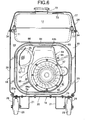
- FIG. 4 is a vertical cross-sectional front view of the engine generator shown in FIG. 1;
- FIG. 5 is a cross-sectional view taken along line 5-5 in FIG. 4;
- FIG. 6 is a magnified cross-sectional view taken along line 6-6 in FIG. 4;
- FIG. 7 is a magnified cross-sectional view taken along line 7-7 in FIG. 4.
- an engine generator includes a soundproofing case 18 housing an engine 11, a fuel tank 12, a generator 13 driven by the engine 11, a battery 14, an air cleaner 15, a carburetor 16 and an exhaust muffler 17 connected to the engine 11.
- the soundproofing case 18 is formed from a substantially rectangular base frame 19, first and second side plates 22, 23 standing on longitudinally opposite ends of the base frame 19, and a cover part 24 covering the base frame 19 between the two side plates 22, 23.
- the base frame 19 is formed from a substantially rectangular base plate 20 and a pair of reinforcing frames 21 fixed to the lower face of the base frame 20.
- the reinforcing frames 21 are fixed at positions spaced in the width direction of the base plate 20 and extending in the longitudinal direction of the base plate 20.
- Each reinforcing frame 21 is formed from substantially U-shaped steel so as to define, between the frame 21 and the lower face of the base plate 20, a space having a rectangular cross section.
- brackets 28 are fixed to the lower face of the base plate 20 at positions adjacent to opposite ends in the longitudinal direction of each of the reinforcing frames 21. Disposed between the brackets 28 and the corresponding reinforcing frame 21 are wheels 29 with their axle shafts being rotatably supported thereby.
- a bent section 20a that is bent upward at a right angle.
- secured to the bent section 20a of the base plate 20 are lower parts of the first and second side plates 22, 23 which are mounted at longitudinally opposite ends of the base plate 20 by means of a plurality of screws 30.
- a handle 31 for carrying the engine generator is fixed to upper parts of the first and second side plates 22, 23.
- the cover part 24 includes a pair of flat parallel side covers 25, 26 and a top cover 27 bridging upper parts of the side covers 25, 26. Opposite ends of each side cover 25, 26 are secured to corresponding sides of the first and second side plates 22, 23 by a plurality of screws 32. A lower part of each side cover 25, 26 is secured to the bent section 20a of the base plate 20 on corresponding sides by a plurality of screws 33.
- the top cover 27 has a substantially inverted U-shaped cross section so as to coincide with the shape of the upper parts of the first and second side plates 22, 23.
- Lower parts, at opposite sides, of the top cover 27 are secured to the upper parts of the side covers 25, 26 by a plurality of screws 34, with the ends of the lower parts of the top cover 27 abutting against the tops of the first and second side plates 22, 23. Furthermore, opposite ends, on opposite sides, of the top cover 27 are secured to the first and second side plates 22, 23, together with the upper parts, at opposite ends of the side covers 25, 26, by the screws 32.
- the engine 11 is a single-cylinder engine having a crankcase 39 supporting a crankshaft 38 extending horizontally in the longitudinal direction of the base frame 19, a cylinder barrel 40 connected to the crankcase 39 and extending upward, and a head cover 41 connected to an upper part of the cylinder barrel 40.
- the crankcase 39 is supported on the base plate 20 of the base frame 19 via a pair of elastic mount members 42. That is, the engine 11 is elastically supported by the base frame 19.
- An engine-side cooling fan 43 is fixedly provided on one end of the crankshaft 38 projecting from the crankcase 39 and is covered with a fan cover 44 fixed to the crankcase 39.
- the fan cover 44 is formed into a shape that opens toward the engine 11 and integrally has a plate-shaped section 44a surrounding the engine-side cooling fan 43 and an air duct section 44b extending upward from the plate-shaped section 44a, a central part of which is provided with an opening 45.
- crankshaft 38 can be engaged and coupled with a recoil starter 46 housed in a plate-shaped recoil starter housing 47, which is coaxially fixed to the plate-shaped section 44a of the fan cover 44.
- a plurality of engine-side inlets 48 are provided on a side wall of the recoil starter housing 47.
- a starter motor 49 is mounted on the outer side of the cylinder barrel 40 in the engine 11 and an actuating force generated by the starter motor 49 can be imparted to the engine 11.
- the generator 13 includes a rotating shaft 50 coaxially connected at one end to the other end of the crankshaft 38.
- a casing 51 of the generator 13 is supported on the base plate 20 of the base frame 19 via a pair of elastic mount members 52. That is, the generator 13 is elastically supported on the base frame 19.
- a generator-side cooling fan 54 is fixed to the one end of the rotating shaft 50 within the casing 51.
- a plurality of air outlets 55 are provided in a lower part of a wall of the casing 51 at one end, in the axial direction of the rotating shaft 50, of the casing 51. That is, the air outlets 55 are provided in a section of the engine generator corresponding to the generator-side cooling fan 54.
- the air outlets 55 are formed so as to eject air toward the inside face of the side cover 26 of the cover part 24.
- the generator 13 is designed so the air that is sucked into the interior of the casing 51 at the other end, in the axial direction, of the rotating shaft 50 is forced to flow to the air outlets 55, thus cooling electrical components within the casing 51.
- an engine-side partition 60 and a generator-side partition 61 Fixedly arranged within the soundproofing case 18 are an engine-side partition 60 and a generator-side partition 61 that define three sections within the soundproofing case 18. More particularly, the three sections are a chamber to be cooled 57, an engine-side air intake chamber 58, and a generator-side air intake chamber 59 on opposite sides of the chamber to be cooled 57.
- the chamber to be cooled 57 houses sections of the engine 11 and the generator 13 that are to be cooled and is formed within the soundproofing case 18 between the engine-side partition 60 and the generator-side partition 61. Moreover, the chamber to be cooled 57 houses the exhaust muffler 17 disposed above the generator 13 so that the opening on the other end of the cover 53 of the engine 11 faces a side face of the exhaust muffler 17.
- the engine-side inlets 48 of the engine 11 are arranged so as to face the engine-side air intake chamber 58.
- the engine-side air intake chamber 58 is formed within the soundproofing case 18 between the engine-side partition 60 and the first side plate 22 forming a part of the soundproofing case 18 and facing the outer side of the engine-side partition 60.
- the generator-side inlets 56 of the generator 13 are arranged so as to face the generator-side air intake chamber 59.
- the generator-side air intake chamber 59 is formed within the soundproofing case 18 between the generator-side partition 61 and the second side plate 23 forming a part of the soundproofing case 18 and facing the outer side of the generator-side partition 61.
- the exhaust muffler 17 is formed into a cylinder with closed opposite ends, is disposed above the generator 13 by effectively utilizing the space above the generator 13, and is supported by a support stay 62 fixed to the casing 51 of the generator 13. Even when the exhaust muffler 17 is of a large size, in order to avoid any increase in the size of the engine generator in the axial direction of the engine 11 and the generator 13, the exhaust muffler 17 is disposed above the generator 13 with a longitudinal axis substantially horizontal in a direction transverse (orthogonal in this embodiment) to the axes of the engine 11 and the generator 13.
- An exhaust pipe 63 extending to the engine 11 is connected to one end of the exhaust muffler 17 facing the side cover 26.
- a partition 64 Disposed horizontally above the exhaust muffler 17 is a partition 64 supported at opposite ends thereof on the engine-side and generator-side partitions 60, 61 so that an exhaust chamber 65 is formed between the partition 64 and the cover part 24 of the soundproofing case 18.
- An inlet 66 is formed between the partition 64 and the soundproofing case 18 on the side of the one end of the exhaust muffler 17, the inlet 66 guiding cooling air that has cooled the engine 11, and the generator 13 into the exhaust chamber 65.
- a pipe 67 communicating at one end with the other end of the exhaust muffler 17 is bent so as to return to the one end of the exhaust muffler 17, and the other end of the pipe 67 is inserted into the exhaust chamber 65 through the inlet 66.
- the exhaust chamber 65 is formed in an upper part of the chamber to be cooled 57 and above the exhaust muffler 17 so as to mix the cooling air that has cooled the engine 11 and the generator 13 with the exhaust gas from the exhaust muffler 17.
- An exhaust vent 68 is provided in the cover part 24, which is an upper part of the soundproofing case 18, on a side wall of the top cover 27 opposite to the inlet 66 so that the mixture of the cooling gas and the exhaust gas from the exhaust chamber 65 is discharged through the exhaust vent 68.
- a rectifying plate 69 Provided in this rectifying plate 69 are a plurality of vertically spaced slit-shaped through holes.
- a plurality of guide plates 70 Provided on the rectifying plate 69 are a plurality of guide plates 70 that guide the flow of gas passing through the through holes so as to project toward the exhaust vent 68 at positions corresponding to the through holes.
- the engine-side air intake chamber 58 houses the fuel tank 12, the air cleaner 15, and the carburetor 16.
- the fuel tank 12 is housed in an upper part of the engine-side air intake chamber 58 so as to be elastically supported by a pair of support frames 71 which are provided between the engine-side partition 60 and the first side plate 22.
- a through hole 74 and a window 75 are provided in the top cover 27.
- a filler tube 72 provided on the top of the fuel tank 12 runs through the through hole 74.
- a fuel gauge 73 provided on the top of the fuel tank 12 faces the window 75.
- the generator-side air intake chamber 59 houses the battery 14 as well as electrical components 76, 77, 78 for operation and control of the engine 11 and the generator 13.
- the electrical component 76 is fixedly supported on the inner face of the second side plate 23.
- the battery 14 is fixedly supported on the base plate 20 of the base frame 19.
- the base plate 20 of the base frame 19 is provided with a pair of engine-side outside air inlets 79 corresponding to the interior of the engine-side air intake chamber 58, and is provided with a pair of generator-side outside air inlets 80 corresponding to the interior of the generator-side air intake chamber 59.
- Each of the outside air inlets 79, 80 is provided in the base plate 20 so as to open within the reinforcing members 21 of the base frame 19. The spaces between the substantially U-shaped reinforcing members 21 and the base plate 20 function as passages for air to flow in from the outside.
- the engine-side partition 60 is formed by providing an endless elastic seal 83 between a case-fixed wall section 81 fixed to the soundproofing case 18 and an engine-fixed wall section 82 fixed to the engine 11 with the gap between the wall section 82 and the outer periphery of the engine 11 being air-tightly sealed.
- the endless elastic seal 83 seals the entire peripheries of the wall sections 81, 82.
- the outer periphery of the case-fixed wall section 81 is formed so as to be in intimate contact with the inside face of the cover part 24 of the soundproofing case 18.
- an opening 84 for the fan cover 44 of the engine 11 to run through is formed into a substantially square shape having rounded corners.
- the elastic seal 83 is attached to the outer periphery of the engine-fixed wall section 82 so as to be in elastically intimate contact with the inner periphery of the opening 84.
- the engine-fixed wall section 82 is fixed to a plurality of, for example, three stays 85 provided on the fan cover 44 of the engine 11. Attached to the inner periphery of the engine-fixed wall section 82 is an elastic seal 86 that is in elastically intimate contact with the outer periphery of the fan cover 44.
- the elastic seal 86 is provided between the engine-side partition 60 and the engine 11.
- the engine-fixed wall section 82 is fixed to the fan cover 44 of the engine 11.
- the plurality of engine-side inlets 48 of the recoil starter housing 47 fixed to the fan cover 44 are provided on the engine-fixed wall section 82 side.
- a first intake pipe 87 is connected at one end to the carburetor 16 housed in the engine-side air intake chamber 58.
- a flange 88 on the other end of the first intake pipe 87 is secured to a flange 89 with the engine-fixed wall section 82 interposed therebetween.
- the flange 89 is integral with one end of a second intake pipe 90, and the other end of the second intake pipe 90 is connected to the engine 11. That is, the first and second intake pipes 87, 90 that provide a connection between the carburetor 16 and the engine 11 are connected so as to communicate with each other with the engine-fixed wall section 82 interposed therebetween, and the carburetor 16 is supported by the engine-fixed wall section 82.
- the generator-side partition 61 is fixed to the soundproofing case 18 so that an outer periphery of the partition 61 is in intimate contact with the inside face of the cover part 24 of the soundproofing case 18.
- an opening 91 is formed into a circular shape so as to correspond to the other end of the casing 51.
- An endless elastic seal 92 in elastically intimate contact with the outer periphery of the other end of the casing 51 is attached to the generator-side partition 61 at the peripheral edge of the opening 91. That is, the elastic seal 92 is provided between the generator-side partition 61 and the generator 13.
- a first ventilation pathway 95 is formed, as shown by arrows in FIGS. 4 and 5, between the pair of engine-side outside air inlets 79, which are provided in the soundproofing case 18 so as to communicate with the engine-side air intake chamber 58, and the exhaust vent 68, which is provided in the soundproofing case 18 so as to communicate with the exhaust chamber 65 in the upper part of the chamber to be cooled 57.
- air that is taken into the engine-side air intake chamber 58 via the engine-side outside air inlets 79 from the outside of the soundproofing case 18 is taken into the fan cover 44 from the engine-side air intake chamber 58 via the engine-side inlets 48 by the engine-side cooling fan 43.
- the air then flows past the sides of the cylinder barrel 40 and the head cover 41 of the engine 11 within the chamber to be cooled 57 and through the exhaust chamber 65 via the inlet 66.
- the air is then discharged via the exhaust vent 68 to the outside of the soundproofing case 18.
- fins 96 provided on the outer faces of the cylinder barrel 40 and the head cover 41 are arranged so as to guide cooling air toward the side of the exhaust muffler 17.
- the side of the exhaust muffler 17 faces the opening of the cover 53 covering the head cover 41 so that the cooling air from the fan cover 44b flows between the head cover 41 and the cover 53.
- the first ventilation pathway 95 is therefore arranged so that, part way along, cooling air is blown directly on the side of the exhaust muffler 17.
- a second ventilation pathway 97 is formed, as shown by the arrow in FIG. 3, between the pair of generator-side outside air inlets 80 which are provided in the soundproofing case 18 so as to communicate with the generator-side air intake chamber 59, and the exhaust vent 68 which is provided in the soundproofing case 18 so as to communicate with the exhaust chamber 65 in the upper part of the chamber to be cooled 57.
- air that is taken into the generator-side air intake chamber 59 via the generator-side outside air inlets 80 from the outside of the soundproofing case 18 is taken into the casing 51 of the generator 13 from the generator-side air intake chamber 59 via the generator-side inlets 56 by the generator-side cooling fan 54.
- the air then passes through the chamber to be cooled 57 via the air outlets 55 in the one end of the casing 51.
- the air then passes through the exhaust chamber 65 via the inlet 66 and is discharged via the exhaust vent 68 to the outside of the soundproofing case 18.
- the air outlets 55 provided in the casing 51 of the generator 13 are formed so as to blow air toward the inside face of the side cover 26 of the cover part 24.
- the second ventilation pathway 97 therefore extends upward along the inside face of the soundproofing case 18 at one end of the exhaust muffler 17 so as to communicate with the exhaust chamber 65.
- a heat insulating material 98 is attached to the engine-side and generator-side partitions 60, 61 on the side of the chamber to be cooled 57.
- a heat insulating material 99 is also attached to the upper face of the partition 64 facing the exhaust chamber 65.
- the interior of the soundproofing case 18 housing the engine 11 and the generator 13 coaxially connected to the engine 11 is divided into three chambers.
- the three chambers are the chamber to be cooled 57, which houses most of the engine 11 and the generator 13, as well as the exhaust muffler 17, and the engine-side and generator-side air intake chambers 58, 59, which are on opposite sides of the chamber to be cooled 57.
- first and second ventilation pathways 95, 97 are formed between the exhaust vent 68 provided in the upper part of the soundproofing case 18 so as to communicate with the chamber to be cooled 57 and the engine-side and generator-side outside air inlets 79, 80 provided in the soundproofing case 18 so as to communicate with the engine-side and generator-side air intake chambers 58, 59.
- air is taken into the engine-side air intake chamber 58 via the engine-side outside air inlets 79 from the outside of the soundproofing case 18, then passes through the chamber to be cooled 57, and is discharged outside the soundproofing case 18 via the exhaust vent 68.
- the second ventilation pathway 97 air is taken into the generator-side air intake chamber 59 via the generator-side outside air inlets 80, then passes through the chamber to be cooled 57, and is discharged outside the soundproofing case 18 via the exhaust vent 68.
- the first and second ventilation pathways 95, 97 are formed so that cooling air flowing into the chamber to be cooled 57 from the engine-side and generator-side air intake chambers 58, 59, which function as low temperature chambers, flows past the engine 11 and the generator 13 disposed in the chamber to be cooled 57, as well as the exhaust muffler 17, which are arranged in the chamber to be cooled 57, and is smoothly discharged to the outside from the exhaust vent 68. Therefore, it becomes possible to cool the engine generator effectively while preventing heat from being retained within the soundproofing case 18. It is also possible to enhance the soundproofing performance by using the two air intake chambers as zones for preventing the leakage of operating noise.
- the engine 11 is elastically supported on the base frame 19 so that the engine-side inlets 48 of the engine 11 face the engine-side air intake chamber 58.
- the generator 13 is elastically supported on the base frame 19 so that the generator-side inlets 56 of the generator 13 face the engine-side air intake chamber 59.
- the engine-side partition 60 disposed between the chamber to be cooled 57 and the engine-side air intake chamber 58, as well as the generator-side partition 61 disposed between the chamber to be cooled 57 and the generator-side air intake chamber 59, are fixedly disposed on the base frame 19, which is a part of the soundproofing case 18.
- the outer peripheries of the engine-side and generator-side partitions 60, 61 are in intimate contact with the inside face of the cover part 24 forming a part of the soundproofing case 18 and covering the engine 11 and the generator 13.
- the exhaust vent 68 is provided in the cover part 24.
- Arranging the cover part 24, which is a part of the soundproofing case 18, so as to cover the engine 11 and the generator 13 can form, within the soundproofing case 18, the chamber to be cooled 57, and the engine-side and generator-side air intake chambers 58, 59, which are defined by the engine-side and generator-side partitions 60, 61.
- Using the cooling air passage of the engine 11 as a passage connecting opposite sides of the engine-side partition 61 and using the cooling air passage of the generator 13 as a passage connecting opposite sides of the generator-side partition 61 allows cooling air to be combined in the chamber to be cooled 57 where the majority of the engine 11 and the generator 13 and the exhaust muffler 17 are housed, and discharged outside via the exhaust vent 68.
- the carrying out of maintenance can thus be made easy, and the cooling air passage can be formed as a simple structure within the soundproofing case 18.
- the soundproofing case 18 includes the first and second side plates 22, 23 that face the outer sides of the engine-side and generator-side partitions 60, 61 with a gap therebetween.
- the engine-side air intake chamber 58 is formed within the soundproofing case 18 between the engine-side partition 60 and the first side plate 21, and the generator-side air intake chamber 59 is formed within the soundproofing case 18 between the generator-side partition 61 and the second side plate 23.
- the engine-side and generator-side outside air inlets 79, 80 are provided in the base frame 19 that forms a part of the soundproofing case 18, the engine-side and generator-side outside air inlets 79, 80 introducing outside air into the engine-side and generator-side air intake chambers 58, 59 respectively, it is possible to introduce the outside air into the two air intake chambers 58, 59 with a simple structure while minimizing leakage of intake noise to the outside, thus maintaining the two air intake chambers 58, 59 at a low temperature.
- the fuel tank 12, the air cleaner 15, and the carburetor 16 are arranged within the engine-side air intake chamber 58, and the battery 14 and the electrical components 76 to 78 are arranged within the generator-side air intake chamber 59. Therefore, housing the components that should avoid high temperatures, such as the fuel tank 12, the air cleaner 15, the carburetor 16, the battery 14, and the electrical components 76 to 78 within the respective air intake chambers 58, 59 so as to correspond to the engine 11 and the generator 13 and maintaining each of the air intake chambers 58, 59 at a low temperature, eliminates the need for a special arrangement of parts and measures for heat shielding.
- disposing the carburetor 16 in the engine-side air intake chamber 58 having a low temperature maintains the air supplied to the engine 11 via the carburetor 16 at a low temperature, thereby maintaining high intake charge efficiency of the engine 11.
- the elastic seals 86, 92 are provided between the engine-side partition 60 and the engine 11 and between the generator-side partition 61 and the generator 13, respectively, and the flow of air from the chamber to be cooled 57 having a high temperature to the air intake chambers 58, 59 on opposite sides thereof having a low temperature can be reliably blocked. Accordingly, leakage of heat from the chamber to be cooled 57 to the air intake chambers 58, 59 on opposite sides thereof is suppressed, and the air intake chambers 58, 59 are imparted with the function of suppressing noise leakage from the soundproofing case 18.
- the exhaust muffler 17 is arranged above the generator 13 in the chamber to be cooled 57 and the exhaust vent 68 is provided above the exhaust muffler 17 in the cover part 24 of the soundproofing case 18, the ventilation effect from the natural convection within the chamber to be cooled 57 is enhanced, thereby decreasing the temperature of the interior of the soundproofing case 18 relatively fast even after the engine generator is stopped. Moreover, the flow of air caused by the natural convection is forced to flow above the sections of the engine 11 and the generator 13 disposed within the chamber to be cooled 57, thus enhancing the cooling effect.
- the engine-side partition 60 is formed by providing the elastic seal 83 between the case-fixed wall section 81 that is attached to the soundproofing case 18 and the engine-fixed wall section 82 that is attached to the engine 11 by air-tightly sealing the gap between the engine-fixed wall section 82 and the engine 11 with the elastic seal 86.
- the first and second intake pipes 87, 90 connecting the carburetor 16 and the engine 11 are supported on the engine-fixed wall section 82 that vibrates together with the engine 11.
- the engine-side inlets 48 are provided in the recoil starter housing 47 that vibrates together with the engine-fixed wall section 82.
- the pipe 67 for guiding exhaust gas from the exhaust muffler 17 is connected to the exhaust chamber 65. That is, the exhaust chamber 65 is formed by partitioning the upper space of the chamber to be cooled 57 with the partition 64.
- the exhaust chamber 65 combines the exhaust gas from the exhaust muffler 17 with the cooling air that has cooled the engine 11, the generator 13, and the exhaust muffler 17 by passing through the first and second ventilation pathways 95, 97, and guiding the combined exhaust gas and the cooling air to the exhaust vent 68.
- the presence of the partition 64 between the exhaust muffler 17 and the exhaust vent 68 effectively reduces the leakage of operating noise generated in the exhaust muffler 17 and lessens the influence of exhaust heat on the engine 11 and the generator 13. Moreover, since the exhaust gas from the exhaust muffler 17 and the cooling air that has cooled the engine 11, the generator 13, and the exhaust muffler 17 are combined in the exhaust chamber 65 and then discharged outside the soundproofing case 18, the exhaust noise is reduced.
- the first ventilation pathway 95 extending to the exhaust chamber 65 while cooling the engine 11 is arranged so that, part way along, cooling air is blown directly onto the side of the exhaust muffler 17.
- the second ventilation pathway 97 extending to the exhaust chamber 65 while cooling the generator 13 is arranged so that, part way along, it passes upward along the inside face of the soundproofing case 18 at said one end of the exhaust muffler 17.
- cooling air directly blowing the cooling air onto the side of the exhaust muffler 17 can effectively cool the exhaust muffler 17. Furthermore, since the cooling air from the generator 13 flows upward along the inside face of the soundproofing case 18 at the one end of the exhaust muffler 17, that is, on the inlet 66 side of the exhaust chamber 65, cooling air, including the cooling air that has cooled the exhaust muffler 17, can be guided smoothly to the exhaust chamber 65.
- An engine generator including a soundproofing case that houses an engine and a generator therein.
- the engine includes an engine-side cooling fan and an engine-side inlet.
- the generator includes a generator-side cooling fan and a generator-side inlet.
- the engine generator further includes an engine-side partition and a generator-side partition fixedly disposed within the soundproofing case to define a chamber to be cooled that houses sections of the engine and the generator that are to be cooled, an engine-side air intake chamber that the engine-side inlet faces, and a generator-side air intake chamber that the generator-side inlet faces.
- the soundproofing case includes a cover part whose inside face is in intimate contact with the outer peripheries of the engine-side and generator-side partitions and has an exhaust vent in a part corresponding to the chamber to be cooled.
Abstract
Description
- The present invention relates to an engine generator. In particular, the present invention relates to an improvement of an engine generator in which an engine and a generator are housed in a soundproofing case. The engine includes a crankshaft, an engine-side cooling fan fixed to the crankshaft, and an engine-side inlet provided at one end, in the axial direction, of the crankshaft for guiding cooling air to the engine-side cooling fan. The generator includes a rotating shaft connected at one end to the other end of the crankshaft, a generator-side cooling fan fixed to the rotating shaft, and a generator-side inlet provided at the other end, in the axial direction, of the rotating shaft for guiding cooling air to the generator-side cooling fan.
- Engine-driven generators are typically used as a power source for work performed outdoors such as, for example, on construction sites. Furthermore, many generators are completely covered with a soundproofing case so as to minimize operating noise in consideration of the operational and surrounding environments when performing work at night in an urban area. In engine generators with such a soundproofing case, the number of intake and exhaust openings is decreased and the size of the intake and exhaust openings is reduced in the pursuit of achieving operational silence. However, since the overall size of the openings is small, adequate consideration to cooling the interior of the soundproofing case must be taken.
- From such a viewpoint, an engine generator disclosed in Japanese Utility Model Registration Publication No. 1-3777 includes, within a soundproofing case, a duct covering an engine cylinder head and an exhaust muffler, wherein cooling air is forcibly driven into the duct by a cooling fan, thereby cooling the engine and the exhaust muffler and eliminating thermal effects on other components of the generator.
- Furthermore, an engine generator disclosed in Japanese Patent Application Laid-open No. 11-62607 has a dual structure in which a duct covering an engine, a generator, and an exhaust muffler is arranged within a soundproofing case, and cooling air is forcibly driven into the duct, thereby cooling a high temperature section and eliminating thermal effects on other components of the generator.
- However, in the arrangement disclosed in Japanese Utility Model Registration Publication No. 1-3777, since outer shells of the engine and the generator are exposed within the soundproofing case, there is a possibility that, depending on the arrangement of internal components, heat released from the outer shells of the engine and the generator might be retained within the soundproofing case. Moreover, in the arrangement disclosed in Japanese Patent Application Laid-open No. 11-62607, the structure for forming a passage for the cooling air is complicated, and during maintenance it is necessary to remove and install the duct in addition to removing and installing the soundproofing case, which is troublesome, requires additional time, and increases overall maintenance costs.
- It is an object of the present invention to overcome the deficiencies of the above-discussed related art. It is also an object of the present invention to provide an engine generator that enables an engine and a generator to be cooled by means of a simple structure and for which maintenance operations are easily carried out.
- In order to accomplish the above-mentioned objects, the engine generator of the present invention includes an engine, a generator, and a soundproofing case housing the engine and the generator. The engine includes a crankshaft, an engine-side cooling fan fixed to the crankshaft, and an engine-side inlet at one end, in the axial direction, of the crankshaft, the engine-side inlet guiding cooling air to the engine-side cooling fan. The generator includes a rotating shaft coaxially connected at one end to the other end of the crankshaft, a generator-side cooling fan fixed to the rotating shaft, and a generator-side inlet at the other end, in the axial direction, of the rotating shaft, the generator-side inlet guiding cooling air to the generator-side cooling fan.
- The engine generator further includes an engine-side partition fixedly disposed within the soundproofing case and defining a chamber to be cooted that houses sections of the engine and the generator that are to be cooled, and an engine-side air intake chamber that the engine-side inlet faces. The engine generator also includes a generator-side partition fixedly disposed within the soundproofing case so as to define the chamber to be cooled and a generator-side air intake chamber that the generator-side inlet faces. The soundproofing case includes a cover part covering the engine and the generator. The outer peripheries of the engine-side and generator-side partitions are in intimate contact with the inside face of the cover part. An exhaust vent is provided in an area of the cover part corresponding to the chamber to be cooled.
- In accordance with the above-described structural arrangement, since the cover part, which is a component of the soundproofing case, is arranged so as to cover the engine and the generator, spaces defined by the engine-side and generator-side partitions are formed within the soundproofing case. A cooling air passage of the engine is used as a passage connecting opposite sides of the engine-side partition. A cooling air passage of the generator can also be used as a passage connecting opposite sides of the generator-side partition. Thus, cooling air is forced to flow so as to be combined in the chamber to be cooled where the sections to be cooled of the engine and the generator are housed, and then discharged to the outside from the exhaust vent, thereby forming the passages for cooling air within the soundproofing case with a simple structure while allowing maintenance to be carried out easily.
- In addition to the above-described structural arrangement, the engine generator can also include an exhaust muffler, an air cleaner, a carburetor, and an electrical component. Additionally, the soundproofing case may include first and second side plates facing the outside faces of the engine-side and generator-side partitions with a gap therebetween. The exhaust muffler and the majority of the engine and the generator are housed in the chamber to be cooled. The air cleaner and the carburetor are housed in the engine-side air intake chamber formed within the soundproofing case between the engine-side partition and the first side plate. The electrical component is housed in the generator-side air intake chamber formed within the soundproofing case between the generator-side partition and the second side plate.
- Accordingly, the soundproofing case is easily divided into the chamber to be cooled having a high temperature, which is in the middle, and air intake chambers having a low temperature on opposite sides of the chamber to be cooled, so that the arrangement of components can be appropriately achieved for the respective chambers to be effectively cooled.
- The engine generator may further include an elastic seal provided between the engine-side partition and the engine, and an elastic seal provided between the generator-side partition and the generator. In accordance with this arrangement, it is possible to reliably block the flow of air from the chamber to be cooled having a high temperature to the air intake chambers having a low temperature on opposite sides of the chamber to be cooled, thus suppressing heat leakage from the chamber to be cooled to the air intake chambers on opposite sides thereof as well as imparting to the air intake chambers the function of suppressing noise leakage.
- The engine generator may also include a base frame, an engine-side outside air inlet, and a generator-side outside air inlet. The base frame forms a part of the soundproofing case, the engine and the generator are disposed on the base frame, the engine-side and generator-side outside air inlets guide outside air to the engine-side and generator-side air intake chambers, respectively, and are provided in the base frame. In accordance with this arrangement, air can be introduced from the outside into the air intake chambers with a simple structure while minimizing leakage of intake noise to the outside.
- The exhaust muffler may also be arranged in the chamber to be cooled above the generator and the exhaust vent provided in the cover part above the exhaust muffler. In accordance with this arrangement, the ventilation effect of natural convection within the chamber to be cooled is enhanced even after the engine generator is stopped. Moreover, the flow of air caused by natural convection is made to flow above the sections of the engine and the generator disposed within the chamber to be cooled, thus enhancing the cooling effect.
- The above-described and other objects, characteristics and advantages of the present invention will become readily apparent from an explanation of a preferred embodiment that will be described in detail below by reference to the attached drawings.
- FIG. 1 is a perspective front view of an engine generator with a top cover removed according to the preferred embodiment of the invention;
- FIG. 2 is a perspective front view of the engine generator shown in FIG. 1 without the cover;
- FIG. 3 is a perspective rear view of the engine generator shown in FIG. 1 without a pair of side plates and the cover;
- FIG. 4 is a vertical cross-sectional front view of the engine generator shown in FIG. 1;
- FIG. 5 is a cross-sectional view taken along line 5-5 in FIG. 4;
- FIG. 6 is a magnified cross-sectional view taken along line 6-6 in FIG. 4; and
- FIG. 7 is a magnified cross-sectional view taken along line 7-7 in FIG. 4.
- Referring to FIGS. 1 to 5, an engine generator includes a
soundproofing case 18 housing anengine 11, afuel tank 12, agenerator 13 driven by theengine 11, abattery 14, anair cleaner 15, acarburetor 16 and anexhaust muffler 17 connected to theengine 11. Thesoundproofing case 18 is formed from a substantiallyrectangular base frame 19, first andsecond side plates base frame 19, and acover part 24 covering thebase frame 19 between the twoside plates - The
base frame 19 is formed from a substantiallyrectangular base plate 20 and a pair of reinforcingframes 21 fixed to the lower face of thebase frame 20. Thereinforcing frames 21 are fixed at positions spaced in the width direction of thebase plate 20 and extending in the longitudinal direction of thebase plate 20. Each reinforcingframe 21 is formed from substantially U-shaped steel so as to define, between theframe 21 and the lower face of thebase plate 20, a space having a rectangular cross section. Moreover,brackets 28 are fixed to the lower face of thebase plate 20 at positions adjacent to opposite ends in the longitudinal direction of each of thereinforcing frames 21. Disposed between thebrackets 28 and the corresponding reinforcingframe 21 arewheels 29 with their axle shafts being rotatably supported thereby. - Provided on the periphery of the
base plate 20 is abent section 20a that is bent upward at a right angle. Secured to thebent section 20a of thebase plate 20 are lower parts of the first andsecond side plates base plate 20 by means of a plurality ofscrews 30. Ahandle 31 for carrying the engine generator is fixed to upper parts of the first andsecond side plates - Referring to FIGS. 6 and 7, the
cover part 24 includes a pair of flat parallel side covers 25, 26 and atop cover 27 bridging upper parts of the side covers 25, 26. Opposite ends of eachside cover second side plates screws 32. A lower part of eachside cover bent section 20a of thebase plate 20 on corresponding sides by a plurality ofscrews 33. Thetop cover 27 has a substantially inverted U-shaped cross section so as to coincide with the shape of the upper parts of the first andsecond side plates top cover 27 are secured to the upper parts of the side covers 25, 26 by a plurality ofscrews 34, with the ends of the lower parts of thetop cover 27 abutting against the tops of the first andsecond side plates top cover 27 are secured to the first andsecond side plates screws 32. - The
engine 11 is a single-cylinder engine having acrankcase 39 supporting acrankshaft 38 extending horizontally in the longitudinal direction of thebase frame 19, acylinder barrel 40 connected to thecrankcase 39 and extending upward, and ahead cover 41 connected to an upper part of thecylinder barrel 40. Thecrankcase 39 is supported on thebase plate 20 of thebase frame 19 via a pair ofelastic mount members 42. That is, theengine 11 is elastically supported by thebase frame 19. - An engine-
side cooling fan 43 is fixedly provided on one end of thecrankshaft 38 projecting from thecrankcase 39 and is covered with afan cover 44 fixed to thecrankcase 39. Thefan cover 44 is formed into a shape that opens toward theengine 11 and integrally has a plate-shapedsection 44a surrounding the engine-side cooling fan 43 and anair duct section 44b extending upward from the plate-shapedsection 44a, a central part of which is provided with anopening 45. - One end of the
crankshaft 38 can be engaged and coupled with arecoil starter 46 housed in a plate-shapedrecoil starter housing 47, which is coaxially fixed to the plate-shapedsection 44a of thefan cover 44. A plurality of engine-side inlets 48 are provided on a side wall of therecoil starter housing 47. - When the engine-
side cooling fan 43 rotates together with thecrankshaft 38 during operation of theengine 11, air that is taken into therecoil starter housing 47 via the engine-side inlets 48 is guided to the interior of the plate-shapedsection 44a of thefan cover 44 via theopening 45. Centrifugal force of the engine-side cooling fan 43 acting on the air within the plate-shapedsection 44a forces the cooling air to flow from the plate-shapedsection 44a to theair duct section 44b, from theair duct section 44b to thecylinder barrel 40 and thehead cover 41 of theengine 11. Mounted on and covering thehead cover 41 of theengine 11 is acover 53 connected to theair duct section 44b of thefan cover 44 at one end and is open at the other end. The cooling air flowing from theair duct section 44b flows between thehead cover 41 and thecover 53. - A
starter motor 49 is mounted on the outer side of thecylinder barrel 40 in theengine 11 and an actuating force generated by thestarter motor 49 can be imparted to theengine 11. - The
generator 13 includes arotating shaft 50 coaxially connected at one end to the other end of thecrankshaft 38. Acasing 51 of thegenerator 13 is supported on thebase plate 20 of thebase frame 19 via a pair ofelastic mount members 52. That is, thegenerator 13 is elastically supported on thebase frame 19. - A generator-
side cooling fan 54 is fixed to the one end of therotating shaft 50 within thecasing 51. A plurality ofair outlets 55 are provided in a lower part of a wall of thecasing 51 at one end, in the axial direction of therotating shaft 50, of thecasing 51. That is, theair outlets 55 are provided in a section of the engine generator corresponding to the generator-side cooling fan 54. Theair outlets 55 are formed so as to eject air toward the inside face of theside cover 26 of thecover part 24. - The
generator 13 is designed so the air that is sucked into the interior of thecasing 51 at the other end, in the axial direction, of therotating shaft 50 is forced to flow to theair outlets 55, thus cooling electrical components within thecasing 51. Provided on the face of thecasing 51 at the other end, in the axial direction, of therotating shaft 50 are a plurality of generator-side inlets 56 through which cooling air is sucked into the interior of thecasing 51 in response to the action of the generator-side cooling fan 54. - Fixedly arranged within the soundproofing
case 18 are an engine-side partition 60 and a generator-side partition 61 that define three sections within the soundproofingcase 18. More particularly, the three sections are a chamber to be cooled 57, an engine-sideair intake chamber 58, and a generator-sideair intake chamber 59 on opposite sides of the chamber to be cooled 57. - The chamber to be cooled 57 houses sections of the
engine 11 and thegenerator 13 that are to be cooled and is formed within the soundproofingcase 18 between the engine-side partition 60 and the generator-side partition 61. Moreover, the chamber to be cooled 57 houses theexhaust muffler 17 disposed above thegenerator 13 so that the opening on the other end of thecover 53 of theengine 11 faces a side face of theexhaust muffler 17. - The engine-
side inlets 48 of theengine 11 are arranged so as to face the engine-sideair intake chamber 58. The engine-sideair intake chamber 58 is formed within the soundproofingcase 18 between the engine-side partition 60 and thefirst side plate 22 forming a part of the soundproofingcase 18 and facing the outer side of the engine-side partition 60. The generator-side inlets 56 of thegenerator 13 are arranged so as to face the generator-sideair intake chamber 59. The generator-sideair intake chamber 59 is formed within the soundproofingcase 18 between the generator-side partition 61 and thesecond side plate 23 forming a part of the soundproofingcase 18 and facing the outer side of the generator-side partition 61. - The
exhaust muffler 17 is formed into a cylinder with closed opposite ends, is disposed above thegenerator 13 by effectively utilizing the space above thegenerator 13, and is supported by asupport stay 62 fixed to thecasing 51 of thegenerator 13. Even when theexhaust muffler 17 is of a large size, in order to avoid any increase in the size of the engine generator in the axial direction of theengine 11 and thegenerator 13, theexhaust muffler 17 is disposed above thegenerator 13 with a longitudinal axis substantially horizontal in a direction transverse (orthogonal in this embodiment) to the axes of theengine 11 and thegenerator 13. - An
exhaust pipe 63 extending to theengine 11 is connected to one end of theexhaust muffler 17 facing theside cover 26. Disposed horizontally above theexhaust muffler 17 is apartition 64 supported at opposite ends thereof on the engine-side and generator-side partitions exhaust chamber 65 is formed between thepartition 64 and thecover part 24 of the soundproofingcase 18. Aninlet 66 is formed between thepartition 64 and thesoundproofing case 18 on the side of the one end of theexhaust muffler 17, theinlet 66 guiding cooling air that has cooled theengine 11, and thegenerator 13 into theexhaust chamber 65. Apipe 67 communicating at one end with the other end of theexhaust muffler 17 is bent so as to return to the one end of theexhaust muffler 17, and the other end of thepipe 67 is inserted into theexhaust chamber 65 through theinlet 66. - That is, the
exhaust chamber 65 is formed in an upper part of the chamber to be cooled 57 and above theexhaust muffler 17 so as to mix the cooling air that has cooled theengine 11 and thegenerator 13 with the exhaust gas from theexhaust muffler 17. Anexhaust vent 68 is provided in thecover part 24, which is an upper part of the soundproofingcase 18, on a side wall of thetop cover 27 opposite to theinlet 66 so that the mixture of the cooling gas and the exhaust gas from theexhaust chamber 65 is discharged through theexhaust vent 68. - A rectifying
plate 69 extending longitudinally between the engine-side partition 60 and the generator-side partition 61 separates theexhaust chamber 65 and theexhaust vent 68. Provided in this rectifyingplate 69 are a plurality of vertically spaced slit-shaped through holes. Provided on the rectifyingplate 69 are a plurality ofguide plates 70 that guide the flow of gas passing through the through holes so as to project toward theexhaust vent 68 at positions corresponding to the through holes. - The engine-side
air intake chamber 58 houses thefuel tank 12, theair cleaner 15, and thecarburetor 16. Thefuel tank 12 is housed in an upper part of the engine-sideair intake chamber 58 so as to be elastically supported by a pair of support frames 71 which are provided between the engine-side partition 60 and thefirst side plate 22. Moreover, provided in thetop cover 27 are a throughhole 74 and awindow 75. Afiller tube 72 provided on the top of thefuel tank 12 runs through the throughhole 74. Afuel gauge 73 provided on the top of thefuel tank 12 faces thewindow 75. - The generator-side
air intake chamber 59 houses thebattery 14 as well aselectrical components engine 11 and thegenerator 13. Theelectrical component 76 is fixedly supported on the inner face of thesecond side plate 23. Thebattery 14 is fixedly supported on thebase plate 20 of thebase frame 19. - In order to introduce air from outside of the soundproofing
case 18 into the engine-side and generator-sideair intake chambers base plate 20 of thebase frame 19 is provided with a pair of engine-side outsideair inlets 79 corresponding to the interior of the engine-sideair intake chamber 58, and is provided with a pair of generator-side outsideair inlets 80 corresponding to the interior of the generator-sideair intake chamber 59. Each of theoutside air inlets base plate 20 so as to open within the reinforcingmembers 21 of thebase frame 19. The spaces between the substantially U-shaped reinforcingmembers 21 and thebase plate 20 function as passages for air to flow in from the outside. - The engine-
side partition 60 is formed by providing an endlesselastic seal 83 between a case-fixedwall section 81 fixed to thesoundproofing case 18 and an engine-fixedwall section 82 fixed to theengine 11 with the gap between thewall section 82 and the outer periphery of theengine 11 being air-tightly sealed. The endlesselastic seal 83 seals the entire peripheries of thewall sections - The outer periphery of the case-fixed
wall section 81, that is, the outer periphery of the engine-side partition 60, is formed so as to be in intimate contact with the inside face of thecover part 24 of the soundproofingcase 18. Provided in the case-fixedwall section 81 is anopening 84 for thefan cover 44 of theengine 11 to run through. Theopening 84 is formed into a substantially square shape having rounded corners. Theelastic seal 83 is attached to the outer periphery of the engine-fixedwall section 82 so as to be in elastically intimate contact with the inner periphery of theopening 84. The engine-fixedwall section 82 is fixed to a plurality of, for example, three stays 85 provided on thefan cover 44 of theengine 11. Attached to the inner periphery of the engine-fixedwall section 82 is anelastic seal 86 that is in elastically intimate contact with the outer periphery of thefan cover 44. - That is, the
elastic seal 86 is provided between the engine-side partition 60 and theengine 11. The engine-fixedwall section 82 is fixed to thefan cover 44 of theengine 11. The plurality of engine-side inlets 48 of therecoil starter housing 47 fixed to thefan cover 44 are provided on the engine-fixedwall section 82 side. - A
first intake pipe 87 is connected at one end to thecarburetor 16 housed in the engine-sideair intake chamber 58. Aflange 88 on the other end of thefirst intake pipe 87 is secured to aflange 89 with the engine-fixedwall section 82 interposed therebetween. Theflange 89 is integral with one end of asecond intake pipe 90, and the other end of thesecond intake pipe 90 is connected to theengine 11. That is, the first andsecond intake pipes carburetor 16 and theengine 11 are connected so as to communicate with each other with the engine-fixedwall section 82 interposed therebetween, and thecarburetor 16 is supported by the engine-fixedwall section 82. - The generator-
side partition 61 is fixed to thesoundproofing case 18 so that an outer periphery of thepartition 61 is in intimate contact with the inside face of thecover part 24 of the soundproofingcase 18. Provided in the generator-side partition 61 is anopening 91 through which the other end of thecasing 51 of thegenerator 13 is arranged to run. Theopening 91 is formed into a circular shape so as to correspond to the other end of thecasing 51. An endlesselastic seal 92 in elastically intimate contact with the outer periphery of the other end of thecasing 51 is attached to the generator-side partition 61 at the peripheral edge of theopening 91. That is, theelastic seal 92 is provided between the generator-side partition 61 and thegenerator 13. - A
first ventilation pathway 95 is formed, as shown by arrows in FIGS. 4 and 5, between the pair of engine-side outsideair inlets 79, which are provided in thesoundproofing case 18 so as to communicate with the engine-sideair intake chamber 58, and theexhaust vent 68, which is provided in thesoundproofing case 18 so as to communicate with theexhaust chamber 65 in the upper part of the chamber to be cooled 57. Thus, air that is taken into the engine-sideair intake chamber 58 via the engine-side outsideair inlets 79 from the outside of the soundproofingcase 18 is taken into thefan cover 44 from the engine-sideair intake chamber 58 via the engine-side inlets 48 by the engine-side cooling fan 43. The air then flows past the sides of thecylinder barrel 40 and thehead cover 41 of theengine 11 within the chamber to be cooled 57 and through theexhaust chamber 65 via theinlet 66. The air is then discharged via theexhaust vent 68 to the outside of the soundproofingcase 18. - Moreover,
fins 96 provided on the outer faces of thecylinder barrel 40 and thehead cover 41 are arranged so as to guide cooling air toward the side of theexhaust muffler 17. The side of theexhaust muffler 17 faces the opening of thecover 53 covering thehead cover 41 so that the cooling air from thefan cover 44b flows between thehead cover 41 and thecover 53. Thefirst ventilation pathway 95 is therefore arranged so that, part way along, cooling air is blown directly on the side of theexhaust muffler 17. - A
second ventilation pathway 97 is formed, as shown by the arrow in FIG. 3, between the pair of generator-side outsideair inlets 80 which are provided in thesoundproofing case 18 so as to communicate with the generator-sideair intake chamber 59, and theexhaust vent 68 which is provided in thesoundproofing case 18 so as to communicate with theexhaust chamber 65 in the upper part of the chamber to be cooled 57. Thus, air that is taken into the generator-sideair intake chamber 59 via the generator-side outsideair inlets 80 from the outside of the soundproofingcase 18 is taken into thecasing 51 of thegenerator 13 from the generator-sideair intake chamber 59 via the generator-side inlets 56 by the generator-side cooling fan 54. The air then passes through the chamber to be cooled 57 via theair outlets 55 in the one end of thecasing 51. The air then passes through theexhaust chamber 65 via theinlet 66 and is discharged via theexhaust vent 68 to the outside of the soundproofingcase 18. - The
air outlets 55 provided in thecasing 51 of thegenerator 13 are formed so as to blow air toward the inside face of theside cover 26 of thecover part 24. Thesecond ventilation pathway 97 therefore extends upward along the inside face of the soundproofingcase 18 at one end of theexhaust muffler 17 so as to communicate with theexhaust chamber 65. - A
heat insulating material 98 is attached to the engine-side and generator-side partitions heat insulating material 99 is also attached to the upper face of thepartition 64 facing theexhaust chamber 65. - The operation of the present invention is explained below.
- The interior of the soundproofing
case 18 housing theengine 11 and thegenerator 13 coaxially connected to theengine 11 is divided into three chambers. The three chambers are the chamber to be cooled 57, which houses most of theengine 11 and thegenerator 13, as well as theexhaust muffler 17, and the engine-side and generator-sideair intake chambers second ventilation pathways exhaust vent 68 provided in the upper part of the soundproofingcase 18 so as to communicate with the chamber to be cooled 57 and the engine-side and generator-side outsideair inlets soundproofing case 18 so as to communicate with the engine-side and generator-sideair intake chambers first ventilation pathway 95, air is taken into the engine-sideair intake chamber 58 via the engine-side outsideair inlets 79 from the outside of the soundproofingcase 18, then passes through the chamber to be cooled 57, and is discharged outside the soundproofingcase 18 via theexhaust vent 68. In thesecond ventilation pathway 97, air is taken into the generator-sideair intake chamber 59 via the generator-side outsideair inlets 80, then passes through the chamber to be cooled 57, and is discharged outside the soundproofingcase 18 via theexhaust vent 68. - That is, sections of the engine generator that have a high temperature are placed together in the chamber to be cooled 57, which is in the middle relative to the engine-side and generator-side
air intake chambers second ventilation pathways air intake chambers engine 11 and thegenerator 13 disposed in the chamber to be cooled 57, as well as theexhaust muffler 17, which are arranged in the chamber to be cooled 57, and is smoothly discharged to the outside from theexhaust vent 68. Therefore, it becomes possible to cool the engine generator effectively while preventing heat from being retained within the soundproofingcase 18. It is also possible to enhance the soundproofing performance by using the two air intake chambers as zones for preventing the leakage of operating noise. - The
engine 11 is elastically supported on thebase frame 19 so that the engine-side inlets 48 of theengine 11 face the engine-sideair intake chamber 58. Thegenerator 13 is elastically supported on thebase frame 19 so that the generator-side inlets 56 of thegenerator 13 face the engine-sideair intake chamber 59. The engine-side partition 60 disposed between the chamber to be cooled 57 and the engine-sideair intake chamber 58, as well as the generator-side partition 61 disposed between the chamber to be cooled 57 and the generator-sideair intake chamber 59, are fixedly disposed on thebase frame 19, which is a part of the soundproofingcase 18. The outer peripheries of the engine-side and generator-side partitions cover part 24 forming a part of the soundproofingcase 18 and covering theengine 11 and thegenerator 13. Theexhaust vent 68 is provided in thecover part 24. - Arranging the
cover part 24, which is a part of the soundproofingcase 18, so as to cover theengine 11 and thegenerator 13 can form, within the soundproofingcase 18, the chamber to be cooled 57, and the engine-side and generator-sideair intake chambers side partitions engine 11 as a passage connecting opposite sides of the engine-side partition 61 and using the cooling air passage of thegenerator 13 as a passage connecting opposite sides of the generator-side partition 61 allows cooling air to be combined in the chamber to be cooled 57 where the majority of theengine 11 and thegenerator 13 and theexhaust muffler 17 are housed, and discharged outside via theexhaust vent 68. The carrying out of maintenance can thus be made easy, and the cooling air passage can be formed as a simple structure within the soundproofingcase 18. - The soundproofing
case 18 includes the first andsecond side plates side partitions air intake chamber 58 is formed within the soundproofingcase 18 between the engine-side partition 60 and thefirst side plate 21, and the generator-sideair intake chamber 59 is formed within the soundproofingcase 18 between the generator-side partition 61 and thesecond side plate 23. Therefore, it is possible to easily divide the interior of the soundproofingcase 18 into the chamber to be cooled 57 having a high temperature and theair intake chambers chambers - Moreover, since the engine-side and generator-side outside
air inlets base frame 19 that forms a part of the soundproofingcase 18, the engine-side and generator-side outsideair inlets air intake chambers air intake chambers air intake chambers - Furthermore, the
fuel tank 12, theair cleaner 15, and thecarburetor 16 are arranged within the engine-sideair intake chamber 58, and thebattery 14 and theelectrical components 76 to 78 are arranged within the generator-sideair intake chamber 59. Therefore, housing the components that should avoid high temperatures, such as thefuel tank 12, theair cleaner 15, thecarburetor 16, thebattery 14, and theelectrical components 76 to 78 within the respectiveair intake chambers engine 11 and thegenerator 13 and maintaining each of theair intake chambers - Moreover, disposing the
carburetor 16 in the engine-sideair intake chamber 58 having a low temperature maintains the air supplied to theengine 11 via thecarburetor 16 at a low temperature, thereby maintaining high intake charge efficiency of theengine 11. - The elastic seals 86, 92 are provided between the engine-
side partition 60 and theengine 11 and between the generator-side partition 61 and thegenerator 13, respectively, and the flow of air from the chamber to be cooled 57 having a high temperature to theair intake chambers air intake chambers air intake chambers case 18. - Furthermore, since the
exhaust muffler 17 is arranged above thegenerator 13 in the chamber to be cooled 57 and theexhaust vent 68 is provided above theexhaust muffler 17 in thecover part 24 of the soundproofingcase 18, the ventilation effect from the natural convection within the chamber to be cooled 57 is enhanced, thereby decreasing the temperature of the interior of the soundproofingcase 18 relatively fast even after the engine generator is stopped. Moreover, the flow of air caused by the natural convection is forced to flow above the sections of theengine 11 and thegenerator 13 disposed within the chamber to be cooled 57, thus enhancing the cooling effect. - The engine-
side partition 60 is formed by providing theelastic seal 83 between the case-fixedwall section 81 that is attached to thesoundproofing case 18 and the engine-fixedwall section 82 that is attached to theengine 11 by air-tightly sealing the gap between the engine-fixedwall section 82 and theengine 11 with theelastic seal 86. Moreover, the first andsecond intake pipes carburetor 16 and theengine 11 are supported on the engine-fixedwall section 82 that vibrates together with theengine 11. The engine-side inlets 48 are provided in therecoil starter housing 47 that vibrates together with the engine-fixedwall section 82. Thus, even when the external shape of theengine 11 is complicated, a large sealing effect can be obtained while simplifying the seal structure between the chamber to be cooled 57 and the engine-sideair intake chamber 58, thereby facilitating assembly of theengine 11 and the engine-side partition 60. - Arranged in the upper part of the chamber to be cooled 57 are sections of the first and
second ventilation pathways case 18 and thepartition 64 positioned above theexhaust muffler 17. Thepipe 67 for guiding exhaust gas from theexhaust muffler 17 is connected to theexhaust chamber 65. That is, theexhaust chamber 65 is formed by partitioning the upper space of the chamber to be cooled 57 with thepartition 64. Theexhaust chamber 65 combines the exhaust gas from theexhaust muffler 17 with the cooling air that has cooled theengine 11, thegenerator 13, and theexhaust muffler 17 by passing through the first andsecond ventilation pathways exhaust vent 68. - The presence of the
partition 64 between theexhaust muffler 17 and theexhaust vent 68 effectively reduces the leakage of operating noise generated in theexhaust muffler 17 and lessens the influence of exhaust heat on theengine 11 and thegenerator 13. Moreover, since the exhaust gas from theexhaust muffler 17 and the cooling air that has cooled theengine 11, thegenerator 13, and theexhaust muffler 17 are combined in theexhaust chamber 65 and then discharged outside the soundproofingcase 18, the exhaust noise is reduced. - The
first ventilation pathway 95 extending to theexhaust chamber 65 while cooling theengine 11 is arranged so that, part way along, cooling air is blown directly onto the side of theexhaust muffler 17. Thesecond ventilation pathway 97 extending to theexhaust chamber 65 while cooling thegenerator 13 is arranged so that, part way along, it passes upward along the inside face of the soundproofingcase 18 at said one end of theexhaust muffler 17. - Thus, directly blowing the cooling air onto the side of the
exhaust muffler 17 can effectively cool theexhaust muffler 17. Furthermore, since the cooling air from thegenerator 13 flows upward along the inside face of the soundproofingcase 18 at the one end of theexhaust muffler 17, that is, on theinlet 66 side of theexhaust chamber 65, cooling air, including the cooling air that has cooled theexhaust muffler 17, can be guided smoothly to theexhaust chamber 65. - Although an embodiment of the present invention is explained in detail above, the present invention can be modified in a variety of ways without departing from the spirit and scope of the present invention described in the attached claims.
An engine generator including a soundproofing case that houses an engine and a generator therein. The engine includes an engine-side cooling fan and an engine-side inlet. The generator includes a generator-side cooling fan and a generator-side inlet. The engine generator further includes an engine-side partition and a generator-side partition fixedly disposed within the soundproofing case to define a chamber to be cooled that houses sections of the engine and the generator that are to be cooled, an engine-side air intake chamber that the engine-side inlet faces, and a generator-side air intake chamber that the generator-side inlet faces. The soundproofing case includes a cover part whose inside face is in intimate contact with the outer peripheries of the engine-side and generator-side partitions and has an exhaust vent in a part corresponding to the chamber to be cooled.
Claims (10)
- An engine generator comprising:wherein the soundproofing case includes a cover part that covers the engine and the generator, outer peripheries of the engine-side and generator-side partitions are in intimate contact with an inside face of the cover part, and the cover part has an exhaust vent disposed in a region corresponding to the chamber to be cooled.an engine including a crankshaft, an engine-side cooling fan fixed to the crankshaft, and an engine-side inlet at one end, in an axial direction, of the crankshaft, wherein the engine-side inlet guides cooling air to the engine-side cooling fan;a generator including a rotating shaft coaxially connected at one end to the other end of the crankshaft, a generator-side cooling fan fixed to the rotating shaft, and a generator-side inlet at the other end, in an axial direction, of the rotating shaft, wherein the generator-side inlet guides cooling air to the generator-side cooling fan;a soundproofing case housing the engine and the generator;an engine-side partition fixedly disposed within the soundproofing case and defining a chamber to be cooled and an engine-side air intake chamber, wherein the chamber to be cooled houses sections of the engine and the generator that are to be cooled and the engine-side air intake chamber faces the engine-side inlet; anda generator-side partition fixedly disposed within the soundproofing case and defining the chamber to be cooled and a generator-side air intake chamber that faces the generator-side inlet,
- The engine generator according to claim 1 further comprising:wherein the soundproofing case includes first and second side plates facing outside faces of the engine-side and generator-side partitions with a gap defined therebetween,an exhaust muffler;an air cleaner;a carburetor; andan electrical component;
wherein the exhaust muffler and a substantial portion of the engine and the generator are housed in the chamber to be cooled,
wherein the air cleaner and the carburetor are housed in the engine-side air intake chamber between the engine-side partition and the first side plate, and
wherein the electrical component is housed in the generator-side air intake chamber between the generator-side partition and the second side plate. - The engine generator according to claim 2 further comprising:an elastic seal provided between the engine-side partition and the engine; andan elastic seal provided between the generator-side partition and the generator.
- The engine generator according to claim 2 further comprising:wherein the base frame forms a part of the soundproofing case,a base frame;an engine-side outside air inlet; anda generator-side outside air inlet;
wherein the engine and the generator are disposed on the base frame, and
wherein the engine-side and generator-side outside air inlets that guide air from the outside to the engine-side and generator-side air intake chambers, respectively, are provided in the base frame. - The engine generator according to claim 2, wherein the exhaust muffler is arranged in the chamber to be cooled above the generator, and
the exhaust vent is provided in the cover part above the exhaust muffler. - The engine generator according to claim 1, wherein the crankshaft and rotating shaft are coaxial.
- The engine generator according to claim 3 further comprising:wherein the base frame forms a part of the soundproofing case,a base frame;an engine-side outside air inlet; anda generator-side outside air inlet;
wherein the engine and the generator are disposed on the base frame, and
wherein the engine-side and generator-side outside air inlets that guide air from the outside to the engine-side and generator-side air intake chambers, respectively, are provided in the base frame. - The engine generator according to claim 3, wherein the exhaust muffler is arranged in the chamber to be cooled above the generator, and
the exhaust vent is provided in the cover part above the exhaust muffler. - The engine generator according to claim 4, wherein the exhaust muffler is arranged in the chamber to be cooled above the generator, and
the exhaust vent is provided in the cover part above the exhaust muffler. - The engine generator according to claim 7, wherein the exhaust muffler is arranged in the chamber to be cooled above the generator, and
the exhaust vent is provided in the cover part above the exhaust muffler.
Applications Claiming Priority (2)
| Application Number | Priority Date | Filing Date | Title |
|---|---|---|---|
| JP2001290822 | 2001-09-25 | ||
| JP2001290822A JP4052823B2 (en) | 2001-09-25 | 2001-09-25 | Engine generator |
Publications (2)
| Publication Number | Publication Date |
|---|---|
| EP1296040A1 true EP1296040A1 (en) | 2003-03-26 |
| EP1296040B1 EP1296040B1 (en) | 2004-03-17 |
Family
ID=19113063
Family Applications (1)
| Application Number | Title | Priority Date | Filing Date |
|---|---|---|---|
| EP02021482A Expired - Fee Related EP1296040B1 (en) | 2001-09-25 | 2002-09-25 | Engine generator |
Country Status (5)
| Country | Link |
|---|---|
| US (1) | US6784560B2 (en) |
| EP (1) | EP1296040B1 (en) |
| JP (1) | JP4052823B2 (en) |
| CN (1) | CN1185408C (en) |
| DE (1) | DE60200266T2 (en) |
Cited By (3)
| Publication number | Priority date | Publication date | Assignee | Title |
|---|---|---|---|---|
| WO2005017347A1 (en) * | 2003-08-06 | 2005-02-24 | Briggs & Stratton Power Products Group, Llc | Method of and system for starting engine-driven power equipment |
| EP2138685A1 (en) * | 2008-06-27 | 2009-12-30 | Honda Motor Co., Ltd. | Engine generator |
| EP2738368A1 (en) * | 2012-11-30 | 2014-06-04 | Kohler Co. | An enclosure guide system for a towable generator |
Families Citing this family (35)
| Publication number | Priority date | Publication date | Assignee | Title |
|---|---|---|---|---|
| CN100549384C (en) * | 2002-07-30 | 2009-10-14 | 雅马哈发动机动力产品株式会社 | Engine generator |
| JP2004060570A (en) * | 2002-07-30 | 2004-02-26 | Yamaha Motor Co Ltd | Engine generator |
| US20050151374A1 (en) * | 2004-01-10 | 2005-07-14 | Ambrose Donald L. | Multi-function integrated portable power and utility apparatus |
| US7745946B2 (en) * | 2004-01-10 | 2010-06-29 | Gary Carter, Sr. | Multifunction integrated portable power and utility apparatus |
| US7449793B2 (en) * | 2004-02-18 | 2008-11-11 | Bluwav Systems, Llc | Portable range extender with autonomous control of starting and stopping operations |
| US7023101B2 (en) * | 2004-03-29 | 2006-04-04 | Wen-Chang Wang | Air cooling generator |
| US7537070B2 (en) * | 2004-06-22 | 2009-05-26 | Bluwav Systems Llc | Autonomous portable range extender |
| US7635932B2 (en) * | 2004-08-18 | 2009-12-22 | Bluwav Systems, Llc | Dynamoelectric machine having heat pipes embedded in stator core |
| US7687945B2 (en) * | 2004-09-25 | 2010-03-30 | Bluwav Systems LLC. | Method and system for cooling a motor or motor enclosure |
| US7389760B2 (en) * | 2006-05-10 | 2008-06-24 | Ford Global Technologies, Llc | Modular engine cover |
| US7492050B2 (en) * | 2006-10-24 | 2009-02-17 | Briggs & Stratton Corporation | Cooling system for a portable generator |
| JP4974155B2 (en) * | 2007-04-02 | 2012-07-11 | ヤマハモーターパワープロダクツ株式会社 | Sound insulation type engine generator |
| JP2008255831A (en) * | 2007-04-02 | 2008-10-23 | Yamaha Motor Powered Products Co Ltd | Soundproof engine generator |
| JP5285310B2 (en) * | 2008-03-14 | 2013-09-11 | 本田技研工業株式会社 | Engine driven generator |
| US8037966B2 (en) * | 2008-06-25 | 2011-10-18 | Caterpillar Inc. | Roof-mounted muffler for system for generating electric power |
| CN101392683A (en) * | 2008-10-16 | 2009-03-25 | 无锡开普动力有限公司 | Fixed DC charging electric generator |
| US8049346B2 (en) * | 2009-08-20 | 2011-11-01 | Timothy Blair Kitch | Reliability and serviceability enhanced engine driven electrical generating system |
| US8899378B2 (en) | 2011-09-13 | 2014-12-02 | Black & Decker Inc. | Compressor intake muffler and filter |
| AU2012216658B2 (en) | 2011-09-13 | 2016-09-15 | Black & Decker Inc | Method of reducing air compressor noise |
| US9404416B2 (en) * | 2012-03-20 | 2016-08-02 | Gino Kennedy | Generator compressor combination power system |
| USD731971S1 (en) * | 2012-12-19 | 2015-06-16 | Kohler Co. | Generator enclosure |
| EP2767675A1 (en) * | 2013-02-15 | 2014-08-20 | Siemens Aktiengesellschaft | Through flow ventilation system for a power generation turbine package |
| US8870150B2 (en) * | 2013-03-18 | 2014-10-28 | Wen Chang Wang | Frame for power machinery |
| JP2014190323A (en) * | 2013-03-28 | 2014-10-06 | Yanmar Co Ltd | Engine |
| EP3017902B1 (en) * | 2014-11-07 | 2017-03-29 | The Esab Group, Inc. | Ruggedized casing for a portable welding system |
| CN104675519B (en) * | 2015-02-15 | 2018-02-13 | 江苏苏美达机电科技有限公司 | Jing Yin air-cooled generator group |
| USD785568S1 (en) | 2015-06-02 | 2017-05-02 | Kohler Co. | Generator enclosure |
| US11111913B2 (en) | 2015-10-07 | 2021-09-07 | Black & Decker Inc. | Oil lubricated compressor |
| US10260409B2 (en) | 2016-02-12 | 2019-04-16 | Evolve Holdings, Inc. | Scalable electrical power generator set and related methods |
| CN105927361A (en) * | 2016-07-06 | 2016-09-07 | 重庆大江动力设备制造有限公司 | Pushing type diesel generator set |
| CN106451917B (en) * | 2016-11-30 | 2023-04-21 | 北京三一智能电机有限公司 | Generator and wind power plant |
| US10927732B2 (en) | 2018-03-28 | 2021-02-23 | Cummins Power Generation Ip, Inc. | Low noise enclosure |
| CN112832905B (en) * | 2021-01-07 | 2022-04-01 | 浙江耀锋动力科技有限公司 | Power generator set |
| CN112910178B (en) * | 2021-03-01 | 2022-08-19 | 山东中喆德元智能装备有限公司 | Three-phase permanent magnet synchronous generator with axial-flow type heat dissipation wind wheel |
| CN113241898B (en) * | 2021-07-09 | 2021-09-10 | 山东赛马力动力科技有限公司 | Cooling device for generator set |
Citations (4)
| Publication number | Priority date | Publication date | Assignee | Title |
|---|---|---|---|---|
| US4608946A (en) * | 1983-05-11 | 1986-09-02 | Honda Giken Kogyo Kabushiki Kaisha | Portable engine-generator set |
| JPH0216333A (en) * | 1988-06-30 | 1990-01-19 | Suzuki Motor Co Ltd | Power generator with sound insulation type engine |
| US5624589A (en) * | 1995-09-11 | 1997-04-29 | Illinois Tool Works Inc. | Segregated cooling air flow for engine driven welder |
| EP0893587A2 (en) * | 1997-07-24 | 1999-01-27 | Honda Giken Kogyo Kabushiki Kaisha | Engine-operated generator |
Family Cites Families (11)
| Publication number | Priority date | Publication date | Assignee | Title |
|---|---|---|---|---|
| JPH0128270Y2 (en) * | 1984-10-09 | 1989-08-29 | ||
| US4702201A (en) * | 1985-10-04 | 1987-10-27 | Honda Giken Kogyo Kabushiki Kaisha | Soundproof type engine working machine |
| US4827147A (en) * | 1986-11-12 | 1989-05-02 | Honda Giken Kogyo Kabushiki Kaisha | Engine-powered portable working apparatus |
| JPS643777A (en) | 1987-06-26 | 1989-01-09 | Nec Corp | Generating system for design component list |
| US5297517A (en) * | 1991-08-19 | 1994-03-29 | Caterpillar Inc. | Noise suppression enclosure for an engine |
| JP2567725Y2 (en) * | 1993-10-19 | 1998-04-02 | デンヨー株式会社 | Low noise structure of soundproof water-cooled engine generator |
| JPH1136886A (en) * | 1997-07-16 | 1999-02-09 | Calsonic Corp | Soundproof structure of working machine |
| JP3815703B2 (en) * | 1997-07-24 | 2006-08-30 | 本田技研工業株式会社 | Engine generator |
| JP3800374B2 (en) | 1997-08-07 | 2006-07-26 | 本田技研工業株式会社 | Engine generator |
| JP3569890B2 (en) * | 2000-06-22 | 2004-09-29 | デンヨー株式会社 | Soundproof engine driven work machine |
| JP3934896B2 (en) * | 2001-09-25 | 2007-06-20 | 本田技研工業株式会社 | Engine generator |
-
2001
- 2001-09-25 JP JP2001290822A patent/JP4052823B2/en not_active Expired - Fee Related
-
2002
- 2002-09-23 US US10/252,122 patent/US6784560B2/en not_active Expired - Fee Related
- 2002-09-25 CN CNB021434336A patent/CN1185408C/en not_active Expired - Fee Related
- 2002-09-25 EP EP02021482A patent/EP1296040B1/en not_active Expired - Fee Related
- 2002-09-25 DE DE60200266T patent/DE60200266T2/en not_active Expired - Lifetime
Patent Citations (4)
| Publication number | Priority date | Publication date | Assignee | Title |
|---|---|---|---|---|
| US4608946A (en) * | 1983-05-11 | 1986-09-02 | Honda Giken Kogyo Kabushiki Kaisha | Portable engine-generator set |
| JPH0216333A (en) * | 1988-06-30 | 1990-01-19 | Suzuki Motor Co Ltd | Power generator with sound insulation type engine |
| US5624589A (en) * | 1995-09-11 | 1997-04-29 | Illinois Tool Works Inc. | Segregated cooling air flow for engine driven welder |
| EP0893587A2 (en) * | 1997-07-24 | 1999-01-27 | Honda Giken Kogyo Kabushiki Kaisha | Engine-operated generator |
Non-Patent Citations (1)
| Title |
|---|
| PATENT ABSTRACTS OF JAPAN vol. 014, no. 155 (M - 0954) 26 March 1990 (1990-03-26) * |
Cited By (6)
| Publication number | Priority date | Publication date | Assignee | Title |
|---|---|---|---|---|
| WO2005017347A1 (en) * | 2003-08-06 | 2005-02-24 | Briggs & Stratton Power Products Group, Llc | Method of and system for starting engine-driven power equipment |
| US7148580B2 (en) | 2003-08-06 | 2006-12-12 | Briggs And Stratton Corporation | Method of and system for starting engine-driven power equipment |
| EP2138685A1 (en) * | 2008-06-27 | 2009-12-30 | Honda Motor Co., Ltd. | Engine generator |
| US8178985B2 (en) | 2008-06-27 | 2012-05-15 | Honda Motor Co., Ltd. | Engine generator |
| EP2738368A1 (en) * | 2012-11-30 | 2014-06-04 | Kohler Co. | An enclosure guide system for a towable generator |
| US8960708B2 (en) | 2012-11-30 | 2015-02-24 | Kohler Co. | Enclosure guide system for a towable generator |
Also Published As
| Publication number | Publication date |
|---|---|
| US20030071465A1 (en) | 2003-04-17 |
| CN1410664A (en) | 2003-04-16 |
| EP1296040B1 (en) | 2004-03-17 |
| JP2003097283A (en) | 2003-04-03 |
| DE60200266D1 (en) | 2004-04-22 |
| US6784560B2 (en) | 2004-08-31 |
| JP4052823B2 (en) | 2008-02-27 |
| DE60200266T2 (en) | 2004-08-05 |
| CN1185408C (en) | 2005-01-19 |
Similar Documents
| Publication | Publication Date | Title |
|---|---|---|
| EP1296040B1 (en) | Engine generator | |
| US6753620B2 (en) | Engine generator | |
| US10186931B2 (en) | Electrical generator heat management system | |
| US6095099A (en) | Engine operated working machine | |
| CA2538275C (en) | Engine-driven working machine | |
| JP2008088852A (en) | Package type compressor | |
| JP3728144B2 (en) | Soundproof engine driven work machine | |
| JP3934897B2 (en) | Engine generator | |
| JP4700571B2 (en) | Engine generator | |
| JP3934898B2 (en) | Engine generator | |
| JP2893437B2 (en) | Method and apparatus for assembling soundproof engine driven generator | |
| JP2545597B2 (en) | Soundproof engine work machine | |
| JPS643777Y2 (en) | ||
| JP3859289B2 (en) | Soundproof engine working machine | |
| JPH0133785Y2 (en) | ||
| JP2536228Y2 (en) | Soundproof engine working machine | |
| JP2784986B2 (en) | Soundproof engine | |
| JP3728043B2 (en) | Outdoor unit of engine-driven heat pump device | |
| JP2003020956A (en) | Sound insulated power generating device | |
| JP2003120310A (en) | Engine generator | |
| JP2003020954A (en) | Sound insulated power generating device | |
| JPS6212349A (en) | Cooling system of engine generator | |
| CA2918574A1 (en) | Electrical generator heat management system |
Legal Events
| Date | Code | Title | Description |
|---|---|---|---|
| PUAI | Public reference made under article 153(3) epc to a published international application that has entered the european phase |
Free format text: ORIGINAL CODE: 0009012 |
|
| AK | Designated contracting states |
Kind code of ref document: A1 Designated state(s): AT BE BG CH CY CZ DE DK EE ES FI FR GB GR IE IT LI LU MC NL PT SE SK TR |
|
| AX | Request for extension of the european patent |
Extension state: AL LT LV MK RO SI |
|
| 17P | Request for examination filed |
Effective date: 20030318 |
|
| GRAP | Despatch of communication of intention to grant a patent |
Free format text: ORIGINAL CODE: EPIDOSNIGR1 |
|
| GRAS | Grant fee paid |
Free format text: ORIGINAL CODE: EPIDOSNIGR3 |
|
| AKX | Designation fees paid |
Designated state(s): DE FR GB IT |
|
| GRAA | (expected) grant |
Free format text: ORIGINAL CODE: 0009210 |
|
| AK | Designated contracting states |
Kind code of ref document: B1 Designated state(s): DE FR GB IT |
|
| REG | Reference to a national code |
Ref country code: GB Ref legal event code: FG4D |
|
| REG | Reference to a national code |
Ref country code: IE Ref legal event code: FG4D |
|
| REF | Corresponds to: |
Ref document number: 60200266 Country of ref document: DE Date of ref document: 20040422 Kind code of ref document: P |
|
| ET | Fr: translation filed | ||
| PLBE | No opposition filed within time limit |
Free format text: ORIGINAL CODE: 0009261 |
|
| STAA | Information on the status of an ep patent application or granted ep patent |
Free format text: STATUS: NO OPPOSITION FILED WITHIN TIME LIMIT |
|
| 26N | No opposition filed |
Effective date: 20041220 |
|
| REG | Reference to a national code |
Ref country code: IE Ref legal event code: MM4A |
|
| PGFP | Annual fee paid to national office [announced via postgrant information from national office to epo] |
Ref country code: DE Payment date: 20140917 Year of fee payment: 13 |
|
| PGFP | Annual fee paid to national office [announced via postgrant information from national office to epo] |
Ref country code: GB Payment date: 20140924 Year of fee payment: 13 |
|
| PGFP | Annual fee paid to national office [announced via postgrant information from national office to epo] |
Ref country code: IT Payment date: 20140917 Year of fee payment: 13 |
|
| PGFP | Annual fee paid to national office [announced via postgrant information from national office to epo] |
Ref country code: FR Payment date: 20140906 Year of fee payment: 13 |
|
| REG | Reference to a national code |
Ref country code: DE Ref legal event code: R119 Ref document number: 60200266 Country of ref document: DE |
|
| PG25 | Lapsed in a contracting state [announced via postgrant information from national office to epo] |
Ref country code: IT Free format text: LAPSE BECAUSE OF NON-PAYMENT OF DUE FEES Effective date: 20150925 |
|
| GBPC | Gb: european patent ceased through non-payment of renewal fee |
Effective date: 20150925 |
|
| REG | Reference to a national code |
Ref country code: FR Ref legal event code: ST Effective date: 20160531 |
|
| PG25 | Lapsed in a contracting state [announced via postgrant information from national office to epo] |
Ref country code: DE Free format text: LAPSE BECAUSE OF NON-PAYMENT OF DUE FEES Effective date: 20160401 Ref country code: GB Free format text: LAPSE BECAUSE OF NON-PAYMENT OF DUE FEES Effective date: 20150925 |
|
| PG25 | Lapsed in a contracting state [announced via postgrant information from national office to epo] |
Ref country code: FR Free format text: LAPSE BECAUSE OF NON-PAYMENT OF DUE FEES Effective date: 20150930 |