EP1296027A2 - Abgasschalldämpfer - Google Patents
Abgasschalldämpfer Download PDFInfo
- Publication number
- EP1296027A2 EP1296027A2 EP02015917A EP02015917A EP1296027A2 EP 1296027 A2 EP1296027 A2 EP 1296027A2 EP 02015917 A EP02015917 A EP 02015917A EP 02015917 A EP02015917 A EP 02015917A EP 1296027 A2 EP1296027 A2 EP 1296027A2
- Authority
- EP
- European Patent Office
- Prior art keywords
- section
- inlet
- flap
- gas
- opening
- Prior art date
- Legal status (The legal status is an assumption and is not a legal conclusion. Google has not performed a legal analysis and makes no representation as to the accuracy of the status listed.)
- Withdrawn
Links
Images

Classifications
-
- F—MECHANICAL ENGINEERING; LIGHTING; HEATING; WEAPONS; BLASTING
- F01—MACHINES OR ENGINES IN GENERAL; ENGINE PLANTS IN GENERAL; STEAM ENGINES
- F01N—GAS-FLOW SILENCERS OR EXHAUST APPARATUS FOR MACHINES OR ENGINES IN GENERAL; GAS-FLOW SILENCERS OR EXHAUST APPARATUS FOR INTERNAL-COMBUSTION ENGINES
- F01N13/00—Exhaust or silencing apparatus characterised by constructional features
- F01N13/16—Selection of particular materials
-
- F—MECHANICAL ENGINEERING; LIGHTING; HEATING; WEAPONS; BLASTING
- F01—MACHINES OR ENGINES IN GENERAL; ENGINE PLANTS IN GENERAL; STEAM ENGINES
- F01N—GAS-FLOW SILENCERS OR EXHAUST APPARATUS FOR MACHINES OR ENGINES IN GENERAL; GAS-FLOW SILENCERS OR EXHAUST APPARATUS FOR INTERNAL-COMBUSTION ENGINES
- F01N1/00—Silencing apparatus characterised by method of silencing
- F01N1/16—Silencing apparatus characterised by method of silencing by using movable parts
- F01N1/165—Silencing apparatus characterised by method of silencing by using movable parts for adjusting flow area
-
- F—MECHANICAL ENGINEERING; LIGHTING; HEATING; WEAPONS; BLASTING
- F01—MACHINES OR ENGINES IN GENERAL; ENGINE PLANTS IN GENERAL; STEAM ENGINES
- F01N—GAS-FLOW SILENCERS OR EXHAUST APPARATUS FOR MACHINES OR ENGINES IN GENERAL; GAS-FLOW SILENCERS OR EXHAUST APPARATUS FOR INTERNAL-COMBUSTION ENGINES
- F01N13/00—Exhaust or silencing apparatus characterised by constructional features
- F01N13/18—Construction facilitating manufacture, assembly, or disassembly
- F01N13/1888—Construction facilitating manufacture, assembly, or disassembly the housing of the assembly consisting of two or more parts, e.g. two half-shells
-
- F—MECHANICAL ENGINEERING; LIGHTING; HEATING; WEAPONS; BLASTING
- F01—MACHINES OR ENGINES IN GENERAL; ENGINE PLANTS IN GENERAL; STEAM ENGINES
- F01N—GAS-FLOW SILENCERS OR EXHAUST APPARATUS FOR MACHINES OR ENGINES IN GENERAL; GAS-FLOW SILENCERS OR EXHAUST APPARATUS FOR INTERNAL-COMBUSTION ENGINES
- F01N1/00—Silencing apparatus characterised by method of silencing
- F01N1/02—Silencing apparatus characterised by method of silencing by using resonance
-
- F—MECHANICAL ENGINEERING; LIGHTING; HEATING; WEAPONS; BLASTING
- F01—MACHINES OR ENGINES IN GENERAL; ENGINE PLANTS IN GENERAL; STEAM ENGINES
- F01N—GAS-FLOW SILENCERS OR EXHAUST APPARATUS FOR MACHINES OR ENGINES IN GENERAL; GAS-FLOW SILENCERS OR EXHAUST APPARATUS FOR INTERNAL-COMBUSTION ENGINES
- F01N13/00—Exhaust or silencing apparatus characterised by constructional features
- F01N13/18—Construction facilitating manufacture, assembly, or disassembly
-
- F—MECHANICAL ENGINEERING; LIGHTING; HEATING; WEAPONS; BLASTING
- F01—MACHINES OR ENGINES IN GENERAL; ENGINE PLANTS IN GENERAL; STEAM ENGINES
- F01N—GAS-FLOW SILENCERS OR EXHAUST APPARATUS FOR MACHINES OR ENGINES IN GENERAL; GAS-FLOW SILENCERS OR EXHAUST APPARATUS FOR INTERNAL-COMBUSTION ENGINES
- F01N2260/00—Exhaust treating devices having provisions not otherwise provided for
- F01N2260/14—Exhaust treating devices having provisions not otherwise provided for for modifying or adapting flow area or back-pressure
-
- F—MECHANICAL ENGINEERING; LIGHTING; HEATING; WEAPONS; BLASTING
- F01—MACHINES OR ENGINES IN GENERAL; ENGINE PLANTS IN GENERAL; STEAM ENGINES
- F01N—GAS-FLOW SILENCERS OR EXHAUST APPARATUS FOR MACHINES OR ENGINES IN GENERAL; GAS-FLOW SILENCERS OR EXHAUST APPARATUS FOR INTERNAL-COMBUSTION ENGINES
- F01N2450/00—Methods or apparatus for fitting, inserting or repairing different elements
- F01N2450/22—Methods or apparatus for fitting, inserting or repairing different elements by welding or brazing
-
- F—MECHANICAL ENGINEERING; LIGHTING; HEATING; WEAPONS; BLASTING
- F01—MACHINES OR ENGINES IN GENERAL; ENGINE PLANTS IN GENERAL; STEAM ENGINES
- F01N—GAS-FLOW SILENCERS OR EXHAUST APPARATUS FOR MACHINES OR ENGINES IN GENERAL; GAS-FLOW SILENCERS OR EXHAUST APPARATUS FOR INTERNAL-COMBUSTION ENGINES
- F01N2470/00—Structure or shape of exhaust gas passages, pipes or tubes
- F01N2470/02—Tubes being perforated
-
- F—MECHANICAL ENGINEERING; LIGHTING; HEATING; WEAPONS; BLASTING
- F01—MACHINES OR ENGINES IN GENERAL; ENGINE PLANTS IN GENERAL; STEAM ENGINES
- F01N—GAS-FLOW SILENCERS OR EXHAUST APPARATUS FOR MACHINES OR ENGINES IN GENERAL; GAS-FLOW SILENCERS OR EXHAUST APPARATUS FOR INTERNAL-COMBUSTION ENGINES
- F01N2470/00—Structure or shape of exhaust gas passages, pipes or tubes
- F01N2470/18—Structure or shape of exhaust gas passages, pipes or tubes the axis of inlet or outlet tubes being other than the longitudinal axis of apparatus
-
- F—MECHANICAL ENGINEERING; LIGHTING; HEATING; WEAPONS; BLASTING
- F01—MACHINES OR ENGINES IN GENERAL; ENGINE PLANTS IN GENERAL; STEAM ENGINES
- F01N—GAS-FLOW SILENCERS OR EXHAUST APPARATUS FOR MACHINES OR ENGINES IN GENERAL; GAS-FLOW SILENCERS OR EXHAUST APPARATUS FOR INTERNAL-COMBUSTION ENGINES
- F01N2510/00—Surface coverings
-
- F—MECHANICAL ENGINEERING; LIGHTING; HEATING; WEAPONS; BLASTING
- F01—MACHINES OR ENGINES IN GENERAL; ENGINE PLANTS IN GENERAL; STEAM ENGINES
- F01N—GAS-FLOW SILENCERS OR EXHAUST APPARATUS FOR MACHINES OR ENGINES IN GENERAL; GAS-FLOW SILENCERS OR EXHAUST APPARATUS FOR INTERNAL-COMBUSTION ENGINES
- F01N2530/00—Selection of materials for tubes, chambers or housings
- F01N2530/02—Corrosion resistive metals
- F01N2530/04—Steel alloys, e.g. stainless steel
Definitions
- the present invention relates to an exhaust silencer, especially for internal combustion engines, with the features of Preamble of claim 1.
- Exhaust silencers of this type are used in particular to on the one hand with low exhaust gas flow rates To dampen noise relatively strongly and on the other hand an excessive back pressure rise with larger exhaust gas throughputs and thus a loss of performance of the respective Avoid internal combustion engine.
- an exhaust silencer is the beginning known type of a housing with a gas supply line and has a gas discharge.
- a valve arrangement for changing the flow cross section a flow path between a supply outlet and a derivative entry is provided.
- This Valve arrangement comprises an actuating element which in Area of the supply line outlet is arranged and via a common shaft is connected to a closure element.
- This closure element controls the flow cross section an additional tube, the two chambers formed in the housing connects with each other.
- the actuator is with spring means biased into a starting position in which the Closure element the flow cross section of the additional tube closes.
- the Actuator is mounted so that it is dependent the exhaust gas volume flow in the gas supply line more or less pivoted, whereby the closure element the flow cross section of the additional tube opens more or less. at more or less open additional pipe is between the supply outlet and a second entry Flow path with a second throttle resistance more or less effective.
- a such valve arrangement is relatively expensive because of the actuating element and closure element independently of each other relative to the respective lines or pipes must be positioned and stored.
- DE 195 03 322 A1 describes a further exhaust silencer known of a housing with a gas supply line and a Has gas discharge.
- the gas supply line is a valve arrangement assigned depending on at least one Parameters the entry cross-section for that in the housing incoming exhaust gas changed.
- the valve arrangement has a valve disc driven by an overpressure can on in a starting position by means of a Helical compression spring axially an outlet end of the gas supply line closes.
- the overpressure can is via a pressure line communicating with the gas supply line, so that the Valve disc depending on the exhaust gas back pressure, i.e. the in the incoming exhaust gas pressure, more or less from the outlet end of the gas supply line.
- the well-known exhaust silencer has a relatively complex structure, because the pressure can is outside the housing of the exhaust silencer is arranged so that a piston rod for actuation of the valve disc penetrate the housing in a sealed manner got to. Furthermore, during assembly and manufacture of the known exhaust silencer relatively narrow tolerances are observed to ensure proper functioning to be able to.
- Another exhaust muffler is known from DE 197 29 666 A1 is known in which the valve assembly through a corrugated tube has driven valve plate.
- a fixed end to the Corrugated tube is in a recess in the housing of the exhaust silencer used, the inside of the corrugated tube through an opening formed in the muffler housing communicates with the atmosphere.
- the Valve disc with spring means in the closing direction against that Outlet end of the gas supply line biased.
- Dependent on of the exhaust gas pressure prevailing in the housing becomes the valve disc axially adjusted so that the inlet cross section for the to change exhaust gas entering the housing.
- the present invention addresses the problem for an exhaust silencer of the type mentioned another embodiment with a relatively easy to implement Specify the structure.
- the invention is based on the general idea of one Flap both for controlling line entry and also used to operate the flap itself. Reached this is relative by a clever arrangement of the flap to an outlet opening of a gas supply line, e.g. Inlet outlet, and to an inlet opening Gas discharge line, e.g. Derivative entry, the Fold an actuating section cooperating with the outlet opening and one cooperating with the entrance opening Has control section.
- the operating section is e.g.
- the actuating section of the flap thus acts with the outlet opening together that in a starting position the Flap has a minimal exit cross section that is expediently greater than zero.
- the outlet opening through the inlet outlet is expedient the gas line.
- the entrance opening through the discharge of the gas discharge be educated.
- the actuating section concave towards the outlet opening in particular be designed as a hemisphere shell.
- This construction enables a pulse reversal of the incoming gas flow at the actuating section the flap, causing the energy of the Gas flow particularly effective for actuating the flap can be exploited.
- control section the flap can be designed as a lid in the Starting position of the flap on a front edge of the Inlet opening lies flush. Accordingly, the Control section or the flap outside of the to be controlled Arranged cross-section, whereby the storage the flap simplified.
- a bypass path bypassing the cover can be provided, which has a minimum flow cross-section for the gas outlet guaranteed from the housing.
- control section have at least one opening that has the minimum entry cross-section forms or form. Such an embodiment is particularly inexpensive to implement.
- the lid is only useful with a single central one Opening equipped with regard to their flow cross-section and especially regarding their Throttle effect can be dimensioned relatively precisely.
- this can be central Opening be equipped with an inlet funnel, which in the starting position of the flap protrudes into the inlet opening.
- a Swivel axis around which the flap is pivotally mounted is closer to the inlet opening than to the outlet opening be arranged.
- the operating section on the flap has a larger lever arm on as the control section.
- an actuator can also be provided, which engages the flap and these parameters are actively adjusted depending.
- this embodiment can be in the damping characteristics regardless of the gas volume flow of the exhaust silencer intervened become. Parameters, depending on which the actuator operated the flap, for example, the exhaust gas pressure in the incoming exhaust gas (exhaust gas back pressure), the exhaust gas temperature, the engine speed, the engine load, the volume and the Be the sound of the alliance noise.
- the flap forcibly via the actuator to position in their starting position, for example minimal flow cross-sections in city traffic between entry and exit.
- the valve arrangement designed with regard to a certain damping characteristic By dimensioning the preload force of the spring means as well as the mass of the flap, the valve arrangement designed with regard to a certain damping characteristic become. This characteristic can correspond to one Further training can be adapted even better to the requirement if the valve arrangement has several such flaps, arranged in series or parallel in the housing and tuned differently acoustically are.
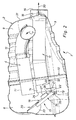
- an inventive one Exhaust silencer 1 on a housing 2 which is usually is made of multiple shells and here a lower shell 3 and an upper shell 31.
- Fig. 1 is only the lower shell 3 of the housing 2 is shown.
- the housing 2 includes a gas supply line 4, one formed on the housing 2 Inlet connector 5 forms a feed inlet 6, by the incoming exhaust gas according to an arrow 7 in the gas supply line 4 enters.
- the housing 2 two chambers, namely a deflection chamber 8 and a resonator chamber 9, formed by a partition 10 from each other are separated gas-tight.
- the inlet nozzle 5 is arranged on the housing 2 so that the gas supply line 4 first runs within the deflection chamber 8, then the Partition 10 penetrates tightly, then within Resonator chamber 9 deflected with an arc of approximately 180 ° is then again penetrated through the partition 10 in a sealed manner, to finally in the deflection chamber 8 with a supply outlet 11 to flow.
- the gas feed line is in the resonator chamber 9 4 porous in an arcuate section 12 gas permeable, trained. Through this porous section 12 can sound that is transported along the gas supply line 4 will emerge into the resonator chamber 9, whereby a sets the desired damping effect. It is useful Resonator chamber 9 filled with a suitable insulation.
- the housing 2 also includes a gas discharge line 13, which in the deflection chamber 8 begins with a discharge inlet 14, penetrates the partition 10 gas-tight, within the resonator chamber 9 runs and with a discharge outlet 15 in an outlet nozzle 16 ends, which is formed in the housing 2 is.
- An arrow 30 symbolizes this from the housing 2 escaping exhaust gas.
- a valve arrangement 17 is also in the deflection chamber 8 arranged to control the flow cross section of a Flow path between the inlet outlet 11 and the Derivation entry 14 is used.
- the valve assembly 17 controlled openings, so here the Inlet outlet 11 and outlet inlet 14, in the housing 2 or arranged on the partition 10 side by side.
- the valve arrangement 17 has a flap 18 which is around a Swivel axis 19 is pivotally mounted. Warehousing the flap 18 is carried out on an annular sleeve 20, on an end section protruding into the deflection chamber 8 32 of the gas discharge line 13 is plugged in and thus is firmly connected. For example, the sleeve 20 with the Gas discharge line 13 soldered or welded.
- the sleeve 20 forms the entry end the gas discharge line 13, so that the discharge inlet 14 thus formed on the sleeve 20 or by the sleeve 20 is.
- bearing arms on the sleeve 21 formed which carry a shaft 22 which is coaxial runs to the pivot axis 19. On this shaft 22 is then the flap 18 is stored.
- a wave 22 can on the bearing arms 21 or on the flap 18 corresponding Bearing pin to be formed in corresponding Bolt receptacles in the flap 18 or in the bearing arms 21 engage, these bearing bolts coaxial to the pivot axis 19 run and thus realize the storage of the flap 18.
- the flap 18 has a distance from the pivot axis 19 Actuating section 23, which with the supply outlet 11 cooperates and here concave towards the supply outlet 11 is trained.
- the operating section 23 is corresponding the preferred embodiment shown here as Shaped hemisphere.
- the flap 18 has near the Pivot axis 19 has a control section 24 which with the Derivation entry 14 cooperates and in the shown here Embodiment is designed as a lid in a 1 shown starting position of the flap 18 on a 2 shows the end edge 25 of the discharge inlet that can be seen in FIG. 2 14 rests flush.
- the valve arrangement 17 also has spring means 26, which are formed by a leg spring, these Leg spring is plugged onto the shaft 22 and itself at one end on the flap 18 and at the other end on the sleeve 20 supported.
- the spring means 26 clamp the flap 18 in the in Fig. 1 shown starting position. In this starting position the actuating section 23 covers the supply outlet 11 more or less completely. Is expedient the actuating section 23 in the starting position the flap 18 so far from the supply outlet 11, that between this supply outlet 11 and the actuating section 23 forms an annular gap that has a minimal Outlet cross section for this inlet outlet 11 guaranteed. In this way it is achieved that in one Range of relatively small volume flows, the flap 18 in their original position can remain.
- the tax section 24 includes in the preferred embodiment shown here a central opening 27, which also with a Inlet funnel 28 is provided.
- This inlet funnel 28 projects into the discharge inlet in the initial position of the flap 18 14 in.
- the central opening 27 ensures a minimal in the initial position of the flap 18 Inlet cross-section for the discharge inlet 14. This On the one hand, construction enables a range of smaller volume flows, in which the flap 18 in its initial position can remain.
- the opening 27 reduces the Control section 24 effective compressive forces that the flap 18 in the direction of a pressure gradient, that is to say in its initial position drive.
- the sleeve 20, the flap 18 and the spring means 26 a preassembled unit 29, which is independent as such can be assembled from the housing 2.
- This unit 29 thus forms an assembly that is completely pre-assembled in the Housing 2 can be installed, i.e. the assembly or Unit 29 is using the sleeve 20 on the end portion 32 of the gas discharge line 13 plugged in and after an adjustment the unit 29 is firmly connected to the gas discharge line 13.
- the Integration of this unit 29 in the housing 2 is thereby considerably simplified.
- Suitable stops can be provided for the flap 18 be formed, for example, on the unit 29 and when the flap 18 is swung open from its initial position prevent a collision with the housing 2. Furthermore can, for example, with the help of wire mesh pillows soft stops are trained to make a hard impact the components to avoid each other.
- Austenitic stainless steels are used as materials for the components preferred, which depending on the application temperature in heat-resistant Execution can be used. Wear on the Bearing points can be caused by nitriding and hardening the components be reduced.
- the spring means 26 should be due to the high stress in the material from a heat-resistant Material are made.
- a leg spring made of a nickel-based alloy, e.g. Inconel 601.
- valve arrangement 17 can another embodiment in the housing 2 also another Outlet opening of a gas supply line and / or another inlet opening of a gas discharge line be assigned. This can then be useful, for example be when the housing 2 has one or more overflow chambers contains that communicate with each other via such lines.
- the flap 18, particularly with regard to their mass, is dimensioned so that resonance vibrations be avoided in the working area of the exhaust silencer 1.
- the valve arrangement 17 can be adjusted by a suitable e.g. the valve mass and the spring stiffness of the Spring means 26 are designed so that a desired Damping behavior adjustable depending on the gas volume flow is. For a special acoustic tuning can it would be useful to have several such flaps in a row, if necessary with different coordination.
- An external actuator (not shown here) can also be used be provided on the flap 18, e.g. about the shaft 22, which is then firmly connected to it, attacks it actively adjusted depending on parameters.
- Such an actuator is preferably arranged outside the housing 2.
- the exhaust silencer 1 is useful in an exhaust line an internal combustion engine arranged, in particular in one Motor vehicle.
- the exhaust silencer 1 can be used as a rear silencer or be arranged as a front silencer.
- the flap 18 according to the invention works as follows:
- the gas supply line 4 Exhaust gas introduced into the housing 2, which exits at the supply line 11 emerges into the deflection chamber 8, from the deflection chamber 8 enters the derivation inlet 14 and through the Gas discharge line 13 leaves the housing 2 again.
- Exhaust gas volume flows are those effective on the flap 18 Closing forces, i.e. the restoring force of the spring means 26 and the pressure difference at the control section 24, larger than that forces acting in the opening direction caused by a flow deflection, especially with pulse reversal, on the operating section 23 are effective.
Landscapes
- Engineering & Computer Science (AREA)
- Chemical & Material Sciences (AREA)
- Combustion & Propulsion (AREA)
- Mechanical Engineering (AREA)
- General Engineering & Computer Science (AREA)
- Exhaust Silencers (AREA)
Abstract
Description
- Fig. 1
- eine perspektivische Ansicht auf ein geöffnetes Gehäuse eines Abgasschalldämpfers nach der Erfindung und
- Fig. 2
- eine Schnittansicht durch das Gehäuse des erfindungsgemäßen Abgasschalldämpfers.
Claims (19)
- Abgasschalldämpfer, insbesondere für eine Brennkraftmaschine, mit einem Gehäuse (2), das wenigstens eine Gaszuleitung (4) und wenigstens eine Gasableitung (13) aufweist, wobei eine Ventilanordnung (18) zum Verändern des Strömungsquerschnitts eines Strömungswegs zwischen Zuleitungsaustritt (11) und Ableitungseintritt (14) vorgesehen ist,
dadurch gekennzeichnet,dass im Strömungsweg eine Austrittsöffnung (11) einer gaszuführenden Leitung (4) und eine Eintrittsöffnung (14) einer gasabführenden Leitung (13) nebeneinander angeordnet sind,dass die Ventilanordnung (17) eine schwenkbar gelagerte Klappe (18) aufweist, die einen der Austrittsöffnung (11) zugeordneten Betätigungsabschnitt (23) und einen der Eintrittsöffnung (14) zugeordneten Steuerabschnitt (24) aufweist,wobei die Klappe (18) mit Federmitteln (26) in eine Ausgangsstellung vorgespannt ist, in welcher der Betätigungsabschnitt (23) die Austrittsöffnung (11) abdeckt und daran einen minimalen Austrittsquerschnitt einstellt und in welcher der Steuerabschnitt (24) die Eintrittsöffnung (14) abdeckt und daran einen minimalen Eintrittsquerschnitt einstellt,wobei der Betätigungsabschnitt (23) in Abhängigkeit des Abgasvolumenstroms in der gaszuführenden Leitung (4) mehr oder weniger von der Austrittsöffnung (11) abhebt und dadurch die Klappe (18) aus ihrer Ausgangsstellung verschwenkt, wobei auch der Steuerabschnitt (24) mehr oder weniger von der Eintrittsöffnung (14) abhebt und den Eintrittsquerschnitt mehr oder weniger vergrößert. - Abgasschalldämpfer nach Anspruch 1,
dadurch gekennzeichnet, dass die Austrittsöffnung der gaszuführenden Leitung durch den Zuleitungsaustritt (11) der Gaszuleitung (4) gebildet ist und/oder dass die Eintrittsöffnung der gasabführenden Leitung durch den Ableitungseintritt (14) der Gasableitung (13) gebildet ist. - Abgasschalldämpfer nach Anspruch 1 oder 2,
dadurch gekennzeichnet, dass der Betätigungsabschnitt (23) in der Ausgangsstellung der Klappe (18) relativ zur Austrittsöffnung (11) so positioniert ist, dass zwischen Austrittsöffnung (11) und Betätigungsabschnitt (23) ein Ringspalt ausgebildet ist, der den minimalen Austrittsquerschnitt bildet. - Abgasschalldämpfer nach einem der Ansprüche 1 bis 3,
dadurch gekennzeichnet, dass der Betätigungsabschnitt (23) zur Austrittsöffnung (11) hin konkav ausgebildet ist. - Abgasschalldämpfer nach Anspruch 4,
dadurch gekennzeichnet, dass der Betätigungsabschnitt (23) als Halbkugelschale ausgebildet ist. - Abgasschalldämpfer nach einem der Ansprüche 1 bis 5,
dadurch gekennzeichnet, dass der Steuerabschnitt (24) als Deckel ausgebildet ist, der in der Ausgangsstellung der Klappe (18) auf einem stirnseitigen Rand (25) der Eintrittsöffnung (14) bündig aufliegt. - Abgasschalldämpfer nach Anspruch 6,
dadurch gekennzeichnet, dass der als Deckel ausgebildete Steuerabschnitt (24) in der Ausgangsstellung der Klappe (18) die Eintrittsöffnung (14) verschließt, wobei ein den Deckel umgehender Bypassweg vorgesehen ist, der einen Mindestströmungsquerschnitt für den Gasaustritt aus dem Gehäuse (2) gewährleistet. - Abgasschalldämpfer nach Anspruch 6,
dadurch gekennzeichnet, dass der Steuerabschnitt (24) wenigstens eine Öffnung (27) aufweist, die den minimalen Eintrittsquerschnitt bildet oder bilden. - Abgasschalldämpfer nach Anspruch 8,
dadurch gekennzeichnet, dass der minimale Eintrittsquerschnitt durch eine zentrale Öffnung (27) gebildet ist. - Abgasschalldämpfer nach Anspruch 9,
dadurch gekennzeichnet, dass die zentrale Öffnung (27) mit einem Einlauftrichter (28) ausgestattet ist, der in der Ausgangsstellung der Klappe (18) in die Eintrittsöffnung (14) hineinragt. - Abgasschalldämpfer nach einem der Ansprüche 1 bis 10,
dadurch gekennzeichnet, dass eine Schwenkachse (19), um welche die Klappe (18) schwenkverstellbar gelagert ist, näher an der Eintrittsöffnung (14) als an der Austrittsöffnung (11) angeordnet ist. - Abgasschalldämpfer nach einem der Ansprüche 1 bis 11,
dadurch gekennzeichnet, dass die Klappe (18) an einem die Eintrittsöffnung (14) aufweisenden End- oder Eintrittsabschnitt (32) der gasabführenden Leitung (13) gelagert ist. - Abgasschalldämpfer nach einem der Ansprüche 1 bis 12,
dadurch gekennzeichnet, dass die Klappe (18) an einer ringförmigen Hülse (20) gelagert ist, die auf einen die Eintrittsöffnung (14) aufweisenden End- oder Eintrittsabschnitt (32) der gasabführenden Leitung (13) aufgesteckt und daran befestigt ist. - Abgasschalldämpfer nach Anspruch 13,
dadurch gekennzeichnet, dass die Eintrittsöffnung (14) an der auf den End- oder Eintrittsabschnitt (32) aufgesteckten Hülse (20) ausgebildet ist. - Abgasschalldämpfer nach Anspruch 13 oder 14,
dadurch gekennzeichnet, dass Klappe (18), Hülse (20) und Federmittel (26) eine vormontierbare Einheit (29) bilden, die vormontiert am End- oder Eintrittsabschnitt (32) der gasabführenden Leitung (13) befestigbar ist. - Abgasschalldämpfer nach einem der Ansprüche 1 bis 15,
dadurch gekennzeichnet, dass ein Stellantrieb vorgesehen ist, der an der Klappe (18) angreift und diese parameterabhängig aktiv verstellt. - Abgasschalldämpfer nach Anspruch 16,
dadurch gekennzeichnet, dass wenigstens eine der folgenden Größen einen Parameter bildet, in dessen Abhängigkeit der Stellantrieb die Klappe (18) aktiv verstellt: Abgasdruck im anströmenden Abgas (Abgasgegendruck), Abgastemperatur, Motordrehzahl, Motorlast, Lautstärke, Klang des Mündungsgeräusches. - Abgasschalldämpfer nach einem der Ansprüche 1 bis 17,
dadurch gekennzeichnet, dass die Ventilanordnung (17) mehrere solcher Klappen (18) umfasst, die im Gehäuse (2) in Reihe oder parallel wirkend angeordnet und in akustischer Hinsicht unterschiedlich abgestimmt sind. - Abgasschalldämpfer nach einem der Ansprüche 1 bis 18,
dadurch gekennzeichnet, dass im Gehäuse (2) eine Umlenkkammer (8) und eine Resonatorkammer (9) voneinander getrennt sind, wobei der Zuleitungsaustritt (11), der Ableitungseintritt (14) und die Ventialanordnung (17) in der Umlenkkammer (8) angeordnet sind und wobei die Gaszuleitung (4) und/oder die Gasableitung (13) in der Resonatorkammer (9) wenigstens einen perforierten Abschnitt (12) aufweist oder aufweisen.
Applications Claiming Priority (2)
| Application Number | Priority Date | Filing Date | Title |
|---|---|---|---|
| DE10147216 | 2001-09-25 | ||
| DE2001147216 DE10147216A1 (de) | 2001-09-25 | 2001-09-25 | Abgasschalldämpfer |
Publications (2)
| Publication Number | Publication Date |
|---|---|
| EP1296027A2 true EP1296027A2 (de) | 2003-03-26 |
| EP1296027A3 EP1296027A3 (de) | 2004-02-04 |
Family
ID=7700207
Family Applications (1)
| Application Number | Title | Priority Date | Filing Date |
|---|---|---|---|
| EP02015917A Withdrawn EP1296027A3 (de) | 2001-09-25 | 2002-07-17 | Abgasschalldämpfer |
Country Status (2)
| Country | Link |
|---|---|
| EP (1) | EP1296027A3 (de) |
| DE (1) | DE10147216A1 (de) |
Cited By (1)
| Publication number | Priority date | Publication date | Assignee | Title |
|---|---|---|---|---|
| CN105003323A (zh) * | 2015-07-27 | 2015-10-28 | 邓厚才 | 带有可变回压消音鼓的汽车排气装置 |
Citations (3)
| Publication number | Priority date | Publication date | Assignee | Title |
|---|---|---|---|---|
| DE19503322A1 (de) | 1995-02-02 | 1996-08-08 | Gillet Heinrich Gmbh | Schalldämpfer mit variabler Dämpfungscharakteristik |
| DE19729666A1 (de) | 1996-07-20 | 1998-01-22 | Gillet Heinrich Gmbh | Schalldämpfer mit variabler Dämpfungscharakteristik |
| DE19935711C1 (de) | 1999-07-29 | 2000-12-28 | Zeuna Staerker Kg | Schalldämpfer mit variabler Dämpfungscharakteristik |
Family Cites Families (5)
| Publication number | Priority date | Publication date | Assignee | Title |
|---|---|---|---|---|
| US3620330A (en) * | 1969-04-14 | 1971-11-16 | Oldberg Mfg Co | Muffler construction and method of selectively modifying its sound-attenuating characteristics |
| JP2516297Y2 (ja) * | 1991-11-13 | 1996-11-06 | 株式会社三五 | 自動車用消音器内部のガス流路切換え装置 |
| JPH09195749A (ja) * | 1996-01-16 | 1997-07-29 | Futaba Sangyo Kk | 内燃機関用マフラ |
| JP3050530B2 (ja) * | 1997-02-14 | 2000-06-12 | フタバ産業株式会社 | マフラ構造 |
| JP3748313B2 (ja) * | 1997-05-01 | 2006-02-22 | カルソニックカンセイ株式会社 | 自動車用バルブ内蔵排気マフラ |
-
2001
- 2001-09-25 DE DE2001147216 patent/DE10147216A1/de not_active Ceased
-
2002
- 2002-07-17 EP EP02015917A patent/EP1296027A3/de not_active Withdrawn
Patent Citations (3)
| Publication number | Priority date | Publication date | Assignee | Title |
|---|---|---|---|---|
| DE19503322A1 (de) | 1995-02-02 | 1996-08-08 | Gillet Heinrich Gmbh | Schalldämpfer mit variabler Dämpfungscharakteristik |
| DE19729666A1 (de) | 1996-07-20 | 1998-01-22 | Gillet Heinrich Gmbh | Schalldämpfer mit variabler Dämpfungscharakteristik |
| DE19935711C1 (de) | 1999-07-29 | 2000-12-28 | Zeuna Staerker Kg | Schalldämpfer mit variabler Dämpfungscharakteristik |
Cited By (1)
| Publication number | Priority date | Publication date | Assignee | Title |
|---|---|---|---|---|
| CN105003323A (zh) * | 2015-07-27 | 2015-10-28 | 邓厚才 | 带有可变回压消音鼓的汽车排气装置 |
Also Published As
| Publication number | Publication date |
|---|---|
| EP1296027A3 (de) | 2004-02-04 |
| DE10147216A1 (de) | 2003-04-24 |
Similar Documents
| Publication | Publication Date | Title |
|---|---|---|
| EP2955344B1 (de) | Schalldämpfer | |
| DE60116012T2 (de) | Druckempfindliches Ventil für einen Abgasschalldämpfer und Montageverfahren dazu | |
| DE19500475C2 (de) | Absperr- oder Drosselventil mit drehbarer Ventilklappe | |
| DE10311201A1 (de) | Schalldämpfer mit variabler Dämpfungscharakteristik | |
| DE69516082T2 (de) | Abgassystem für Verbrennungsmotor | |
| DE102012111558A1 (de) | Regelvorrichtung für einen Abgasführungsabschnitt einer Turbine | |
| DE102017117289A1 (de) | Klappeneinrichtung | |
| EP2000637B1 (de) | Schalldämpfer | |
| DE19503322A1 (de) | Schalldämpfer mit variabler Dämpfungscharakteristik | |
| WO2012110163A1 (de) | Abgasturbolader | |
| EP1321639B2 (de) | Schalldämpfungseinrichtung | |
| DE102014118082B4 (de) | Variables Ventil vom Blattfeder-Typ | |
| DE9405771U1 (de) | Schalldämpfer mit umschaltbarer Dämpfungscharakteristik | |
| DE102005039926A1 (de) | Vergaser | |
| DE19619173C1 (de) | Schalldämpfer mit variabler Dämpfungscharakteristik | |
| EP2646676B1 (de) | Fluid-pulsationsdämpfer | |
| DE102005052619B4 (de) | Schalldämpfer für eine Abgasanlage | |
| EP1762709B1 (de) | Schalldämpfer | |
| DE10219268C1 (de) | Drosselklappeneinheit | |
| DE10147216A1 (de) | Abgasschalldämpfer | |
| DE10131475B4 (de) | Abgasschalldämpfer | |
| DE3338596A1 (de) | Auspuffbremsventil | |
| DE102022124890A1 (de) | Variable lufttrichtervorrichtung | |
| EP1896706B1 (de) | Klappenanordnung für eine frischgasanlage | |
| DE19630164A1 (de) | Absperrklappe in Abgassystemen von Brennkraftmaschinen |
Legal Events
| Date | Code | Title | Description |
|---|---|---|---|
| PUAI | Public reference made under article 153(3) epc to a published international application that has entered the european phase |
Free format text: ORIGINAL CODE: 0009012 |
|
| AK | Designated contracting states |
Kind code of ref document: A2 Designated state(s): AT BE BG CH CY CZ DE DK EE ES FI FR GB GR IE IT LI LU MC NL PT SE SK TR Designated state(s): AT BE BG CH CY CZ DE DK EE ES FI FR GB GR IE IT LI LU MC NL PT SE SK TR |
|
| AX | Request for extension of the european patent |
Extension state: AL LT LV MK RO SI |
|
| PUAL | Search report despatched |
Free format text: ORIGINAL CODE: 0009013 |
|
| AK | Designated contracting states |
Kind code of ref document: A3 Designated state(s): AT BE BG CH CY CZ DE DK EE ES FI FR GB GR IE IT LI LU MC NL PT SE SK TR |
|
| AX | Request for extension of the european patent |
Extension state: AL LT LV MK RO SI |
|
| AKX | Designation fees paid | ||
| REG | Reference to a national code |
Ref country code: DE Ref legal event code: 8566 |
|
| STAA | Information on the status of an ep patent application or granted ep patent |
Free format text: STATUS: THE APPLICATION IS DEEMED TO BE WITHDRAWN |
|
| 18D | Application deemed to be withdrawn |
Effective date: 20040805 |