FIELD
The present invention relates to an aluminum alloy
material for use in a terminal, and to a terminal using
the aluminum alloy.
BACKGROUND
Conventionally, copper or a copper alloy has been
used for terminals of a battery cable and the like.
Use of aluminum for cables and terminals has been
considered in recent years for making mobile appliances
lightweight.
However, it was a problem that cracks are occurred
at bent portions when an aluminum alloy rolled sheet is
molded into a terminal.
SUMMARY
The present invention is an aluminum alloy material
for use in a terminal, which material comprises a
crystalline structure having 30% or more of a space factor
of crystal grains having a crystal grain size of 30 µm or
less.
Further, the present invention is a terminal, which
comprises the aluminum alloy material.
Other and further features and advantages of the
invention will appear more fully from the following
description, take in connection with the accompanying
drawings.
BRIEF DESCRIPTION OF DRAWINGS
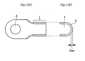
Figs. 1(A) and 1(B) illustrate a terminal used to
investigate moldability into a terminal. Fig. 1(A) shows
a front view of the terminal, and Fig. 1(B) shows an edge
face (end) view at the right side of the terminal shown in
Fig. 1(A).
DETAILED DESCRIPTION
According to the present invention, the following
means are provided:
Herein, the "space factor" means the ratio (%) of
the volume occupied by crystal grains having a crystal
grain size of 30 µm or less, of the total volume of the
crystalline structure.
The inventors of the present invention, having
studied an aluminum alloy material that occurs no cracks
by molding into a terminal, have found that materials
having a crystalline structure containing a higher
proportion of crystal grains smaller in size (diameter)
show better terminal moldability. The present invention
has been completed through intensive studies thereafter.
The space factor of the crystal grains having a
crystal grain size of 30 µm or less, in the crystalline
structure, is defined to be 30% or more in the present
invention. This is because cracks may be readily formed
at the terminal bent portion, by molding into the terminal,
when the space factor of the crystal grains having a
crystal grain size of 30 µm or less, is less than 30%.
There is no particular upper limit in the space factor of
the crystal grains having a crystal grain size of 30 µm or
less, but it is generally 80% or less.
While any electrically-conductive aluminum alloy may
be used for the aluminum alloy material of the present
invention, in particular, an Al-Zr alloy, an Al-Zr based
alloy, and an Al-Mg-Si based alloy are preferable, since
they are excellent in anti-stress relaxation properties
with required electrical conductivity.
A conductor-holding force decreases by a temperature
increase in use, to increase contact resistance between
the terminal and conductor, when the aluminum alloy
material to be used in the terminal has poor anti-stress
relaxation properties. The anti-stress relaxation
properties are enhanced in a highly heat-resistant alloy
or high-strength alloy.
Zr is precipitated as an Al-Zr compound in the Al-Zr
alloy according to the item (2), to enhance heat
resistance, thereby improving the anti-stress relaxation
properties. High electrical conductivity is maintained in
this alloy by suppressing the content of Zr.
The content of Zr is defined to be 0.02 to 0.15% by
mass in the Al-Zr alloy, because the effect of adding Zr
cannot be sufficiently obtained when the content is less
than 0.02% by mass, while high conductivity (57% IACS or
more) cannot be maintained when the content exceeds 0.15%
by mass.
The Al-Zr-based alloy according to the item (3) is
an alloy, in which heat resistance is remarkably enhanced
by increasing the content of Zr, and in which mechanical
strength is enhanced by allowing at least one of Be, Fe,
Si, and Cu to be contained in the alloy, thereby highly
improving the anti-stress relaxation properties.
The content of Zr is defined within the range of
0.20 to 0.45% by mass in the Al-Zr-based alloy, because
high anti-stress relaxation properties cannot be obtained
when the content is less than 0.20% by mass, while
conductivity (50% IACS or more) required for the terminal
cannot be attained when the content exceeds 0.45% by mass,
to decrease moldability into the terminal. In addition,
Zr is so expensive that it is disadvantageous with respect
to manufacturing cost. A particularly preferable content
of Zr is in the range of 0.30 to 0.35% by mass.
In the Al-Zr-based alloy, beryllium (Be) forms a
solid solution, to enhance mechanical strength, and
accelerates precipitation of Zr, to enhance heat
resistance. The content of Be is defined within the range
of 0.01 to 0.05% by mass, because a content of less than
0.01% does not sufficiently give the effect of adding Be,
while electrical conductivity decreases when the content
exceeds 0.05% by mass. A particularly preferable content
of Be is within the range of 0.02 to 0.04% by mass.
Fe enhances mechanical strength, by allowing Fe to
precipitate as an Al-Fe compound. The content of Fe is
defined within the range of 0.10 to 0.30% by mass, because
the effect of adding Fe cannot be sufficiently obtained
when the content is less than 0.10% by mass, while
moldability into the terminal decreases when the content
exceeds 0.30% by mass. A particularly preferable content
of Fe is within the range of 0.15 to 0.20% by mass.
Si enhances mechanical strength, by forming a solid
solution or precipitates, or it enhances mechanical
strength by accelerating precipitation of a fine Al-Fe
compound. The content of Si is defined to 0.06 to 0.20%
by mass, because the effect of adding Si cannot be
sufficiently obtained when the content is less than 0.06%
by mass, while moldability of the material decreases when
the content exceeds 0.20% by mass. A particularly
preferable content of Si is within the range of 0.06 to
0.15% by mass.
Cu enhances mechanical strength, by forming a solid
solution. The content of Cu is defined within the range
of 0.10 to 0.30% by mass, because the effect of adding Cu
cannot be sufficiently obtained when the content is less
than 0.10% by mass, while moldability and electrical
conductivity of the material are decreased when the
content exceeds 0.30% by mass.
In the Al-Mg-Si based alloy according to the item
(4), mechanical strength is enhanced by precipitating a
Mg-Si compound between Mg and Si, and by forming a solid
solution or precipitates among at least one of Fe, Cu, and
Mn, and at least one of Cr, Zn, and Ti serve to enhance
heat resistance, thereby improving the anti-stress
relaxation properties of the alloy. Fe also has an effect
to enhance heat resistance, while Mn also serves to
enhance corrosion resistance.
The contents of Mg and Si are defined within the
ranges of Mg 0.35 to 1.5% by mass, and Si 0.30 to 1.2% by
mass, respectively, in this alloy, because the effect of
adding these elements cannot be sufficiently obtained when
the content of either of them is below the ranges
described above, while cracks are occurred after casting,
or moldability of the material decreases, when the content
of either of them exceeds the ranges described above. Si
also has an effect to enhance mechanical strength, by
accelerating to precipitate a fine Al-Fe compound.
The contents of Fe, Cu, and Mn are defined in the
ranges of Fe 0.10 to 1.00% by mass, Cu 0.10 to 0.40% by
mass, and Mn 0.02 to 0.80% by mass, respectively, in this
alloy, because the effect of adding these elements cannot
be sufficiently obtained when the content of any one of
these elements is below the ranges described above, while
moldability of the material decreases when the content of
any one of the elements exceeds the ranges as described
above.
The contents of Cr, Zn, and Ti are defined within
the range of Cr 0.02 to 0.40% by mass, Zn 0.08 to 0.30% by
mass, and Ti 0.01 to 0.20% by mass, respectively, because
the effects of adding these elements cannot be
sufficiently obtained when the content of any one of them
is below the ranges described above, while casting
property decreases when the content of any one of them
exceeds the ranges described above.
The aluminum alloy materials for use in a terminal
according to the items (1) to (4) can be worked through
conform extrusion, or cold-rolling after usual hot-extrusion
or hot-rolling, into sheet materials. These
sheet materials and the like can be molded into the
terminal.
When a molten liquid aluminum alloy is cast into a
billet by a semicontinuous casting method and the
resulting billet is hot-rolled and then cold-rolled, to
obtain a sheet material; or when a molten liquid aluminum
alloy is cast into a plate ingot by a semicontinuous
casting method and the resulting ingot is hot-rolled and
then cold-rolled, into a sheet material, the crystal grain
size can be controlled to fall within the prescribed range
defined in the present invention, by adjusting the
conditions of heat treatment(s) applied in the midway of
cold-rolling. In this case, a crystal grain-fining agent,
such as a Ti-B compound, can be used.
The heat treatment condition applied in the midway
of cold-rolling is preferably at 350 to 500°C for 3 to 5
hours, and the crystal grain size may be simply controlled
by selecting the heat treatment conditions.
Examples of the preferable production conditions
that hardly cause cracks on the resulting sheet include
hot extrusion at a preferable extrusion initiation
temperature of 450 to 550°C, with a preferable extrusion
ratio of 20 to 200; and hot-rolling at a preferable
rolling initiation temperature of 350 to 550°C, with a
preferable rolled reduction ratio of 30% or more at one
rolling. The preferable cold-rolling initiation
temperature is in the range from normal temperature to
120°C, with a preferable reduction ratio of 30% or more in
one rolling.
Since conform extrusion can give the crystalline
structure defined in the present invention (30% or more of
the space factor of the crystal grains having a crystal
grain size of 30 µm or less) after such an extrusion, no
special controlling (adjustment) of the crystal grain size
as described above is required, to achieve excellent
productivity. In the case of conform extrusion, an
extrusion temperature (the temperature of the extruded
material at the outlet) that hardly cause cracks on the
resulting sheet, is preferably 400 to 550°C, and
particularly preferably 460 to 530°C.
The aluminum alloy material of the present invention
is particularly suitable for a terminal for an automobile
harness wire made of an aluminum alloy for flowing a large
magnitude of electric current.
The aluminum alloy material of the present invention,
for use in a terminal, is excellent in terminal
formability, and it can give a high-quality terminal
having no crack or the like with high yield, since the
alloy comprises a crystalline structure having 30% or more
of a space factor of the crystal grains having a crystal
grain size of 30 µm or less. A terminal excellent in
sustained electrical connection can be obtained, by using
a highly conductive Al-Zr alloy, Al-Zr-based alloy, or Al-Mg-Si-based
alloy having high anti-stress relaxation
properties, as the aluminum alloy. Since the crystalline
structure as defined in the present invention can be
obtained by conform extrusion after such an extrusion
process, no special adjustment of the crystal grain size
is required, to achieve excellent productivity.
Accordingly, the material of the present invention worked
according to conform extrusion can afford excellent
productivity by omitting treatment such as a heat
treatment for adjusting the crystal grain size.
Accordingly, the present invention exhibits remarkable
effects in industrial applications.
The present invention will be described in more
detail based on examples given below, but the present
invention is not limited by these examples.
Example
(Example 1)
Molten liquids of aluminum alloys (Nos. A to E),
having the compositions shown in Table 1, were prepared,
respectively, by adding Zr to an aluminum ingot (JIS 1N90)
for electric appliances. These molten liquids were
processed into rough drawing wires of diameter 9.5 mm, by
a belt-and-wheel-type continuous cast-rolling method. The
resultant rough drawing wires were worked into a sheet
material of thickness 2.0 mm and width 60 mm, by conform
extrusion. The temperature of the sheet materials during
extrusion was adjusted in the range of 480 to 510°C.
Resultantly, the alloy materials according to the item (1)
or (2) above were obtained.
(Example 2)
The sheet materials of thickness 2.0 mm were
produced in the same manner as in Example 1, except that
the molten liquids of the aluminum alloys (Nos. F to O),
having the compositions shown in Table 1, were provided,
respectively. Resultantly, the alloy materials according
to the item (1) or (3) above were obtained.
(Example 3)
Sheet materials of thickness 2.0 mm were produced in
the same manner as in Example 1, except that molten
liquids of the aluminum alloys (Nos. P to T), having the
compositions shown in Table 1, were provided, respectively.
Resultantly, the alloy materials according to the item (1)
or (4) above were obtained.
(Comparative Example 1)
The molten liquids of the Nos. A, F, K, P, and S
aluminum alloys, having the compositions as shown in Table
1, were cast into plate ingots by a semicontinuous casting
method. The resulting ingots were hot-rolled and then
cold-rolled, into sheet materials of thickness 2.0 mm.
The crystal grain size of the resulting sheet materials
was adjusted to fall outside the range defined in the
present invention, by applying two separate heat
treatments in the midway of cold-rolling and the
conditions in the heat treatment ware properly controlled.
Each sheet material produced in Examples 1 to 3 and
Comparative Example 1 was molded into a terminal of the
shape as shown in Figs. 1(A) and 1(B), to investigate
moldability into the terminal.
In Figs. 1(A) and 1(B), the reference numeral 1
denotes a conductor-holding part, the reference numeral 2
denotes a bent portion, and the reference numeral 3
denotes a bolt through-hole. This terminal corresponds to
an automobile battery electrode terminal (part mark BA,
with a nominal number 508), as defined in JIS D 5403 1989.
Moldability into terminal was investigated by the
incidence (number) of cracks of the bent portion 2, with
respect to 10 terminals obtained. The results were
evaluated as good in moldability into terminal when no
terminal had cracks, and as poor when at least one
terminal had cracks. The results are shown in Tables 2
and 3 as the resulting number of cracks.
The space factor of the crystal grains having a
crystal grain size of 30 µm or less is also listed in
Tables 2 and 3.
The crystal grain size was measured according to JIS
H 0501 (cut method), and the space factor of the crystal
grains having a crystal grain size of 30 µm or less was
determined based on the measured results. The measured
surface was ground into a specular surface by a buff,
followed by removing the surface layer to a depth of
several micrometers, by electropolishing.
| Alloy No. | Zr mass % | Mg mass % | Si mass % | Be mass % | Fe mass % | Cu mass % | Mn mass % | Cr mass % | Zn mass % | Ti mass % |
| A | 0.08 | - | - | - | - | - | - | - | - | - |
| B | 0.03 | - | - | - | - | - | - | - | - | - |
| C | 0.13 | - | - | - | - | - | - | - | - | - |
| D | 0.02 | - | - | - | - | - | - | - | - | - |
| E | 0.15 | - | - | - | - | - | - | - | - | - |
| F | 0.32 | - | 0.10 | - | 0.15 | - | - | - | - | - |
| G | 0.40 | - | 0.12 | 0.05 | 0.18 | - | - - | - | - | - |
| H | 0.20 | - | - | 0.02 | - | - | - | - | - | - |
| I | 0.36 | - | 0.15 | 0.04 | 0.19 | - | - | - | - | - |
| J | 0.24 | - | - | 0.02 | 0.10 | - | - | - | - | - |
| K | 0.32 | - | 0.10 | 0.03 | 0.28 | 0.20 | - | - | - | - |
| L | 0.25 | - | 0.06 | 0.02 | 0.15 | 0.11 | - | - | - | - |
| M | 0.45 | - | 0.19 | 0.05 | 0.30 | 0.30 | - | - | - | - |
| N | 0.29 | - | 0.08 | 0.02 | 0.21 | 0.14 | - | - | - | - |
| O | 0.37 | - | 0.14 | 0.04 | 0.24 | 0.24 | - | - | - | - |
| P | - | 0.35 | 0.30 | - | 0.50 | 0.10 | 0.03 | 0.03 | 0.10 | 0.01 |
| Q | - | 0.78 | 0.70 | - | 0.48 | 0.11 | 0.02 | 0.02 | 0.09 | 0.01 |
| R | - | 0.48 | 1.20 | - | 0.35 | 0.10 | 0.10 | 0.09 | 0.11 | 0.10 |
| S | - | 0.88 | 0.60 | - | 0.35 | 0.12 | 0.11 | 0.10 | 0.09 | 0.09 |
| T | - | 0.80 | 0.45 | - | 0.70 | 0.15 | 0.15 | 0.05 | 0.25 | 0.15 |
| Note: The balance was Al and unavoidable impurities. |
| Classification | Sample No. | Alloy No. | Producing method | Adjustment method of crystal grains | Space factor % of crystal grains of 30 µm or less | Number of cracks |
| Example 1 | 1 | A | Conform extrusion | No adjustment | 35 | 0 |
| 2 | B | 33 | 0 |
| 3 | C | 38 | 0 |
| 4 | D | 31 | 0 |
| 5 | E | 36 | 0 |
| Example 2 | 6 | F | Conform extrusion | No adjustment | 33 | 0 |
| 7 | G | 36 | 0 |
| 8 | H | 30 | 0 |
| 9 | I | 36 | 0 |
| 10 | J | 36 | 0 |
| 11 | K | 37 | 0 |
| 12 | L | 34 | 0 |
| 13 | M | 34 | 0 |
| 14 | N | 31 | 0 |
| 15 | O | 41 | 0 |
| Example 3 | 16 | P | Conform extrusion | No adjustment | 41 | 0 |
| | 17 | Q | 31 | 0 |
| 18 | R | 37 | 0 |
| 19 | S | 34 | 0 |
| 20 | T | 34 | 0 |
| Classification | Sample No. | Alloy No. | Producing method | Adjustment method of crystal grains | Space factor % of crystal grains of 30 µm or less | Number of cracks |
| Comparative Example 1 | 21 | A | Hot-rolling → Cold-rolling | Two heat treatments | 27 | 2 |
| 22 | F | 12 | 5 |
| 23 | K | 24 | 3 |
| 24 | P | 14 | 5 |
| 25 | S | 22 | 4 |
As is apparent from the results shown in Tables 2 and
3, the aluminum alloy material samples Nos. 1 to 20, of
the Examples according to the present invention, were
excellent in moldability into terminal, with no terminal
had cracks thereon, since the samples each had 30% or more
of the space factor of the crystal grains having a crystal
grain size of 30 µm or less. The samples were prepared by
conform extrusion and they were excellent in productivity,
since no heat-treatment or the like was required to adjust
the crystal grain size. Therefore, the overall evaluation
was very good.
In contrast, the samples for comparison Nos. 21 to
25, in Comparative Example 1, were poor in moldability
into terminal, due to less than 30% of the space factor of
the crystal grains having a crystal grain size of 30 µm or
less, with cracks occurred at the bent portion of the
terminal.
The anti-stress relaxation properties and electric
conductivity, which were required for a terminal, were
also measured with respect to the terminals of the present
invention.
A cable conductor made of an aluminum alloy was
fixed by compression on the conductor-holding part of the
terminal, the resulting terminal and the cable were heated
at 200°C for 40 hours, and electrical resistance (r)
between the terminal and the cable after heating was
measured. The anti-stress relaxation properties were
evaluated by obtaining the ratio (r/R) between the
electrical resistance (R) before heating the terminal and
the cable and the electrical resistance (r) after heating.
All the samples Nos. 1 to 20 of the examples according to
the present invention showed good characteristics with the
ratio (r/R) of 0.9 or more, showing that the samples Nos.
1 to 20 had high heat-resistance or mechanical strength.
Electrical conductivity also satisfied a level of 50% IACS
or more required for a terminal (as measured in accordance
with JIS H 0505).
Similarly, no crack or the like was occurred when
the aluminum alloy material of the present invention was
molded into terminals of other configurations (nominal Nos.
608 and 708), with good moldability.
Having described our invention as related to the
present embodiments, it is our intention that the
invention not be limited by any of the details of the
description, unless otherwise specified, but rather be
construed broadly within its spirit and scope as set out
in the accompanying claims.