EP1295813A2 - Container for welding wire - Google Patents
Container for welding wire Download PDFInfo
- Publication number
- EP1295813A2 EP1295813A2 EP02021262A EP02021262A EP1295813A2 EP 1295813 A2 EP1295813 A2 EP 1295813A2 EP 02021262 A EP02021262 A EP 02021262A EP 02021262 A EP02021262 A EP 02021262A EP 1295813 A2 EP1295813 A2 EP 1295813A2
- Authority
- EP
- European Patent Office
- Prior art keywords
- container
- container according
- wire
- lid
- side wall
- Prior art date
- Legal status (The legal status is an assumption and is not a legal conclusion. Google has not performed a legal analysis and makes no representation as to the accuracy of the status listed.)
- Granted
Links
Images


Classifications
-
- B—PERFORMING OPERATIONS; TRANSPORTING
- B65—CONVEYING; PACKING; STORING; HANDLING THIN OR FILAMENTARY MATERIAL
- B65H—HANDLING THIN OR FILAMENTARY MATERIAL, e.g. SHEETS, WEBS, CABLES
- B65H49/00—Unwinding or paying-out filamentary material; Supporting, storing or transporting packages from which filamentary material is to be withdrawn or paid-out
- B65H49/02—Methods or apparatus in which packages do not rotate
- B65H49/04—Package-supporting devices
- B65H49/06—Package-supporting devices for a single operative package
- B65H49/08—Package-supporting devices for a single operative package enclosing the package
-
- B—PERFORMING OPERATIONS; TRANSPORTING
- B23—MACHINE TOOLS; METAL-WORKING NOT OTHERWISE PROVIDED FOR
- B23K—SOLDERING OR UNSOLDERING; WELDING; CLADDING OR PLATING BY SOLDERING OR WELDING; CUTTING BY APPLYING HEAT LOCALLY, e.g. FLAME CUTTING; WORKING BY LASER BEAM
- B23K9/00—Arc welding or cutting
- B23K9/12—Automatic feeding or moving of electrodes or work for spot or seam welding or cutting
- B23K9/133—Means for feeding electrodes, e.g. drums, rolls, motors
- B23K9/1333—Dereeling means
-
- B—PERFORMING OPERATIONS; TRANSPORTING
- B65—CONVEYING; PACKING; STORING; HANDLING THIN OR FILAMENTARY MATERIAL
- B65D—CONTAINERS FOR STORAGE OR TRANSPORT OF ARTICLES OR MATERIALS, e.g. BAGS, BARRELS, BOTTLES, BOXES, CANS, CARTONS, CRATES, DRUMS, JARS, TANKS, HOPPERS, FORWARDING CONTAINERS; ACCESSORIES, CLOSURES, OR FITTINGS THEREFOR; PACKAGING ELEMENTS; PACKAGES
- B65D5/00—Rigid or semi-rigid containers of polygonal cross-section, e.g. boxes, cartons or trays, formed by folding or erecting one or more blanks made of paper
- B65D5/42—Details of containers or of foldable or erectable container blanks
- B65D5/44—Integral, inserted or attached portions forming internal or external fittings
- B65D5/50—Internal supporting or protecting elements for contents
- B65D5/5028—Elements formed separately from the container body
- B65D5/5035—Paper elements
- B65D5/5045—Tubular lining and supporting elements
-
- B—PERFORMING OPERATIONS; TRANSPORTING
- B65—CONVEYING; PACKING; STORING; HANDLING THIN OR FILAMENTARY MATERIAL
- B65D—CONTAINERS FOR STORAGE OR TRANSPORT OF ARTICLES OR MATERIALS, e.g. BAGS, BARRELS, BOTTLES, BOXES, CANS, CARTONS, CRATES, DRUMS, JARS, TANKS, HOPPERS, FORWARDING CONTAINERS; ACCESSORIES, CLOSURES, OR FITTINGS THEREFOR; PACKAGING ELEMENTS; PACKAGES
- B65D5/00—Rigid or semi-rigid containers of polygonal cross-section, e.g. boxes, cartons or trays, formed by folding or erecting one or more blanks made of paper
- B65D5/42—Details of containers or of foldable or erectable container blanks
- B65D5/44—Integral, inserted or attached portions forming internal or external fittings
- B65D5/50—Internal supporting or protecting elements for contents
- B65D5/5028—Elements formed separately from the container body
- B65D5/5097—Central hubs or shafts
-
- B—PERFORMING OPERATIONS; TRANSPORTING
- B65—CONVEYING; PACKING; STORING; HANDLING THIN OR FILAMENTARY MATERIAL
- B65D—CONTAINERS FOR STORAGE OR TRANSPORT OF ARTICLES OR MATERIALS, e.g. BAGS, BARRELS, BOTTLES, BOXES, CANS, CARTONS, CRATES, DRUMS, JARS, TANKS, HOPPERS, FORWARDING CONTAINERS; ACCESSORIES, CLOSURES, OR FITTINGS THEREFOR; PACKAGING ELEMENTS; PACKAGES
- B65D71/00—Bundles of articles held together by packaging elements for convenience of storage or transport, e.g. portable segregating carrier for plural receptacles such as beer cans or pop bottles; Bales of material
- B65D71/0088—Palletisable loads, i.e. loads intended to be transported by means of a fork-lift truck
- B65D71/0092—Palletisable loads, i.e. loads intended to be transported by means of a fork-lift truck provided with one or more rigid supports, at least one dimension of the supports corresponding to a dimension of the load, e.g. skids
- B65D71/0096—Palletisable loads, i.e. loads intended to be transported by means of a fork-lift truck provided with one or more rigid supports, at least one dimension of the supports corresponding to a dimension of the load, e.g. skids the dimensions of the supports corresponding to the periphery of the load, e.g. pallets
-
- B—PERFORMING OPERATIONS; TRANSPORTING
- B65—CONVEYING; PACKING; STORING; HANDLING THIN OR FILAMENTARY MATERIAL
- B65D—CONTAINERS FOR STORAGE OR TRANSPORT OF ARTICLES OR MATERIALS, e.g. BAGS, BARRELS, BOTTLES, BOXES, CANS, CARTONS, CRATES, DRUMS, JARS, TANKS, HOPPERS, FORWARDING CONTAINERS; ACCESSORIES, CLOSURES, OR FITTINGS THEREFOR; PACKAGING ELEMENTS; PACKAGES
- B65D81/00—Containers, packaging elements, or packages, for contents presenting particular transport or storage problems, or adapted to be used for non-packaging purposes after removal of contents
- B65D81/02—Containers, packaging elements, or packages, for contents presenting particular transport or storage problems, or adapted to be used for non-packaging purposes after removal of contents specially adapted to protect contents from mechanical damage
- B65D81/05—Containers, packaging elements, or packages, for contents presenting particular transport or storage problems, or adapted to be used for non-packaging purposes after removal of contents specially adapted to protect contents from mechanical damage maintaining contents at spaced relation from package walls, or from other contents
-
- B—PERFORMING OPERATIONS; TRANSPORTING
- B65—CONVEYING; PACKING; STORING; HANDLING THIN OR FILAMENTARY MATERIAL
- B65D—CONTAINERS FOR STORAGE OR TRANSPORT OF ARTICLES OR MATERIALS, e.g. BAGS, BARRELS, BOTTLES, BOXES, CANS, CARTONS, CRATES, DRUMS, JARS, TANKS, HOPPERS, FORWARDING CONTAINERS; ACCESSORIES, CLOSURES, OR FITTINGS THEREFOR; PACKAGING ELEMENTS; PACKAGES
- B65D85/00—Containers, packaging elements or packages, specially adapted for particular articles or materials
- B65D85/02—Containers, packaging elements or packages, specially adapted for particular articles or materials for annular articles
- B65D85/04—Containers, packaging elements or packages, specially adapted for particular articles or materials for annular articles for coils of wire, rope or hose
-
- B—PERFORMING OPERATIONS; TRANSPORTING
- B65—CONVEYING; PACKING; STORING; HANDLING THIN OR FILAMENTARY MATERIAL
- B65H—HANDLING THIN OR FILAMENTARY MATERIAL, e.g. SHEETS, WEBS, CABLES
- B65H57/00—Guides for filamentary materials; Supports therefor
- B65H57/18—Guides for filamentary materials; Supports therefor mounted to facilitate unwinding of material from packages
-
- B—PERFORMING OPERATIONS; TRANSPORTING
- B65—CONVEYING; PACKING; STORING; HANDLING THIN OR FILAMENTARY MATERIAL
- B65D—CONTAINERS FOR STORAGE OR TRANSPORT OF ARTICLES OR MATERIALS, e.g. BAGS, BARRELS, BOTTLES, BOXES, CANS, CARTONS, CRATES, DRUMS, JARS, TANKS, HOPPERS, FORWARDING CONTAINERS; ACCESSORIES, CLOSURES, OR FITTINGS THEREFOR; PACKAGING ELEMENTS; PACKAGES
- B65D2571/00—Bundles of articles held together by packaging elements for convenience of storage or transport, e.g. portable segregating carrier for plural receptacles such as beer cans, pop bottles; Bales of material
- B65D2571/00006—Palletisable loads, i.e. loads intended to be transported by means of a fork-lift truck
- B65D2571/00055—Clapping elements, also placed on the side
-
- B—PERFORMING OPERATIONS; TRANSPORTING
- B65—CONVEYING; PACKING; STORING; HANDLING THIN OR FILAMENTARY MATERIAL
- B65D—CONTAINERS FOR STORAGE OR TRANSPORT OF ARTICLES OR MATERIALS, e.g. BAGS, BARRELS, BOTTLES, BOXES, CANS, CARTONS, CRATES, DRUMS, JARS, TANKS, HOPPERS, FORWARDING CONTAINERS; ACCESSORIES, CLOSURES, OR FITTINGS THEREFOR; PACKAGING ELEMENTS; PACKAGES
- B65D2571/00—Bundles of articles held together by packaging elements for convenience of storage or transport, e.g. portable segregating carrier for plural receptacles such as beer cans, pop bottles; Bales of material
- B65D2571/00006—Palletisable loads, i.e. loads intended to be transported by means of a fork-lift truck
- B65D2571/00067—Local maintaining elements, e.g. partial packaging, shrink packaging, shrink small bands
- B65D2571/00074—Stabilising or reinforcing columns
-
- B—PERFORMING OPERATIONS; TRANSPORTING
- B65—CONVEYING; PACKING; STORING; HANDLING THIN OR FILAMENTARY MATERIAL
- B65H—HANDLING THIN OR FILAMENTARY MATERIAL, e.g. SHEETS, WEBS, CABLES
- B65H2701/00—Handled material; Storage means
- B65H2701/50—Storage means for webs, tapes, or filamentary material
- B65H2701/53—Adaptations of cores or reels for special purposes
- B65H2701/534—Stackable or interlockable reels or parts of reels
Definitions
- the invention relates to a container for welding wire.
- a container for welding wire serves to accommodate a bulk welding wire coil used in automatic and semi-automatic welding processes.
- the container has two primary functions. First, the container serves as a means for transporting the welding wire coil and protecting it. In particular, the container is to be made sufficiently rigid to prevent the individual turns of the welding wire coil to be displaced one relatively to the other. Second, the container serves as take-out device allowing continuous withdrawal of the welding wire from the coil.
- the wire When the container is completely filled with the wire, the wire exerts a radial pressure into the side wall which tends to deform the polygonal container.
- EP 0 636 098 B1 suggests to place a stabilising device at each corner of the side wall which device extends upwardly from the bottom and comprises angular elements of folded cardboard and wooden boards accommodated in the angular elements.
- a further welding wire container which is known from WO 98/52844 has a body and a lid made of cardboard with two inspection windows allowing a limited view into the interior of the body.
- the container is shipped with the lid.
- the container requires to first remove the lid from the container, in order to insert a wire conduit device.
- the wire conduit device defines a separate, additional guide means between a retainer lying on the wire coil and the lid and it acts as a support frame for the lid.
- the end of the wire is to be pulled through a sleeve of the wire conduit device and a guiding hole in the lid.
- the lid is re-mounted to the top of the container so as to close it again and prevent contamination of the interior of the container.
- the described procedure from opening to re-mounting of the lid is time-consuming. Further, it cannot be excluded that the container remains opened for some hours or days after removing the lid allowing dirt and moisture to enter into the container so that the wire is soiled or immediately oxidises. A further reason that the container according to the state of the art is opened by the purchaser of the container is that the inspection windows do not allow a complete inspection of the interior for initiating the welding process or during the welding process, in order to check the quality of the wire and the remaining content of the container, respectively.
- the invention provides a container for welding wire comprising a box-like body having a bottom and a side wall, the side wall having a polygonal cross section with corners, and comprising stabilising elements arranged at at least some of the corners.
- the stabilising elements extend upwardly from the bottom and have an outer shell portion comprising a comer portion facing the adjacent side wall and an inner portion facing an interior of the container for housing welding wire.
- the comer portion has a shape adapted to the shape of the adjacent comer.
- the inner portion defines a continuous inner wall.
- the present invention provides a container with cheap stabilising elements of superior stability which prevent the container from deformation and which allows a more continuous feed of the wire. Further, the corner supports still leave enough empty space in the comers of the polygonal body in which tips of a retainer braking element, made of plastic, wire or any other material, can extend beyond the wire coil to prevent wire strands from lifting along an outer perimeter of the wire coil.
- the present invention further provides a container for welding wire, comprising a box-like body having a bottom and a side wall, the side wall having a polygonal cross section with corners, and comprising stabilising elements arranged at at least some of the corners.
- the stabilising elements extend upwardly from the bottom and have an outer shell portion comprising a corner portion facing the adjacent side wall and an inner portion facing an interior of the container for housing welding wire.
- the corner portion tapers towards an outer edge contacting the adjacent corner, and the corner portion and the inner portion define an integral piece.
- the invention uses the effect that the radial pressure is used to stabilise the outer shape of the body by transmitting the radial pressure directly into the corner and not into the flat wall portions between two adjacent corners.
- the inner wall is continuous and not slitted as known from EP 0 636 098 B1 so that the inner wall has a high stability and transmits the force via the corner portions into the body's corner.
- the above effect is also achieved by the corner and the inner portion defining an integral piece. This further stabilises the position of the inner portion so that a lateral yielding or displacement of the inner portion due to the radial pressure which can slightly amend its direction during shipping can be avoided.
- the comer portion continues in one piece with the inner portion to have a circumferentially closed outer shell portion.
- the stabilising elements do not have a slitted outer shell portion or outer wall and have an increased stability.
- the stabilising elements have a cross-shape with a rounded inner portion or, more generally, an inner portion bulging toward the interior and with a corner contact portion having a shape adapted to the associated corner of the side wall.
- the stabilising elements act as a supporting inner box frame.
- the welding wire contacts the stabilising elements at the rounded inner portion with low friction between the wire and the stabilising elements allowing a very continuous feed. Due to the rounded geometry, the stabilising elements obtain a high resistance to the forces exerted by the wire. Further, the forces generated by the wire is directly transmitted into the comer portions and into the comer.
- the rounded inner portion also avoids buckling of the stabilising elements under the radial and, when double-stacked, axial loads.
- the corner contact portion is not rounded but adapted to the associated corner so that the side wall and the stabilising element contact each other at a large surface area and transmits the forces into the comer of the body.
- the comer contact portion supports the corner of the side wall so that the corner can maintain its original shape.
- the stabilising element is perfectly positioned in the corner of the body and is, thus, prevented from any displacement within the container.
- the angle defining the corner contact portion slightly differs from the angle defining the vertical corner of the side wall, both angles are preferably the same.
- the comer contact portion is defined by two flat portions of the stabilising element.
- the stabilising elements could be made from wood, metal (e.g. light metal) or any other material. Wood, however, absorbs and releases moisture, oxidising the wire and making it unusable. Therefore, the stabilising element is preferably made from metal cardboard and plastics and is preferably hollow to have a reduced weight.
- the body has a rectangular shape, e.g. a square shape.
- the contact portion is defined by two flat wall portions extending in an angle of 90° with respect to each other.
- the container when filled with welding wire is of such shape and such stability that containers of the same design and filled with welding wire can be double-stacked with a bottom of an upper container being placed on a lower container.
- the stabilising elements protrude over an upper end of the side wall, it is assured that the load of the upper container is firstly transmitted into the stabilising elements and not directly into the side walls which have a reduced stability.
- This important improvement is not limited to a container having stabilising elements as defined in claim 1. Rather, the stabilising elements protruding over the upper end of the side wall are an important inventive improvement for a container for welding wire per se.
- the present invention allows to have more than 250 kg of welding wire packed into a container according to the invention.
- One further embodiment of the invention provides an inner wall arranged between the wire and the stabilising elements.
- the inner wall circumscribes the wire by contacting the wire with its inner side. Its outer side is contacted by the stabilising elements.
- the inner wall which preferably has a circumferentially closed cross-section acts like a box in the box. The inner wall gives the wire a close axial guide and takes up the radial pressure exerted by the wire to transmit the pressure to the stabilising elements, only. Further, a wire coil has more contact points along its radial outer end.
- the invention further provides a container for welding wire, comprising a box-like body of any shape, e.g. cylindrical or polygonal, having a bottom and a sidewall and comprising a lid at the top of the body closing the container.
- the lid consists of transparent material allowing a visual inspection of the interior of the container.
- the lid and the body are of such shape and such stability that containers of the same design can be at least double-stacked with the bottom of the upper container standing on the lid of the lower container.
- the container according to the invention has, contrarily to the container shown in WO 98/52844, a lid made of one material which is transparent so that a complete inspection of the interior of the container is achieved, at any time, during storage, shipping and use.
- the lid itself is attached to the body during shipping and during the later unwinding of the wire.
- the one-piece lid is simple and cheap in its manufacture.
- the transparent lid allows the user to control the wire from outside without removing the lid so that contamination of the interior by opening the container can be avoided.
- the lid and the body are of such shape and stability that at least double-stacking of the containers when filled with the wire are allowed during shipping and storage. This important improvement is not limited to a container having stabilising elements with a shape defined in claim 1.
- the lid of the container according to the invention is only used once and is therefore always new for each container, a clean and perfect vision and inspection of the interior of the container is guaranteed. Further, as the lid of the container according to the invention is of one piece only its disposal or recycling is facilitated.
- the lid can be of glass, the preferred embodiment teaches that the lid is of plastics, e.g. from PE or PP, and moulded or stamped in one piece.
- the lid has an upper plate-shaped portion and a downwardly extending ring-shaped collar engaging around the outer periphery of the upper edge of the sidewall.
- the collar is able to give the body a certain support in the radial direction as the wire exerts radial forces into the body.
- the stabilising element may not only increase the stability of the container against radial but also against axial load. If the stabilising elements protrude over the upper end of the side wall, the collar extends downwardly to the upper end of the side wall to be fixed thereto. As the side wall of the body does not extend to the upper end of the body which is defined by the stabilising elements, the transparent collar closes the gap between the upper end of the side wall and the upper end of the stabilising elements so that it is possible to have a side view into the interior of the container by looking through the transparent collar.
- a seal is provided between the lid and the body preventing moisture and dirt from entering into the container.
- the seal it is not necessary to open the container after shipping and during use, the seal remains unbroken, and oxidation of the wire can be completely omitted.
- the seal is an adhesive tape or a tight plastic foil which further attaches the lid to the body.
- the adhesive tape can be wrapped around the lower edge of the ring-shaped collar and the outer periphery of the upper edge of the sidewall.
- An adhesive tape or tight plastic foil has a further advantage, especially when used with side walls made of cardboard. The user immediately can find out whether the container was opened before as the adhesive connection or the foil is at least partly destroyed.
- the container according to the invention may have a retainer for downholding the wire coil strands which retainer sits on the wire during shipping and during unwinding.
- the lid has a the wire-exiting hole, and the wire extends upwards from the retainer.
- a separate fitting means underneath the lid for fitting a conduit device as it is known from WO 98/52844 can be avoided.
- the wire conduit device for subsequent feeding of the welding machine can be directly fitted to the lid as the lid has enough stability. Further, opening of the lid only for the purpose of inserting a separate fitting means is superfluous.
- the preferred embodiment of the invention provides that, in the shipping state of the container in which the container is filled with welding wire, a wire end already extends outwardly from the container through a wire-exiting hole in the lid.
- the outwardly extending wire end is attached to the container.
- This specific arrangement of the wire end during shipping of the container allows an immediate start of the wire unwinding without removing the lid.
- the end of the wire extends through the wire-exiting hole, it is preferably attached to the lid by an adhesive tape or plastic foil which further seals the hole close and prevents moisture from entering into the container.
- the adhesive tape or plastic foil thus, has a double-function.
- the lid may have an upper plate-shaped portion with an upwardly protruding centre portion.
- This centre portion can be of convex shape.
- the centre portion gives the lid more stiffness facilitating to attach the fitting of a tube-shaped conduit device onto the lid.
- the protruding centre portion also helps aligning containers during stacking.
- the centre portion may have the function of a guiding cone. Further, a sideward displacement of stacked containers relative to each other during shipping can be avoided.
- the plate-shaped portion of the lid has a flat outer portion surrounding the protruding centre portion.
- the upper container stands on the flat outer portion of the lower container so that the protruding centre portion is not deformed.
- the flat outer portion may have a rough finish surface to disguise possible scratches caused by double-stacking and to increase the friction between stacked containers. Even if the surface is rough finished, the lid will be at least translucent in the flat outer portion allowing more light to fall into the container and improving the inspection of the container content through those portions of the lid which are not rough finished.
- the bottom of the lid may comprise a pallet so that the pallet of the upper container contacts the lid of the lower container during shipping or storage.
- a further option to avoid deformation of the filled container is to use a support means in form of a closed ring extending along the periphery of the body.
- the support means can be a reinforcing band or strip, preferably a tape like a adhesive tape wrapped around the outer periphery of the body.
- the tape can be the same tape which is used for sealing the lid and the body.
- the above defined transparent lid is, according to the preferred embodiment used in connection with the stabilising elements, explained above to generate a container of high stability allowing an excellent visual inspection.
- some of the above advantages can be achieved by the lid, only, so that a polygonal or cylindrical container with the transparent lid per se leads to an important improvement of a welding wire container.
- the invention provides a container for welding wire comprising a box-like body having a bottom and a side wall and comprising a lid at the top of the body for closing the container.
- the central core arranged on the bottom tapers in the upward direction.
- the core has a frusto-conical or pyramidal shape.
- the central core is hollow and of such shape that a plurality of such cores are able to be stacked one into another, the user of the containers is able to transport a high number of used cores for recycling or disposal at a minimum volume.
- the central core can be simply placed on the bottom without being fixed thereto in order to fulfill the above objects.
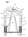
- a container for accommodating of welding wire W according to a first embodiment is shown in Figure 1.
- the container comprises as main components a box-like body 10 having a bottom 12 which is supported by a pallet 14 defining a lower part of the bottom.
- the box-like body further has a side wall 16 which is, in the circumferential direction, closed.
- the bottom and the side wall are, according to the preferred embodiment, made from cardboard.
- the pallet 14 is of wood.
- a coil 18 of welding wire W is arranged within the container.
- the upper end of the wire extends upwards from the retainer 20 to a lid 22 which closes the container and which is placed on top of the box-like body 16 which latter having an open upper side.
- the lid 22 has a central wire-exiting hole 24 through which the wire end 24 extends even in the shipping state which is shown in Figure 1.
- the wire-exiting hole is defined by a reinforcement ring in the form of a rivet 26 which is attached to the lid 22 (see also Fig. 5).
- the lid 22 is of transparent material only (with the exception of the rivet 26) and is made from one piece.
- the lid is of plastics, e.g. PE or PP, which has a thickness of only 1 or 2 mm and is moulded, e.g. injection-moulded, in one-piece or stamped and pressed by use of heated moulds.
- the lid has an upper plate-shaped portion 28 and a ring-shaped collar 30 which extends downwardly from the plate-shaped portion 28 and which engages around the outer periphery 32 (see Figure 4) of the upper edge 34 of the side wall 16.
- the upper end 36 of the side wall 16 may extend up to the plate-shaped portion 28 to contact it.
- the upper end 36 is distanced from the plate-shaped portion 28.
- the lid 28 lies on stabilising elements 40 which are part of the body and extend upwardly from the bottom 12 to the lid 28 protruding over the upper end 36 of the sidewall 16 to the plate-shape portion 28.
- the stabilising elements 40 are made from cardboard and are hollow.
- the collar 30 extends downwardly to the upper end 36 of the side wall 16 and overlaps the upper edge 34 and is fixed to the side wall at its upper edge 34.
- an adhesive, preferably transparent tape or tight plastic foil 42 is wrapped around the lower end 44 of the ring-shaped collar 30 and the outer periphery of the upper edge 34 of the side wall 16.
- the adhesive tape or foil 42 further acts as a seal preventing moisture from entering into the container.
- a visual inspection of the content of the container can be made from above (through the plate-shaped portion) or from the side (through the collar 30).
- the visual inspection from the side through the transparent collar thus allows visual inspection of the containers' interior even if the containers are stacked one on top of another during storage or transportation (see Figure 6).
- the container allows shipping and later fitting of a wire conduit device of a welding machine and withdrawal of the wire without opening of the container.
- the lid and the body are of such shape and such stability that containers of the same design can be stacked onto each other when filled with the wire so that the bottom of the upper container is placed on the lid of the lower container as can be seen in Figure 6.
- the horizontal braces 60 of the pallet 14 which define part of the body contact the lid close to its radial outer edge where the stabilising elements 40 are arranged. Therefore, the load of the upper container is transferred through the lid 22 into the stabilising elements 40 and, finally, to the ground.
- the wire end 24 is attached to the lid by an adhesive tape 66 which further sealingly closes the wire-exiting hole so as to prevent moisture from entering into the container.
- the adhesive tape 66 is only to be removed, and a fitting 68 of a conduit device is to be attached to the lid.
- the rivet 26 shown in Figure 5 may help to securely attach the fitting 68 to the lid 22.
- the upper plate-shaped portion 28 of the lid is completely plain.
- the upper plate-shaped portion 28 has a convex- or dome-shaped hollow centre portion 50 and a flat outer portion 52 which is ring-shaped and which surrounds the centre portion 50.
- the flat outer portion 52 may have a rough finish surface as seen in the embodiment according to Figure 5 whereas the protruding centre portion 50 is completely transparent. Even if the outer portion 52 is rough, this portion is at least translucent allowing more light to enter the interior of the container.
- the lid has a slightly conical shape by the collar 30 slightly tapering in the upward direction. This shape facilitates installation of the lid onto the body and allows stacking of a number of lids one into another and, thus, an easier transport for recycling or disposal. As the lid is of plastics which can be recycled and of one material only, the recycling or disposal is further facilitated.
- the lid may have ribs 98, for example on the lower side of the plate-shaped portion 28.
- the ribs 98 are formed on the plate-shaped 28 portion and are formed when moulding or forming the lid.
- the body has a polygonal, more precisely a square shape as can be seen from Figure 3.
- Elongated stabilising elements 40 extending from the bottom 12 along the corresponding corner upwards to protrude over the upper end of the side wall are arranged at each comer 80 of the body 10.
- the stabilising elements have a rounded inner portion 82 in the form of a segment of a circle facing the interior of the container and a corner contact portion 84 which is defined by two flat sections 86 extending in an angle ⁇ of 90° with respect to each other and facing the adjacent side wall.
- the angle ⁇ corresponds to the angle of the comers 80 (some difference may be acceptable) between adjacent panels 116, 116', 116", 116''' of the side wall 16 so that the side wall 16 is contacted by the corner portion 84 over a large area.
- the stabilising elements 40 prevent bulging and deformation of the complete container caused by the pressure of the wire coil 70 acting in the radial outward direction.
- the stabilising elements 40 take up the pressure of the wire coil 70 to transmit it directly into the corners 80 so that the panels 116 to 116''' are not deformed. For that reason, the corner portion of each element tapers toward the outer edge of the element which edge contacts the adjacent corner. Further, the corner portion and the inner portion define an integral piece.
- the inner portion 82 defines a continuous inner wall, i.e. there is no elongated vertical slit provided in the inner portion 84. Rather, the inner portion is one piece.
- the comer portion 84 continues in one piece with the inner portion 82.
- the embodiment according to Figure 3 shows (like most of the other embodiments) stabilising elements 40 having a circumferentially closed outer shell portion 89 or outer wall defined by the outer surface of the comer portion 84 and the inner portion 82 which continue in one piece with each other. Due to the closed outer shell portion 89, the stability of the entire stabilising elements 40 and not only of the inner portion 82 is increased with respect to a cylindrical stabilising element which has a vertical slit or is open to its interior. With those embodiments comprising hollow stabilising elements, the outer shell portion 89 is always defined by a circumferentially closed, ring shaped outer wall.
- stabilising elements 40 do not have to be arranged in each corner 80. Especially if there are more than four comers, it is sufficient to have some corners 80 provided with stabilising elements 40. In order to allow double-stacking, at least three, preferably four comers 80 should have stabilising elements 40.
- a positioning element 41 preferably of wood and of only a few centimeters height, is nailed onto the bottom 12 and protrudes into the hollow stabilising element 40 to avoid any sideward displacement of the associated stabilising element 40 which is only stacked onto the positioning element 41 (see Figs. 2 and 3).
- each stabilising element 40 has its associated positioning element 41.
- the deformation of the container due to the load of the wire W can be further reduced by additional support means in the form of a close ring extending along the periphery of the body.
- This support means is, for example, a tape 90 wrapped around the outer periphery of the body (see Figure 4).
- the support means is, according to a preferred embodiment, arranged close to the upper end of the side wall 16.
- a central core 92 within the container 10 which is placed on the bottom extends upwardly through the middle of the wire coil.
- the core 92 has a frusto-conical or pyramidal shape and is of cardboard or plastics.
- the central core 92 is further hollow and of such shape that a plurality of the cores are to be stacked one into another for facilitating transportation for recycling or disposal (see Figure 7).
- the central core 92 is placed on the bottom without being fixed thereto. Due to the tapered shape of the core 92 the wire W comes out of the container at a smooth angle, gently touching on the whole length of the core 92.
- FIGs 8 and 9 show different shapes of stabilising elements 40' to 40"" wherein the stabilising elements 40' to 40"" according to Figure 8 are sturdy, i.e. full parts, and the stabilising elements 40' to 40"" according to Figure 9 are parts with a corresponding outer shell portion 89 but are hollow.
- Each stabilising element 40' to 40"" has a comer portion 84 adapted to the shape of the adjacent comer 80 so that the corner portion 84 contacts the adjacent side wall 16 over its entire surface.
- Each stabilising element 40' to 40”” has an inner portion 82 which bulges or protrudes towards the interior of the container.
- Common to all stabilising elements 40' to 40"" is that the elements are of one piece, only, and can be made from cardboard or plastics, metal or wood.
- the stabilising elements 40' have a square cross-sectional shape, two sides defining the corner portion 84 and two sides the inner portion 82.
- the inner portion 82 bulges or protrudes inwardly with respect to a line L through the circumferential ends of contact of the centre portion with the side wall 16.
- Stabilising elements 40" have a different inner portion 82 in the form of a half-circle with an indentation 130.
- Stabilising element 40''' has an inner portion 82 with two parallel sides protruding towards a tip for contacting the wire coil 70.
- Stabilising element 40" has a shape similar to the shape shown in Figure 3 but is of somewhat more compact design as the inner portion 84 is a half-circle whereas the embodiment according to Figure 3 has a rounded inner portion extending over more than 180°.
- stabilising elements 40' to 40''' of Fig. 10 correspond to those shown in Figure 9.
- Stabilising element 40''''' is similar to element 40' but has a stabilising rib 132 extending from the corner 80 towards the inner edge 134 contacting the wire coil 70. This allows a linear force transmission from the inner edge 134 to the corner 80.
- a retainer 20 made from wire.
- Outwardly protruding wire pieces 136 are provided for guiding the retainer 20 in the vertical direction and to avoid a circumferential displacement by engaging the stabilising elements 40' to 40"' and 40"".
- the indentation 130 accommodates one wire piece 136 to form a linear guide.
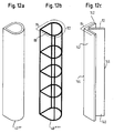
- the embodiment according to Figure 11 has an octagonal sidewall 16 with different stabilising elements 40"" and 40""" wherein the stabilising elements 40"" are hollow and the stabilising elements 40""" are sturdy parts, e.g. having a foamed core.
- the stabilising element 40"" is also shown in Figure 12a.
- Figure 12b shows a stabilising element 40''''''' in the form of a screen made from wire. Seen from the top, the inner portion 82 defines a continuous inner wall and the outer shell portion 89 is circumferentially closed.
- the stabilising element 140 according to Figure 12c is of different design as it has the shape of an arrow seen from the top.
- the inner portion 82 is a rib which protrudes like a bisecting line of an angle between the legs 142 defining the comer portions 84.
- the corner portion 84 tappers towards an outer edge 144 contacting the adjacent corner.
- a corner portion 84 and the inner portion 82 define an integral piece so that the force of the wire coil is taken up by edge 44 to be transmitted via the rib-like inner portion 82 immediately into the adjacent corner 80.
- the embodiments according to Figures 13 and 14 comprise an inner wall 160, 162, which is closed in circumferential direction without having a through-vertical slit.
- the inner wall 160 is a circular cylinder, and the inner wall 162 which is also circumferentially closed has an octagonal shape.
- Both inner walls 160, 162 circumscribe the wire coil 70, contact the wire coil by their inner sides and contact a stabilising element 240, 340 at their outer sides.
- the inner walls 160, 162 provide for a better guidance of the wire.
- only one stabilising element 240, 340 having a triangular shape is shown in the embodiments according to Figures 13 and 14, it should be clear that more or, preferably, all corners 80 have adjacent stabilising elements.
- the inner walls 160, 162 define a kind of inner frame, and the stabilising elements are the force transmitting connection to the outer frame in form of the body.
Abstract
Description
- The invention relates to a container for welding wire.
- A container for welding wire serves to accommodate a bulk welding wire coil used in automatic and semi-automatic welding processes. The container has two primary functions. First, the container serves as a means for transporting the welding wire coil and protecting it. In particular, the container is to be made sufficiently rigid to prevent the individual turns of the welding wire coil to be displaced one relatively to the other. Second, the container serves as take-out device allowing continuous withdrawal of the welding wire from the coil.
- When the container is completely filled with the wire, the wire exerts a radial pressure into the side wall which tends to deform the polygonal container.
- To avoid such deformation, EP 0 636 098 B1 suggests to place a stabilising device at each corner of the side wall which device extends upwardly from the bottom and comprises angular elements of folded cardboard and wooden boards accommodated in the angular elements.
- It is one object of the present invention to provide a container for welding wire which can be filled with an increased mass of welding wire, which is easy and cheap in its manufacture and which has a high stability avoiding deformation and squeezing of the body due to the load of the wire.
- It is a further object of the present invention to allow double stacking of containers when filled with welding wire without leading to a deformation of the lower container.
- A further welding wire container which is known from WO 98/52844 has a body and a lid made of cardboard with two inspection windows allowing a limited view into the interior of the body. The container is shipped with the lid. However, the container requires to first remove the lid from the container, in order to insert a wire conduit device. The wire conduit device defines a separate, additional guide means between a retainer lying on the wire coil and the lid and it acts as a support frame for the lid. After opening the container and inserting the wire conduit device, the end of the wire is to be pulled through a sleeve of the wire conduit device and a guiding hole in the lid. Finally, the lid is re-mounted to the top of the container so as to close it again and prevent contamination of the interior of the container. However, the described procedure from opening to re-mounting of the lid is time-consuming. Further, it cannot be excluded that the container remains opened for some hours or days after removing the lid allowing dirt and moisture to enter into the container so that the wire is soiled or immediately oxidises. A further reason that the container according to the state of the art is opened by the purchaser of the container is that the inspection windows do not allow a complete inspection of the interior for initiating the welding process or during the welding process, in order to check the quality of the wire and the remaining content of the container, respectively.
- It is a further object of the present invention to provide a container for welding wire which allows to unwind wire in a minimum set-up time. Furthermore, contamination and oxidation of the wire should be excluded by avoiding opening of the container.
- The invention provides a container for welding wire comprising a box-like body having a bottom and a side wall, the side wall having a polygonal cross section with corners, and comprising stabilising elements arranged at at least some of the corners. The stabilising elements extend upwardly from the bottom and have an outer shell portion comprising a comer portion facing the adjacent side wall and an inner portion facing an interior of the container for housing welding wire. The comer portion has a shape adapted to the shape of the adjacent comer. The inner portion defines a continuous inner wall.
- This arrangement avoids deformation of the coil and the body during transportation or stacking. When the wire is unwound from the coil and the height of the coil decreases, the above-mentioned retainer can easily descend, sliding unhindered along the stabilising elements. The present invention provides a container with cheap stabilising elements of superior stability which prevent the container from deformation and which allows a more continuous feed of the wire. Further, the corner supports still leave enough empty space in the comers of the polygonal body in which tips of a retainer braking element, made of plastic, wire or any other material, can extend beyond the wire coil to prevent wire strands from lifting along an outer perimeter of the wire coil.
- In order to achieve the above advantages the present invention further provides a container for welding wire, comprising a box-like body having a bottom and a side wall, the side wall having a polygonal cross section with corners, and comprising stabilising elements arranged at at least some of the corners. The stabilising elements extend upwardly from the bottom and have an outer shell portion comprising a corner portion facing the adjacent side wall and an inner portion facing an interior of the container for housing welding wire. The corner portion tapers towards an outer edge contacting the adjacent corner, and the corner portion and the inner portion define an integral piece.
- The invention uses the effect that the radial pressure is used to stabilise the outer shape of the body by transmitting the radial pressure directly into the corner and not into the flat wall portions between two adjacent corners. For this reason, the inner wall is continuous and not slitted as known from EP 0 636 098 B1 so that the inner wall has a high stability and transmits the force via the corner portions into the body's corner. The above effect is also achieved by the corner and the inner portion defining an integral piece. This further stabilises the position of the inner portion so that a lateral yielding or displacement of the inner portion due to the radial pressure which can slightly amend its direction during shipping can be avoided.
- According to the preferred embodiment, the comer portion continues in one piece with the inner portion to have a circumferentially closed outer shell portion. Thus, the stabilising elements do not have a slitted outer shell portion or outer wall and have an increased stability.
- In one preferred embodiment, the stabilising elements have a cross-shape with a rounded inner portion or, more generally, an inner portion bulging toward the interior and with a corner contact portion having a shape adapted to the associated corner of the side wall. The stabilising elements act as a supporting inner box frame. The welding wire contacts the stabilising elements at the rounded inner portion with low friction between the wire and the stabilising elements allowing a very continuous feed. Due to the rounded geometry, the stabilising elements obtain a high resistance to the forces exerted by the wire. Further, the forces generated by the wire is directly transmitted into the comer portions and into the comer. The rounded inner portion also avoids buckling of the stabilising elements under the radial and, when double-stacked, axial loads. The corner contact portion, however, is not rounded but adapted to the associated corner so that the side wall and the stabilising element contact each other at a large surface area and transmits the forces into the comer of the body. The comer contact portion supports the corner of the side wall so that the corner can maintain its original shape. Furthermore, the stabilising element is perfectly positioned in the corner of the body and is, thus, prevented from any displacement within the container.
- Although it, is possible that the angle defining the corner contact portion slightly differs from the angle defining the vertical corner of the side wall, both angles are preferably the same. The comer contact portion is defined by two flat portions of the stabilising element.
- The stabilising elements could be made from wood, metal (e.g. light metal) or any other material. Wood, however, absorbs and releases moisture, oxidising the wire and making it unusable. Therefore, the stabilising element is preferably made from metal cardboard and plastics and is preferably hollow to have a reduced weight.
- In one embodiment, the body has a rectangular shape, e.g. a square shape. The contact portion is defined by two flat wall portions extending in an angle of 90° with respect to each other.
- According to the preferred embodiment, the container when filled with welding wire is of such shape and such stability that containers of the same design and filled with welding wire can be double-stacked with a bottom of an upper container being placed on a lower container.
- When the stabilising elements protrude over an upper end of the side wall, it is assured that the load of the upper container is firstly transmitted into the stabilising elements and not directly into the side walls which have a reduced stability. This important improvement is not limited to a container having stabilising elements as defined in
claim 1. Rather, the stabilising elements protruding over the upper end of the side wall are an important inventive improvement for a container for welding wire per se. - The present invention allows to have more than 250 kg of welding wire packed into a container according to the invention.
- One further embodiment of the invention provides an inner wall arranged between the wire and the stabilising elements. The inner wall circumscribes the wire by contacting the wire with its inner side. Its outer side is contacted by the stabilising elements. The inner wall which preferably has a circumferentially closed cross-section acts like a box in the box. The inner wall gives the wire a close axial guide and takes up the radial pressure exerted by the wire to transmit the pressure to the stabilising elements, only. Further, a wire coil has more contact points along its radial outer end.
- As one further main object, the invention further provides a container for welding wire, comprising a box-like body of any shape, e.g. cylindrical or polygonal, having a bottom and a sidewall and comprising a lid at the top of the body closing the container. The lid consists of transparent material allowing a visual inspection of the interior of the container. The lid and the body are of such shape and such stability that containers of the same design can be at least double-stacked with the bottom of the upper container standing on the lid of the lower container.
- The container according to the invention has, contrarily to the container shown in WO 98/52844, a lid made of one material which is transparent so that a complete inspection of the interior of the container is achieved, at any time, during storage, shipping and use. The lid itself is attached to the body during shipping and during the later unwinding of the wire. The one-piece lid is simple and cheap in its manufacture. The transparent lid allows the user to control the wire from outside without removing the lid so that contamination of the interior by opening the container can be avoided. In order to allow the lid to be permanently placed onto the body, the lid and the body are of such shape and stability that at least double-stacking of the containers when filled with the wire are allowed during shipping and storage. This important improvement is not limited to a container having stabilising elements with a shape defined in
claim 1. - Although truncated, transparent cones are known which are placed onto the body after having removed a separate lid for shipping, and re-used many times over, such cones are not suitable to be used when shipping and do not allow double-stacking of the containers. Besides, the re-use of such cones for a long period of time compromises the vision of the interior of the container because of the inevitable accumulation of dirt, dust and grease from the environment in which these containers are normally being utilised.
- As the lid of the container according to the invention is only used once and is therefore always new for each container, a clean and perfect vision and inspection of the interior of the container is guaranteed. Further, as the lid of the container according to the invention is of one piece only its disposal or recycling is facilitated.
- Although the lid can be of glass, the preferred embodiment teaches that the lid is of plastics, e.g. from PE or PP, and moulded or stamped in one piece.
- The lid has an upper plate-shaped portion and a downwardly extending ring-shaped collar engaging around the outer periphery of the upper edge of the sidewall. Thus, the collar is able to give the body a certain support in the radial direction as the wire exerts radial forces into the body.
- The stabilising element may not only increase the stability of the container against radial but also against axial load. If the stabilising elements protrude over the upper end of the side wall, the collar extends downwardly to the upper end of the side wall to be fixed thereto. As the side wall of the body does not extend to the upper end of the body which is defined by the stabilising elements, the transparent collar closes the gap between the upper end of the side wall and the upper end of the stabilising elements so that it is possible to have a side view into the interior of the container by looking through the transparent collar.
- According to the preferred embodiment, a seal is provided between the lid and the body preventing moisture and dirt from entering into the container. As, according to the invention, it is not necessary to open the container after shipping and during use, the seal remains unbroken, and oxidation of the wire can be completely omitted.
- One example for the seal is an adhesive tape or a tight plastic foil which further attaches the lid to the body. The adhesive tape can be wrapped around the lower edge of the ring-shaped collar and the outer periphery of the upper edge of the sidewall. An adhesive tape or tight plastic foil has a further advantage, especially when used with side walls made of cardboard. The user immediately can find out whether the container was opened before as the adhesive connection or the foil is at least partly destroyed.
- The container according to the invention may have a retainer for downholding the wire coil strands which retainer sits on the wire during shipping and during unwinding. The lid has a the wire-exiting hole, and the wire extends upwards from the retainer. A separate fitting means underneath the lid for fitting a conduit device as it is known from WO 98/52844 can be avoided. According to the invention the wire conduit device for subsequent feeding of the welding machine can be directly fitted to the lid as the lid has enough stability. Further, opening of the lid only for the purpose of inserting a separate fitting means is superfluous.
- The preferred embodiment of the invention provides that, in the shipping state of the container in which the container is filled with welding wire, a wire end already extends outwardly from the container through a wire-exiting hole in the lid. The outwardly extending wire end is attached to the container. This specific arrangement of the wire end during shipping of the container allows an immediate start of the wire unwinding without removing the lid. If the end of the wire extends through the wire-exiting hole, it is preferably attached to the lid by an adhesive tape or plastic foil which further seals the hole close and prevents moisture from entering into the container. The adhesive tape or plastic foil, thus, has a double-function.
- The lid may have an upper plate-shaped portion with an upwardly protruding centre portion. This centre portion can be of convex shape. The centre portion gives the lid more stiffness facilitating to attach the fitting of a tube-shaped conduit device onto the lid. The protruding centre portion also helps aligning containers during stacking. The centre portion may have the function of a guiding cone. Further, a sideward displacement of stacked containers relative to each other during shipping can be avoided.
- The plate-shaped portion of the lid has a flat outer portion surrounding the protruding centre portion. In the stapled state of the containers, the upper container stands on the flat outer portion of the lower container so that the protruding centre portion is not deformed.
- The flat outer portion may have a rough finish surface to disguise possible scratches caused by double-stacking and to increase the friction between stacked containers. Even if the surface is rough finished, the lid will be at least translucent in the flat outer portion allowing more light to fall into the container and improving the inspection of the container content through those portions of the lid which are not rough finished.
- The bottom of the lid may comprise a pallet so that the pallet of the upper container contacts the lid of the lower container during shipping or storage.
- A further option to avoid deformation of the filled container is to use a support means in form of a closed ring extending along the periphery of the body. The support means can be a reinforcing band or strip, preferably a tape like a adhesive tape wrapped around the outer periphery of the body. The tape can be the same tape which is used for sealing the lid and the body.
- The above defined transparent lid is, according to the preferred embodiment used in connection with the stabilising elements, explained above to generate a container of high stability allowing an excellent visual inspection. However, some of the above advantages can be achieved by the lid, only, so that a polygonal or cylindrical container with the transparent lid per se leads to an important improvement of a welding wire container.
- The use of a cylindrical central core fixed to the body or movable is known. Such central cores also absorb vibrations while wire is being fed at very high speed. However, the existing cores with a cylindrical shape lead to the following problems. When most of the wire has been pulled out and only some remain in the lower part of the container, the wire comes out at a very sharp and odd angle which causes unwanted wire bending and unreliable welds. Further, the exiting wire scratches on the core upper edge, wearing the core which is normally made of cardboard and denting the edge. The wire itself may catch in the dents and jam.
- It is an important object of the present invention to provide a container with a central core arranged on the bottom and extending upwardly through the middle of the coil which core improves sorting wire layers in case one or more fall into the container. Furthermore, the container according to the invention should have a core avoiding unwanted wire bending during withdrawal of wire.
- In order to achieve the above object and to avoid the above disadvantages, the invention provides a container for welding wire comprising a box-like body having a bottom and a side wall and comprising a lid at the top of the body for closing the container. The central core arranged on the bottom tapers in the upward direction. According to the preferred embodiment, the core has a frusto-conical or pyramidal shape. By using a tapering core the wire comes out at a smoother angle, gently touching on the whole length of the core. Wearing at the upper edge of the core can be avoided.
- If the central core is hollow and of such shape that a plurality of such cores are able to be stacked one into another, the user of the containers is able to transport a high number of used cores for recycling or disposal at a minimum volume. As could be seen in tests of the container according to the invention, the central core can be simply placed on the bottom without being fixed thereto in order to fulfill the above objects.
- The invention is now described with reference to preferred embodiments which are shown in the enclosed drawings.
-
- Figure 1 is a longitudinal section view through a container according to one embodiment of the invention,
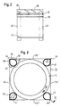
- Figure 2 is a side view of a container according to a second embodiment,
- Figure 3 is a plan view of the container according to Figures 1 and 2,
- Figure 4 is a longitudinal section view of the upper end of one corner of the container along line IV-IV in Figure 3,
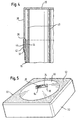
- Figure 5 is a perspective view of the lid according to one embodiment used with the container according to the invention,
- Figure 6 is a side view of two containers according to the invention stacked one on top of another,
- Figure 7 is a longitudinal section view through central cores arranged within the container according to the invention which are stacked one onto another,
- Figure 8 is a plan view of a container according to the invention showing on each corner stabilising elements according to the different embodiments,
- Figure 9 is a plan view of a container with the stabilising elements of Figure 8 featured as hollow elements,
- Figure 10 is a plan view of a container according to a further embodiment with stabilising elements of different design arranged in each corner,
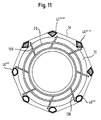
- Figure 11 is a plan view of a container according to a further embodiment showing stabilising elements of different design in the comer,
- Figures 12a to Figure 12c are perspective side views of different stabilising elements which can be used with a container according to the present invention, and
- Figures 13 and 14 are plan views of containers having an inner wall for increased stability.
- A container for accommodating of welding wire W according to a first embodiment is shown in Figure 1. The container comprises as main components a box-
like body 10 having a bottom 12 which is supported by a pallet 14 defining a lower part of the bottom. The box-like body further has aside wall 16 which is, in the circumferential direction, closed. The bottom and the side wall are, according to the preferred embodiment, made from cardboard. The pallet 14 is of wood. - A
coil 18 of welding wire W is arranged within the container. Aretainer 20, which is ring-shaped, sits on the welding wire W for downholding the wire coil strands. The upper end of the wire extends upwards from theretainer 20 to alid 22 which closes the container and which is placed on top of the box-like body 16 which latter having an open upper side. Thelid 22 has a central wire-exitinghole 24 through which thewire end 24 extends even in the shipping state which is shown in Figure 1. The wire-exiting hole is defined by a reinforcement ring in the form of arivet 26 which is attached to the lid 22 (see also Fig. 5). - The
lid 22 is of transparent material only (with the exception of the rivet 26) and is made from one piece. According to the preferred embodiment, the lid is of plastics, e.g. PE or PP, which has a thickness of only 1 or 2 mm and is moulded, e.g. injection-moulded, in one-piece or stamped and pressed by use of heated moulds. - The lid has an upper plate-shaped
portion 28 and a ring-shapedcollar 30 which extends downwardly from the plate-shapedportion 28 and which engages around the outer periphery 32 (see Figure 4) of theupper edge 34 of theside wall 16. - The
upper end 36 of theside wall 16 may extend up to the plate-shapedportion 28 to contact it. - However, according to one preferred embodiment, the
upper end 36 is distanced from the plate-shapedportion 28. In this embodiment, thelid 28 lies on stabilisingelements 40 which are part of the body and extend upwardly from the bottom 12 to thelid 28 protruding over theupper end 36 of thesidewall 16 to the plate-shape portion 28. The stabilisingelements 40 are made from cardboard and are hollow. - The
collar 30 extends downwardly to theupper end 36 of theside wall 16 and overlaps theupper edge 34 and is fixed to the side wall at itsupper edge 34. For fixing thelid 22 to theside wall 16, an adhesive, preferably transparent tape ortight plastic foil 42 is wrapped around thelower end 44 of the ring-shapedcollar 30 and the outer periphery of theupper edge 34 of theside wall 16. The adhesive tape or foil 42 further acts as a seal preventing moisture from entering into the container. - As the
lid 28 is all transparent, a visual inspection of the content of the container can be made from above (through the plate-shaped portion) or from the side (through the collar 30). The visual inspection from the side through the transparent collar thus allows visual inspection of the containers' interior even if the containers are stacked one on top of another during storage or transportation (see Figure 6). - The container allows shipping and later fitting of a wire conduit device of a welding machine and withdrawal of the wire without opening of the container. For shipping purposes, the lid and the body are of such shape and such stability that containers of the same design can be stacked onto each other when filled with the wire so that the bottom of the upper container is placed on the lid of the lower container as can be seen in Figure 6. The horizontal braces 60 of the pallet 14 which define part of the body contact the lid close to its radial outer edge where the stabilising
elements 40 are arranged. Therefore, the load of the upper container is transferred through thelid 22 into the stabilisingelements 40 and, finally, to the ground. - A further reason why the container is immediately ready for use is that in the shipping condition the
wire end 24 already extends through the wire-exitinghole 64. - The
wire end 24 is attached to the lid by anadhesive tape 66 which further sealingly closes the wire-exiting hole so as to prevent moisture from entering into the container. Theadhesive tape 66 is only to be removed, and a fitting 68 of a conduit device is to be attached to the lid. Therivet 26 shown in Figure 5 may help to securely attach the fitting 68 to thelid 22. - According to the embodiment shown in Figure 2, the upper plate-shaped
portion 28 of the lid is completely plain. - However, according to the embodiment shown in Figure 1, the upper plate-shaped
portion 28 has a convex- or dome-shapedhollow centre portion 50 and a flatouter portion 52 which is ring-shaped and which surrounds thecentre portion 50. - The flat
outer portion 52 may have a rough finish surface as seen in the embodiment according to Figure 5 whereas the protrudingcentre portion 50 is completely transparent. Even if theouter portion 52 is rough, this portion is at least translucent allowing more light to enter the interior of the container. - The lid has a slightly conical shape by the
collar 30 slightly tapering in the upward direction. This shape facilitates installation of the lid onto the body and allows stacking of a number of lids one into another and, thus, an easier transport for recycling or disposal. As the lid is of plastics which can be recycled and of one material only, the recycling or disposal is further facilitated. - For increasing the stability and rigidity of the
lid 20, the lid may haveribs 98, for example on the lower side of the plate-shapedportion 28. Theribs 98 are formed on the plate-shaped 28 portion and are formed when moulding or forming the lid. - According to the preferred embodiments of Figs. 1 and 2, the body has a polygonal, more precisely a square shape as can be seen from Figure 3. Elongated stabilising
elements 40 extending from the bottom 12 along the corresponding corner upwards to protrude over the upper end of the side wall are arranged at eachcomer 80 of thebody 10. The stabilising elements have a roundedinner portion 82 in the form of a segment of a circle facing the interior of the container and acorner contact portion 84 which is defined by twoflat sections 86 extending in an angle α of 90° with respect to each other and facing the adjacent side wall. The angle α corresponds to the angle of the comers 80 (some difference may be acceptable) betweenadjacent panels side wall 16 so that theside wall 16 is contacted by thecorner portion 84 over a large area. The stabilisingelements 40 prevent bulging and deformation of the complete container caused by the pressure of thewire coil 70 acting in the radial outward direction. The stabilisingelements 40 take up the pressure of thewire coil 70 to transmit it directly into thecorners 80 so that thepanels 116 to 116''' are not deformed. For that reason, the corner portion of each element tapers toward the outer edge of the element which edge contacts the adjacent corner. Further, the corner portion and the inner portion define an integral piece. - To achieve a high stability of the stabilising
elements 40, theinner portion 82 defines a continuous inner wall, i.e. there is no elongated vertical slit provided in theinner portion 84. Rather, the inner portion is one piece. - In all embodiments shown in the drawings, the
comer portion 84 continues in one piece with theinner portion 82. The embodiment according to Figure 3 shows (like most of the other embodiments) stabilisingelements 40 having a circumferentially closedouter shell portion 89 or outer wall defined by the outer surface of thecomer portion 84 and theinner portion 82 which continue in one piece with each other. Due to the closedouter shell portion 89, the stability of theentire stabilising elements 40 and not only of theinner portion 82 is increased with respect to a cylindrical stabilising element which has a vertical slit or is open to its interior. With those embodiments comprising hollow stabilising elements, theouter shell portion 89 is always defined by a circumferentially closed, ring shaped outer wall. - It is to be emphasized that stabilising
elements 40 do not have to be arranged in eachcorner 80. Especially if there are more than four comers, it is sufficient to have somecorners 80 provided with stabilisingelements 40. In order to allow double-stacking, at least three, preferably fourcomers 80 should have stabilisingelements 40. Apositioning element 41, preferably of wood and of only a few centimeters height, is nailed onto the bottom 12 and protrudes into the hollow stabilisingelement 40 to avoid any sideward displacement of the associated stabilisingelement 40 which is only stacked onto the positioning element 41 (see Figs. 2 and 3). Usually, each stabilisingelement 40 has its associatedpositioning element 41. - The deformation of the container due to the load of the wire W can be further reduced by additional support means in the form of a close ring extending along the periphery of the body. This support means is, for example, a
tape 90 wrapped around the outer periphery of the body (see Figure 4). The support means is, according to a preferred embodiment, arranged close to the upper end of theside wall 16. - A
central core 92 within thecontainer 10 which is placed on the bottom extends upwardly through the middle of the wire coil. Thecore 92 has a frusto-conical or pyramidal shape and is of cardboard or plastics. Thecentral core 92 is further hollow and of such shape that a plurality of the cores are to be stacked one into another for facilitating transportation for recycling or disposal (see Figure 7). Thecentral core 92 is placed on the bottom without being fixed thereto. Due to the tapered shape of the core 92 the wire W comes out of the container at a smooth angle, gently touching on the whole length of thecore 92. - In the embodiments according to Figures 8 through 14, different designs of the stabilising
elements 40 are shown. - Figures 8 and 9 show different shapes of stabilising elements 40' to 40"" wherein the stabilising elements 40' to 40"" according to Figure 8 are sturdy, i.e. full parts, and the stabilising elements 40' to 40"" according to Figure 9 are parts with a corresponding
outer shell portion 89 but are hollow. Each stabilising element 40' to 40"" has acomer portion 84 adapted to the shape of theadjacent comer 80 so that thecorner portion 84 contacts theadjacent side wall 16 over its entire surface. Each stabilising element 40' to 40"" has aninner portion 82 which bulges or protrudes towards the interior of the container. Common to all stabilising elements 40' to 40"" is that the elements are of one piece, only, and can be made from cardboard or plastics, metal or wood. - The stabilising elements 40' have a square cross-sectional shape, two sides defining the
corner portion 84 and two sides theinner portion 82. Theinner portion 82 bulges or protrudes inwardly with respect to a line L through the circumferential ends of contact of the centre portion with theside wall 16. -
Stabilising elements 40" have a differentinner portion 82 in the form of a half-circle with anindentation 130. - Stabilising element 40''' has an
inner portion 82 with two parallel sides protruding towards a tip for contacting thewire coil 70. - Stabilising
element 40"" has a shape similar to the shape shown in Figure 3 but is of somewhat more compact design as theinner portion 84 is a half-circle whereas the embodiment according to Figure 3 has a rounded inner portion extending over more than 180°. - The embodiments of the stabilising elements 40' to 40''' of Fig. 10 correspond to those shown in Figure 9. Stabilising element 40''''' is similar to element 40' but has a stabilising
rib 132 extending from thecorner 80 towards theinner edge 134 contacting thewire coil 70. This allows a linear force transmission from theinner edge 134 to thecorner 80. - Also shown in Figure 10 is a
retainer 20 made from wire. Outwardly protrudingwire pieces 136 are provided for guiding theretainer 20 in the vertical direction and to avoid a circumferential displacement by engaging the stabilising elements 40' to 40"' and 40"". Theindentation 130 accommodates onewire piece 136 to form a linear guide. - The embodiment according to Figure 11 has an
octagonal sidewall 16 withdifferent stabilising elements 40"" and 40""" wherein the stabilisingelements 40"" are hollow and the stabilisingelements 40""" are sturdy parts, e.g. having a foamed core. - The stabilising
element 40"" is also shown in Figure 12a. - Figure 12b shows a stabilising element 40''''''' in the form of a screen made from wire. Seen from the top, the
inner portion 82 defines a continuous inner wall and theouter shell portion 89 is circumferentially closed. - The stabilising
element 140 according to Figure 12c is of different design as it has the shape of an arrow seen from the top. Theinner portion 82 is a rib which protrudes like a bisecting line of an angle between thelegs 142 defining thecomer portions 84. In this embodiment, thecorner portion 84 tappers towards anouter edge 144 contacting the adjacent corner. Acorner portion 84 and theinner portion 82 define an integral piece so that the force of the wire coil is taken up byedge 44 to be transmitted via the rib-likeinner portion 82 immediately into theadjacent corner 80. - The embodiments according to Figures 13 and 14 comprise an
inner wall inner wall 160 is a circular cylinder, and theinner wall 162 which is also circumferentially closed has an octagonal shape. Bothinner walls wire coil 70, contact the wire coil by their inner sides and contact a stabilisingelement inner walls element corners 80 have adjacent stabilising elements. Theinner walls
Claims (39)
- A container for welding wire, comprisingsaid stabilising elements (40; 40' - 40'''''''; 240; 340) extending upwardly from said bottom (12) and having an outer shell portion comprising a corner portion (84) facing said adjacent side wall (16) and an inner portion (82) facing an interior of said container for housing welding wire (W),a box-like body (10) having a bottom (12) and a side wall (16),
said side wall (16) having a polygonal cross section with corners (80),stabilising elements (40; 40' - 40'''''''; 240; 340) arranged at at least some of said corners (80),
said comer portion (84) having a shape adapted to the shape of said adjacent corner (80), and
said inner portion (82) defining a continuous inner wall. - The container for welding wire, particularly according to claim 1, comprisingsaid stabilising elements (40; 40' - 40'''''''; 140; 240; 340) extending upwardly from said bottom (12) and having an outer shell portion comprising a corner portion (84) facing said adjacent side wall (16) and an inner portion (82) facing an interior of said container for housing welding wire (W),a box-like body (10) having a bottom (12) and a side wall (16),
said side wall (16) having a polygonal cross section with corners (80),stabilising elements (40; 40' - 40'''''''; 140; 240; 340) arranged at at least some of said corners (80),
said corner portion (84) tapering towards an outer edge contacting said adjacent corner (80), and
said corner portion (84) and said inner portion (82) defining an integral piece. - The container according to claim 2, wherein said inner portion (82) defines a continuous inner wall.
- The container according to any of the preceding claims, wherein said corner portion (84) continues in one piece with said inner portion (82) to have a circumferentially closed outer shell portion (89).
- The container according to any of the preceding claims, wherein said corner portion (84) contacts said adjacent comer (80) over a large area.
- The container according to any of the preceding claims, wherein an angle (α) defining said corner portion (84) and an angle defining said adjacent corner (40; 40' - 40'''''''; 240; 340) substantially correspond to each other.
- The container according to any of the preceding claims, wherein said inner portion (82) bulges towards said interior of said container.
- The container according to claim 7, wherein said inner portion (82) is rounded.
- The container according to claim 8, wherein said inner portion (82) is a section of a cylinder.
- The container according to claim 7, wherein said inner portion (82) is cornered.
- The container according to any of the preceding claims, wherein said stabilising element (40; 40' - 40'''''''; 240; 340) is hollow.
- The container according to any of the preceding claims, wherein said stabilising element (40; 40' - 40'''''''; 240; 340) is made from cardboard, plastics, wood or from metal.
- The container according to any of the preceding claims, wherein said stabilising element (40''''''') is a screen made from a wire which screen defines said outer shell portion.
- The container according to any of the preceding claims, wherein said stabilising element (40; 40' - 40'''''''; 240; 340) is of one piece only and is hollow.
- The container according to any one of claims 1 to 13, wherein said stabilising element (40' - 40''''; 40'''''') is a sturdy part.
- The container according to any of the preceding claims, wherein said side wall (16) has a rectangular shape and wherein said corner portion (84) is defined by two flat wall sections extending in an angle of 90° with respect to each other.
- The container according to any of the preceding claims, wherein said container is filled with welding wire (W), wherein a retainer (20) sitting on said welding wire (W) for downholding wire coil strands is provided.
- The container according to claim 17, wherein said retainer (20) has sidewardly extending protrusions which are guided by said stabilising elements (40' -40'''''').
- The container according to any of the preceding claims, wherein an inner wall arranged between said wire (W) and said stabilising elements is provided, said inner wall circumscribing said wire (W) and, on its inner side, contacting said wire (W) and, on its outer side, contacting said stabilising elements (240; 340).
- The container according to claim 19, wherein said inner wall has a circumferentially closed cross-section.
- The container according to claim 20, wherein said inner wall has one of a cylindrical and polygonal cross-section.
- The container according to any of the preceding claims, wherein said container being filled with welding wire (W), and wherein said container is of such shape and such stability that containers of the same design and filled with welding wire (W) can be double-stacked with a bottom (12) of an upper container being placed on a lower container.
- The container according to any of the preceding claims, wherein said stabilising elements (40; 40' - 40'''''''; 240; 340) protrude over an upper end (36) of said side wall (16).
- The container according to any of the preceding claims, further comprising a lid (22) at a top of the body (10) closing said container, said lid (22) consisting of transparent material allowing a visual inspection of said interior of said container.
- The container according to claim 24, wherein said lid (22) is of plastics and one of moulded and stamped in one-piece.
- The container according to claim 24 or 25, wherein said lid (22) has an upper plate-shaped portion (28) and a ring-shaped collar (30) extending downwardly from said plate-shaped portion (28) and engaging around an outer periphery of an upper edge (34) of said side wall (16).
- The container according to claims 23 and 26, wherein said collar (30) extends downwardly to an upper end (36) of said side wall (16) to be fixed thereto.
- The container according to any of claims 24 to 27, wherein a seal is provided between said lid (22) and said body (10) preventing moisture from entering into said container.
- The container according to claim 28, wherein said seal is one of an adhesive tape and a tight plastic foil (42) which further attaches said lid (22) to said body (10).
- The container according to any of claims 24 to 29, wherein, in a shipping state of said container in which said container is filled with welding wire (W), a wire end (24) extends outwardly from said container through a wire-exiting hole (26) in said lid (22) and is attached to said container.
- The container according to claim 30, wherein, in a shipping state of said container, said wire end (24) extending through said wire-exiting hole (26) is attached to said lid (22) by one of an adhesive tape (66) and a plastic foil which further sealingly closes said wire-exiting hole (26) and prevents moisture from entering into said container.
- The container according to any of claims 24 to 31, wherein said lid (22) has an upper plate-shaped portion (28) with an upwardly protruding centre portion (50).
- The container according to claim 32, wherein said plate-shaped portion (28) has a flat outer portion surrounding said centre portion (50).
- The container according to any of the preceding claims, wherein said bottom (12) (12) comprises a pallet (14).
- The container according to any of the preceding claims, wherein said container is filled with welding wire (W) and wherein a support means in the form of a close ring (90) extending along a periphery of said body (10) is provided to avoid deformation of said body (10) by radial pressure of said wire (W).
- The container according to claim 35, wherein said support means is a tape wrapped around an outer periphery of said body (10).
- The container according to any of the preceding claims, wherein said container is filled with welding wire (W) and wherein a central core (92) arranged within said container, placed on said bottom (12) and extending upwardly through a middle of a wire coil is provided, said core (92) tapering in an upward direction.
- The container according to claim 37, wherein said core (92) has one of a frusto-conical and a pyramidal shape.
- The container according to claim 37 or 38, wherein said central core (92) is hollow and of such shape that a plurality of such cores (92) are able to be stacked one into another and wherein said central core (92) is placed on said bottom (12) without being fixed thereto.
Priority Applications (1)
| Application Number | Priority Date | Filing Date | Title |
|---|---|---|---|
| EP05023898A EP1621503A1 (en) | 2001-09-19 | 2002-09-19 | Container for welding wire |
Applications Claiming Priority (2)
| Application Number | Priority Date | Filing Date | Title |
|---|---|---|---|
| IT2001TO000894A ITTO20010894A1 (en) | 2001-09-19 | 2001-09-19 | CONTAINER OF A WELDING WIRE. |
| ITTO20010894 | 2001-09-19 |
Related Child Applications (1)
| Application Number | Title | Priority Date | Filing Date |
|---|---|---|---|
| EP05023898A Division EP1621503A1 (en) | 2001-09-19 | 2002-09-19 | Container for welding wire |
Publications (3)
| Publication Number | Publication Date |
|---|---|
| EP1295813A2 true EP1295813A2 (en) | 2003-03-26 |
| EP1295813A3 EP1295813A3 (en) | 2004-03-17 |
| EP1295813B1 EP1295813B1 (en) | 2009-12-16 |
Family
ID=11459207
Family Applications (2)
| Application Number | Title | Priority Date | Filing Date |
|---|---|---|---|
| EP02021262A Expired - Lifetime EP1295813B1 (en) | 2001-09-19 | 2002-09-19 | Container for welding wire |
| EP05023898A Withdrawn EP1621503A1 (en) | 2001-09-19 | 2002-09-19 | Container for welding wire |
Family Applications After (1)
| Application Number | Title | Priority Date | Filing Date |
|---|---|---|---|
| EP05023898A Withdrawn EP1621503A1 (en) | 2001-09-19 | 2002-09-19 | Container for welding wire |
Country Status (8)
| Country | Link |
|---|---|
| US (1) | US6938767B2 (en) |
| EP (2) | EP1295813B1 (en) |
| AT (1) | ATE452080T1 (en) |
| CA (1) | CA2403067C (en) |
| DE (1) | DE60234744D1 (en) |
| DK (1) | DK1295813T3 (en) |
| ES (1) | ES2338299T3 (en) |
| IT (1) | ITTO20010894A1 (en) |
Cited By (23)
| Publication number | Priority date | Publication date | Assignee | Title |
|---|---|---|---|---|
| EP1357059A2 (en) * | 2002-04-24 | 2003-10-29 | ISAF S.p.A. | Welding wire coil container providable with a device for connecting thereto a sheath for feeding the wire to a welding machine |
| EP1693140A1 (en) | 2005-02-17 | 2006-08-23 | La Soudure Autogene Francaise | Container for welding-wire with sloping internal wall. |
| EP1693139A1 (en) | 2005-02-17 | 2006-08-23 | La Soudure Autogene Francaise | Welding-wire packing container with internal winding retention system. |
| FR2910445A1 (en) * | 2006-12-20 | 2008-06-27 | Air Liquide | Consumable welding product e.g. wire, conditioning assembly for e.g. truck, has container containing consumable welding product and surmounted by cap, which is made of deformable material, which deforms under effect of force applied on cap |
| US7410111B2 (en) | 2006-06-16 | 2008-08-12 | Lincoln Global, Inc. | Guide ring for coiled wire |
| US7690593B2 (en) | 2007-07-09 | 2010-04-06 | Lincoln Global, Inc. | Welding wire guide ring |
| US7721985B2 (en) | 2007-07-09 | 2010-05-25 | Lincoln Global, Inc. | Welding wire guide ring |
| US7938352B2 (en) | 2009-03-10 | 2011-05-10 | Lincoln Global, Inc. | Wire dispensing apparatus for packaged wire |
| US7950523B2 (en) | 2006-03-30 | 2011-05-31 | Sidergas Spa | Retainer for a welding wire coil |
| DE202011108769U1 (en) | 2011-12-07 | 2012-01-24 | Mig Weld Gmbh International | Unwinding device for wire barrels |
| US8127923B2 (en) | 2009-11-13 | 2012-03-06 | Sidergas Spa | Container for welding wire |
| EP2447199A1 (en) | 2010-11-02 | 2012-05-02 | SIDERGAS SpA | Retainer for welding wire container, having fingers and half-moon shaped holding tabs |
| US8393467B2 (en) | 2009-08-21 | 2013-03-12 | Sidergas Spa | Retainer for welding wire container, having fingers and half-moon shaped holding tabs |
| EP3309097A1 (en) * | 2016-10-17 | 2018-04-18 | SIDERGAS SpA | Welding wire container |
| US9975728B2 (en) | 2015-09-10 | 2018-05-22 | Sidergas Spa | Wire container lid, wire container and wire feeding system |
| US10010962B1 (en) | 2014-09-09 | 2018-07-03 | Awds Technologies Srl | Module and system for controlling and recording welding data, and welding wire feeder |
| US10294065B2 (en) | 2013-06-06 | 2019-05-21 | Sidergas Spa | Retainer for a welding wire container and welding wire container |
| US10343231B2 (en) | 2014-05-28 | 2019-07-09 | Awds Technologies Srl | Wire feeding system |
| US10350696B2 (en) | 2015-04-06 | 2019-07-16 | Awds Technologies Srl | Wire feed system and method of controlling feed of welding wire |
| EP3715270A3 (en) * | 2019-03-26 | 2020-11-18 | Lincoln Global, Inc. | Method and apparatus for packaging wire in a storage container |
| EP3356243B1 (en) * | 2015-10-01 | 2021-11-10 | AlzChem Trostberg GmbH | Storage and transport container for cored wires |
| US11174121B2 (en) | 2020-01-20 | 2021-11-16 | Awds Technologies Srl | Device for imparting a torsional force onto a wire |
| US11278981B2 (en) | 2020-01-20 | 2022-03-22 | Awds Technologies Srl | Device for imparting a torsional force onto a wire |
Families Citing this family (27)
| Publication number | Priority date | Publication date | Assignee | Title |
|---|---|---|---|---|
| US7191968B2 (en) * | 2004-05-19 | 2007-03-20 | National Standard Company | System for handling welding wire and method of handling welding wire using the system |
| DE102005018566A1 (en) * | 2005-04-21 | 2006-10-26 | Sidergas Spa | Cover for a welding wire container |
| ITTO20050591A1 (en) * | 2005-08-29 | 2007-02-28 | Sidergas Srl | REINFORCEMENT ELEMENT FOR A WELDING CONTAINER |
| US20070051716A1 (en) * | 2005-09-06 | 2007-03-08 | Lincoln Global, Inc. | Process for manufacturing packaged cored welding electrode |
| KR100853528B1 (en) * | 2006-12-13 | 2008-08-21 | 고려용접봉 주식회사 | pail-pack for welding wire |
| US7905439B2 (en) | 2007-08-30 | 2011-03-15 | Lincoln Global, Inc. | Apparatus and method for tapered core drum package payoff |
| US7866586B2 (en) | 2007-08-30 | 2011-01-11 | Lincoln Global, Inc. | Wire guide insert and method for drum package payoff |
| ES2414807T3 (en) | 2008-05-27 | 2013-07-22 | Awds Technologies Srl | Wire guiding system |
| ES2391485T3 (en) | 2008-10-07 | 2012-11-27 | Sidergas Spa | Cap for welding wire container |
| US8235210B2 (en) * | 2009-04-27 | 2012-08-07 | Lincoln Global, Inc. | Welding wire container cover and container containing same |
| CA2767884A1 (en) | 2009-07-20 | 2011-01-27 | Awds Technologies Srl | A wire guiding liner, an particular a welding wire liner, with biasing means between articulated guiding bodies |
| US8235211B2 (en) | 2009-08-21 | 2012-08-07 | Sidergas Spa | Retainer for welding wire container, having fingers and half-moon shaped holding tabs |
| EP2353765A1 (en) * | 2010-01-27 | 2011-08-10 | Oerlikon Schweisstechnik GmbH | Container for welding wire with reinforcing strips in its peripheral wall |
| US8389901B1 (en) | 2010-05-27 | 2013-03-05 | Awds Technologies Srl | Welding wire guiding liner |
| US8381906B2 (en) | 2011-05-23 | 2013-02-26 | Linclon Global, Inc. | Bulk wire dampening apparatus and method |
| US20130082132A1 (en) * | 2011-10-04 | 2013-04-04 | Ryan William Gaul | Work storage containers |
| US8752782B2 (en) | 2011-11-22 | 2014-06-17 | Lincoln Global, Inc. | Wire retaining ring for endless bulk mig wire boxes |
| US8967520B2 (en) | 2011-11-22 | 2015-03-03 | Lincoln Global, Inc. | Wire retaining ring for a welding system |
| US8882018B2 (en) | 2011-12-19 | 2014-11-11 | Sidergas Spa | Retainer for welding wire container and welding wire container with retainer |
| CN102582644A (en) * | 2012-02-23 | 2012-07-18 | 蒋恩泉 | Vertically-loaded coil steel seat frame |
| US9278827B2 (en) * | 2012-08-22 | 2016-03-08 | Sonoco Development, Inc. | Reel with built in pallet |
| US20140061361A1 (en) * | 2012-09-04 | 2014-03-06 | William R. Marble | String dispenser for dispensing string wound on a hollow core |
| BR112015010830B1 (en) | 2012-11-12 | 2021-09-14 | Southwire Company, Llc | CABLE PACKAGE |
| JP6275217B1 (en) * | 2016-09-08 | 2018-02-07 | 日鉄住金物流株式会社 | Coil loading method and coil loading structure on container |
| USD991299S1 (en) | 2021-04-30 | 2023-07-04 | Esab Ab | Hood for a welding consumable container |
| USD998664S1 (en) | 2021-04-30 | 2023-09-12 | Esab Ab | Welding consumable container |
| USD998665S1 (en) | 2021-04-30 | 2023-09-12 | Esab Ab | Welding consumable container |
Citations (8)
| Publication number | Priority date | Publication date | Assignee | Title |
|---|---|---|---|---|
| US3244347A (en) * | 1964-02-20 | 1966-04-05 | Mead Corp | Corner post construction |
| US3648920A (en) * | 1968-11-20 | 1972-03-14 | Clevepak Corp | Tubular member |
| FR2267255A1 (en) * | 1974-04-10 | 1975-11-07 | Lafarge Emballage | Case for bulk liquid or powdered products - has polygonal section sleeve and stiffeners in square section container |
| US3939978A (en) * | 1974-07-23 | 1976-02-24 | Ppg Industries, Inc. | Flat glass shipping container |
| GB2264482A (en) * | 1992-02-28 | 1993-09-01 | M Y Humberside Packaging Limit | Stackable container |
| EP0665166A1 (en) * | 1994-01-27 | 1995-08-02 | Mitchell Packaging Limited | Container with support posts |
| EP1057751A1 (en) * | 1999-05-31 | 2000-12-06 | C.I.F.E. S.p.A. | Cardboard box for containing and dispensing wire |
| EP1275595A2 (en) * | 2001-07-13 | 2003-01-15 | Lincoln Global, Inc. | Container for welding wire |
Family Cites Families (15)
| Publication number | Priority date | Publication date | Assignee | Title |
|---|---|---|---|---|
| US2943732A (en) * | 1956-04-09 | 1960-07-05 | Coulter & Mckenzie Machine Co | Package and container forming part thereof |
| US4161248A (en) | 1977-10-17 | 1979-07-17 | Universal Wire & Cable Co. Ltd. | Container for wire spool |
| US4392606A (en) * | 1981-12-17 | 1983-07-12 | Westvaco Corporation | Pre-banded bulk pack container |
| US4451014A (en) | 1982-08-11 | 1984-05-29 | Mossberg Industries, Inc. | Wire storing and dereeling apparatus |
| US5201419A (en) * | 1992-02-21 | 1993-04-13 | Laclede Chain Manufacturing Company | Chain container |
| AT397778B (en) | 1992-07-29 | 1994-06-27 | Boehler Schweisstechnik | CONTAINER FOR WELDING WIRE |
| IT231566Y1 (en) | 1993-02-23 | 1999-08-04 | Sidergas Srl | CONTAINER FOR PACKAGING AND UNWINDING A HANK OF METAL WIRE |
| US5553810A (en) * | 1994-02-23 | 1996-09-10 | The Lincoln Electric Company | Covers for welding wire reels |
| US5738209A (en) | 1996-12-23 | 1998-04-14 | General Motors Corporation | Cable storage container |
| AU3365097A (en) | 1997-05-20 | 1998-12-11 | Esab Ab | Container for packaging and unwinding a coil of welding wire |
| US5988370A (en) * | 1997-06-23 | 1999-11-23 | Roemer; Donald A. | Corrugated fibreboard container with at least one hinged side and blanks for assembling said container |
| US5921391A (en) * | 1997-11-26 | 1999-07-13 | Stone Container Corporation | Container for storing and transporting wire, cord and the like |
| US6109554A (en) * | 1998-09-21 | 2000-08-29 | Windings, Inc. | Combined fiber containers and payout tubes and plastic payout tubes |
| JP2001138052A (en) * | 1999-11-19 | 2001-05-22 | Nippon Steel Weld Prod & Eng Co Ltd | Loading body for welding wire |
| US6648141B2 (en) * | 2001-09-04 | 2003-11-18 | Lincoln Global, Inc. | Packaging for containing and dispensing large quantities of wire |
-
2001
- 2001-09-19 IT IT2001TO000894A patent/ITTO20010894A1/en unknown
-
2002
- 2002-09-12 US US10/242,029 patent/US6938767B2/en not_active Expired - Lifetime
- 2002-09-13 CA CA2403067A patent/CA2403067C/en not_active Expired - Lifetime
- 2002-09-19 ES ES02021262T patent/ES2338299T3/en not_active Expired - Lifetime
- 2002-09-19 AT AT02021262T patent/ATE452080T1/en active
- 2002-09-19 EP EP02021262A patent/EP1295813B1/en not_active Expired - Lifetime
- 2002-09-19 DK DK02021262.7T patent/DK1295813T3/en active
- 2002-09-19 DE DE60234744T patent/DE60234744D1/en not_active Expired - Lifetime
- 2002-09-19 EP EP05023898A patent/EP1621503A1/en not_active Withdrawn
Patent Citations (8)
| Publication number | Priority date | Publication date | Assignee | Title |
|---|---|---|---|---|
| US3244347A (en) * | 1964-02-20 | 1966-04-05 | Mead Corp | Corner post construction |
| US3648920A (en) * | 1968-11-20 | 1972-03-14 | Clevepak Corp | Tubular member |
| FR2267255A1 (en) * | 1974-04-10 | 1975-11-07 | Lafarge Emballage | Case for bulk liquid or powdered products - has polygonal section sleeve and stiffeners in square section container |
| US3939978A (en) * | 1974-07-23 | 1976-02-24 | Ppg Industries, Inc. | Flat glass shipping container |
| GB2264482A (en) * | 1992-02-28 | 1993-09-01 | M Y Humberside Packaging Limit | Stackable container |
| EP0665166A1 (en) * | 1994-01-27 | 1995-08-02 | Mitchell Packaging Limited | Container with support posts |
| EP1057751A1 (en) * | 1999-05-31 | 2000-12-06 | C.I.F.E. S.p.A. | Cardboard box for containing and dispensing wire |
| EP1275595A2 (en) * | 2001-07-13 | 2003-01-15 | Lincoln Global, Inc. | Container for welding wire |
Cited By (30)
| Publication number | Priority date | Publication date | Assignee | Title |
|---|---|---|---|---|
| EP1357059A2 (en) * | 2002-04-24 | 2003-10-29 | ISAF S.p.A. | Welding wire coil container providable with a device for connecting thereto a sheath for feeding the wire to a welding machine |
| EP1357059A3 (en) * | 2002-04-24 | 2004-02-11 | ISAF S.p.A. | Welding wire coil container providable with a device for connecting thereto a sheath for feeding the wire to a welding machine |
| EP1693140A1 (en) | 2005-02-17 | 2006-08-23 | La Soudure Autogene Francaise | Container for welding-wire with sloping internal wall. |
| EP1693139A1 (en) | 2005-02-17 | 2006-08-23 | La Soudure Autogene Francaise | Welding-wire packing container with internal winding retention system. |
| US7950523B2 (en) | 2006-03-30 | 2011-05-31 | Sidergas Spa | Retainer for a welding wire coil |
| US7410111B2 (en) | 2006-06-16 | 2008-08-12 | Lincoln Global, Inc. | Guide ring for coiled wire |
| FR2910445A1 (en) * | 2006-12-20 | 2008-06-27 | Air Liquide | Consumable welding product e.g. wire, conditioning assembly for e.g. truck, has container containing consumable welding product and surmounted by cap, which is made of deformable material, which deforms under effect of force applied on cap |
| US7690593B2 (en) | 2007-07-09 | 2010-04-06 | Lincoln Global, Inc. | Welding wire guide ring |
| US7721985B2 (en) | 2007-07-09 | 2010-05-25 | Lincoln Global, Inc. | Welding wire guide ring |
| US8042757B2 (en) | 2007-07-09 | 2011-10-25 | Lincoln Global, Inc. | Welding wire guide ring |
| US7938352B2 (en) | 2009-03-10 | 2011-05-10 | Lincoln Global, Inc. | Wire dispensing apparatus for packaged wire |
| US8794561B2 (en) | 2009-03-10 | 2014-08-05 | Lincoln Global, Inc. | Wire dispensing apparatus for packaged wire |
| US8393467B2 (en) | 2009-08-21 | 2013-03-12 | Sidergas Spa | Retainer for welding wire container, having fingers and half-moon shaped holding tabs |
| US8127923B2 (en) | 2009-11-13 | 2012-03-06 | Sidergas Spa | Container for welding wire |
| EP2447199A1 (en) | 2010-11-02 | 2012-05-02 | SIDERGAS SpA | Retainer for welding wire container, having fingers and half-moon shaped holding tabs |
| DE202011108769U1 (en) | 2011-12-07 | 2012-01-24 | Mig Weld Gmbh International | Unwinding device for wire barrels |
| US10294065B2 (en) | 2013-06-06 | 2019-05-21 | Sidergas Spa | Retainer for a welding wire container and welding wire container |
| US10343231B2 (en) | 2014-05-28 | 2019-07-09 | Awds Technologies Srl | Wire feeding system |
| US10010962B1 (en) | 2014-09-09 | 2018-07-03 | Awds Technologies Srl | Module and system for controlling and recording welding data, and welding wire feeder |
| US10350696B2 (en) | 2015-04-06 | 2019-07-16 | Awds Technologies Srl | Wire feed system and method of controlling feed of welding wire |
| US9975728B2 (en) | 2015-09-10 | 2018-05-22 | Sidergas Spa | Wire container lid, wire container and wire feeding system |
| EP3356243B1 (en) * | 2015-10-01 | 2021-11-10 | AlzChem Trostberg GmbH | Storage and transport container for cored wires |
| US9950857B1 (en) | 2016-10-17 | 2018-04-24 | Sidergas Spa | Welding wire container |
| EP3309097A1 (en) * | 2016-10-17 | 2018-04-18 | SIDERGAS SpA | Welding wire container |
| EP3715270A3 (en) * | 2019-03-26 | 2020-11-18 | Lincoln Global, Inc. | Method and apparatus for packaging wire in a storage container |
| EP3786084A1 (en) * | 2019-03-26 | 2021-03-03 | Lincoln Global, Inc. | Apparatus, method and storage container |
| US11014735B2 (en) | 2019-03-26 | 2021-05-25 | Lincoln Global, Inc. | Method and apparatus for packaging wire in a storage container |
| US11718466B2 (en) | 2019-03-26 | 2023-08-08 | Lincoln Global, Inc. | Method and apparatus for packaging wire in a storage container |
| US11174121B2 (en) | 2020-01-20 | 2021-11-16 | Awds Technologies Srl | Device for imparting a torsional force onto a wire |
| US11278981B2 (en) | 2020-01-20 | 2022-03-22 | Awds Technologies Srl | Device for imparting a torsional force onto a wire |
Also Published As
| Publication number | Publication date |
|---|---|
| DK1295813T3 (en) | 2010-04-19 |
| EP1295813A3 (en) | 2004-03-17 |
| EP1621503A1 (en) | 2006-02-01 |
| ITTO20010894A1 (en) | 2003-03-19 |
| US20030052030A1 (en) | 2003-03-20 |
| CA2403067A1 (en) | 2003-03-19 |
| DE60234744D1 (en) | 2010-01-28 |
| ITTO20010894A0 (en) | 2001-09-19 |
| ES2338299T3 (en) | 2010-05-06 |
| CA2403067C (en) | 2010-06-15 |
| US6938767B2 (en) | 2005-09-06 |
| EP1295813B1 (en) | 2009-12-16 |
| ATE452080T1 (en) | 2010-01-15 |
Similar Documents
| Publication | Publication Date | Title |
|---|---|---|
| EP1295813B1 (en) | Container for welding wire | |
| US7331457B2 (en) | Cardboard box for containing and dispensing large quantities of wire | |
| US3941301A (en) | Stackable packaging container | |
| US5265753A (en) | Container for flexible bag | |
| US2685385A (en) | Liner for rigid containers having a nozzle for filling and emptying the same | |
| US4296871A (en) | Receptacle with a cover of plastics material | |
| EP0284290B1 (en) | Composite shipping container | |
| US2946494A (en) | Container | |
| JP2676189B2 (en) | Transport and storage containers | |
| JP2013500906A (en) | Nestable stackable containers | |
| US4860894A (en) | Package assembly for glass funnel parts | |
| HU210624B (en) | Plastic pallet | |
| JP6907082B2 (en) | Refill container | |
| US5413220A (en) | Energy attenuating support plates for protecting objects thereon | |
| EP0460739A1 (en) | Package | |
| JPH04327154A (en) | Package for liquid or powder product | |
| JP7369721B2 (en) | Packages with plastic containers with a constant stacking pitch | |
| IT202100018110A1 (en) | Device for containing and dispensing fluid substances | |
| AU4310393A (en) | A base for a transport or liquid container | |
| JPH0320314Y2 (en) | ||
| FI94116C (en) | Method of making a closure lid | |
| EP1925558B1 (en) | Package for storage of food products and method for sealing such a package. | |
| US3053428A (en) | Container for substances and method of filling | |
| JPH0536446U (en) | Roll-shaped photosensitive material core protection member | |
| EP1015333A1 (en) | Transport container and method of manufacture thereof |
Legal Events
| Date | Code | Title | Description |
|---|---|---|---|
| PUAI | Public reference made under article 153(3) epc to a published international application that has entered the european phase |
Free format text: ORIGINAL CODE: 0009012 |
|
| AK | Designated contracting states |
Kind code of ref document: A2 Designated state(s): AT BE BG CH CY CZ DE DK EE ES FI FR GB GR IE IT LI LU MC NL PT SE SK TR Designated state(s): AT BE BG CH CY CZ DE DK EE ES FI FR GB GR IE IT LI LU MC NL PT SE SK TR |
|
| AX | Request for extension of the european patent |
Extension state: AL LT LV MK RO SI |
|
| RIC1 | Information provided on ipc code assigned before grant |
Ipc: 7B 65D 19/20 B Ipc: 7B 65D 85/04 A Ipc: 7B 65D 5/50 B Ipc: 7B 65D 81/05 B |
|
| PUAL | Search report despatched |
Free format text: ORIGINAL CODE: 0009013 |
|
| AK | Designated contracting states |
Kind code of ref document: A3 Designated state(s): AT BE BG CH CY CZ DE DK EE ES FI FR GB GR IE IT LI LU MC NL PT SE SK TR |
|
| AX | Request for extension of the european patent |
Extension state: AL LT LV MK RO SI |
|
| 17P | Request for examination filed |
Effective date: 20040830 |
|
| AKX | Designation fees paid |
Designated state(s): AT BE BG CH CY CZ DE DK EE ES FI FR GB GR IE IT LI LU MC NL PT SE SK TR |
|
| GRAP | Despatch of communication of intention to grant a patent |
Free format text: ORIGINAL CODE: EPIDOSNIGR1 |
|
| GRAS | Grant fee paid |
Free format text: ORIGINAL CODE: EPIDOSNIGR3 |
|
| GRAA | (expected) grant |
Free format text: ORIGINAL CODE: 0009210 |
|
| AK | Designated contracting states |
Kind code of ref document: B1 Designated state(s): AT BE BG CH CY CZ DE DK EE ES FI FR GB GR IE IT LI LU MC NL PT SE SK TR |
|
| REG | Reference to a national code |
Ref country code: GB Ref legal event code: FG4D |
|
| REG | Reference to a national code |
Ref country code: CH Ref legal event code: EP |
|
| REG | Reference to a national code |
Ref country code: IE Ref legal event code: FG4D |
|
| REF | Corresponds to: |
Ref document number: 60234744 Country of ref document: DE Date of ref document: 20100128 Kind code of ref document: P |
|
| REG | Reference to a national code |
Ref country code: CH Ref legal event code: NV Representative=s name: BUGNION S.A. |
|
| REG | Reference to a national code |
Ref country code: SE Ref legal event code: TRGR |
|
| REG | Reference to a national code |
Ref country code: DK Ref legal event code: T3 |
|
| PG25 | Lapsed in a contracting state [announced via postgrant information from national office to epo] |
Ref country code: FI Free format text: LAPSE BECAUSE OF FAILURE TO SUBMIT A TRANSLATION OF THE DESCRIPTION OR TO PAY THE FEE WITHIN THE PRESCRIBED TIME-LIMIT Effective date: 20091216 |
|
| REG | Reference to a national code |
Ref country code: ES Ref legal event code: FG2A Ref document number: 2338299 Country of ref document: ES Kind code of ref document: T3 |
|
| REG | Reference to a national code |
Ref country code: SK Ref legal event code: T3 Ref document number: E 6872 Country of ref document: SK |
|
| PG25 | Lapsed in a contracting state [announced via postgrant information from national office to epo] |
Ref country code: BG Free format text: LAPSE BECAUSE OF FAILURE TO SUBMIT A TRANSLATION OF THE DESCRIPTION OR TO PAY THE FEE WITHIN THE PRESCRIBED TIME-LIMIT Effective date: 20100316 Ref country code: PT Free format text: LAPSE BECAUSE OF FAILURE TO SUBMIT A TRANSLATION OF THE DESCRIPTION OR TO PAY THE FEE WITHIN THE PRESCRIBED TIME-LIMIT Effective date: 20100416 Ref country code: EE Free format text: LAPSE BECAUSE OF FAILURE TO SUBMIT A TRANSLATION OF THE DESCRIPTION OR TO PAY THE FEE WITHIN THE PRESCRIBED TIME-LIMIT Effective date: 20091216 |
|
| PLBE | No opposition filed within time limit |
Free format text: ORIGINAL CODE: 0009261 |
|
| STAA | Information on the status of an ep patent application or granted ep patent |
Free format text: STATUS: NO OPPOSITION FILED WITHIN TIME LIMIT |
|
| PG25 | Lapsed in a contracting state [announced via postgrant information from national office to epo] |
Ref country code: CY Free format text: LAPSE BECAUSE OF FAILURE TO SUBMIT A TRANSLATION OF THE DESCRIPTION OR TO PAY THE FEE WITHIN THE PRESCRIBED TIME-LIMIT Effective date: 20091216 Ref country code: GR Free format text: LAPSE BECAUSE OF FAILURE TO SUBMIT A TRANSLATION OF THE DESCRIPTION OR TO PAY THE FEE WITHIN THE PRESCRIBED TIME-LIMIT Effective date: 20100317 |
|
| PGFP | Annual fee paid to national office [announced via postgrant information from national office to epo] |
Ref country code: IE Payment date: 20100929 Year of fee payment: 9 |
|
| 26N | No opposition filed |
Effective date: 20100917 |
|
| PGFP | Annual fee paid to national office [announced via postgrant information from national office to epo] |
Ref country code: AT Payment date: 20100923 Year of fee payment: 9 |
|
| PGFP | Annual fee paid to national office [announced via postgrant information from national office to epo] |
Ref country code: CH Payment date: 20101014 Year of fee payment: 9 Ref country code: CZ Payment date: 20101214 Year of fee payment: 9 Ref country code: SK Payment date: 20101203 Year of fee payment: 9 |
|
| PG25 | Lapsed in a contracting state [announced via postgrant information from national office to epo] |
Ref country code: MC Free format text: LAPSE BECAUSE OF NON-PAYMENT OF DUE FEES Effective date: 20100930 |
|
| PG25 | Lapsed in a contracting state [announced via postgrant information from national office to epo] |
Ref country code: CZ Free format text: LAPSE BECAUSE OF NON-PAYMENT OF DUE FEES Effective date: 20110919 |
|
| REG | Reference to a national code |
Ref country code: CH Ref legal event code: PL |
|
| REG | Reference to a national code |
Ref country code: SK Ref legal event code: MM4A Ref document number: E 6872 Country of ref document: SK Effective date: 20110919 |
|
| REG | Reference to a national code |
Ref country code: IE Ref legal event code: MM4A |
|
| PG25 | Lapsed in a contracting state [announced via postgrant information from national office to epo] |
Ref country code: IE Free format text: LAPSE BECAUSE OF NON-PAYMENT OF DUE FEES Effective date: 20110919 Ref country code: LI Free format text: LAPSE BECAUSE OF NON-PAYMENT OF DUE FEES Effective date: 20110930 Ref country code: CH Free format text: LAPSE BECAUSE OF NON-PAYMENT OF DUE FEES Effective date: 20110930 Ref country code: SK Free format text: LAPSE BECAUSE OF NON-PAYMENT OF DUE FEES Effective date: 20110919 |
|
| PG25 | Lapsed in a contracting state [announced via postgrant information from national office to epo] |
Ref country code: LU Free format text: LAPSE BECAUSE OF NON-PAYMENT OF DUE FEES Effective date: 20100919 |
|
| PG25 | Lapsed in a contracting state [announced via postgrant information from national office to epo] |
Ref country code: TR Free format text: LAPSE BECAUSE OF FAILURE TO SUBMIT A TRANSLATION OF THE DESCRIPTION OR TO PAY THE FEE WITHIN THE PRESCRIBED TIME-LIMIT Effective date: 20091216 |
|
| REG | Reference to a national code |
Ref country code: AT Ref legal event code: MM01 Ref document number: 452080 Country of ref document: AT Kind code of ref document: T Effective date: 20110919 |
|
| PG25 | Lapsed in a contracting state [announced via postgrant information from national office to epo] |
Ref country code: AT Free format text: LAPSE BECAUSE OF NON-PAYMENT OF DUE FEES Effective date: 20110919 |
|
| REG | Reference to a national code |
Ref country code: FR Ref legal event code: PLFP Year of fee payment: 15 |
|
| REG | Reference to a national code |
Ref country code: FR Ref legal event code: PLFP Year of fee payment: 16 |
|
| REG | Reference to a national code |
Ref country code: FR Ref legal event code: PLFP Year of fee payment: 17 |
|
| PGFP | Annual fee paid to national office [announced via postgrant information from national office to epo] |
Ref country code: FR Payment date: 20210921 Year of fee payment: 20 Ref country code: NL Payment date: 20210920 Year of fee payment: 20 Ref country code: IT Payment date: 20210922 Year of fee payment: 20 |
|
| PGFP | Annual fee paid to national office [announced via postgrant information from national office to epo] |
Ref country code: DK Payment date: 20210920 Year of fee payment: 20 Ref country code: GB Payment date: 20210920 Year of fee payment: 20 Ref country code: SE Payment date: 20210920 Year of fee payment: 20 Ref country code: BE Payment date: 20210920 Year of fee payment: 20 Ref country code: DE Payment date: 20210930 Year of fee payment: 20 |
|
| PGFP | Annual fee paid to national office [announced via postgrant information from national office to epo] |
Ref country code: ES Payment date: 20211119 Year of fee payment: 20 |
|
| REG | Reference to a national code |
Ref country code: DE Ref legal event code: R071 Ref document number: 60234744 Country of ref document: DE |
|
| REG | Reference to a national code |
Ref country code: NL Ref legal event code: MK Effective date: 20220918 |
|
| REG | Reference to a national code |
Ref country code: DK Ref legal event code: EUP Expiry date: 20220919 |
|
| REG | Reference to a national code |
Ref country code: ES Ref legal event code: FD2A Effective date: 20220927 |
|
| REG | Reference to a national code |
Ref country code: BE Ref legal event code: MK Effective date: 20220919 |
|
| REG | Reference to a national code |
Ref country code: GB Ref legal event code: PE20 Expiry date: 20220918 |
|
| PG25 | Lapsed in a contracting state [announced via postgrant information from national office to epo] |
Ref country code: GB Free format text: LAPSE BECAUSE OF EXPIRATION OF PROTECTION Effective date: 20220918 Ref country code: ES Free format text: LAPSE BECAUSE OF EXPIRATION OF PROTECTION Effective date: 20220920 |