EP1295769A1 - Solenoid valve for brake systems - Google Patents
Solenoid valve for brake systems Download PDFInfo
- Publication number
- EP1295769A1 EP1295769A1 EP02007227A EP02007227A EP1295769A1 EP 1295769 A1 EP1295769 A1 EP 1295769A1 EP 02007227 A EP02007227 A EP 02007227A EP 02007227 A EP02007227 A EP 02007227A EP 1295769 A1 EP1295769 A1 EP 1295769A1
- Authority
- EP
- European Patent Office
- Prior art keywords
- oil
- valve
- orifice
- valve housing
- bore
- Prior art date
- Legal status (The legal status is an assumption and is not a legal conclusion. Google has not performed a legal analysis and makes no representation as to the accuracy of the status listed.)
- Granted
Links
- 230000000694 effects Effects 0.000 description 10
- 238000010276 construction Methods 0.000 description 7
- 238000007792 addition Methods 0.000 description 1
- 238000010586 diagram Methods 0.000 description 1
- 238000003754 machining Methods 0.000 description 1
- 230000007257 malfunction Effects 0.000 description 1
- 238000012986 modification Methods 0.000 description 1
- 230000004048 modification Effects 0.000 description 1
- 238000006467 substitution reaction Methods 0.000 description 1
Images


Classifications
-
- F—MECHANICAL ENGINEERING; LIGHTING; HEATING; WEAPONS; BLASTING
- F16—ENGINEERING ELEMENTS AND UNITS; GENERAL MEASURES FOR PRODUCING AND MAINTAINING EFFECTIVE FUNCTIONING OF MACHINES OR INSTALLATIONS; THERMAL INSULATION IN GENERAL
- F16K—VALVES; TAPS; COCKS; ACTUATING-FLOATS; DEVICES FOR VENTING OR AERATING
- F16K31/00—Actuating devices; Operating means; Releasing devices
- F16K31/02—Actuating devices; Operating means; Releasing devices electric; magnetic
- F16K31/06—Actuating devices; Operating means; Releasing devices electric; magnetic using a magnet, e.g. diaphragm valves, cutting off by means of a liquid
- F16K31/0686—Braking, pressure equilibration, shock absorbing
- F16K31/0693—Pressure equilibration of the armature
-
- B—PERFORMING OPERATIONS; TRANSPORTING
- B60—VEHICLES IN GENERAL
- B60T—VEHICLE BRAKE CONTROL SYSTEMS OR PARTS THEREOF; BRAKE CONTROL SYSTEMS OR PARTS THEREOF, IN GENERAL; ARRANGEMENT OF BRAKING ELEMENTS ON VEHICLES IN GENERAL; PORTABLE DEVICES FOR PREVENTING UNWANTED MOVEMENT OF VEHICLES; VEHICLE MODIFICATIONS TO FACILITATE COOLING OF BRAKES
- B60T8/00—Arrangements for adjusting wheel-braking force to meet varying vehicular or ground-surface conditions, e.g. limiting or varying distribution of braking force
- B60T8/32—Arrangements for adjusting wheel-braking force to meet varying vehicular or ground-surface conditions, e.g. limiting or varying distribution of braking force responsive to a speed condition, e.g. acceleration or deceleration
- B60T8/34—Arrangements for adjusting wheel-braking force to meet varying vehicular or ground-surface conditions, e.g. limiting or varying distribution of braking force responsive to a speed condition, e.g. acceleration or deceleration having a fluid pressure regulator responsive to a speed condition
-
- B—PERFORMING OPERATIONS; TRANSPORTING
- B60—VEHICLES IN GENERAL
- B60T—VEHICLE BRAKE CONTROL SYSTEMS OR PARTS THEREOF; BRAKE CONTROL SYSTEMS OR PARTS THEREOF, IN GENERAL; ARRANGEMENT OF BRAKING ELEMENTS ON VEHICLES IN GENERAL; PORTABLE DEVICES FOR PREVENTING UNWANTED MOVEMENT OF VEHICLES; VEHICLE MODIFICATIONS TO FACILITATE COOLING OF BRAKES
- B60T8/00—Arrangements for adjusting wheel-braking force to meet varying vehicular or ground-surface conditions, e.g. limiting or varying distribution of braking force
- B60T8/32—Arrangements for adjusting wheel-braking force to meet varying vehicular or ground-surface conditions, e.g. limiting or varying distribution of braking force responsive to a speed condition, e.g. acceleration or deceleration
- B60T8/34—Arrangements for adjusting wheel-braking force to meet varying vehicular or ground-surface conditions, e.g. limiting or varying distribution of braking force responsive to a speed condition, e.g. acceleration or deceleration having a fluid pressure regulator responsive to a speed condition
- B60T8/36—Arrangements for adjusting wheel-braking force to meet varying vehicular or ground-surface conditions, e.g. limiting or varying distribution of braking force responsive to a speed condition, e.g. acceleration or deceleration having a fluid pressure regulator responsive to a speed condition including a pilot valve responding to an electromagnetic force
- B60T8/3615—Electromagnetic valves specially adapted for anti-lock brake and traction control systems
- B60T8/363—Electromagnetic valves specially adapted for anti-lock brake and traction control systems in hydraulic systems
-
- B—PERFORMING OPERATIONS; TRANSPORTING
- B60—VEHICLES IN GENERAL
- B60T—VEHICLE BRAKE CONTROL SYSTEMS OR PARTS THEREOF; BRAKE CONTROL SYSTEMS OR PARTS THEREOF, IN GENERAL; ARRANGEMENT OF BRAKING ELEMENTS ON VEHICLES IN GENERAL; PORTABLE DEVICES FOR PREVENTING UNWANTED MOVEMENT OF VEHICLES; VEHICLE MODIFICATIONS TO FACILITATE COOLING OF BRAKES
- B60T8/00—Arrangements for adjusting wheel-braking force to meet varying vehicular or ground-surface conditions, e.g. limiting or varying distribution of braking force
- B60T8/32—Arrangements for adjusting wheel-braking force to meet varying vehicular or ground-surface conditions, e.g. limiting or varying distribution of braking force responsive to a speed condition, e.g. acceleration or deceleration
- B60T8/34—Arrangements for adjusting wheel-braking force to meet varying vehicular or ground-surface conditions, e.g. limiting or varying distribution of braking force responsive to a speed condition, e.g. acceleration or deceleration having a fluid pressure regulator responsive to a speed condition
- B60T8/36—Arrangements for adjusting wheel-braking force to meet varying vehicular or ground-surface conditions, e.g. limiting or varying distribution of braking force responsive to a speed condition, e.g. acceleration or deceleration having a fluid pressure regulator responsive to a speed condition including a pilot valve responding to an electromagnetic force
- B60T8/3615—Electromagnetic valves specially adapted for anti-lock brake and traction control systems
- B60T8/3675—Electromagnetic valves specially adapted for anti-lock brake and traction control systems integrated in modulator units
-
- B—PERFORMING OPERATIONS; TRANSPORTING
- B60—VEHICLES IN GENERAL
- B60T—VEHICLE BRAKE CONTROL SYSTEMS OR PARTS THEREOF; BRAKE CONTROL SYSTEMS OR PARTS THEREOF, IN GENERAL; ARRANGEMENT OF BRAKING ELEMENTS ON VEHICLES IN GENERAL; PORTABLE DEVICES FOR PREVENTING UNWANTED MOVEMENT OF VEHICLES; VEHICLE MODIFICATIONS TO FACILITATE COOLING OF BRAKES
- B60T8/00—Arrangements for adjusting wheel-braking force to meet varying vehicular or ground-surface conditions, e.g. limiting or varying distribution of braking force
- B60T8/32—Arrangements for adjusting wheel-braking force to meet varying vehicular or ground-surface conditions, e.g. limiting or varying distribution of braking force responsive to a speed condition, e.g. acceleration or deceleration
- B60T8/34—Arrangements for adjusting wheel-braking force to meet varying vehicular or ground-surface conditions, e.g. limiting or varying distribution of braking force responsive to a speed condition, e.g. acceleration or deceleration having a fluid pressure regulator responsive to a speed condition
- B60T8/40—Arrangements for adjusting wheel-braking force to meet varying vehicular or ground-surface conditions, e.g. limiting or varying distribution of braking force responsive to a speed condition, e.g. acceleration or deceleration having a fluid pressure regulator responsive to a speed condition comprising an additional fluid circuit including fluid pressurising means for modifying the pressure of the braking fluid, e.g. including wheel driven pumps for detecting a speed condition, or pumps which are controlled by means independent of the braking system
- B60T8/4072—Systems in which a driver input signal is used as a control signal for the additional fluid circuit which is normally used for braking
- B60T8/4081—Systems with stroke simulating devices for driver input
-
- Y—GENERAL TAGGING OF NEW TECHNOLOGICAL DEVELOPMENTS; GENERAL TAGGING OF CROSS-SECTIONAL TECHNOLOGIES SPANNING OVER SEVERAL SECTIONS OF THE IPC; TECHNICAL SUBJECTS COVERED BY FORMER USPC CROSS-REFERENCE ART COLLECTIONS [XRACs] AND DIGESTS
- Y10—TECHNICAL SUBJECTS COVERED BY FORMER USPC
- Y10S—TECHNICAL SUBJECTS COVERED BY FORMER USPC CROSS-REFERENCE ART COLLECTIONS [XRACs] AND DIGESTS
- Y10S303/00—Fluid-pressure and analogous brake systems
- Y10S303/90—ABS throttle control
Definitions
- the present invention relates, in general, to solenoid valves for brake systems of automobiles and, more particularly, to a solenoid valve used in the oil return line of an electro-hydraulic brake system.
- an electro-hydraulic brake system is designed such that it senses pedal pressure, applied to the brake pedal by the driver's foot, through a pressure sensor, and controls oil pressures, which will be fed to the wheel brake cylinders, using a hydraulic modulator in response to the sensed pedal pressure.
- a conventional EHB comprises a pedal operation sensor 2, which senses the operation of a brake pedal 1.
- a master cylinder 4 is connected to the pedal 1, and has a pressure sensor 3 used for sensing pedal pressure applied to the pedal 1 by the driver's foot.
- the EHB also has an oil pump 6, which forcibly sucks oil from an oil tank 5 and outputs the oil under pressure.
- a accumulator 7 receives and stores the pressurized oil outputted from the pump 6.
- the EHB further includes an inflow control solenoid valve 10 and an outflow control solenoid valve 20.
- the inflow control solenoid valve 10 is mounted on an oil supply line extending from the accumulator 7 to a wheel brake cylinder 8, and controls a supplying of pressurized oil from the accumulator 7 to the brake cylinder 8.
- the outflow control solenoid valve 20 is mounted on an oil return line extending from the wheel brake cylinder 8 to the oil tank 5, and controls a returning of oil from the cylinder 8 to the tank 5.
- the EHB also has an emergency oil line 9, which directly feeds pressurized oil from the master cylinder 4 to the brake cylinder 8 and brakes the wheels to provide against emergencies, such as malfunction of the brake system.
- a solenoid valve 9a is mounted on the emergency oil line 9 to control the line 9.
- the above conventional EHB is operated as follows: That is, when pedal pressure is sensed by the pressure sensor 3 of the master cylinder 4, an electronic control unit (ECU, not shown) opens the inflow control solenoid valve 10 in response to the pedal pressure, thus allowing pressurized oil to be fed from the accumulator 7 to the brake cylinder 8 and forming braking pressure in the cylinder 8.
- the accumulator 7 normally stores pressurized oil outputted from the oil pump 6, and maintains preset oil pressure.
- the operation of the oil pump 6 is controlled in response to a signal outputted from a pressure sensor 7a provided at the outlet of the accumulator 7. That is, the pressure sensor 7a senses oil pressure inside the accumulator 7, and outputs a signal to the ECU to selectively operate the pump 6.
- the inflow control solenoid valve 10 is closed, but the outflow control solenoid valve 20 is opened under the control of the ECU. Pressurized oil is thus returned from the brake cylinder 8 to the oil tank 5 provided at the master cylinder 4.
- the inflow and outflow control solenoid valves 10 and 20 are alternately and repeatedly opened and closed under the control of the ECU, thus repeatedly and intermittently applying braking pressure to the brake cylinder 8 in the same manner as a conventional anti-lock brake system (ABS).
- ABS anti-lock brake system
- NC-type solenoid valve In such conventional EHBs, a normal close-type solenoid valve (hereinbelow, referred to simply as "NC-type solenoid valve") is typically used as each of the inflow and outflow control solenoid valves 10 and 20.
- NC-type solenoid valves normally maintain their closed states, and are preferably used as the solenoid valves 10 and 20 of such an EHB in consideration of desired operational characteristics and operational efficiency of the solenoid valves 10 and 20.
- Fig. 2 is a sectional view showing the construction of the inflow and outflow control solenoid valves 10 and 20 set in a modulator block of the conventional EHB.
- the modulator block 30 of the EHB seats the inflow and outflow control solenoid valves 10 and 20 therein, and has a plurality of complex oil passages.
- the inflow and outflow control solenoid valves 10 and 20 are parallely installed in the modulator block 30 in consideration of such structural characteristics of the block 30. That is, the inflow and outflow control solenoid valves 10 and 20 are parallely and vertically installed in the modulator block 30 at left- and right-hand sides of Fig. 1, respectively.
- pressurized oil outputted from the accumulator 7 is introduced into the inflow control solenoid valve 10 through an inlet oil passage 31 formed in the block 30 at a position under the valve 10. Thereafter, the inlet pressurized oil laterally flows from the inflow control solenoid valve 10 into a connecting passage 32 which communicates the two valves 10 and 20 to each other.
- the connecting passage 32 is also connected to another oil passage 33, which is connected to the wheel brake cylinder 8. Therefore, when the inflow control solenoid valve 10 is opened, pressurized oil outputted from the accumulator 7 is fed to the brake cylinder 8, thus forming braking pressure in the cylinder 8 and braking the wheels.
- the inflow control solenoid valve 10 is closed, but the outflow control solenoid valve 20 is opened under the control of the ECU. Pressurized oil is thus outputted from the brake cylinder 8, and flows into the outflow control solenoid valve 20 through a radial oil passage 21 of the valve 20, and is returned to the oil tank 5 of the master cylinder 4 through an outlet oil passage 34 formed in the block 30 at a position under the valve 20.
- the inflow and outflow control solenoid valves 10 and 20 are NC-type solenoid valves.
- the operation of the inflow control valve 10 is easily controlled, but the control of the outflow control valve 20 is difficult due to the relation between the structural characteristics of the NC-type solenoid valves and the flowing direction of oil during the operation of EHB.
- the plunger 11 sufficiently opens the orifice 12, and so the pressure difference between the inlet and outlet of the orifice 12 is reduced to a predetermined level. In such a case, the flow rate of oil through the orifice 12 is increased, but the oil pressure inside the orifice 12 is reduced. The plunger 11 thus has a tendency to close the orifice 12.
- the inflow control solenoid valve 10 thus provides a "self-equilibrating effect". Due to such a self-equilibrating effect, it is easy to control the operation of the inflow control solenoid valve 10, wherein the oil flows upward from the bottom of the valve 10 to the radial oil passage 13.
- an object of the present invention is to provide a solenoid valve for brake systems, which is improved in its oil passage structure to render a self-equilibrating effect therein even though oil flows from the radial oil passage formed at the sidewall of the valve to the outlet oil passage formed in the modulator block at a position under the valve, and which is thus easily controlled during the operation of a brake system.
- the present invention provides a solenoid valve for brake systems, comprising: a hollow valve housing having an oil inlet passage on its sidewall, with a bore axially defined in the valve housing; a plunger movably received in the bore of the valve housing so as to axially move in the bore in opposite directions by an electric force; a valve seat set in the bore of the valve housing, with an orifice axially formed in the valve seat such that the orifice is opened or closed by an end of the plunger in accordance with an axial movement of the plunger; a radial oil port formed on the sidewall of the valve seat so as to allow oil from the oil inlet passage of the valve housing to flow into the valve seat through the radial oil port, and flow from the valve seat toward the plunger through the orifice of the valve seat; a plug closing the lower end of the bore of the valve housing, thus allowing the oil to flow from the valve seat toward the plunger through the orifice; and an oil outlet passage axially formed in the
- inflow and outflow control solenoid valves are set in the modulator block 30 of an EHB.
- the general shape of the modulator block and the inflow control solenoid valve remains the same as that described for the conventional embodiment of Fig. 2, but the construction of the outflow control solenoid valve is changed to accomplish the object of this invention.
- Those elements common to both the conventional embodiment and this invention will thus carry the same reference numerals.
- the solenoid valve for brake systems of this invention is an NC-type solenoid valve, and used as the outflow control solenoid valve, which is set in the modulator block 30 of an EHB to control the oil return line of the EHB.
- two NC-type solenoid valves 10 and 40 are set in the left- and right-hand sides of the modulator block 30, respectively.
- the solenoid valve 10 which is set in the left-hand side of the modulator block 30, is an inflow control solenoid valve for controlling the oil supply line, which feeds pressurized oil from the accumulator 7 of Fig. 1 to the wheel brake cylinder 8.
- the NC-type solenoid valve 40 which is set in the right-hand side of the block 30, is an outflow control solenoid valve for controlling the oil return line, which returns oil from the brake cylinder 8 to the oil tank 5. Since the outflow control solenoid valve 40 is the valve of this invention, only the construction and operation of the valve 40 will be described in the following description.
- the outflow control solenoid valve 40 comprises a hollow valve housing 41, which is forcibly fitted in a valve seating hole 35 of the modulator block 30 as shown in Figs. 3 and 4.
- the valve 40 also has a cylindrical armature 42, which is integrated with a plunger 42a axially and movably received in the bore 41c of the hollow valve housing 41.
- a hollow cylindrical sleeve 43 is connected at the lower end thereof to the upper end of the valve housing 41, and axially and movably receives the body of the armature 42 therein.
- a magnetic valve core 44 is set in the upper end of the sleeve 43.
- the cylindrical armature 42 has an outer diameter corresponding to the inner diameter of the sleeve 43, and so the armature 42 axially moves along the internal surface of the sleeve 43 in opposite directions.
- the plunger 42a of the armature 42 is inserted into the bore 41c of the valve housing 41, and opens or closes the oil passage of the valve 40.
- An exciting coil 45 is provided outside the sleeve 43 and valve core 44 for moving the armature 42 inside the sleeve 43.
- a return spring 46 is positioned between the armature 42 and the valve core 44 inside the sleeve 43, and elastically supports the armature 42 relative to the valve core 44 such that it normally biases the armature 42 in a direction toward the valve housing 41 when the exciting coil 45 is turned off.
- a control ball 42b is set at the tapered lower end of the plunger 42a received in the bore 41c of the valve housing 41, and opens or closes the oil passage of the valve 40.
- a hollow cylindrical valve seat 47 is axially set in the bore 41c of the valve housing 41. This valve seat 47 has an orifice 47a at the center thereof, such that the orifice 47a is opened or closed by the control ball 42b in accordance with an axial movement of the plunger 42a inside the bore 41c. That is, when the plunger 42a integrated with the armature 42 is axially moved in the bore 41c, the control ball 42b opens or closes the orifice 47a, thus opening and closing the oil passage of the solenoid valve 40.
- an oil inlet passage 41a is formed at the middle portion of the sidewall of the valve housing 41 as shown in Fig. 4.
- a radial oil port 47b is formed in the sidewall of the valve seat 47 to allow the oil inlet passage 41a to communicate with the orifice 47a of the valve seat 47. That is, the valve seat 47 has the radial oil port 47b on its sidewall, and so the oil inlet passage 41a of the valve housing 41 communicates with the orifice 47a of the valve seat 47 through the oil port 47b.
- the lower end of the bore 41c of the valve housing 41 is closed by a plug 48, and so pressurized oil, introduced into the valve seat 47 and the lower portion of the bore 41c through the oil inlet passage 41a, flows toward the plunger 42a through the orifice 47a.
- An oil outlet passage 41 b is axially formed in the sidewall of the valve housing 41. Pressurized oil, discharged upward from the orifice 47a, flows to a space defined under the bottom of the valve housing 41 through the oil outlet passage 41 b.
- the oil outlet passage 41b axially extends in the sidewall of the valve housing 41 in parallel to the bore 41c, and communicates at its top end with the bore 41c at a position above the valve seat 47.
- inlet oil flowing from the oil inlet passage 41 a formed at the middle portion of the sidewall of the housing 41, passes through the radial oil port 47b of the valve seat 47 to be introduced into the valve seat 47 and the lower portion of bore 41c.
- the oil is, thereafter, discharged from the valve seat 47 toward the plunger 42a through the orifice 47a, and flows downward through the oil outlet passage 41 b to reach the space defined under the bottom of the valve housing 41.
- the plunger 42a of the armature 42 is biased downward by the restoring force of the return spring 46, thus being fully inserted into the bore 41c of the valve housing 41.
- the control ball 42b of the plunger 42a closes the orifice 47a of the valve seat 47.
- the plunger 42a of the armature 42 moves toward the valve core 44 by the electromagnetic force generated between the armature 42 and the valve core 44.
- the control ball 42b of the plunger 42a moves from the orifice 47a, thus opening the orifice 47a and allowing pressurized oil to flow through the open orifice 47a.
- oil flows into the valve seat 47 and the lower portion of the bore 41c through the oil inlet passage 41a of the valve housing 41 and the radial oil port 47b of the valve seat 47.
- the oil is, thereafter, discharged upward from the valve seat 47 and the lower portion of the bore 41 c toward the plunger 42a through the open orifice 47a, and flows downward through the oil outlet passage 41b into the space defined under the bottom of the valve housing 41.
- the outflow control solenoid valve 40 provides a "self-equilibrating effect" in the same manner as the inflow control solenoid valve 10. Due to such a self-equilibrating effect, it is easy to control the operation of the outflow control solenoid valve 40.
- the present invention provides a solenoid valve for brake systems.
- This solenoid valve is preferably used as an outflow control NC-type solenoid valve mounted on the oil return line of an EHB.
- the oil passage structure is improved to have a self-equilibrating effect in the valve. That is, return oil is introduced into the valve housing of the solenoid valve through an oil inlet passage formed at the sidewall of the valve housing, and flows upward from the valve housing toward the plunger through an orifice, and flows downward through an oil outlet passage to reach a space defined under the bottom of the solenoid valve.
- This NC-type solenoid valve thus provides a self-equilibrating effect, even though it is used as an outflow control solenoid valve, and it is easily controlled during the operation of a brake system.
Landscapes
- Engineering & Computer Science (AREA)
- Physics & Mathematics (AREA)
- Fluid Mechanics (AREA)
- Mechanical Engineering (AREA)
- Electromagnetism (AREA)
- Transportation (AREA)
- General Engineering & Computer Science (AREA)
- Magnetically Actuated Valves (AREA)
- Regulating Braking Force (AREA)
Abstract
Description
- The present invention relates, in general, to solenoid valves for brake systems of automobiles and, more particularly, to a solenoid valve used in the oil return line of an electro-hydraulic brake system.
- Of a variety of brake systems recently proposed and used in automobiles, an electro-hydraulic brake system (EHB) is designed such that it senses pedal pressure, applied to the brake pedal by the driver's foot, through a pressure sensor, and controls oil pressures, which will be fed to the wheel brake cylinders, using a hydraulic modulator in response to the sensed pedal pressure.
- As shown in Fig. 1, a conventional EHB comprises a pedal operation sensor 2, which senses the operation of a brake pedal 1. A
master cylinder 4 is connected to the pedal 1, and has apressure sensor 3 used for sensing pedal pressure applied to the pedal 1 by the driver's foot. The EHB also has anoil pump 6, which forcibly sucks oil from anoil tank 5 and outputs the oil under pressure. Aaccumulator 7 receives and stores the pressurized oil outputted from thepump 6. The EHB further includes an inflowcontrol solenoid valve 10 and an outflowcontrol solenoid valve 20. The inflowcontrol solenoid valve 10 is mounted on an oil supply line extending from theaccumulator 7 to awheel brake cylinder 8, and controls a supplying of pressurized oil from theaccumulator 7 to thebrake cylinder 8. The outflowcontrol solenoid valve 20 is mounted on an oil return line extending from thewheel brake cylinder 8 to theoil tank 5, and controls a returning of oil from thecylinder 8 to thetank 5. The EHB also has anemergency oil line 9, which directly feeds pressurized oil from themaster cylinder 4 to thebrake cylinder 8 and brakes the wheels to provide against emergencies, such as malfunction of the brake system. Asolenoid valve 9a is mounted on theemergency oil line 9 to control theline 9. - The above conventional EHB is operated as follows: That is, when pedal pressure is sensed by the
pressure sensor 3 of themaster cylinder 4, an electronic control unit (ECU, not shown) opens the inflowcontrol solenoid valve 10 in response to the pedal pressure, thus allowing pressurized oil to be fed from theaccumulator 7 to thebrake cylinder 8 and forming braking pressure in thecylinder 8. Theaccumulator 7 normally stores pressurized oil outputted from theoil pump 6, and maintains preset oil pressure. The operation of theoil pump 6 is controlled in response to a signal outputted from apressure sensor 7a provided at the outlet of theaccumulator 7. That is, thepressure sensor 7a senses oil pressure inside theaccumulator 7, and outputs a signal to the ECU to selectively operate thepump 6. - At a time of removing the braking pressure from the
brake cylinder 8, the inflowcontrol solenoid valve 10 is closed, but the outflowcontrol solenoid valve 20 is opened under the control of the ECU. Pressurized oil is thus returned from thebrake cylinder 8 to theoil tank 5 provided at themaster cylinder 4. During such an operation of the EHB, the inflow and outflowcontrol solenoid valves brake cylinder 8 in the same manner as a conventional anti-lock brake system (ABS). The EHB thus prevents a slippage of the wheels on the road during a braking operation. In such conventional EHBs, a normal close-type solenoid valve (hereinbelow, referred to simply as "NC-type solenoid valve") is typically used as each of the inflow and outflowcontrol solenoid valves solenoid valves solenoid valves - Fig. 2 is a sectional view showing the construction of the inflow and outflow
control solenoid valves modulator block 30 of the EHB seats the inflow and outflowcontrol solenoid valves modulator block 30, it is necessary to consider such complex oil passages, in addition to work efficiency while machining theblock 30 and seating thevalves block 30, as well as the recent trend of compactness and smallness of the modulator blocks. The inflow and outflowcontrol solenoid valves modulator block 30 in consideration of such structural characteristics of theblock 30. That is, the inflow and outflowcontrol solenoid valves modulator block 30 at left- and right-hand sides of Fig. 1, respectively. - During the operation of the EHB, pressurized oil outputted from the
accumulator 7 is introduced into the inflowcontrol solenoid valve 10 through aninlet oil passage 31 formed in theblock 30 at a position under thevalve 10. Thereafter, the inlet pressurized oil laterally flows from the inflowcontrol solenoid valve 10 into a connectingpassage 32 which communicates the twovalves passage 32 is also connected to anotheroil passage 33, which is connected to thewheel brake cylinder 8. Therefore, when the inflowcontrol solenoid valve 10 is opened, pressurized oil outputted from theaccumulator 7 is fed to thebrake cylinder 8, thus forming braking pressure in thecylinder 8 and braking the wheels. - At a time of removing the braking pressure from the
brake cylinder 8, the inflowcontrol solenoid valve 10 is closed, but the outflowcontrol solenoid valve 20 is opened under the control of the ECU. Pressurized oil is thus outputted from thebrake cylinder 8, and flows into the outflowcontrol solenoid valve 20 through aradial oil passage 21 of thevalve 20, and is returned to theoil tank 5 of themaster cylinder 4 through anoutlet oil passage 34 formed in theblock 30 at a position under thevalve 20. - As described above, the inflow and outflow
control solenoid valves inflow control valve 10 is easily controlled, but the control of theoutflow control valve 20 is difficult due to the relation between the structural characteristics of the NC-type solenoid valves and the flowing direction of oil during the operation of EHB. - In a detailed description, when the
plunger 11 axially moves upward to open theorifice 12 in the inflowcontrol solenoid valve 10, pressurized oil from theinlet oil passage 31 passes upward through theopen orifice 12 to flow into the radial oil passage 13 of thevalve 10. In such a case, a large pressure difference is formed between the inlet and outlet of theorifice 12 at the initial stage of opening theorifice 12, and so oil pressure inside theorifice 12 acts in an upward direction wherein theplunger 11 moves to open theorifice 12. Theplunger 11 is thus biased upward by the oil pressure. After a predetermined lengthy period of time passes, theplunger 11 sufficiently opens theorifice 12, and so the pressure difference between the inlet and outlet of theorifice 12 is reduced to a predetermined level. In such a case, the flow rate of oil through theorifice 12 is increased, but the oil pressure inside theorifice 12 is reduced. Theplunger 11 thus has a tendency to close theorifice 12. The inflowcontrol solenoid valve 10 thus provides a "self-equilibrating effect". Due to such a self-equilibrating effect, it is easy to control the operation of the inflowcontrol solenoid valve 10, wherein the oil flows upward from the bottom of thevalve 10 to the radial oil passage 13. However, in the outflowcontrol solenoid valve 20, oil flows downward from theradial oil passage 21 into theoutlet oil passage 34. That is, the oil inside theoutflow control valve 20 flows in a reverse direction to that of theinflow control valve 10, and so such a self-equilibrating effect is not rendered in theinflow control valve 20 even though thevalve 20 has the same construction as that of theinflow control valve 10. It is thus difficult to control the operation of the outflowcontrol solenoid valve 20. Such a problem experienced in the control of the operation of the outflow flowcontrol solenoid valve 20 may be overcome by changing the oil passage structure inside themodulator block 30 such that the oil guiding structure of theoutflow control valve 20 becomes the same as that of theinflow control valve 10. However, it is almost impossible to practically design the oil passage structure of theblock 30 to accomplish the above object, because such a change in the oil passage structure of the modulator block runs counter to the recent trend of compactness of modulator blocks. - Accordingly, the present invention has been made keeping in mind the above problems occurring in the prior art, and an object of the present invention is to provide a solenoid valve for brake systems, which is improved in its oil passage structure to render a self-equilibrating effect therein even though oil flows from the radial oil passage formed at the sidewall of the valve to the outlet oil passage formed in the modulator block at a position under the valve, and which is thus easily controlled during the operation of a brake system.
- In order to accomplish the above objects, the present invention provides a solenoid valve for brake systems, comprising: a hollow valve housing having an oil inlet passage on its sidewall, with a bore axially defined in the valve housing; a plunger movably received in the bore of the valve housing so as to axially move in the bore in opposite directions by an electric force; a valve seat set in the bore of the valve housing, with an orifice axially formed in the valve seat such that the orifice is opened or closed by an end of the plunger in accordance with an axial movement of the plunger; a radial oil port formed on the sidewall of the valve seat so as to allow oil from the oil inlet passage of the valve housing to flow into the valve seat through the radial oil port, and flow from the valve seat toward the plunger through the orifice of the valve seat; a plug closing the lower end of the bore of the valve housing, thus allowing the oil to flow from the valve seat toward the plunger through the orifice; and an oil outlet passage axially formed in the sidewall of the valve housing in parallel to the bore such that the oil outlet passage communicates at its top end with the outlet of the orifice, the oil outlet passage feeding the oil from the outlet of the orifice to an area under the bottom of the valve housing.
- The above and other objects, features and other advantages of the present invention will be more clearly understood from the following detailed description taken in conjunction with the accompanying drawings, in which:
- Fig. 1 is a circuit diagram of a conventional EHB;
- Fig. 2 is a sectional view showing the construction of the inflow and outflow control solenoid valves set in a modulator block of the conventional EHB;
- Fig. 3 is a sectional view showing the construction of the inflow and outflow control solenoid valves set in the modulator block of an EHB in accordance with the preferred embodiment of the present invention; and
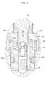
- Fig. 4 is a sectional view showing the detailed construction of the portion "A" of Fig. 3.
-
- Reference now should be made to the drawings. As shown in Fig. 3, inflow and outflow control solenoid valves according to the preferred embodiment of this invention are set in the
modulator block 30 of an EHB. In the present invention, the general shape of the modulator block and the inflow control solenoid valve remains the same as that described for the conventional embodiment of Fig. 2, but the construction of the outflow control solenoid valve is changed to accomplish the object of this invention. Those elements common to both the conventional embodiment and this invention will thus carry the same reference numerals. - The solenoid valve for brake systems of this invention is an NC-type solenoid valve, and used as the outflow control solenoid valve, which is set in the
modulator block 30 of an EHB to control the oil return line of the EHB. As shown in Fig. 3, two NC-type solenoid valves modulator block 30, respectively. Of the twovalves solenoid valve 10, which is set in the left-hand side of themodulator block 30, is an inflow control solenoid valve for controlling the oil supply line, which feeds pressurized oil from theaccumulator 7 of Fig. 1 to thewheel brake cylinder 8. The NC-type solenoid valve 40, which is set in the right-hand side of theblock 30, is an outflow control solenoid valve for controlling the oil return line, which returns oil from thebrake cylinder 8 to theoil tank 5. Since the outflowcontrol solenoid valve 40 is the valve of this invention, only the construction and operation of thevalve 40 will be described in the following description. - In the same manner as the inflow
control solenoid valve 10, the outflowcontrol solenoid valve 40 comprises ahollow valve housing 41, which is forcibly fitted in avalve seating hole 35 of themodulator block 30 as shown in Figs. 3 and 4. Thevalve 40 also has acylindrical armature 42, which is integrated with aplunger 42a axially and movably received in thebore 41c of thehollow valve housing 41. A hollowcylindrical sleeve 43 is connected at the lower end thereof to the upper end of thevalve housing 41, and axially and movably receives the body of thearmature 42 therein. Amagnetic valve core 44 is set in the upper end of thesleeve 43. Thecylindrical armature 42 has an outer diameter corresponding to the inner diameter of thesleeve 43, and so thearmature 42 axially moves along the internal surface of thesleeve 43 in opposite directions. Theplunger 42a of thearmature 42 is inserted into thebore 41c of thevalve housing 41, and opens or closes the oil passage of thevalve 40. - An
exciting coil 45 is provided outside thesleeve 43 andvalve core 44 for moving thearmature 42 inside thesleeve 43. Areturn spring 46 is positioned between thearmature 42 and thevalve core 44 inside thesleeve 43, and elastically supports thearmature 42 relative to thevalve core 44 such that it normally biases thearmature 42 in a direction toward thevalve housing 41 when theexciting coil 45 is turned off. - A
control ball 42b is set at the tapered lower end of theplunger 42a received in thebore 41c of thevalve housing 41, and opens or closes the oil passage of thevalve 40. A hollowcylindrical valve seat 47 is axially set in thebore 41c of thevalve housing 41. Thisvalve seat 47 has anorifice 47a at the center thereof, such that theorifice 47a is opened or closed by thecontrol ball 42b in accordance with an axial movement of theplunger 42a inside thebore 41c. That is, when theplunger 42a integrated with thearmature 42 is axially moved in thebore 41c, thecontrol ball 42b opens or closes theorifice 47a, thus opening and closing the oil passage of thesolenoid valve 40. - In the outflow
control solenoid valve 40 of this invention, anoil inlet passage 41a is formed at the middle portion of the sidewall of thevalve housing 41 as shown in Fig. 4. Aradial oil port 47b is formed in the sidewall of thevalve seat 47 to allow theoil inlet passage 41a to communicate with theorifice 47a of thevalve seat 47. That is, thevalve seat 47 has theradial oil port 47b on its sidewall, and so theoil inlet passage 41a of thevalve housing 41 communicates with theorifice 47a of thevalve seat 47 through theoil port 47b. The lower end of thebore 41c of thevalve housing 41 is closed by aplug 48, and so pressurized oil, introduced into thevalve seat 47 and the lower portion of thebore 41c through theoil inlet passage 41a, flows toward theplunger 42a through theorifice 47a. Anoil outlet passage 41 b is axially formed in the sidewall of thevalve housing 41. Pressurized oil, discharged upward from theorifice 47a, flows to a space defined under the bottom of thevalve housing 41 through theoil outlet passage 41 b. In such a case, theoil outlet passage 41b axially extends in the sidewall of thevalve housing 41 in parallel to thebore 41c, and communicates at its top end with thebore 41c at a position above thevalve seat 47. - Due to such a structure of the outflow
control solenoid valve 40, inlet oil, flowing from theoil inlet passage 41 a formed at the middle portion of the sidewall of thehousing 41, passes through theradial oil port 47b of thevalve seat 47 to be introduced into thevalve seat 47 and the lower portion ofbore 41c. The oil is, thereafter, discharged from thevalve seat 47 toward theplunger 42a through theorifice 47a, and flows downward through theoil outlet passage 41 b to reach the space defined under the bottom of thevalve housing 41. - The operational effect of the outflow control solenoid valve of this invention will be described herein below.
- When the
exciting coil 45 is turned off, theplunger 42a of thearmature 42 is biased downward by the restoring force of thereturn spring 46, thus being fully inserted into thebore 41c of thevalve housing 41. In such a case, thecontrol ball 42b of theplunger 42a closes theorifice 47a of thevalve seat 47. - When the
exciting coil 45 is turned on, theplunger 42a of thearmature 42 moves toward thevalve core 44 by the electromagnetic force generated between thearmature 42 and thevalve core 44. Thecontrol ball 42b of theplunger 42a moves from theorifice 47a, thus opening theorifice 47a and allowing pressurized oil to flow through theopen orifice 47a. - That is, oil flows into the
valve seat 47 and the lower portion of thebore 41c through theoil inlet passage 41a of thevalve housing 41 and theradial oil port 47b of thevalve seat 47. The oil is, thereafter, discharged upward from thevalve seat 47 and the lower portion of thebore 41 c toward theplunger 42a through theopen orifice 47a, and flows downward through theoil outlet passage 41b into the space defined under the bottom of thevalve housing 41. - In a detailed description, when the
orifice 47a of thevalve seat 47 is opened, oil introduced into thevalve seat 47 and the lower portion of thebore 41c through theoil inlet passage 41 a passes upward through theopen orifice 47a toward theplunger 42a, and flows downward through theoil outlet passage 41 b to reach the space under the bottom of thevalve housing 41. Therefore, the outflowcontrol solenoid valve 40 provides a "self-equilibrating effect" in the same manner as the inflowcontrol solenoid valve 10. Due to such a self-equilibrating effect, it is easy to control the operation of the outflowcontrol solenoid valve 40. That is, a large pressure difference is formed between the inlet and outlet of theorifice 47a at the initial stage of opening theorifice 47a, and so oil pressure inside theorifice 47a acts in an upward direction wherein theplunger 42a moves to open theorifice 47a, thus biasing theplunger 42a upward. After a predetermined lengthy period of time passes, theplunger 42a sufficiently opens theorifice 47a. The pressure difference between the inlet and outlet of theorifice 47a is thus reduced to a predetermined level. In such a case, the flow rate of oil through theorifice 47a is increased, but the oil pressure inside theorifice 47a is reduced. Theplunger 42a thus has a tendency to close theorifice 47a. The outflowcontrol solenoid valve 40 provides the "self-equilibrating effect", and it is easy to control the operation of the outflowcontrol solenoid valve 40. - As described above, the present invention provides a solenoid valve for brake systems. This solenoid valve is preferably used as an outflow control NC-type solenoid valve mounted on the oil return line of an EHB. In this valve, the oil passage structure is improved to have a self-equilibrating effect in the valve. That is, return oil is introduced into the valve housing of the solenoid valve through an oil inlet passage formed at the sidewall of the valve housing, and flows upward from the valve housing toward the plunger through an orifice, and flows downward through an oil outlet passage to reach a space defined under the bottom of the solenoid valve. This NC-type solenoid valve thus provides a self-equilibrating effect, even though it is used as an outflow control solenoid valve, and it is easily controlled during the operation of a brake system.
- Although a preferred embodiment of the present invention has been described for illustrative purposes, those skilled in the art will appreciate that various modifications, additions and substitutions are possible, without departing from the scope and spirit of the invention as disclosed in the accompanying claims.
Claims (1)
- A solenoid valve for brake systems, comprising:a hollow valve housing having an oil inlet passage on a sidewall thereof, with a bore axially defined in said valve housing;a plunger movably received in said bore of the valve housing so as to axially move in the bore in opposite directions by an electric force;a valve seat set in said bore of the valve housing, with an orifice axially formed in said valve seat such that the orifice is opened or closed by an end of said plunger in accordance with an axial movement of the plunger;a radial oil port formed on a sidewall of said valve seat so as to allow oil from the oil inlet passage of the valve housing to flow into the valve seat through the radial oil port, and flow from the valve seat toward the plunger through said orifice of the valve seat;a plug closing a lower end of the bore of said valve housing, thus allowing the oil to flow from the valve seat toward the plunger through the orifice; andan oil outlet passage axially formed in the sidewall of said valve housing in parallel to the bore such that the oil outlet passage communicates at a top end thereof with an outlet of said orifice, said oil outlet passage feeding the oil from the outlet of said orifice to an area under a bottom of said valve housing.
Applications Claiming Priority (2)
| Application Number | Priority Date | Filing Date | Title |
|---|---|---|---|
| KR1020010058532A KR20030025485A (en) | 2001-09-21 | 2001-09-21 | Solenoid valve for brake system |
| KR2001058532 | 2001-09-21 |
Publications (2)
| Publication Number | Publication Date |
|---|---|
| EP1295769A1 true EP1295769A1 (en) | 2003-03-26 |
| EP1295769B1 EP1295769B1 (en) | 2004-06-02 |
Family
ID=19714537
Family Applications (1)
| Application Number | Title | Priority Date | Filing Date |
|---|---|---|---|
| EP02007227A Expired - Lifetime EP1295769B1 (en) | 2001-09-21 | 2002-03-28 | Solenoid valve for brake systems |
Country Status (6)
| Country | Link |
|---|---|
| US (1) | US6588857B2 (en) |
| EP (1) | EP1295769B1 (en) |
| JP (1) | JP2003112619A (en) |
| KR (1) | KR20030025485A (en) |
| CN (1) | CN1248888C (en) |
| DE (1) | DE60200582T2 (en) |
Cited By (1)
| Publication number | Priority date | Publication date | Assignee | Title |
|---|---|---|---|---|
| FR2956465A1 (en) * | 2010-02-17 | 2011-08-19 | Bosch Gmbh Robert | ELECTROMAGNETIC VALVE HAVING A VALVE BODY IN SEVERAL PARTS |
Families Citing this family (14)
| Publication number | Priority date | Publication date | Assignee | Title |
|---|---|---|---|---|
| US20070140872A1 (en) * | 2005-12-16 | 2007-06-21 | Hutt Richard S | Compressor assembly for air conditioner system |
| KR100839715B1 (en) * | 2007-05-02 | 2008-06-19 | 현대모비스 주식회사 | Side flow path inlet type solenoid valve |
| KR20100003784A (en) * | 2008-07-02 | 2010-01-12 | 주식회사 만도 | Solenoid valve for brake system and manufacturing method thereof |
| KR101309512B1 (en) * | 2008-10-21 | 2013-09-24 | 주식회사 만도 | Solenoid valve for brake system |
| KR101024500B1 (en) * | 2009-02-17 | 2011-03-31 | 주식회사 만도 | Solenoid Valve for Electronic Control Brake System |
| JP5471734B2 (en) * | 2009-06-03 | 2014-04-16 | トヨタ自動車株式会社 | solenoid valve |
| KR101645730B1 (en) * | 2010-04-14 | 2016-08-04 | 현대모비스 주식회사 | Breaking pressure control valve |
| KR101294674B1 (en) | 2011-11-02 | 2013-08-09 | 주식회사 만도 | Solenoid valve for brake system |
| KR20140045676A (en) * | 2012-10-09 | 2014-04-17 | 주식회사 만도 | Solenoid valve for brake system |
| GB2529201A (en) * | 2014-08-13 | 2016-02-17 | Batmark Ltd | Device and method |
| DE102015122229A1 (en) * | 2015-12-18 | 2017-06-22 | Samson Ag | Valve |
| CN106369184A (en) * | 2016-10-10 | 2017-02-01 | 合肥协力液压科技有限公司 | Reversing solenoid valve |
| IT202000015367A1 (en) * | 2020-06-25 | 2021-12-25 | Raicam Driveline S R L | ANTI-LOCK BRAKING UNIT FOR A HYDRAULIC BRAKING SYSTEM, ESPECIALLY FOR BICYCLES |
| US12043228B2 (en) * | 2021-03-01 | 2024-07-23 | ZF Active Safety US Inc. | Apparatus and method for control of a hydraulic brake system |
Citations (2)
| Publication number | Priority date | Publication date | Assignee | Title |
|---|---|---|---|---|
| US5681098A (en) * | 1995-08-29 | 1997-10-28 | Kelsey Hayes | Anti-locking brake system with a switchable orifice control valve |
| DE19914516A1 (en) * | 1998-03-30 | 1999-10-07 | Kelsey Hayes Co | Procedure for controlling separating valve of car braking system |
Family Cites Families (11)
| Publication number | Priority date | Publication date | Assignee | Title |
|---|---|---|---|---|
| KR840000405A (en) * | 1982-06-22 | 1984-02-22 | 김선흥 | Braking Flow Control Device for Automobile Using Pascal's Principle |
| JP3294382B2 (en) * | 1992-10-30 | 2002-06-24 | 株式会社デンソー | Flow control valve |
| DE19531468B4 (en) * | 1995-08-26 | 2007-05-24 | Robert Bosch Gmbh | Hydraulic unit for a brake system with an anti-lock device |
| JPH1067310A (en) * | 1996-08-28 | 1998-03-10 | Aisin Seiki Co Ltd | Brake hydraulic modulator for vehicles |
| DE19700980A1 (en) * | 1997-01-14 | 1998-07-16 | Teves Gmbh Alfred | Solenoid valve |
| DE19710353A1 (en) * | 1997-03-13 | 1998-09-17 | Bosch Gmbh Robert | Solenoid valve with integrated check valve |
| JP3773146B2 (en) * | 1997-09-12 | 2006-05-10 | 日清紡績株式会社 | Hydraulic control valve device |
| US6231029B1 (en) * | 1998-11-13 | 2001-05-15 | Mando Machinery Corporation | Solenoid valve for anti-lock brake system |
| US6364430B1 (en) * | 1998-11-13 | 2002-04-02 | Mando Machinery Corporation | Solenoid valve for anti-lock brake system |
| US6276764B1 (en) * | 1998-11-17 | 2001-08-21 | Mando Machinery Corporation | Solenoid valve for anti-lock brake system |
| KR200267459Y1 (en) * | 1999-02-06 | 2002-03-09 | 밍 루 | Hydraulic brake device and normal close valve having bypass valve |
-
2001
- 2001-09-21 KR KR1020010058532A patent/KR20030025485A/en not_active Ceased
-
2002
- 2002-03-26 US US10/108,048 patent/US6588857B2/en not_active Expired - Lifetime
- 2002-03-27 JP JP2002087984A patent/JP2003112619A/en active Pending
- 2002-03-28 EP EP02007227A patent/EP1295769B1/en not_active Expired - Lifetime
- 2002-03-28 DE DE60200582T patent/DE60200582T2/en not_active Expired - Lifetime
- 2002-04-19 CN CNB021181144A patent/CN1248888C/en not_active Expired - Fee Related
Patent Citations (2)
| Publication number | Priority date | Publication date | Assignee | Title |
|---|---|---|---|---|
| US5681098A (en) * | 1995-08-29 | 1997-10-28 | Kelsey Hayes | Anti-locking brake system with a switchable orifice control valve |
| DE19914516A1 (en) * | 1998-03-30 | 1999-10-07 | Kelsey Hayes Co | Procedure for controlling separating valve of car braking system |
Cited By (1)
| Publication number | Priority date | Publication date | Assignee | Title |
|---|---|---|---|---|
| FR2956465A1 (en) * | 2010-02-17 | 2011-08-19 | Bosch Gmbh Robert | ELECTROMAGNETIC VALVE HAVING A VALVE BODY IN SEVERAL PARTS |
Also Published As
| Publication number | Publication date |
|---|---|
| EP1295769B1 (en) | 2004-06-02 |
| KR20030025485A (en) | 2003-03-29 |
| DE60200582D1 (en) | 2004-07-08 |
| CN1248888C (en) | 2006-04-05 |
| US20030057767A1 (en) | 2003-03-27 |
| JP2003112619A (en) | 2003-04-15 |
| DE60200582T2 (en) | 2005-06-16 |
| US6588857B2 (en) | 2003-07-08 |
| CN1410303A (en) | 2003-04-16 |
Similar Documents
| Publication | Publication Date | Title |
|---|---|---|
| US6588857B2 (en) | Solenoid valve for brake systems | |
| EP1979212B1 (en) | Vehicular brake system | |
| KR970001502B1 (en) | Brake system | |
| CN101580060B (en) | Solenoid valve with short axis | |
| JPS61263860A (en) | Hydraulic antiskid brake system for automobile | |
| US8281802B2 (en) | Valve for anti-lock brake system | |
| JP5381514B2 (en) | Brake hydraulic pressure control device | |
| US20120139331A1 (en) | Brake apparatus | |
| EP1439105B1 (en) | Brake traction control valve | |
| US6364431B1 (en) | Electromagnetic valve and hydraulic circuit | |
| JP4613907B2 (en) | solenoid valve | |
| KR100498693B1 (en) | Anti-lock Brake System Pump Housing | |
| KR101309512B1 (en) | Solenoid valve for brake system | |
| US6688706B2 (en) | Hydraulic pressure control apparatus for a brake system of a vehicle | |
| JPH1067310A (en) | Brake hydraulic modulator for vehicles | |
| US6086165A (en) | Solenoid controlled valve and antilock control apparatus using the same | |
| CN103978968A (en) | Actuator for controlling brake fluid pressure | |
| JP2519922Y2 (en) | Anti-skid brake device | |
| JP2005308156A (en) | Hydraulic valve | |
| KR102443205B1 (en) | Filter assembly for solenoid valve with check valve and solenoid valve including same | |
| KR100465809B1 (en) | 3-port solenoid valve for anti-lock brake apparatus | |
| KR20070096447A (en) | Solenoid Valve for Brake System | |
| JP2643313B2 (en) | Anti-skid device | |
| JP2000309263A (en) | Brake device with multiple actuation sources | |
| KR100550945B1 (en) | Pump Housing for ABS |
Legal Events
| Date | Code | Title | Description |
|---|---|---|---|
| PUAI | Public reference made under article 153(3) epc to a published international application that has entered the european phase |
Free format text: ORIGINAL CODE: 0009012 |
|
| 17P | Request for examination filed |
Effective date: 20020426 |
|
| AK | Designated contracting states |
Kind code of ref document: A1 Designated state(s): AT BE CH CY DE DK ES FI FR GB GR IE IT LI LU MC NL PT SE TR |
|
| AX | Request for extension of the european patent |
Extension state: AL LT LV MK RO SI |
|
| 17Q | First examination report despatched |
Effective date: 20030624 |
|
| GRAP | Despatch of communication of intention to grant a patent |
Free format text: ORIGINAL CODE: EPIDOSNIGR1 |
|
| AKX | Designation fees paid |
Designated state(s): DE GB |
|
| GRAS | Grant fee paid |
Free format text: ORIGINAL CODE: EPIDOSNIGR3 |
|
| GRAA | (expected) grant |
Free format text: ORIGINAL CODE: 0009210 |
|
| AK | Designated contracting states |
Kind code of ref document: B1 Designated state(s): DE GB |
|
| REG | Reference to a national code |
Ref country code: GB Ref legal event code: FG4D |
|
| REF | Corresponds to: |
Ref document number: 60200582 Country of ref document: DE Date of ref document: 20040708 Kind code of ref document: P |
|
| REG | Reference to a national code |
Ref country code: IE Ref legal event code: FG4D |
|
| PLBE | No opposition filed within time limit |
Free format text: ORIGINAL CODE: 0009261 |
|
| STAA | Information on the status of an ep patent application or granted ep patent |
Free format text: STATUS: NO OPPOSITION FILED WITHIN TIME LIMIT |
|
| 26N | No opposition filed |
Effective date: 20050303 |
|
| PGFP | Annual fee paid to national office [announced via postgrant information from national office to epo] |
Ref country code: GB Payment date: 20190107 Year of fee payment: 18 Ref country code: DE Payment date: 20181120 Year of fee payment: 18 |
|
| REG | Reference to a national code |
Ref country code: DE Ref legal event code: R119 Ref document number: 60200582 Country of ref document: DE |
|
| PG25 | Lapsed in a contracting state [announced via postgrant information from national office to epo] |
Ref country code: DE Free format text: LAPSE BECAUSE OF NON-PAYMENT OF DUE FEES Effective date: 20201001 |
|
| GBPC | Gb: european patent ceased through non-payment of renewal fee |
Effective date: 20200328 |
|
| PG25 | Lapsed in a contracting state [announced via postgrant information from national office to epo] |
Ref country code: GB Free format text: LAPSE BECAUSE OF NON-PAYMENT OF DUE FEES Effective date: 20200328 |