EP1295704A2 - Tire building drum - Google Patents
Tire building drum Download PDFInfo
- Publication number
- EP1295704A2 EP1295704A2 EP02256321A EP02256321A EP1295704A2 EP 1295704 A2 EP1295704 A2 EP 1295704A2 EP 02256321 A EP02256321 A EP 02256321A EP 02256321 A EP02256321 A EP 02256321A EP 1295704 A2 EP1295704 A2 EP 1295704A2
- Authority
- EP
- European Patent Office
- Prior art keywords
- segment
- expanding
- bead
- building drum
- bead lock
- Prior art date
- Legal status (The legal status is an assumption and is not a legal conclusion. Google has not performed a legal analysis and makes no representation as to the accuracy of the status listed.)
- Granted
Links
Images





Classifications
-
- B—PERFORMING OPERATIONS; TRANSPORTING
- B29—WORKING OF PLASTICS; WORKING OF SUBSTANCES IN A PLASTIC STATE IN GENERAL
- B29D—PRODUCING PARTICULAR ARTICLES FROM PLASTICS OR FROM SUBSTANCES IN A PLASTIC STATE
- B29D30/00—Producing pneumatic or solid tyres or parts thereof
- B29D30/06—Pneumatic tyres or parts thereof (e.g. produced by casting, moulding, compression moulding, injection moulding, centrifugal casting)
- B29D30/08—Building tyres
- B29D30/20—Building tyres by the flat-tyre method, i.e. building on cylindrical drums
- B29D30/24—Drums
- B29D30/244—Drums for manufacturing substantially cylindrical tyre components with cores or beads, e.g. carcasses
- B29D30/245—Drums for the single stage building process, i.e. the building-up of the cylindrical carcass and the toroidal expansion of it are realised on the same drum
-
- B—PERFORMING OPERATIONS; TRANSPORTING
- B29—WORKING OF PLASTICS; WORKING OF SUBSTANCES IN A PLASTIC STATE IN GENERAL
- B29D—PRODUCING PARTICULAR ARTICLES FROM PLASTICS OR FROM SUBSTANCES IN A PLASTIC STATE
- B29D30/00—Producing pneumatic or solid tyres or parts thereof
- B29D30/06—Pneumatic tyres or parts thereof (e.g. produced by casting, moulding, compression moulding, injection moulding, centrifugal casting)
- B29D30/08—Building tyres
- B29D30/20—Building tyres by the flat-tyre method, i.e. building on cylindrical drums
- B29D30/24—Drums
- B29D30/26—Accessories or details, e.g. membranes, transfer rings
- B29D2030/2635—Central bladder, e.g. elastic membrane, sleeve, envelope, diaphragm, which covers the central portion of the drum, e.g. covering the toroidally expandable rigid segments
-
- B—PERFORMING OPERATIONS; TRANSPORTING
- B29—WORKING OF PLASTICS; WORKING OF SUBSTANCES IN A PLASTIC STATE IN GENERAL
- B29D—PRODUCING PARTICULAR ARTICLES FROM PLASTICS OR FROM SUBSTANCES IN A PLASTIC STATE
- B29D30/00—Producing pneumatic or solid tyres or parts thereof
- B29D30/06—Pneumatic tyres or parts thereof (e.g. produced by casting, moulding, compression moulding, injection moulding, centrifugal casting)
- B29D30/08—Building tyres
- B29D30/20—Building tyres by the flat-tyre method, i.e. building on cylindrical drums
- B29D30/32—Fitting the bead-rings or bead-cores; Folding the textile layers around the rings or cores
- B29D2030/3221—Folding over means, e.g. bladders or rigid arms
- B29D2030/3264—Folding over means, e.g. bladders or rigid arms using radially expandable, contractible mechanical means, e.g. circumferentially spaced arms, spring rollers, cages
Definitions
- the present invention relates to a tire building drum for building a green tire from a green case or a carcass band composed of members including a carcass member of a tire.
- a cylindrical carcass band or green case is generally built on a first building drum, a cylindrical belt tread band is built on a second building drum by bonding a belt member with a tread rubber, and then the cylindrical carcass and the cylindrical belt tread band are respectively transferred onto a green tire building drum. Subsequently, while holding both bead cores of the carcass band or the green case in place, the main body of the carcass member extending between the bead cores is swelled radially outwards to contact a cylindrical inner side of the belt tread band placed outside thereof, so that the main body and the belt tread band are tightly attached to each other by pressure.
- a green tire building apparatus for use in such a process has a pair of bead lock sections for holding both bead cores, and a center bladder for sealing spaces defined between the bead lock sections, wherein the center bladder is entirely made of rubber.
- the main body of the carcass member can be toroidally swelled radially outwards by pressurizing the center bladder and thereby applying inner pressure to the space.
- the rubber bladder is assigned primarily with a sealing function, so that the main body of the carcass member itself is designed to support the inner pressure and determine the shape of the swelled main body of the carcass member. While this process is widely used due to its advantage in terms of cost, which results from use of the rubber bladder, there is a potential problem that the uniformity of the product tire tends to deteriorate if any portion with uneven strength is present in the main body of the carcass member such that the main body of the carcass member assumes uneven shape when it is swelled.
- the main body of the carcass member has a swelled shape that is as close to the shape of the product tire as possible, already at the green tire building stage so as to minimize deformation of the green tire during vulcanization.
- this is practically difficult to realize by the above-mentioned prior art process, since the swelled shape is uniquely determined by the strength distribution in the main body of the carcass member.
- JP-A-8-011239 proposes a method wherein the building drum has a center bladder embedded with cords, so as to determine the swelled shape of the main body of the carcass member by applying tension to the cords.
- An additional or alternative measure is proposed in EP-A-0661151 or U.S. Patent No.5,164,035, for example, wherein a building drum is provided, instead of, or in addition to the center bladder, with a plurality of rigid bodies in the form of metal segments abutting on each other in the circumferential direction and made radially expandable/contractible so as to determine the swelled shape of the carcass member when expanded..
- the present invention has been achieved taking these problems into consideration and it is an object of the present invention to provide a green tire building drum including a plurality of expansible/contractible rigid segments and being capable of continuously building tires in various dimension with a desired sequence.
- a tire building drum including a hollow main shaft, a pair of bead lock sections arranged concentric with the main shaft and respectively holding a bead core of a tire, and a radially expansible/contractible carcass-supporting body defining a inner shape of a carcass member extending between the bead cores, the tire building drum comprising a pair of core bodies concentric with the main shaft, the pair of core bodies constituting the carcass-supporting body and comprising a plurality of expansible/contractible rigid segments circumferentially abutting on and engaging with each other, a pair of sliders on which the core body and the bead lock section are mounted on a single side in the axial direction, the sliders being movable toward and away from each other in the axial direction, slider-moving means for moving these sliders to any required radial position, and segment-expanding/contracting means for expanding/contracting the segments of each core body to any required radial position.
- the tire carcass-supporting body is composed of the core bodies arranged on the both sides of the main shaft, and there are provided the pair of sliders which is equipped with these core bodies and the bead lock sections and move toward or away from each other in the axial direction, and the slider-moving means for moving these sliders to and stopping at any required radial position. Therefore, a green tire having any bead core distance and belt members of any width can be built without replacing any part including a segment.
- each of the core bodies on the both sides is composed of the plurality of expansible/contractible segments circumferentially abutting on and engaged with each other, and there are provided on the both sides the segment-expanding/contracting means for radially expanding the segments to and stopped at any diameter. Therefore, a green tire having belt members of any inner diameter can be built without replacing any part including a segment.
- the carcass-supporting body is composed of the plurality of rigid segments, and these segments are engaged with and abutted on each other at any diameter. Therefore, when the main body of the carcass member is radIally expanded, a supporting face which uniformly supports the main body over the whole surface in width and circumferential directions and has high rigidity can be formed to realize a swelled shape of the carcass member highly accurately. Thus, a tire having satisfactory uniformity can be build.
- the radially expanded main body of the carcass member is supported by a face having high rigidity, so that the belt members and the tread rubber can be directly and accurately bonded on the circumference of the main body.
- a belt tread band is built on another drum and then transferred to be joined with the carcass member.
- the method using the tire building drum according to the present invention eliminates fluctuation in accuracy of the position during the transfer, and thus contributes to improve the uniformity.
- the slider-moving means comprises a screw shaft provided in the hollow main shaft, and the screw shaft comprises a slider-driving connector joined to an output shaft of a servo motor, and a pair of thread sections screwed into the sliders and having mutually opposite leads.
- the pair of sliders being movable toward and away from each other are driven by screwing into the pair to the thread sections provided in a screw shaft and having mutually opposite leads, so that the sliders can be moved axially symmetric to each other in any situation. Therefore, regardless of dimension of a tire to be built, the center point of the sliders never shifts during both the expansion and the contraction of the drum, and thus the tire can be built highly accurately.
- the screw shaft is provided with the slider-driving connector driven by the servo motor, so that a dimensional change of the drum can be instantly conducted by setting preset values for each dimension which correspond to the stopping positions of the sliders and determine positions of a controller of the building apparatus to stop the servo motor, and selecting the preset value according to the dimension of a tire to be built. Therefore, tires in various dimensions can be continuously built with satisfactory productivity.
- the drum can be compactly configured.
- the segment-expanding/contracting means comprises segment-expanding/contracting link sections joined to the segments, a segment-driving connector joined to a driving arm axially reciprocated by a servo motor, an axially movable segment-binding section for coupling the segment-expanding/contracting link sections to the segment-driving connector, and a break for breaking the segment-binding section.
- the pair of segment-expanding/contracting means are provided with the segment-expanding/contracting link sections joined to the segment, and the axially movable segment-binding section for coupling the segment-expanding/contracting link sections, so that the segments can be uniformly expanded or contracted over the whole circumference by moving the segment-expanding/contracting link sections in the axial direction. Therefore, the segments can be uniformly arranged on the circumference of a tire having any belt member-bonding diameter, so that a tire having good uniformity can be built.
- the segment-expanding/contracting means is provided with the segment-driving connector joined to a driving arm axially reciprocated by a servo motor, so that a dimensional change of the drum can be instantly conducted by setting preset values for each dimension which correspond to the stopping positions of expanding/contracting the segments and determine positions of a controller of the building apparatus to stop the servo motor, and selecting the preset value according to the dimension of a tire to be built. Therefore, tires in various dimensions can be continuously built.
- the segment-expanding/contracting means of the tire building drum is provided with a break for breaking the segment-binding section, so that accuracy in the stopping position can be improved.
- a centripetal force radially contracting the segments acts when a tension is applied to the belt members and the belt members are bonded on the outer periphery of the carcass member, a movement of the segment in the contracting direction accompanying to this can be prevented.
- a center bladder is arranged on the outer circumference of the segments, a contractive force of the center bladder composed of a elastically deformable body similarly acts, so that the movement of the segment in the contracting direction can be also prevented in this case.
- the bead lock sections each comprises a plurality of bead lock segments circumferentially abutting on each other and being radially expansible or contractible while maintaining their circular spatial relations, bead lock expanding/contracting link sections joined to the bead lock segments, axially movable bead lock binding sections joined to these link sections, and a bead lock cylinder for moving the bead lock binding sections.
- the bead lock segments can be expanded or contracted by moving the bead lock binding section in the axial direction, the bead cores can be uniformly held over the whole circumference. Further, since the bead lock segments are driven by the mounted bead lock cylinder, the building drum can be compactly configured.
- the tire building drum further comprises a center bladder comprising an elastically deformable body for sealing spaces between the sliders including the core body, the bladder having both axial ends mounted to the sliders.
- a center bladder comprising an elastically deformable body for sealing spaces between the sliders including the core body, the bladder having both axial ends mounted to the sliders.
- the tensioned center bladder smoothly fill the spaces between the segments on the outer periphery face of the segments formed by linking all the segments during the expansion of the segments. Therefore, the main body of the carcass member is more uniformly supported and a bonding face can be more uniformly configured when the main body is radially expanded and the belt members are bonded thereon.
- the carcass member is turned up about the bead cores to form a green case and, thereafter, the green case is transferred onto another drum, it is necessary to release the held bead cores once and then hold the bead cores again.
- a deformation occurs due to a remaining stress around the bead core accompanying to turning up. As a result, it is difficult to hold the bead core again while precisely maintaining the original state.
- the tire building drum further comprises turn-up mechanisms for turning side portions of the carcass member up about the respective bead cores, the turn-up mechanisms being mounted on each of the sliders.
- a so-called "carcass band” which is a carcass member prior to turn up about the bead core can be transferred onto the green tire building drum and subsequently be turn up on the drum.
- a green tire is built by continuously joining the belt members and the tread rubber while locking the bead core, so that the bead core is not held again until the green tire building is completed.
- a tire having a high degree of accuracy can be built.
- the turn-up mechanisms each comprises a plurality of turn-up rollers circumferentially abutting on each other and being radially expansible or contractible while maintaining their circular spatial relations, an external roller-driving contact section that can be reciprocated by contacting an axially reciprocating external driving arm, and rigid turn-up fingers, the fingers each having one end connected to the turn-up roller and the other end pivotly connected to the external roller-driving contact section.
- the turn-up mechanisms are provided with the plurality of the turn-up rollers circumferentially abutting on each other and turning the up carcass member by moving the outside of the carcass member from the vicinity of the bead core to the edge of the carcass member, the rigid turn-up fingers each supporting the rollers, and the external roller-driving contact section pivotly connecting these turn-up fingers in a swingable manner to bind them. Therefore, as compared with a method in which the turning up is conducted by means of the turn-up bladder composed of an elastically deformable body, since the carcass member is turned up by moving the external roller-driving contact section toward the center of the axial, the turning up can be uniformly performed in the circumferential direction. Thus, a tire having satisfactory uniformity can be built.
- FIG. 1 is a sectional view of a tire building drum 1 according to an embodiment of the present invention.
- the tire building drum 1 has a hollow main shaft 10, bead lock sections 20 arranged concentric with the main shaft 10 on the left and right sides and respectively holding a bead core of a tire, a pair of core bodies 30 on the left and right sides composed of a plurality of rigid segments 31 radially expanding/contracting with the main shaft 10 as center, and sliders 40 having the bead lock sections 20 and the core bodies 30 of the same side and moving toward and away from each other in the axial direction.
- the tire building drum 1 further include a screw shaft 50 provided in the hollow section of the main shaft 10 and constituting a slider-moving means for moving the sliders 40, a pair of segment-expanding/contracting means for expanding/contracting the segments 31 arranged on the left side or the right side corresponding to the respective core bodies 30, and a pair of turn-up mechanism on the left and right sides for turning side portions of the carcass member up about the respective bead cores.
- a screw shaft 50 provided in the hollow section of the main shaft 10 and constituting a slider-moving means for moving the sliders 40, a pair of segment-expanding/contracting means for expanding/contracting the segments 31 arranged on the left side or the right side corresponding to the respective core bodies 30, and a pair of turn-up mechanism on the left and right sides for turning side portions of the carcass member up about the respective bead cores.
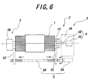
- the tire building apparatus 2 has a building apparatus main body 3A fastened to one end of the main shaft 10 of the tire building drum 1 and driving the main shaft 10, and a supporting section 3B for supporting the other end of the main shaft 10 opposed to the main body 3A to form a dual supporting in cooperation with the main body 3A.
- the building apparatus 2 also has a slider-driving section 4 composed of an external shaft 4B connected to the screw shaft 50 of the building drum 1 and a servo motor 4A for rotating the screw shaft 50 via the external shaft 4B, and a reciprocally driving section 5 composed of a servo motor 5A for a reciprocating drive, left and right threads 5B driven by the servo motor 5A, and a pair of driving arms 5C screwed on the threads 5B and respectively moving to the left or the right in the same distance.
- the reciprocally driving section 5 can be engaged with segment-expanding/contracting means 60 to drive them, or can be abut against a turn-up mechanisms 70 to actuate them.
- the screw shaft 50 for moving the sliders 40 has a pair of thread sections 51 on the left and right sides with mutually opposite leads, and a slider-driving connector 52 joining the screw shaft 50 to the external shaft 4B driven by the servo motor 4A for rotation.
- Each of the sliders 40 is composed of a thread block 41 screwed on the thread section 51 located on the same side as the slider 40, a slider guide section 42 fixed on the thread block 41, guided by the main shaft 11 and sliding on the main shaft 11 in the axial direction, and a bead lock section-supporting section 43 fixedly mounted on the slider guide section 42 and extending radially outside of the slider guide section 42.
- the thread blocks 41 each screwed on the thread section 51 is mutually oppositely moved in the axial direction and in the same distance by externally rotating the screw shaft 50 via the slider-driving connector 52, so that each of the sliders 40 can be entirely moved toward and away from each other.
- both of the sliders 40 are mutually oppositely moved in the axis direction and exactly in the same distances by the rotation of the screw shaft 50. Therefore, when the main body of the carcass member is swelled while maintaining a cord path length extending between the bead cores, pushing the bead lock section 20 and the core body 30 toward the center, which is so-called width-approaching, in sync with the radial expansion of the segments 31 can be conducted at a high degree of accuracy. Moreover, since the slider 40 is driven by the external servo motor 4A via the screw shaft 50, the slider can stop at any axial position. Therefore, tires being different in length of the carcass cord between the bead cores, or tires being different in the width of the belt members can be continuously built without replacing the parts of the drum.
- a center bladder 45 for sealing spaces separated by the slider 40 is provided between the left and right sliders. Both side ends of the center bladder 45 are circularly attached to axially central side ends of the bead lock section-supporting sections 43 of the sliders 40.
- the center bladder 45 fills spaces between the segments 31 on the outer periphery face of the segments 31 during the segment 31 being radially expanded in a state where tension is applied to the center bladder 45. Therefore, the main body of the carcass member is more uniformly supported and a bonding face can be more uniformly configured when the belt members are bonded on the center bladder 45, which may contribute to improve the uniformity.
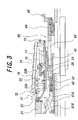
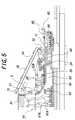
- FIGS. 2 to 5 are partially sectional fragmentary detail views each showing details of the slider 40, the segment-expanding/contracting mechanism 60, the bead lock section 20, and the turn-up mechanism 70 at different states of the tire building drum. With reference to these figures, each section is described below in detail. While FIG. 2 shows a state where the slider 40 lies axially outside, FIGS. 3 to 5 show states where the slider 40 has moved to the axially central side.
- Each segment-expanding/contracting means 60 for expanding/contracting segments 31 has segment-expanding/contracting link sections 61 which are joined to the segments 31, is circularly arranged and expands or contracts the segments 31, a segment-binding section 62 which binds the segment-expanding/contracting link sections 61 and axially slides on the slider guide section 42, a break 64 connected to the segment-binding section 62 via a connecting rod 63, and a segment driving connector 65 which is attached to the break 64 and is capable of engaging with the above-mentioned driving arm 5C.
- Each segment-expanding/contracting link section 61 is provided with a pair of parallel links 61A which are pivotly connected to pins attached the segment-binding sections 62 and pins connected to the segments 31 at both ends to swing in parallel with each other, as well as each has a swing link 61B which is pivotly connected a pin attached to one of the parallel links 61A and a pin fixedly provided on the slider guide section 62 at both ends.
- the break 64 When the break 64 is released and the driving arm 5C of the tire building apparatus 2 is engaged with the segment driving connector 65 to move the driving arm 5C in the axially center direction in the state as shown in FIG. 3, the break 64, the connection rod 63 and the segment-binding section 62 integratedly move in the axially inward direction to be the state as shown in FIG. 4.
- the segment-binding sections 62 are moved in the axially center direction by a distance larger than that of the slider guide section 42 of the slider 40 which is also moved in the axially center direction.
- the swing pin 61B pivotly connected to the to the slider guide section 42 and the pair of parallel pins 61A are cooperatively moved so that the segments 31 can be radially expanded while maintaining their positions.
- break 64 constituting the segment-expanding/contraction means 60 act to keep the radial positions of the segments 31 against contractive force of the center bladder 45 and force which radially contracts the segments when a tension is applied to the outer periphery of the center bladder 45 to bond the belt members.
- the break 64 has a cylinder 64A for including air, a taper piston having a corn-like taper section and reciprocating in the cylinder 64A, pressure springs 64B mounted in an air chamber located in the axially center direction from the taper piston 64C, and a taper ring 64D of which the outer surface is engaged with the corn-like taper section of the taper piston 64C and a break metal to be slid on the main shaft 10 is fixedly attached on the inner surface.
- the taper piston 64C By means of pressurization of the air chamber in the axially center side from the taper piston 64C, and by virtue of function of the pressure springs, the taper piston 64C is moved in the axially outward direction, and, therefore, the taper ring 64D is clamped via the taper surface to break against the radial contraction of the segments 31. On the contrary, by pressuring the air chamber in the axially outward side, the taper ring 64D is released from clamping to enable the segments 31 to be radially expanded or contracted.
- the bead lock section 20 has a bead lock segments 21 circumferentially abutting on each other and being radially expansible or contractible, bead lock expanding/contracting link sections 22 joined to the bead lock segments 21, axially movable bead lock binding sections 25 joined to these link sections 22, and a bead lock cylinder 24 which moves the bead lock binding sections 25 and is fixedly connected to the bead lock section-supporting section 43.
- the bead lock expanding/contracting link section 22 is provided with a pair of parallel links 22A of which both ends are pivotly connected to the bead lock segment 21 and the bead lock binding section 25, respectively, and a swing link 22B of which both ends are pivotly connected to bead lock segment 21 and the bead lock cylinder 24.
- each of the bead lock sections 21 can be axially expanded by the action of the parallel links 22A and the swing link 22B while maintaining their positions, as shown in FIG. 3. Contrary, when the inside of the bead lock cylinder 24 is depressurized to move the bead lock binding section 25 toward the axially outer direction, each of the bead lock sections 21 can be axially contracted via the bead lock expanding/contracting link section 22.
- Each of the turn-up mechanisms 70 has a base section 71 fixedly connected to the bead lock section-supporting section 43 of the slider 40, a plurality of turn-up roller 72 circumferentially abutting on each other and being radially expansible or contractible, an external roller-driving contact section swung on the base section 71 to reciprocate by contacting an axially reciprocating external driving arm 5C, turn-up fingers 74 having one end connected to the turn-up roller 72 and the other end pivotly connected to the external roller driving contact section 73, a return spring 75 of which both ends are engaged with the base section and the external roller driving contact section 73, and a plurality of rubber bands 76 fixedly provided on the outer circumference of the turn-up fingers 74.
- a turn-up section X of a carcass band composed of the side part of the carcass member and an optional side wall rubber is provided on a outer circumference formed by the circularly arranged turn-up fingers 74.
- the turn-up section X is turned up by radially expanding the turn-up fingers 74 and the expanding/contracting roller 72 connected to the fingers 74. That is, when the arm 5C is contacted the external roller driving contact section 73 to move it in the axially center direction, the external roller driving contact section 73 is moved along the base section 71 in the axially center direction and the turn-up fingers 74 pivotly connected to the external roller driving contact section 73 and the turn-up roller 72 are also moved in the axially center direction, as shown in FIG. 5.
- the turn-up roller 72 is restricted its movement in the axially center direction by the center bladder 45 which holds the turn-up section X and is radially expanded, the turn-up fingers 74 and the expanding/contracting roller 72 are radially expanded with the point pivotly connecting them to the external roller driving contact section 73 as the center, thereby turning up the turn-up section X.
- the external roller driving contact section 73 is moved in the axially outside direction by the action of the return spring 75, as well as the turn-up fingers 74 are radially contracted by the action of the rubber bands 76.
- a carcass band CB built on another drum and including carcass members C and bead cores B is transferred on the outer circumference of the tire building drum 1 in the state where the segments 31, the bead lock segments 21 and the turn-up fingers 74 of the tire building drum 1 are radially contracted, as shown in FIG. 8.
- the distance between the bead lock segments 21 of the bead lock section 20 is set according to the distance between both bead cores B of the carcass band CB.
- the bead lock segments 21 are radially expanded to hold the bead cores B.
- the segments 31 and the center bladder 45 are radially expanded while the axial distance between the bead lock sections 20 being narrowed.
- the inner pressure is delicately adjusted according to the diameter of the center bladder.
- the segment 31 and the center bladder 45 are radially expanded to a given maximum diameter according to the size of the tire.
- the turn-up section X is turned up by radially expanding the turn-up fingers 74 with moving it in the axially center direction.
- Belt members and a tread rubber are bonded on the outer circumference of the expanded carcass members.
- Plural rows of sidewall rubber having a ribbon-like shape are wrapped around the side part of the tire to from a side wall having a given sectional shape.
- a stitching operation is performed on it and the green tire is completed. Thereafter, the turn-up finger 74, the center bladder 45, the segment 31 and the bead lock segment are radially contracted to remove the green tire.
- a carcass supporting bodies is composed of a pair of core bodies arranged on the left and right sides of a main shaft, and there are provided sliders which is equipped with these core bodies and the bead lock sections and move toward and away from each other in the axial direction, and the slider-moving means for moving these sliders to and stopping at any required radial position, a green tire having any bead core distance and belt members of any width can be produced without replacing any part including the segments but only with changing settings of positions of the sliders to be stopped according to the dimension of the tire to be built.
- each of the core bodies on the both sides is composed of the plurality of expansible/contractible segments circumferentially abutting on and engaged with each other, and there are provided on the both sides the segment-expanding/contracting means for radially expanding the segments to and stopped at any diameter. Therefore, a green tire having belt members of any inner diameter can be built without replacing any part including a segment but only with changing a setting of a position of the segment expanding/contracting means to be stopped according to the dimension of the tire to be built.
Landscapes
- Engineering & Computer Science (AREA)
- Manufacturing & Machinery (AREA)
- Mechanical Engineering (AREA)
- Tyre Moulding (AREA)
Abstract
Description
Claims (7)
- A tire building drum (1) including a hollow main shaft (10), a pair of bead lock sections (20) arranged concentric with the main shaft and respectively holding a bead core of a tire, and a radially expansible/contractible carcass-supporting body (30,31) defining an inner shape of a carcass member extending between the bead cores, characterized by:a pair of core bodies (30) concentric with the main shaft (10), said pair of core bodies constituting the carcass-supporting body and comprising a plurality of expansible/contractible rigid segments (31) circumferentially abutting on and engaging with each other;a pair of sliders (40) on which the core body (30) and the bead lock section (20) are mounted on a single side in the axial direction, said sliders being movable toward and away from each other in the axial direction;slider-moving means (50,51,52) for moving said sliders (40) to any required radial position; andsegment-expanding/contracting means (60) for expanding/contracting the segments (31) of each core body (30) to any required radial position.
- A tire building drum as claimed in claim 1, characterized in that said slider-moving means comprises a screw shaft (50) provided in the hollow main shaft (10), said screw shaft comprising a slider-driving connector (52) joined to an output shaft of a servo motor, and a pair of thread sections (51) screwed into the sliders (40) and having mutually opposite leads.
- A tire building drum as claimed in claim 1 or 2, characterized in that said segment-expanding/contracting means (60) comprises segment-expanding/contracting link sections (61) joined to the segments (31), a segment-driving connector (65) joined to a driving arm (5C) axially reciprocated by a servo motor, an axially movable segment-binding section (62) for coupling the segment-expanding/contracting link sections (61) to the segment-driving connector (65), and a break (64) for breaking the segment-binding section (62).
- A tire building drum as claimed in any of claims 1 to 3, characterized in that said bead lock sections (20) each comprises a plurality of bead lock segments (21) circumferentially abutting on each other and being radially expansible or contractible while maintaining their circular spatial relations, bead lock expanding/contracting link sections (22) joined to the bead lock segments (21), axially movable bead lock binding sections (25) joined to said link sections (22), and a bead lock cylinder (24) for moving the bead lock binding sections (25).
- A tire building drum as claimed in any of claims 1 to 4, characterized by further comprising a center bladder (45) comprising an elastically deformable body for sealing spaces between the sliders (40) including the core body (30), said bladder having both axial ends mounted to the sliders.
- A tire building drum as claimed in any of claims 1 to 5, characterized by further comprising turn-up mechanisms (70) for turning side portions of the carcass member up about the respective bead cores (30), said turn-up mechanisms being mounted on each of the sliders (40).
- A tire building drum as claimed in claim 6, characterized in that said turn-up mechanisms (70) each comprises a plurality of turn-up rollers (72) circumferentially abutting on each other and being radially expansible or contractible while maintaining their circular spatial relations, an external roller-driving contact section (73) that can be reciprocated by contacting an axially reciprocating external driving arm (5C), and rigid turn-up fingers (74), said fingers each having one end connected to the turn-up roller (72) and the other end pivotly connected to the external roller-driving contact section (73).
Applications Claiming Priority (2)
| Application Number | Priority Date | Filing Date | Title |
|---|---|---|---|
| JP2001275866 | 2001-09-12 | ||
| JP2001275866A JP4651885B2 (en) | 2001-09-12 | 2001-09-12 | Tire molding drum |
Publications (3)
| Publication Number | Publication Date |
|---|---|
| EP1295704A2 true EP1295704A2 (en) | 2003-03-26 |
| EP1295704A3 EP1295704A3 (en) | 2004-08-11 |
| EP1295704B1 EP1295704B1 (en) | 2006-07-19 |
Family
ID=19100655
Family Applications (1)
| Application Number | Title | Priority Date | Filing Date |
|---|---|---|---|
| EP02256321A Expired - Lifetime EP1295704B1 (en) | 2001-09-12 | 2002-09-12 | Tire building drum |
Country Status (5)
| Country | Link |
|---|---|
| US (1) | US6880603B2 (en) |
| EP (1) | EP1295704B1 (en) |
| JP (1) | JP4651885B2 (en) |
| DE (1) | DE60213175T2 (en) |
| ES (1) | ES2267947T3 (en) |
Cited By (8)
| Publication number | Priority date | Publication date | Assignee | Title |
|---|---|---|---|---|
| WO2004048074A1 (en) | 2002-11-25 | 2004-06-10 | Bridgestone Corporation | Tire manufacturing method |
| WO2005097478A1 (en) * | 2004-04-05 | 2005-10-20 | Continental Aktiengesellschaft | Method for producing a pneumatic tire |
| EP1547757A4 (en) * | 2002-08-05 | 2006-04-19 | Bridgestone Corp | Tire molding drum and tire molding method |
| EP1674249A1 (en) * | 2004-12-23 | 2006-06-28 | The Goodyear Tire & Rubber Company | A method of making a tire using a high crown single stage tire building drum |
| EP1674248A1 (en) * | 2004-12-23 | 2006-06-28 | The Goodyear Tire & Rubber Company | High crown single stage tire building drum |
| WO2007110039A1 (en) * | 2006-03-14 | 2007-10-04 | Harburg-Freudenberger | Tyre building drum |
| EP2402149A1 (en) * | 2004-12-15 | 2012-01-04 | Vmi Epe Holland B.V. | Machines and methods for manufacturing of a component of a car tyre |
| WO2021058224A1 (en) * | 2019-09-25 | 2021-04-01 | Herbert Maschinen- und Anlagenbau GmbH & Co. KG | Drum and method for producing vehicle tyres |
Families Citing this family (32)
| Publication number | Priority date | Publication date | Assignee | Title |
|---|---|---|---|---|
| NL1026334C2 (en) * | 2004-06-04 | 2005-12-06 | Vmi Epe Holland | Tire drum assembly with storage mechanism for building an unvulcanized tire. |
| JP4402534B2 (en) | 2004-07-21 | 2010-01-20 | 株式会社ブリヂストン | Tire molding apparatus and method of using the same |
| JP4962833B2 (en) * | 2005-11-30 | 2012-06-27 | 横浜ゴム株式会社 | Molding drum |
| JP5164249B2 (en) * | 2007-05-29 | 2013-03-21 | 株式会社ブリヂストン | Tire molding method and tire molding apparatus |
| US20090133842A1 (en) * | 2007-11-26 | 2009-05-28 | Vmi Holland B.V.. | Tyre building drum for building an unvulcanised tyre |
| US8770251B2 (en) * | 2008-05-22 | 2014-07-08 | Vmi Holland B.V. | Tyre building drum for building an unvulcanised tyre |
| KR100965999B1 (en) | 2008-06-25 | 2010-06-24 | 금호타이어 주식회사 | Green Tire Manufacturing Equipment |
| JP5358272B2 (en) * | 2009-04-30 | 2013-12-04 | 株式会社ブリヂストン | Unvulcanized tire manufacturing apparatus and unvulcanized tire manufacturing method |
| ITMI20110721A1 (en) * | 2011-04-29 | 2012-10-30 | Pirelli | PROCESS AND EQUIPMENT FOR PACKING TIRES FOR VEHICLE WHEELS |
| DE102011050458A1 (en) * | 2011-05-18 | 2012-11-22 | Continental Reifen Deutschland Gmbh | Method for producing a vehicle tire |
| US9193122B2 (en) | 2011-09-26 | 2015-11-24 | The Goodyear Tire & Rubber Company | Solid deck bead lock drum |
| NL2007485C2 (en) * | 2011-09-27 | 2013-03-28 | Vmi Holland Bv | COMPOSITION AND METHOD FOR MANUFACTURING A GREEN TIRE AND / OR AIR SPRING |
| US10259181B2 (en) * | 2012-08-15 | 2019-04-16 | The Goodyear Tire & Rubber Company | Sleeveless tire building drum |
| JP6033334B2 (en) | 2013-01-17 | 2016-11-30 | 不二精工株式会社 | Bead forming apparatus and forming method |
| JP6212315B2 (en) * | 2013-07-23 | 2017-10-11 | 株式会社ブリヂストン | Carcass band folding device |
| US9283723B2 (en) | 2014-04-28 | 2016-03-15 | The Goodyear Tire & Rubber Company | Release mechanism for a tire building drum |
| JP6331764B2 (en) * | 2014-06-26 | 2018-05-30 | 横浜ゴム株式会社 | Pneumatic tire manufacturing method and forming drum |
| FR3031695B1 (en) * | 2015-01-16 | 2017-02-24 | Michelin & Cie | DRUM MAKING A PNEUMATIC BRAKE |
| NL2015246B1 (en) | 2015-07-30 | 2017-02-20 | Vmi Holland Bv | Tire building drum and a method for shaping tire components on said tire building drum. |
| KR101781797B1 (en) * | 2015-11-09 | 2017-10-23 | 한국타이어 주식회사 | Driving transmission device of greentire building drum |
| JP6233453B1 (en) * | 2016-06-06 | 2017-11-22 | 横浜ゴム株式会社 | Method and apparatus for attaching sound absorbing material to inner surface of tire |
| US10611112B2 (en) | 2016-07-22 | 2020-04-07 | The Goodyear Tire & Rubber Company | Center mechanism for tire building drum |
| US10245796B2 (en) | 2016-07-25 | 2019-04-02 | The Goodyear Tire & Rubber Company | Center deck assembly for tire building drum |
| NL2018011B1 (en) | 2016-12-16 | 2018-06-26 | Vmi Holland Bv | Drum half, tire building machine and method for operating said tire building machine |
| CN109175139B (en) * | 2018-09-04 | 2023-12-22 | 广东金亨制罐有限公司 | Intelligent vertical multi-station expansion tank forming machine |
| WO2020160012A1 (en) * | 2019-01-28 | 2020-08-06 | Davian Enterprises, LLC | Expandable belt and tread drum with reverse offset fingers |
| CN110202809B (en) * | 2019-07-01 | 2024-08-20 | 萨驰智能装备股份有限公司 | Tire building drum |
| FR3099407B1 (en) * | 2019-08-01 | 2021-07-02 | Michelin & Cie | EXPANDABLE DRUM FOR CONFORMING PNEUMATIC BANDAGES INCLUDING A PARALLELOGRAM EXTENSION DEVICE FOR HOLDING THE ROD |
| WO2021208988A1 (en) * | 2020-04-15 | 2021-10-21 | 桂林橡胶设计院有限公司 | Retraction and extension system, attachment drum, and processing method for tire bead attachment and molding |
| CN111391380B (en) * | 2020-04-15 | 2025-11-25 | 桂林橡胶设计院有限公司 | A mechanism for shrinking and stretching a fitted drum and a method for bonding triangular adhesive. |
| CN114683601B (en) * | 2020-12-31 | 2025-06-24 | 软控股份有限公司 | Tire production method and device |
| CN114683599B (en) * | 2020-12-31 | 2025-07-04 | 软控股份有限公司 | Method and device for adjusting specifications of forming drum |
Family Cites Families (12)
| Publication number | Priority date | Publication date | Assignee | Title |
|---|---|---|---|---|
| FR2093180A5 (en) | 1970-06-04 | 1972-01-28 | Gazuit Georges | Radial tyre forming drum |
| US3867231A (en) * | 1972-06-28 | 1975-02-18 | Goodyear Tire & Rubber | Tire building machine |
| US4007081A (en) | 1974-11-11 | 1977-02-08 | National-Standard Company | Tire building apparatus |
| US4010058A (en) * | 1975-05-16 | 1977-03-01 | The Goodyear Tire & Rubber Company | Tire building drum |
| FR2314821A1 (en) * | 1975-06-20 | 1977-01-14 | Zelant Gazuit | RADIAL CASING TIRE MAKING DRUM |
| JP3080966B2 (en) | 1990-05-02 | 2000-08-28 | 株式会社ブリヂストン | Tire building equipment |
| IT1261152B (en) | 1993-12-30 | 1996-05-09 | Bridgestone Firestone Tech | FORMING DRUM WITH METALLIC FORMING MODULE |
| JP3390532B2 (en) | 1994-06-30 | 2003-03-24 | 不二精工株式会社 | Bladder in radial tire molding equipment |
| JP4124829B2 (en) * | 1997-05-23 | 2008-07-23 | ブイエムアイ エペ ホランド ベスローテン フェンノートシャップ | Tire forming drum with folding device |
| EP1200247B1 (en) | 1999-07-30 | 2003-10-01 | PIRELLI PNEUMATICI Società per Azioni | Tyre assembling apparatus |
| US7152649B2 (en) | 1999-07-30 | 2006-12-26 | Pirelli Pneumatici S.P.A. | Tire-assembling apparatus |
| JP2001293793A (en) * | 2000-04-14 | 2001-10-23 | Bridgestone Corp | Tire building drum |
-
2001
- 2001-09-12 JP JP2001275866A patent/JP4651885B2/en not_active Expired - Fee Related
-
2002
- 2002-09-03 US US10/232,616 patent/US6880603B2/en not_active Expired - Lifetime
- 2002-09-12 EP EP02256321A patent/EP1295704B1/en not_active Expired - Lifetime
- 2002-09-12 DE DE60213175T patent/DE60213175T2/en not_active Expired - Lifetime
- 2002-09-12 ES ES02256321T patent/ES2267947T3/en not_active Expired - Lifetime
Cited By (13)
| Publication number | Priority date | Publication date | Assignee | Title |
|---|---|---|---|---|
| US7704344B2 (en) | 2002-08-05 | 2010-04-27 | Bridgestone Corporation | Tire building drum and tire building method |
| EP1547757A4 (en) * | 2002-08-05 | 2006-04-19 | Bridgestone Corp | Tire molding drum and tire molding method |
| WO2004048074A1 (en) | 2002-11-25 | 2004-06-10 | Bridgestone Corporation | Tire manufacturing method |
| US7883595B2 (en) | 2002-11-25 | 2011-02-08 | Bridgestone Corporation | Tire manufacturing method |
| WO2005097478A1 (en) * | 2004-04-05 | 2005-10-20 | Continental Aktiengesellschaft | Method for producing a pneumatic tire |
| EP2402149A1 (en) * | 2004-12-15 | 2012-01-04 | Vmi Epe Holland B.V. | Machines and methods for manufacturing of a component of a car tyre |
| EP1674249A1 (en) * | 2004-12-23 | 2006-06-28 | The Goodyear Tire & Rubber Company | A method of making a tire using a high crown single stage tire building drum |
| US7287568B2 (en) | 2004-12-23 | 2007-10-30 | The Goodyear Tire & Rubber Company | High crown uni-stage tire building drum |
| US7288160B2 (en) | 2004-12-23 | 2007-10-30 | The Goodyear Tire & Rubber Company | Method of making a tire using a high crown uni-stage tire building drum |
| CN1792622B (en) * | 2004-12-23 | 2011-07-13 | 固特异轮胎和橡胶公司 | Method of making a tire using a high crown single-stage tire-building drum |
| EP1674248A1 (en) * | 2004-12-23 | 2006-06-28 | The Goodyear Tire & Rubber Company | High crown single stage tire building drum |
| WO2007110039A1 (en) * | 2006-03-14 | 2007-10-04 | Harburg-Freudenberger | Tyre building drum |
| WO2021058224A1 (en) * | 2019-09-25 | 2021-04-01 | Herbert Maschinen- und Anlagenbau GmbH & Co. KG | Drum and method for producing vehicle tyres |
Also Published As
| Publication number | Publication date |
|---|---|
| JP2003080612A (en) | 2003-03-19 |
| EP1295704B1 (en) | 2006-07-19 |
| US6880603B2 (en) | 2005-04-19 |
| US20030047284A1 (en) | 2003-03-13 |
| EP1295704A3 (en) | 2004-08-11 |
| ES2267947T3 (en) | 2007-03-16 |
| DE60213175T2 (en) | 2007-06-14 |
| JP4651885B2 (en) | 2011-03-16 |
| DE60213175D1 (en) | 2006-08-31 |
Similar Documents
| Publication | Publication Date | Title |
|---|---|---|
| US6880603B2 (en) | Tire building drum | |
| US5288352A (en) | Bead locking apparatus for green tire building machine and bead locking method for use therewith | |
| EP3037249B1 (en) | Sleeveless tire building drum | |
| US7101451B2 (en) | Tire building drum with a turn-up device and method for production of green tires | |
| EP2698243B1 (en) | Sleeveless tire building drum | |
| EP2868463B1 (en) | Tire building drum | |
| EP2698244B1 (en) | Sleeveless tire building drum with interchangeable width elements | |
| JP3364280B2 (en) | Tire building drum and raw tire manufacturing method | |
| JPH04351531A (en) | Bead locking device and bead locking method using said device | |
| US20100269976A1 (en) | Process and plant for building tyres for vehicle wheels | |
| JPH03187728A (en) | Former for molding of tire | |
| US11548250B2 (en) | Method and device for forming pneumatic tire | |
| EP1412169B1 (en) | Carcass shaping method and drum for manufacturing a tyre for vehicle wheels | |
| JP4593748B2 (en) | Tire manufacturing method | |
| RU2312018C2 (en) | Carcass forming method and drum for manufacture of vehicle wheel tires | |
| EP0951986A1 (en) | Single stage molding machine for radial tires | |
| EP0692368A1 (en) | Tire-forming drum and method of manufacturing a green tire | |
| JP7554614B2 (en) | Method for forming band member | |
| JP4683372B2 (en) | Tire molding machine | |
| JP2006224521A (en) | Tire molding machine | |
| KR20250069011A (en) | Gripper Mechanism for forming Green Case on Tire Making Machine |
Legal Events
| Date | Code | Title | Description |
|---|---|---|---|
| PUAI | Public reference made under article 153(3) epc to a published international application that has entered the european phase |
Free format text: ORIGINAL CODE: 0009012 |
|
| AK | Designated contracting states |
Kind code of ref document: A2 Designated state(s): AT BE BG CH CY CZ DE DK EE ES FI FR GB GR IE IT LI LU MC NL PT SE SK TR |
|
| AX | Request for extension of the european patent |
Extension state: AL LT LV MK RO SI |
|
| PUAL | Search report despatched |
Free format text: ORIGINAL CODE: 0009013 |
|
| AK | Designated contracting states |
Kind code of ref document: A3 Designated state(s): AT BE BG CH CY CZ DE DK EE ES FI FR GB GR IE IT LI LU MC NL PT SE SK TR |
|
| AX | Request for extension of the european patent |
Extension state: AL LT LV MK RO SI |
|
| 17P | Request for examination filed |
Effective date: 20050204 |
|
| AKX | Designation fees paid |
Designated state(s): DE ES FR GB IT |
|
| 17Q | First examination report despatched |
Effective date: 20050624 |
|
| RBV | Designated contracting states (corrected) |
Designated state(s): DE ES FR GB IT |
|
| GRAP | Despatch of communication of intention to grant a patent |
Free format text: ORIGINAL CODE: EPIDOSNIGR1 |
|
| GRAS | Grant fee paid |
Free format text: ORIGINAL CODE: EPIDOSNIGR3 |
|
| GRAA | (expected) grant |
Free format text: ORIGINAL CODE: 0009210 |
|
| AK | Designated contracting states |
Kind code of ref document: B1 Designated state(s): DE ES FR GB IT |
|
| REG | Reference to a national code |
Ref country code: GB Ref legal event code: FG4D |
|
| REF | Corresponds to: |
Ref document number: 60213175 Country of ref document: DE Date of ref document: 20060831 Kind code of ref document: P |
|
| ET | Fr: translation filed | ||
| REG | Reference to a national code |
Ref country code: ES Ref legal event code: FG2A Ref document number: 2267947 Country of ref document: ES Kind code of ref document: T3 |
|
| PLBE | No opposition filed within time limit |
Free format text: ORIGINAL CODE: 0009261 |
|
| STAA | Information on the status of an ep patent application or granted ep patent |
Free format text: STATUS: NO OPPOSITION FILED WITHIN TIME LIMIT |
|
| 26N | No opposition filed |
Effective date: 20070420 |
|
| REG | Reference to a national code |
Ref country code: FR Ref legal event code: CA Effective date: 20140812 |
|
| REG | Reference to a national code |
Ref country code: DE Ref legal event code: R081 Ref document number: 60213175 Country of ref document: DE Owner name: BRIDGESTONE CORPORATION, JP Free format text: FORMER OWNER: BRIDGESTONE CORP., TOKIO/TOKYO, JP Effective date: 20140828 |
|
| REG | Reference to a national code |
Ref country code: FR Ref legal event code: PLFP Year of fee payment: 15 |
|
| PGFP | Annual fee paid to national office [announced via postgrant information from national office to epo] |
Ref country code: DE Payment date: 20160921 Year of fee payment: 15 Ref country code: GB Payment date: 20160920 Year of fee payment: 15 |
|
| PGFP | Annual fee paid to national office [announced via postgrant information from national office to epo] |
Ref country code: FR Payment date: 20160921 Year of fee payment: 15 |
|
| PGFP | Annual fee paid to national office [announced via postgrant information from national office to epo] |
Ref country code: ES Payment date: 20160916 Year of fee payment: 15 |
|
| PGFP | Annual fee paid to national office [announced via postgrant information from national office to epo] |
Ref country code: IT Payment date: 20160922 Year of fee payment: 15 |
|
| REG | Reference to a national code |
Ref country code: DE Ref legal event code: R119 Ref document number: 60213175 Country of ref document: DE |
|
| GBPC | Gb: european patent ceased through non-payment of renewal fee |
Effective date: 20170912 |
|
| REG | Reference to a national code |
Ref country code: FR Ref legal event code: ST Effective date: 20180531 |
|
| PG25 | Lapsed in a contracting state [announced via postgrant information from national office to epo] |
Ref country code: DE Free format text: LAPSE BECAUSE OF NON-PAYMENT OF DUE FEES Effective date: 20180404 Ref country code: GB Free format text: LAPSE BECAUSE OF NON-PAYMENT OF DUE FEES Effective date: 20170912 |
|
| PG25 | Lapsed in a contracting state [announced via postgrant information from national office to epo] |
Ref country code: FR Free format text: LAPSE BECAUSE OF NON-PAYMENT OF DUE FEES Effective date: 20171002 Ref country code: IT Free format text: LAPSE BECAUSE OF NON-PAYMENT OF DUE FEES Effective date: 20170912 |
|
| REG | Reference to a national code |
Ref country code: ES Ref legal event code: FD2A Effective date: 20181019 |
|
| PG25 | Lapsed in a contracting state [announced via postgrant information from national office to epo] |
Ref country code: ES Free format text: LAPSE BECAUSE OF NON-PAYMENT OF DUE FEES Effective date: 20170913 |