EP1295573B1 - Longitudinally flexible stent - Google Patents
Longitudinally flexible stent Download PDFInfo
- Publication number
- EP1295573B1 EP1295573B1 EP02019616A EP02019616A EP1295573B1 EP 1295573 B1 EP1295573 B1 EP 1295573B1 EP 02019616 A EP02019616 A EP 02019616A EP 02019616 A EP02019616 A EP 02019616A EP 1295573 B1 EP1295573 B1 EP 1295573B1
- Authority
- EP
- European Patent Office
- Prior art keywords
- stent
- loop
- containing section
- loop containing
- cell
- Prior art date
- Legal status (The legal status is an assumption and is not a legal conclusion. Google has not performed a legal analysis and makes no representation as to the accuracy of the status listed.)
- Expired - Lifetime
Links
- VCWNHOPGKQCXIQ-UHFFFAOYSA-N CC1C(C)C(C)CC1 Chemical compound CC1C(C)C(C)CC1 VCWNHOPGKQCXIQ-UHFFFAOYSA-N 0.000 description 1
Images


Classifications
-
- A—HUMAN NECESSITIES
- A61—MEDICAL OR VETERINARY SCIENCE; HYGIENE
- A61F—FILTERS IMPLANTABLE INTO BLOOD VESSELS; PROSTHESES; DEVICES PROVIDING PATENCY TO, OR PREVENTING COLLAPSING OF, TUBULAR STRUCTURES OF THE BODY, e.g. STENTS; ORTHOPAEDIC, NURSING OR CONTRACEPTIVE DEVICES; FOMENTATION; TREATMENT OR PROTECTION OF EYES OR EARS; BANDAGES, DRESSINGS OR ABSORBENT PADS; FIRST-AID KITS
- A61F2/00—Filters implantable into blood vessels; Prostheses, i.e. artificial substitutes or replacements for parts of the body; Appliances for connecting them with the body; Devices providing patency to, or preventing collapsing of, tubular structures of the body, e.g. stents
- A61F2/82—Devices providing patency to, or preventing collapsing of, tubular structures of the body, e.g. stents
- A61F2/86—Stents in a form characterised by the wire-like elements; Stents in the form characterised by a net-like or mesh-like structure
- A61F2/90—Stents in a form characterised by the wire-like elements; Stents in the form characterised by a net-like or mesh-like structure characterised by a net-like or mesh-like structure
- A61F2/91—Stents in a form characterised by the wire-like elements; Stents in the form characterised by a net-like or mesh-like structure characterised by a net-like or mesh-like structure made from perforated sheet material or tubes, e.g. perforated by laser cuts or etched holes
- A61F2/915—Stents in a form characterised by the wire-like elements; Stents in the form characterised by a net-like or mesh-like structure characterised by a net-like or mesh-like structure made from perforated sheet material or tubes, e.g. perforated by laser cuts or etched holes with bands having a meander structure, adjacent bands being connected to each other
- A61F2002/91508—Stents in a form characterised by the wire-like elements; Stents in the form characterised by a net-like or mesh-like structure characterised by a net-like or mesh-like structure made from perforated sheet material or tubes, e.g. perforated by laser cuts or etched holes with bands having a meander structure, adjacent bands being connected to each other the meander having a difference in amplitude along the band
-
- A—HUMAN NECESSITIES
- A61—MEDICAL OR VETERINARY SCIENCE; HYGIENE
- A61F—FILTERS IMPLANTABLE INTO BLOOD VESSELS; PROSTHESES; DEVICES PROVIDING PATENCY TO, OR PREVENTING COLLAPSING OF, TUBULAR STRUCTURES OF THE BODY, e.g. STENTS; ORTHOPAEDIC, NURSING OR CONTRACEPTIVE DEVICES; FOMENTATION; TREATMENT OR PROTECTION OF EYES OR EARS; BANDAGES, DRESSINGS OR ABSORBENT PADS; FIRST-AID KITS
- A61F2/00—Filters implantable into blood vessels; Prostheses, i.e. artificial substitutes or replacements for parts of the body; Appliances for connecting them with the body; Devices providing patency to, or preventing collapsing of, tubular structures of the body, e.g. stents
- A61F2/82—Devices providing patency to, or preventing collapsing of, tubular structures of the body, e.g. stents
- A61F2/86—Stents in a form characterised by the wire-like elements; Stents in the form characterised by a net-like or mesh-like structure
- A61F2/90—Stents in a form characterised by the wire-like elements; Stents in the form characterised by a net-like or mesh-like structure characterised by a net-like or mesh-like structure
- A61F2/91—Stents in a form characterised by the wire-like elements; Stents in the form characterised by a net-like or mesh-like structure characterised by a net-like or mesh-like structure made from perforated sheet material or tubes, e.g. perforated by laser cuts or etched holes
- A61F2/915—Stents in a form characterised by the wire-like elements; Stents in the form characterised by a net-like or mesh-like structure characterised by a net-like or mesh-like structure made from perforated sheet material or tubes, e.g. perforated by laser cuts or etched holes with bands having a meander structure, adjacent bands being connected to each other
- A61F2002/91516—Stents in a form characterised by the wire-like elements; Stents in the form characterised by a net-like or mesh-like structure characterised by a net-like or mesh-like structure made from perforated sheet material or tubes, e.g. perforated by laser cuts or etched holes with bands having a meander structure, adjacent bands being connected to each other the meander having a change in frequency along the band
-
- A—HUMAN NECESSITIES
- A61—MEDICAL OR VETERINARY SCIENCE; HYGIENE
- A61F—FILTERS IMPLANTABLE INTO BLOOD VESSELS; PROSTHESES; DEVICES PROVIDING PATENCY TO, OR PREVENTING COLLAPSING OF, TUBULAR STRUCTURES OF THE BODY, e.g. STENTS; ORTHOPAEDIC, NURSING OR CONTRACEPTIVE DEVICES; FOMENTATION; TREATMENT OR PROTECTION OF EYES OR EARS; BANDAGES, DRESSINGS OR ABSORBENT PADS; FIRST-AID KITS
- A61F2/00—Filters implantable into blood vessels; Prostheses, i.e. artificial substitutes or replacements for parts of the body; Appliances for connecting them with the body; Devices providing patency to, or preventing collapsing of, tubular structures of the body, e.g. stents
- A61F2/82—Devices providing patency to, or preventing collapsing of, tubular structures of the body, e.g. stents
- A61F2/86—Stents in a form characterised by the wire-like elements; Stents in the form characterised by a net-like or mesh-like structure
- A61F2/90—Stents in a form characterised by the wire-like elements; Stents in the form characterised by a net-like or mesh-like structure characterised by a net-like or mesh-like structure
- A61F2/91—Stents in a form characterised by the wire-like elements; Stents in the form characterised by a net-like or mesh-like structure characterised by a net-like or mesh-like structure made from perforated sheet material or tubes, e.g. perforated by laser cuts or etched holes
- A61F2/915—Stents in a form characterised by the wire-like elements; Stents in the form characterised by a net-like or mesh-like structure characterised by a net-like or mesh-like structure made from perforated sheet material or tubes, e.g. perforated by laser cuts or etched holes with bands having a meander structure, adjacent bands being connected to each other
- A61F2002/91525—Stents in a form characterised by the wire-like elements; Stents in the form characterised by a net-like or mesh-like structure characterised by a net-like or mesh-like structure made from perforated sheet material or tubes, e.g. perforated by laser cuts or etched holes with bands having a meander structure, adjacent bands being connected to each other within the whole structure different bands showing different meander characteristics, e.g. frequency or amplitude
-
- A—HUMAN NECESSITIES
- A61—MEDICAL OR VETERINARY SCIENCE; HYGIENE
- A61F—FILTERS IMPLANTABLE INTO BLOOD VESSELS; PROSTHESES; DEVICES PROVIDING PATENCY TO, OR PREVENTING COLLAPSING OF, TUBULAR STRUCTURES OF THE BODY, e.g. STENTS; ORTHOPAEDIC, NURSING OR CONTRACEPTIVE DEVICES; FOMENTATION; TREATMENT OR PROTECTION OF EYES OR EARS; BANDAGES, DRESSINGS OR ABSORBENT PADS; FIRST-AID KITS
- A61F2/00—Filters implantable into blood vessels; Prostheses, i.e. artificial substitutes or replacements for parts of the body; Appliances for connecting them with the body; Devices providing patency to, or preventing collapsing of, tubular structures of the body, e.g. stents
- A61F2/82—Devices providing patency to, or preventing collapsing of, tubular structures of the body, e.g. stents
- A61F2/86—Stents in a form characterised by the wire-like elements; Stents in the form characterised by a net-like or mesh-like structure
- A61F2/90—Stents in a form characterised by the wire-like elements; Stents in the form characterised by a net-like or mesh-like structure characterised by a net-like or mesh-like structure
- A61F2/91—Stents in a form characterised by the wire-like elements; Stents in the form characterised by a net-like or mesh-like structure characterised by a net-like or mesh-like structure made from perforated sheet material or tubes, e.g. perforated by laser cuts or etched holes
- A61F2/915—Stents in a form characterised by the wire-like elements; Stents in the form characterised by a net-like or mesh-like structure characterised by a net-like or mesh-like structure made from perforated sheet material or tubes, e.g. perforated by laser cuts or etched holes with bands having a meander structure, adjacent bands being connected to each other
- A61F2002/91533—Stents in a form characterised by the wire-like elements; Stents in the form characterised by a net-like or mesh-like structure characterised by a net-like or mesh-like structure made from perforated sheet material or tubes, e.g. perforated by laser cuts or etched holes with bands having a meander structure, adjacent bands being connected to each other characterised by the phase between adjacent bands
- A61F2002/91541—Adjacent bands are arranged out of phase
-
- A—HUMAN NECESSITIES
- A61—MEDICAL OR VETERINARY SCIENCE; HYGIENE
- A61F—FILTERS IMPLANTABLE INTO BLOOD VESSELS; PROSTHESES; DEVICES PROVIDING PATENCY TO, OR PREVENTING COLLAPSING OF, TUBULAR STRUCTURES OF THE BODY, e.g. STENTS; ORTHOPAEDIC, NURSING OR CONTRACEPTIVE DEVICES; FOMENTATION; TREATMENT OR PROTECTION OF EYES OR EARS; BANDAGES, DRESSINGS OR ABSORBENT PADS; FIRST-AID KITS
- A61F2/00—Filters implantable into blood vessels; Prostheses, i.e. artificial substitutes or replacements for parts of the body; Appliances for connecting them with the body; Devices providing patency to, or preventing collapsing of, tubular structures of the body, e.g. stents
- A61F2/82—Devices providing patency to, or preventing collapsing of, tubular structures of the body, e.g. stents
- A61F2/86—Stents in a form characterised by the wire-like elements; Stents in the form characterised by a net-like or mesh-like structure
- A61F2/90—Stents in a form characterised by the wire-like elements; Stents in the form characterised by a net-like or mesh-like structure characterised by a net-like or mesh-like structure
- A61F2/91—Stents in a form characterised by the wire-like elements; Stents in the form characterised by a net-like or mesh-like structure characterised by a net-like or mesh-like structure made from perforated sheet material or tubes, e.g. perforated by laser cuts or etched holes
- A61F2/915—Stents in a form characterised by the wire-like elements; Stents in the form characterised by a net-like or mesh-like structure characterised by a net-like or mesh-like structure made from perforated sheet material or tubes, e.g. perforated by laser cuts or etched holes with bands having a meander structure, adjacent bands being connected to each other
- A61F2002/9155—Adjacent bands being connected to each other
- A61F2002/91558—Adjacent bands being connected to each other connected peak to peak
-
- A—HUMAN NECESSITIES
- A61—MEDICAL OR VETERINARY SCIENCE; HYGIENE
- A61F—FILTERS IMPLANTABLE INTO BLOOD VESSELS; PROSTHESES; DEVICES PROVIDING PATENCY TO, OR PREVENTING COLLAPSING OF, TUBULAR STRUCTURES OF THE BODY, e.g. STENTS; ORTHOPAEDIC, NURSING OR CONTRACEPTIVE DEVICES; FOMENTATION; TREATMENT OR PROTECTION OF EYES OR EARS; BANDAGES, DRESSINGS OR ABSORBENT PADS; FIRST-AID KITS
- A61F2230/00—Geometry of prostheses classified in groups A61F2/00 - A61F2/26 or A61F2/82 or A61F9/00 or A61F11/00 or subgroups thereof
- A61F2230/0002—Two-dimensional shapes, e.g. cross-sections
- A61F2230/0028—Shapes in the form of latin or greek characters
- A61F2230/0054—V-shaped
Definitions
- the present invention relates generally to stents, which are endoprostheses implanted into vessels within the body, such as blood vessels, to support and hold open the vessels, or to secure and support other endoprostheses in the vessels.
- the present invention relates to a stent which is longitudinally flexible before and after expansion.
- stents are known in the art.
- stents are generally tubular in shape, and are expandable from a relatively small, unexpanded diameter to a larger, expanded diameter.
- the stent is typically mounted on the end of a catheter, with the stent being held on the catheter at its relatively small, unexpanded diameter.
- the unexpanded stent is directed through the lumen to the intended implantation site.
- the stent is expanded, typically either by an internal force, for example by inflating a balloon on the inside of the stent, or by allowing the stent to self-expand, for example by removing a sleeve from around a self-expanding stent, allowing the stent to expand outwardly.
- the expanded stent resists the tendency of the vessel to narrow, thereby maintaining the vessel's patency.
- U.S. Patent No. 5,733,303 to Israel et al. (“ ' 303") shows a unique stent formed of a tube having a patterned shape which has first and second meander patterns having axes extending in first and second directions.
- the second meander patterns are intertwined with the first meander patterns to form flexible cells.
- Stents such as this one are very flexible in their unexpanded state such that they can be tracked easily down tortuous lumens. Upon expansion, these stents provide excellent radial support, stability, and coverage of the vessel wall.
- These stents are also conformable, in that they adapt to the shape of the vessel wall during implantation.
- stents with a cellular mesh design such as this one, however, are that they have limited longitudinal flexibility after expansion, which may be a disadvantage in particular applications. This limited longitudinal flexibility may cause stress points at the end of the stent and along the length of the stent.
- Conventional mesh stents like that shown in U.S. Patent 4,733,665 may simply lack longitudinal flexibility, which is illustrated by Figure 1, a schematic diagram of a conventional stent 202 in a curved vessel 204.
- a stent To implant a stent, it may be delivered to a desired site by a balloon catheter when the stent is in an unexpanded state.
- the balloon catheter is then inflated to expand the stent, affixing the stent into place. Due to the high inflation pressures of the balloon -- up to 20 atmthe balloon causes the curved vessel 204 and even a longitudinally flexible stent to straighten when it is inflated. If the stent, because of the configuration of its mesh is or becomes relatively rigid after expansion, then the stent remains or tends to remain in the same or substantially the same shape after deflation of the balloon. However, the artery attempts to return to its natural curve (indicated by dashed lines) in Figure 1 with reference to a conventional mesh stent.
- the mismatch between the natural curve of the artery and the straightened section of the artery with a stent may cause points of stress concentration 206 at the ends of the stent and stress along the entire stent length.
- the coronary vasculature can impose additional stress on stents because the coronary vasculature moves relatively significant amounts with each heartbeat.
- the difference between the curve of the vessel and the straightened stent has been exaggerated in Figure 1.
- U.S. Patent No. 5,807,404 to Richter shows another stent which is especially suited for implantation into curved arterial portions or ostial regions.
- This stent can include sections adjacent the end of the stent with greater bending flexibility than the remaining axial length of the stent. While this modification at the end of the stent alleviates the stress at the end points, it does not eliminate the stress along the entire length of the stent.
- U.S. Patent Nos. 4,886,062 and 5,133,732 to Wiktor show various stents formed of wire wherein the wire is initially formed into a band of zigzags forming a serpentine pattern, and then the zig-zag band is coiled into a helical stent.
- the stents are expanded by an internal force, for example by inflating a balloon.
- the coiled zig-zag stents that are illustrated in Figures 1 through 6 of the Wiktor '062 and '732 patents are longitudinally flexible both in the expanded and unexpanded condition such that they can be tracked easily down tortuous lumens and such that they conform relatively closely to the compliance of the vessel after deployment. While these stents are flexible, they also have relatively unstable support after expansion. Furthermore, these stents leave large portions of the vessel wall uncovered, allowing tissue and plaque prolapse into the lumen of the vessel.
- a stent which exhibits longitudinal flexibility before expansion such that it can easily be tracked down tortuous lumens and longitudinal flexibility after expansion such that it can comply with the vessel's natural flexibility and curvature while still providing continuous, stable coverage of a vessel wall that will minimize tissue sag into the lumen.
- an object of the invention is to provide a stent that is longitudinally flexible before expansion so that it can easily be tracked down tortuous vessels and remains longitudinally flexible after expansion such that it will substantially eliminate any stress points by complying with the vessel's flexibility and assuming the natural curve of the vessel.
- Another object of the present invention is to provide a stent that is longitudinally flexible after delivery such that it flexes during the cycles of the heartbeat to reduce cyclic stress at the ends of the stent and along the stent.
- Another object of the present invention is to provide a stent with a closed cell pattern such that it provides good coverage and support to a vessel wall after expansion.
- the stent of the present invention is formed to be a tube having a patterned shape which has first and second meander patterns having axes extending in first and second direction wherein the second meander patterns are intertwined with the first meander patterns.
- the intertwined meander patterns form cells which have three points at which the first and second meander patterns meet each other, and which in this sense could be called triangular cells.
- These three cornered or triangular cells are flexible about the longitudinal axis of the stent after expansion.
- the triangular cells have three sections with loop portions therein and being joined to one another at only three associated points of their joining, and wherein the second loop containing section forms two loops opening towards the interior of the cell.
- These triangular cells provide comparable scaffolding and radial strength to that of cells formed by intertwined meander patterns which have four points at which the first and second patterns meet each other, and which in this sense could be called square cells.
- bands of cells are provided along the length of a stent.
- the bands of cells alternate between cells adapted predominantly to enhance radial support with cells that are adapted predominantly to enhance longitudinal flexibility after expansion.
- the first meander patterns are adapted to prevent any "flaring out" of loops of the first meander patterns during delivery of the stent.
- a stent according to the invention retains the longitudinal flexibility associated with the '303 cellular stent in its unexpanded state, and has increased longitudinal flexibility in the expanded state. The stent does so without sacrificing scaffolding -- i.e. coverage of the vessel wall -- or radial support.
- FIG. 2 shows a schematic diagram of a longitudinally flexible stent 208 of the present invention.
- the stent 208 may be delivered to a curved vessel 210 by a balloon catheter, and implanted in the artery by inflating the balloon.
- the balloon causes the artery to straighten upon inflation of the balloon.
- the stent 208 assumes the natural curve of the vessel 210 because it is and remains longitudinally flexible after expansion. This reduces any potential stress points at the ends of the stent and along the length of the stent.
- the stent is longitudinally flexible after expansion, the stent will flex longitudinally with the vessel during the cycles caused by a heartbeat. This also reduces any cyclic stress at the ends of the stent and along the length of the stent.
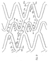
- Figure 3 shows a pattern of a stent according to the present invention.
- This pattem may be constructed of known materials, and for example stainless steel, but it is particularly suitable to be constructed from NiTi.
- the pattern can be formed by etching a flat sheet of NiTi into the pattern shown.
- the flat sheet is formed into a stent by rolling the etched sheet into a tubular shape, and welding the edges of the sheet together to form a tubular stent.
- NiTi stent is heat treated, as known by those skilled in the art, to take advantage of the shape memory characteristics of NiTi and its superelasticity.
- the pattern 300 is formed from a plurality of each of two orthogonal meander patterns which patterns are intertwined with each other.
- the term "meander pattern” is taken herein to describe a periodic pattern about a center line and "orthogonal meander patterns” are patterns whose center lines are orthogonal to each other.
- a meander pattern 301 is a vertical sinusoid having a vertical center line 302.
- a meander pattern 301 has two loops 304 and 306 per period wherein loops 304 open to the right while loops 306 open to the left. Loops 304 and 306 share common members 308 and 310, where member 308 joins one loop 304 to its following loop 306 and member 310 joins one loop 306 to its following loop 304.
- a meander pattern 312 (two of which have been shaded for reference) is a horizontal pattern having a horizontal center line 314.
- a horizontal meander pattern 312 also has loops labeled 316, 318, 320, 322, and between the loops of a period is a section labeled 324.
- Vertical meander pattern 301 is provided in odd and even (o and e) versions which are 180° out of phase with each other.
- each left opening loop 306 of meander pattern 301o faces a right opening loop 304 of meander pattern 301e and a right opening loop 304 of meander pattern 301o faces a left opening loop 306 of meander pattern 301e.
- the horizontal meander pattern 312 is also provided in odd and even forms.
- the straight sections 324 of the horizontal meander pattern 312e intersect with every third common member 310 of the even vertical meander pattern 301e.
- the straight sections 324 of the horizontal meander pattern 312o also intersect with every third common member 310 of the odd vertical meander pattern 301.
- the loops of the vertical meander patterns 301 open up in the vertical direction. This causes them to shorten in the horizontal direction.
- the loops in the horizontal meander pattern 312 open up both in the vertical direction and the horizontal direction, compensating for the shortening of the loops of the vertical meander patterns.
- the horizontal meander pattern 312 in the present invention avoids foreshortening in a self-expanding stent in a particularly effective manner.
- Fig. 14 because of the configuration of the horizontal meander pattern 312, when the stent is compressed from an expanded position to a crimped position, the length of the horizontal meander pattern naturally shrinks. Consequently, when the stent expands, the horizontal meander pattern elongates and compensates for the shortening of the vertical meander pattern as the vertical meander pattern expands.
- a horizontal meander pattern with such shapes as N-shapes will not naturally shrink longitudinally when compressed.
- a stent formed from the pattern of Figure 3 and made ofNiTi is particularly well suited for use in the carotid artery or other lumens subject to an outside pressure.
- One reason is that because the stent is formed of NiTi, it is reboundable, which is a desirable property for stents placed in the carotid artery.
- the other reason is that the stent of Figure 3 offers excellent scaffolding, which is particularly important in the carotid artery. Scaffolding is especially important in the carotid artery because dislodged particles in the artery may embolize and cause a stroke.
- FIG 4 is an expanded view of one flexible cell 500 of the pattern of Figure 3.
- Each flexible cell 500 includes: a first member 501 having a first end 502 and a second end 503; a second member 504 having a first end 505 and a second end 506; a third member 507 having a first end 508 and a second end 509; and a fourth member 510 having a first end 511 and a second end 512.
- the first end 502 of the first member 501 is joined to the first end 505 of the second member 504 by a first curved member 535 to form a first loop 550
- the second end 506 of the second member 504 is joined to the second end 509 of the third member 508 by a second curved member 536
- the first end 508 of the third member 507 is joined to the first end 511 of the fourth member 510 by a third curved member 537 to form a second loop 531.
- the first loop 550 defines a first angle 543.
- the second loop 531 defines a second angle 544.
- Each cell 500 also includes a fifth member 513 having a first end 514 and a second end 515; a sixth member 516 having a first end 517 and a second end 518; a seventh member 519 having a first end 520 and a second end 521; an eighth member 522 having a first end 523 and a second end 524; a ninth member 525 having a first end 526 and a second end 527; and a tenth member having a first end 529 and a second end 530.
- the first end 514 of the fifth member 513 is joined to the second end 503 of the first member 501 at second junction point 542, the second end 515 of the fifth member 513 is joined to the second end 518 of the sixth member by a curved member 539 to form a third loop 532, the first end 517 of the sixth member 516 is joined to the first end 520 of the seventh member 519 by a fifth curved member 548, the second end 521 of the seventh member 519 is joined to the second end 524 of the eighth member 522 at third junction point 540 to form a fourth loop 533, the first end 523 of the eighth member 522 is joined to the first end 526 of the ninth member 525 by a sixth curved member 549, the second end 526 of the ninth member 525 is joined to the second end 530 of the tenth member 528 by a seventh curved member 541 to form a fifth loop 534,-and the first end 529 of the tenth member 528 is joined to the second end 512 of the fourth member
- the first member 501, the third member 507, the sixth member 516, the eighth member 522, and the tenth member 528 have substantially the same angular orientation to the longitudinal axis of the stent and the second member 504, the fourth member 510, the fifth member 513, the seventh member 519, and the ninth member 512 have substantially the same angular orientation to the longitudinal axis of the stent.
- the lengths of the first, second, third and fourth members 501, 504, 507, 510 are substantially equal.
- the lengths of the fifth, sixth, seventh, eighth, ninth and tenth members 513, 516, 519, 522, 525, 528 are also substantially equal.
- Other embodiments where lengths of individual members are tailored for specific applications, materials of construction or methods of delivery are also possible, and may be preferable for them.
- the first, second, third, and fourth members 501, 504, 507, 510 have a width that is greater than the width of the fifth, sixth, seventh, eighth, ninth, and tenth members 513 516 519, 522, 525, 528 in that cell.
- the differing widths of the first, second, third, and fourth members and the fifth, sixth, seventh, eighth, ninth, and tenth members with respect to each other contribute to the overall flexibility and resistance to radial compression of the cell.
- the widths of the various members can be tailored for specific applications.
- the fifth, sixth, seventh, eighth, ninth, and tenth members are optimized predominantly to enable longitudinal flexibility, both before and after expansion, while the first, second, third, and fourth members are optimized predominantly to enable sufficient resistance to radial compression to hold a vessel open.
- specific members are optimized to predominantly enable a desired characteristic, all the portions of the cell interactively cooperate and contribute to the characteristics of the stent.
- Figures 5 and 6 show a pattern and an expanded view of one cell of an embodiment of the present invention which is specially adapted for a stent made of stainless steel.
- the pattern is similar to the pattern of Figures 3 and 4, and the similar reference numerals are used to indicate the generally corresponding parts.
- the second loops 1531 are made stronger by shortening the third and fourth members 1507, 1510. This helps assure that the second loops do not "flare out” during delivery of the stent through tortuous anatomy. This "flaring out” is not a concern with NiTi stents which are covered by a sheath.during delivery.
- the length of the members in this embodiment may be shorter than the length of the corresponding members in the embodiment illustrated in Figures 3 and 4.
- the amount of strain allowed in a self-expanding NiTi stent may be around 10%.
- the amount of strain allowed typically may be 20% or greater. Therefore, to facilitate stents made of NiTi and stents made of stainless steel expanding to comparable diameters, the members of the NiTi stent may be longer than the members of a stainless steel stent.
- Figure 7 illustrates another aspect of the present invention.
- the stent of Figure 7 is also constructed from orthogonal meander patterns 2301, 2302.
- the meander patterns form a series of interlocking cells 50, 700 of two types.
- the first type of cell 50 is taught by U.S. Patent No. 5,733,303. These cells are arranged so that they form alternating bands 704 of first type of cells 50 and bands 706 of the second type of cells 700.
- each of the 303 cells 50 has a first longitudinal apex 100 and a second longitudinal end 78.
- Each cell 50 also is provided with a first longitudinal end 77 and a second longitudinal apex 104 disposed at the second longitudinal end 78.
- Each cell 50 also includes a first member 51 having a longitudinal component having a first end 52 and a second end 53; a second member 54 having a longitudinal component haying a first end 55 and a second end 56; a third member 57 having a longitudinal component having a first end 58 and a second end 59; and a fourth member 60 having a longitudinal component having a first end 61 and a second end 62.
- the stent also includes a first loop or curved member 63 defining a first angle 64 disposed between the first end 52 of the first member 51 and the first end 55 of the second member 54.
- a second loop or curved member 65 defining a second angle 66 is disposed between the second end 59 of the third member 57 and the second end 62 of the fourth member 60 and is disposed generally opposite to the first loop 63.
- a first flexible compensating member (or a section of a longitudinal meander pattern) 67 having curved portion and two legs with a first end 68 and a second end 69 is disposed between the first member 51 and the third member 57 with the first end 68 of the first flexible compensating member 67 joined to and communicating with the second end 53 of the first member 51 and the second end 69 of the first flexible compensating member 67 joined to and communicating with the first end 58 of the third member 57.
- the first end 68 and the second end 69 are disposed a variable longitudinal distance 70 from each other.
- a second flexible compensating member (or, a section of a longitudinal meander pattern) 71 having a first end 72 and a second end 73 is disposed between the second member 54 and the fourth member 60.
- the first end 72 of the second flexible compensating member 71 is joined to and communicates with the second end 56 of the second member 54 and the second end 73 of the second flexible compensating member 71 is joined to and communicates with the first end 61 of the fourth member 60.
- the first end 72 and the second end 73 are disposed a variable longitudinal distance 74 from each other.
- the first and second flexible compensating members, and particularly the curved portion thereof, 67 and 71 are arcuate.
- each flexible compensating member 67a, 71a includes: a first portion or leg 79 with a first end 80 and a second end 81; a second portion or leg 82 with a first end 83 and a second end 84; and a third portion or leg 85 with the first end 86 and a second end 87, with the second end 81 and the second end 84 being joined by a curved member and the first end 83 and the first end 86 being joined by a curved member.
- the first end of a flexible compensating member 67a, 71a is the same as the first end 80 of the first portion 79, and the second end of a flexible compensating member 67a, 71a is the same as the second end 87 of the third portion 85.
- a first area of inflection 88 is disposed between the second end 81 of the first portion 79 and the second end 84 of the second portion 82 where the curved portion joining them lies.
- a second area of inflection 89 is disposed between the first end 83 of the second portion 82 and the first end 86 of the third portion 85 where the curved portion joining them lies.
- Figure 7 illustrates a pattern of alternating bands of cells
- the stent may be optimized for a particular usage by tailoring the configuration of the bands.
- the middle band of the second type of cells 700 may instead be formed of cells 50, or vice versa.
- the second type of cells in Figure 7 may also utilize the cell configurations described with respect to Figures 4 and 6.
- the cell configurations of Figures 4 and 6 provide the advantage that they will not cause any torque of one portion of the cell relative to another portion of the cell about the longitudinal axis of the stent upon expansion, which may happen when the second type of cells 700 expand, a torque which could cause a stent to deform, and stick out.
- all of the flexible compensating members are arranged so that the path of the flexible compensating members, from left to right, travels in a generally downward direction.
- the cells 700 can also be arranged so that the flexible compensating members in one band are arranged in a generally upward direction, and the flexible compensating members in an adjacent band are arranged in a generally downward direction.
- One skilled in the art can easily make these modifications.
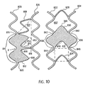
- Figure 10 is a schematic representation comparing the cells 804 of the present invention, which have three points where the intertwined first and second meander patterns meet and are in that sense three cornered or triangular cells, with cells 802 of the '303 stent which have four points where the intertwined first and second meander patterns meet and are in that sense four cornered or square cells. More particularly, on the left side of Figure 10, a pair of vertical meander patterns 806, 826 are joined by members 808, 810, 812 (which are sections of longitudinal meander patterns) to form a plurality of three cornered or triangular cells 804.
- triangular cell it is meant that there are three sections 810, 812, 814, each having loop portions and three associated points 816, 818, 820 of their joining, forming each cell.
- a pair of vertical meander patterns 822, 824 are joined together compensating members 828, 830, 832, 834 (which are sections of a longitudinal meander) to form a plurality of square cells 804.
- square cell it is meant that there are four sections, each having loop portions, and four associated points of their joining, forming each cell.
- the shaded cell 802 is formed from four sections 832, 836, 830, 838, with four associated points of their joining 840, 842, 844, 846.
- Both the square cell and the triangular cell have two kinds of sections with loops.
- the first kind of loop containing section is formed from a vertical meander pattern and is optimized predominantly to enable radial support.
- the second kind of loop containing section is optimized predominantly to enable flexibility along the longitudinal axis of the stent.
- each loop containing section is optimized predominantly to enable a desired characteristic of the stent, the sections are interconnected and cooperate to define the characteristics of the stent. Therefore, the first kind of loop containing section contributes to the longitudinal flexibility of the stent, and the second kind of loop containing section contributes to the radial support of the stent.
- the second kind of loop containing sections 830, 832 each have one inflection point 848, 850.
- the loop containing sections 810, 812 each have two inflection point areas 852, 854, 856, 858.
- the higher number of inflection points allows more freedom to deform after expansion of the stent and distributes the deformation over a longer section, thus, reducing the maximal strain along these loop containing sections.
- a square cell 802 is generally more elongated along the longitudinal axis of the stent than a triangular cell 804, which is generally more elongated along the circumference of the stent. This also contributes to higher flexibility after expansion.
- the area of a triangular cell 804 is the same as a square cell 802. This can be more readily understood with reference to a band of cells around the circumference of a stent. Each band will encompass the same area, and each band will have the same number of cells. Accordingly, the area of each cell in one band formed of square cells will be the same as the area of each cell in another band formed of triangular cells.
- a triangular cell offers increased coverage of a vessel wall.
- the stent is substantially uniform over its entire length.
- a band of cells 850a may be designed to provide different flexibility characteristics or different radial compression characteristics than the remaining bands of cells by altering the widths and lengths of the members making up that band.
- the stent may be adapted to provide increased access to a side branch lumen by providing at least one cell 852a which is larger in size then the remaining cells, or by providing an entire band of cells 854a which are larger in size than the other bands of cells.
- the stent may be designed to expand to different diameters along the length of the stent.
- the stent may also be treated after formation of the stent by coating the stent with a medicine, plating the stent with a protective material, plating the stent with a radiopaque material, or covering the stent with a material.
- Figures 12 and 13 show alternative patterns for a stent constructed according to the principles of the present invention.
- the stent shown in Fig. 12 has two bands of cells 856a located at each of the proximal end 860 and distal end 862.
- the cells that form the bands of cells 856a located at the ends of the stent are 303 type cells.
- the remaining cells in the stent are the same as described with respect to the cells 500 depicted in Fig. 6.
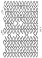
- the stent shown in Fig. 13 has alternating bands of cells 864, 866, 868.
- the first type of band of cells 864 is composed of '303 type cells.
- the second and third types of bands of cells 866, 868 are formed of the cells described with respect to the cells 500 depicted in Fig. 4.
- any various combination of cells may be used in the present invention.
- a longitudinally flexible stent that utilizes a closed cell structure to provide excellent coverage of the vessel wall.
- the general concepts described herein can be utilized to form stents with different configurations than the particular embodiments described herein.
- the general concepts can be used to form bifurcated stents. It will be appreciated by persons skilled in the art that the present invention is not limited to what has been particularly shown and described above. Rather, the scope of the present invention is defined by the claims which follow.
Landscapes
- Health & Medical Sciences (AREA)
- Engineering & Computer Science (AREA)
- Biomedical Technology (AREA)
- Heart & Thoracic Surgery (AREA)
- Life Sciences & Earth Sciences (AREA)
- Cardiology (AREA)
- Oral & Maxillofacial Surgery (AREA)
- Transplantation (AREA)
- Physics & Mathematics (AREA)
- Vascular Medicine (AREA)
- Optics & Photonics (AREA)
- Animal Behavior & Ethology (AREA)
- General Health & Medical Sciences (AREA)
- Public Health (AREA)
- Veterinary Medicine (AREA)
- Prostheses (AREA)
- Media Introduction/Drainage Providing Device (AREA)
- Materials For Medical Uses (AREA)
- Apparatus Associated With Microorganisms And Enzymes (AREA)
Description
- The present invention relates generally to stents, which are endoprostheses implanted into vessels within the body, such as blood vessels, to support and hold open the vessels, or to secure and support other endoprostheses in the vessels. In particular, the present invention relates to a stent which is longitudinally flexible before and after expansion.
- Various stents are known in the art. Typically stents are generally tubular in shape, and are expandable from a relatively small, unexpanded diameter to a larger, expanded diameter. For implantation, the stent is typically mounted on the end of a catheter, with the stent being held on the catheter at its relatively small, unexpanded diameter. By the catheter, the unexpanded stent is directed through the lumen to the intended implantation site. Once the stent is at the intended implantation site, it is expanded, typically either by an internal force, for example by inflating a balloon on the inside of the stent, or by allowing the stent to self-expand, for example by removing a sleeve from around a self-expanding stent, allowing the stent to expand outwardly. In either case, the expanded stent resists the tendency of the vessel to narrow, thereby maintaining the vessel's patency.
- U.S. Patent No. 5,733,303 to Israel et al. (" ' 303") shows a unique stent formed of a tube having a patterned shape which has first and second meander patterns having axes extending in first and second directions. The second meander patterns are intertwined with the first meander patterns to form flexible cells. Stents such as this one are very flexible in their unexpanded state such that they can be tracked easily down tortuous lumens. Upon expansion, these stents provide excellent radial support, stability, and coverage of the vessel wall. These stents are also conformable, in that they adapt to the shape of the vessel wall during implantation.
- One feature of stents with a cellular mesh design such as this one, however, is that they have limited longitudinal flexibility after expansion, which may be a disadvantage in particular applications. This limited longitudinal flexibility may cause stress points at the end of the stent and along the length of the stent. Conventional mesh stents like that shown in U.S. Patent 4,733,665 may simply lack longitudinal flexibility, which is illustrated by Figure 1, a schematic diagram of a
conventional stent 202 in acurved vessel 204. - To implant a stent, it may be delivered to a desired site by a balloon catheter when the stent is in an unexpanded state. The balloon catheter is then inflated to expand the stent, affixing the stent into place. Due to the high inflation pressures of the balloon -- up to 20 atmthe balloon causes the
curved vessel 204 and even a longitudinally flexible stent to straighten when it is inflated. If the stent, because of the configuration of its mesh is or becomes relatively rigid after expansion, then the stent remains or tends to remain in the same or substantially the same shape after deflation of the balloon. However, the artery attempts to return to its natural curve (indicated by dashed lines) in Figure 1 with reference to a conventional mesh stent. The mismatch between the natural curve of the artery and the straightened section of the artery with a stent may cause points ofstress concentration 206 at the ends of the stent and stress along the entire stent length. The coronary vasculature can impose additional stress on stents because the coronary vasculature moves relatively significant amounts with each heartbeat. For illustration purposes, the difference between the curve of the vessel and the straightened stent has been exaggerated in Figure 1. - U.S. Patent No. 5,807,404 to Richter shows another stent which is especially suited for implantation into curved arterial portions or ostial regions. This stent can include sections adjacent the end of the stent with greater bending flexibility than the remaining axial length of the stent. While this modification at the end of the stent alleviates the stress at the end points, it does not eliminate the stress along the entire length of the stent.
- Various stents are known that retain longitudinal flexibility after expansion. For example, U.S. Patent Nos. 4,886,062 and 5,133,732 to Wiktor ("the Wiktor '062 and '732 patents") show various stents formed of wire wherein the wire is initially formed into a band of zigzags forming a serpentine pattern, and then the zig-zag band is coiled into a helical stent. The stents are expanded by an internal force, for example by inflating a balloon.
- The coiled zig-zag stents that are illustrated in Figures 1 through 6 of the Wiktor '062 and '732 patents are longitudinally flexible both in the expanded and unexpanded condition such that they can be tracked easily down tortuous lumens and such that they conform relatively closely to the compliance of the vessel after deployment. While these stents are flexible, they also have relatively unstable support after expansion. Furthermore, these stents leave large portions of the vessel wall uncovered, allowing tissue and plaque prolapse into the lumen of the vessel.
- Thus, it is desired to have a stent which exhibits longitudinal flexibility before expansion such that it can easily be tracked down tortuous lumens and longitudinal flexibility after expansion such that it can comply with the vessel's natural flexibility and curvature while still providing continuous, stable coverage of a vessel wall that will minimize tissue sag into the lumen.
- Accordingly, an object of the invention is to provide a stent that is longitudinally flexible before expansion so that it can easily be tracked down tortuous vessels and remains longitudinally flexible after expansion such that it will substantially eliminate any stress points by complying with the vessel's flexibility and assuming the natural curve of the vessel.
- Another object of the present invention is to provide a stent that is longitudinally flexible after delivery such that it flexes during the cycles of the heartbeat to reduce cyclic stress at the ends of the stent and along the stent.
- Another object of the present invention is to provide a stent with a closed cell pattern such that it provides good coverage and support to a vessel wall after expansion.
- Other advantages of the present invention will be apparent to those skilled in the art.
- In accordance with these objects, the stent of the present invention is formed to be a tube having a patterned shape which has first and second meander patterns having axes extending in first and second direction wherein the second meander patterns are intertwined with the first meander patterns.
- In accordance with the invention, the intertwined meander patterns form cells which have three points at which the first and second meander patterns meet each other, and which in this sense could be called triangular cells. These three cornered or triangular cells are flexible about the longitudinal axis of the stent after expansion. The triangular cells have three sections with loop portions therein and being joined to one another at only three associated points of their joining, and wherein the second loop containing section forms two loops opening towards the interior of the cell. These triangular cells provide comparable scaffolding and radial strength to that of cells formed by intertwined meander patterns which have four points at which the first and second patterns meet each other, and which in this sense could be called square cells.
- In another embodiment of the invention, bands of cells are provided along the length of a stent. The bands of cells alternate between cells adapted predominantly to enhance radial support with cells that are adapted predominantly to enhance longitudinal flexibility after expansion.
- In another embodiment of the invention, the first meander patterns are adapted to prevent any "flaring out" of loops of the first meander patterns during delivery of the stent.
- A stent according to the invention retains the longitudinal flexibility associated with the '303 cellular stent in its unexpanded state, and has increased longitudinal flexibility in the expanded state. The stent does so without sacrificing scaffolding -- i.e. coverage of the vessel wall -- or radial support.
-
- Figure 1
- shows a schematic diagram of a conventional rigid stent deployed in a curved lumen;
- Figure 2
- shows a schematic diagram of a stent of the present invention deployed in a curved lumen;
- Figure 3
- shows a pattern for a stent made in accordance with the present invention;
- Figure 4
- shows an enlarged view of one cell of the pattern of Figure 3;
- Figure 5
- shows a pattern for a stent made in accordance with the present invention;
- Figure 6
- shows an enlarged view of one cell of the pattern of Figure 5;
- Figure 7
- shows a pattern for a stent made not in accordance with the present invention;
- Figure 8
- shows an enlarged view of one cell used in the pattern of Figure 7;
- Figure 9
- shows an enlarged view of another cell used in Figure 7;
- Figure 10
- shows a schematic comparison of a four cornered or "square cell" and a three cornered or "triangular" cell of the present invention;
- Figure 11
- shows a pattern for a stent constructed according to the principles of the invention which has variable geometry along its length;
- Figure 12
- shows another pattern for a stent constructed according to the principles of the invention;
- Figure 13
- shows another pattern for a stent constructed according to the principles of the invention;
- Figure 14
- shows the elongation of a portion of a horizontal meander pattern formed of NiTi.
- Figure 2 shows a schematic diagram of a longitudinally
flexible stent 208 of the present invention. Thestent 208 may be delivered to acurved vessel 210 by a balloon catheter, and implanted in the artery by inflating the balloon. As described before, the balloon causes the artery to straighten upon inflation of the balloon. However, upon deflation of the balloon, thestent 208 assumes the natural curve of thevessel 210 because it is and remains longitudinally flexible after expansion. This reduces any potential stress points at the ends of the stent and along the length of the stent. Furthermore, because the stent is longitudinally flexible after expansion, the stent will flex longitudinally with the vessel during the cycles caused by a heartbeat. This also reduces any cyclic stress at the ends of the stent and along the length of the stent. - Figure 3 shows a pattern of a stent according to the present invention. This pattem may be constructed of known materials, and for example stainless steel, but it is particularly suitable to be constructed from NiTi. The pattern can be formed by etching a flat sheet of NiTi into the pattern shown. The flat sheet is formed into a stent by rolling the etched sheet into a tubular shape, and welding the edges of the sheet together to form a tubular stent. The details of this method of forming the stent, which has certain advantages, are disclosed in U.S. Patent Nos. 5,836,964 and 5,997,973. Other methods known to those of skill in the art such as laser cutting a tube or etching a tube may also be used to construct a stent which uses the present invention. After formation into a tubular shape, a NiTi stent is heat treated, as known by those skilled in the art, to take advantage of the shape memory characteristics of NiTi and its superelasticity.
- The
pattern 300 is formed from a plurality of each of two orthogonal meander patterns which patterns are intertwined with each other. The term "meander pattern" is taken herein to describe a periodic pattern about a center line and "orthogonal meander patterns" are patterns whose center lines are orthogonal to each other. - A meander pattern 301 is a vertical sinusoid having a
vertical center line 302. A meander pattern 301 has twoloops loops 304 open to the right whileloops 306 open to the left.Loops common members 308 and 310, where member 308 joins oneloop 304 to its followingloop 306 andmember 310 joins oneloop 306 to its followingloop 304. - A meander pattern 312 (two of which have been shaded for reference) is a horizontal pattern having a
horizontal center line 314. A horizontal meander pattern 312 also has loops labeled 316, 318, 320, 322, and between the loops of a period is a section labeled 324. - Vertical meander pattern 301 is provided in odd and even (o and e) versions which are 180° out of phase with each other. Thus, each
left opening loop 306 of meander pattern 301o faces aright opening loop 304 ofmeander pattern 301e and aright opening loop 304 of meander pattern 301o faces aleft opening loop 306 ofmeander pattern 301e. - The horizontal meander pattern 312 is also provided in odd and even forms. The
straight sections 324 of thehorizontal meander pattern 312e intersect with every thirdcommon member 310 of the evenvertical meander pattern 301e. Thestraight sections 324 of the horizontal meander pattern 312o also intersect with every thirdcommon member 310 of the odd vertical meander pattern 301. - Upon expansion of the stent, the loops of the vertical meander patterns 301 open up in the vertical direction. This causes them to shorten in the horizontal direction. The loops in the horizontal meander pattern 312 open up both in the vertical direction and the horizontal direction, compensating for the shortening of the loops of the vertical meander patterns.
- It should be noted that the horizontal meander pattern 312 in the present invention avoids foreshortening in a self-expanding stent in a particularly effective manner. As shown in Fig. 14, because of the configuration of the horizontal meander pattern 312, when the stent is compressed from an expanded position to a crimped position, the length of the horizontal meander pattern naturally shrinks. Consequently, when the stent expands, the horizontal meander pattern elongates and compensates for the shortening of the vertical meander pattern as the vertical meander pattern expands. In contrast, a horizontal meander pattern with such shapes as N-shapes will not naturally shrink longitudinally when compressed.
- A stent formed from the pattern of Figure 3 and made ofNiTi is particularly well suited for use in the carotid artery or other lumens subject to an outside pressure. One reason is that because the stent is formed of NiTi, it is reboundable, which is a desirable property for stents placed in the carotid artery. The other reason is that the stent of Figure 3 offers excellent scaffolding, which is particularly important in the carotid artery. Scaffolding is especially important in the carotid artery because dislodged particles in the artery may embolize and cause a stroke.
- Figure 4 is an expanded view of one
flexible cell 500 of the pattern of Figure 3. Eachflexible cell 500 includes: afirst member 501 having afirst end 502 and asecond end 503; asecond member 504 having afirst end 505 and asecond end 506; athird member 507 having afirst end 508 and asecond end 509; and afourth member 510 having afirst end 511 and asecond end 512. Thefirst end 502 of thefirst member 501 is joined to thefirst end 505 of thesecond member 504 by a first curved member 535 to form afirst loop 550, thesecond end 506 of thesecond member 504 is joined to thesecond end 509 of thethird member 508 by a second curved member 536, and thefirst end 508 of thethird member 507 is joined to thefirst end 511 of thefourth member 510 by a thirdcurved member 537 to form asecond loop 531. Thefirst loop 550 defines afirst angle 543. Thesecond loop 531 defines asecond angle 544. Eachcell 500 also includes afifth member 513 having afirst end 514 and asecond end 515; a sixth member 516 having a first end 517 and a second end 518; aseventh member 519 having afirst end 520 and asecond end 521; aneighth member 522 having afirst end 523 and asecond end 524; aninth member 525 having afirst end 526 and asecond end 527; and a tenth member having afirst end 529 and asecond end 530. Thefirst end 514 of thefifth member 513 is joined to thesecond end 503 of thefirst member 501 atsecond junction point 542, thesecond end 515 of thefifth member 513 is joined to the second end 518 of the sixth member by acurved member 539 to form athird loop 532, the first end 517 of the sixth member 516 is joined to thefirst end 520 of theseventh member 519 by a fifth curved member 548, thesecond end 521 of theseventh member 519 is joined to thesecond end 524 of theeighth member 522 atthird junction point 540 to form afourth loop 533, thefirst end 523 of theeighth member 522 is joined to thefirst end 526 of theninth member 525 by a sixthcurved member 549, thesecond end 526 of theninth member 525 is joined to thesecond end 530 of thetenth member 528 by a seventhcurved member 541 to form afifth loop 534,-and thefirst end 529 of thetenth member 528 is joined to thesecond end 512 of thefourth member 510. Thethird loop 532 defines athird angle 545. Thefourth loop 533 defines afourth angle 546. Thefifth loop 534 defines afifth angle 547. - In the embodiment shown in Fig. 4, the
first member 501, thethird member 507, the sixth member 516, theeighth member 522, and thetenth member 528 have substantially the same angular orientation to the longitudinal axis of the stent and thesecond member 504, thefourth member 510, thefifth member 513, theseventh member 519, and theninth member 512 have substantially the same angular orientation to the longitudinal axis of the stent. In the embodiment shown in Figure 4, the lengths of the first, second, third andfourth members tenth members - Preferably, the first, second, third, and
fourth members tenth members 513 516 519, 522, 525, 528 in that cell. The differing widths of the first, second, third, and fourth members and the fifth, sixth, seventh, eighth, ninth, and tenth members with respect to each other contribute to the overall flexibility and resistance to radial compression of the cell. The widths of the various members can be tailored for specific applications. Preferably, the fifth, sixth, seventh, eighth, ninth, and tenth members are optimized predominantly to enable longitudinal flexibility, both before and after expansion, while the first, second, third, and fourth members are optimized predominantly to enable sufficient resistance to radial compression to hold a vessel open. Although specific members are optimized to predominantly enable a desired characteristic, all the portions of the cell interactively cooperate and contribute to the characteristics of the stent. - Figures 5 and 6 show a pattern and an expanded view of one cell of an embodiment of the present invention which is specially adapted for a stent made of stainless steel. The pattern is similar to the pattern of Figures 3 and 4, and the similar reference numerals are used to indicate the generally corresponding parts.
- In this embodiment of the invention, for example, the
second loops 1531 are made stronger by shortening the third andfourth members - Furthermore, the length of the members in this embodiment may be shorter than the length of the corresponding members in the embodiment illustrated in Figures 3 and 4. Typically, the amount of strain allowed in a self-expanding NiTi stent may be around 10%. In a stainless steel stent, the amount of strain allowed typically may be 20% or greater. Therefore, to facilitate stents made of NiTi and stents made of stainless steel expanding to comparable diameters, the members of the NiTi stent may be longer than the members of a stainless steel stent.
- Figure 7 illustrates another aspect of the present invention. The stent of Figure 7 is also constructed from
orthogonal meander patterns 2301, 2302. The meander patterns form a series of interlockingcells cell 50 is taught by U.S. Patent No. 5,733,303. These cells are arranged so that they form alternatingbands 704 of first type ofcells 50 andbands 706 of the second type ofcells 700. - As seen in Figure 8 and particularly with respect to the cell labeled for ease of description, each of the 303
cells 50 has a firstlongitudinal apex 100 and a secondlongitudinal end 78. Eachcell 50 also is provided with a firstlongitudinal end 77 and a secondlongitudinal apex 104 disposed at the secondlongitudinal end 78. Eachcell 50 also includes afirst member 51 having a longitudinal component having afirst end 52 and asecond end 53; asecond member 54 having a longitudinal component haying afirst end 55 and asecond end 56; athird member 57 having a longitudinal component having afirst end 58 and asecond end 59; and afourth member 60 having a longitudinal component having afirst end 61 and asecond end 62. The stent also includes a first loop orcurved member 63 defining afirst angle 64 disposed between thefirst end 52 of thefirst member 51 and thefirst end 55 of thesecond member 54. A second loop orcurved member 65 defining a second angle 66 is disposed between thesecond end 59 of thethird member 57 and thesecond end 62 of thefourth member 60 and is disposed generally opposite to thefirst loop 63. A first flexible compensating member (or a section of a longitudinal meander pattern) 67 having curved portion and two legs with afirst end 68 and asecond end 69 is disposed between thefirst member 51 and thethird member 57 with thefirst end 68 of the first flexible compensatingmember 67 joined to and communicating with thesecond end 53 of thefirst member 51 and thesecond end 69 of the first flexible compensatingmember 67 joined to and communicating with thefirst end 58 of thethird member 57. Thefirst end 68 and thesecond end 69 are disposed a variablelongitudinal distance 70 from each other. A second flexible compensating member (or, a section of a longitudinal meander pattern) 71 having afirst end 72 and asecond end 73 is disposed between thesecond member 54 and thefourth member 60. Thefirst end 72 of the second flexible compensatingmember 71 is joined to and communicates with thesecond end 56 of thesecond member 54 and thesecond end 73 of the second flexible compensatingmember 71 is joined to and communicates with thefirst end 61 of thefourth member 60. Thefirst end 72 and thesecond end 73 are disposed a variablelongitudinal distance 74 from each other. In this embodiment, the first and second flexible compensating members, and particularly the curved portion thereof, 67 and 71 are arcuate. - The second type of
cell 700 is illustrated in Figure 9 and the same reference numerals with an added "a" are used to indicate generally corresponding areas of the cell. The apices 100a, 104a of the second type ofcell 700 are offset circumferentially. Also, each flexible compensatingmember 67a, 71a includes: a first portion orleg 79 with afirst end 80 and asecond end 81; a second portion orleg 82 with afirst end 83 and asecond end 84; and a third portion orleg 85 with thefirst end 86 and asecond end 87, with thesecond end 81 and thesecond end 84 being joined by a curved member and thefirst end 83 and thefirst end 86 being joined by a curved member. The first end of a flexible compensatingmember 67a, 71a is the same as thefirst end 80 of thefirst portion 79, and the second end of a flexible compensatingmember 67a, 71a is the same as thesecond end 87 of thethird portion 85. A first area ofinflection 88 is disposed between thesecond end 81 of thefirst portion 79 and thesecond end 84 of thesecond portion 82 where the curved portion joining them lies. A second area ofinflection 89 is disposed between thefirst end 83 of thesecond portion 82 and thefirst end 86 of thethird portion 85 where the curved portion joining them lies. - While Figure 7 illustrates a pattern of alternating bands of cells, the stent may be optimized for a particular usage by tailoring the configuration of the bands. For example, the middle band of the second type of
cells 700 may instead be formed ofcells 50, or vice versa. The second type of cells in Figure 7 may also utilize the cell configurations described with respect to Figures 4 and 6. The cell configurations of Figures 4 and 6 provide the advantage that they will not cause any torque of one portion of the cell relative to another portion of the cell about the longitudinal axis of the stent upon expansion, which may happen when the second type ofcells 700 expand, a torque which could cause a stent to deform, and stick out. - As illustrated in Figure 7, all of the flexible compensating members are arranged so that the path of the flexible compensating members, from left to right, travels in a generally downward direction. The
cells 700 can also be arranged so that the flexible compensating members in one band are arranged in a generally upward direction, and the flexible compensating members in an adjacent band are arranged in a generally downward direction. One skilled in the art can easily make these modifications. - Figure 10 is a schematic representation comparing the
cells 804 of the present invention, which have three points where the intertwined first and second meander patterns meet and are in that sense three cornered or triangular cells, withcells 802 of the '303 stent which have four points where the intertwined first and second meander patterns meet and are in that sense four cornered or square cells. More particularly, on the left side of Figure 10, a pair ofvertical meander patterns members triangular cells 804. By triangular cell, it is meant that there are threesections points - On the right side of Figure 10, a pair of
vertical meander patterns members square cells 804. By square cell, it is meant that there are four sections, each having loop portions, and four associated points of their joining, forming each cell. For example, theshaded cell 802 is formed from foursections - Both the square cell and the triangular cell have two kinds of sections with loops. The first kind of loop containing section is formed from a vertical meander pattern and is optimized predominantly to enable radial support. The second kind of loop containing section is optimized predominantly to enable flexibility along the longitudinal axis of the stent. Although each loop containing section is optimized predominantly to enable a desired characteristic of the stent, the sections are interconnected and cooperate to define the characteristics of the stent. Therefore, the first kind of loop containing section contributes to the longitudinal flexibility of the stent, and the second kind of loop containing section contributes to the radial support of the stent.
- In the
square cell 802, it can be seen that the second kind ofloop containing sections inflection point loop containing sections inflection point areas - Furthermore, it can be seen that a
square cell 802 is generally more elongated along the longitudinal axis of the stent than atriangular cell 804, which is generally more elongated along the circumference of the stent. This also contributes to higher flexibility after expansion. - If the
first meander patterns triangular cell 804 is the same as asquare cell 802. This can be more readily understood with reference to a band of cells around the circumference of a stent. Each band will encompass the same area, and each band will have the same number of cells. Accordingly, the area of each cell in one band formed of square cells will be the same as the area of each cell in another band formed of triangular cells. - Although the areas of the cells are equal, the perimeter of the triangular cell is larger than the perimeter of the square cell. Therefore, in comparison to a square cell, a triangular cell offers increased coverage of a vessel wall.
- In the particular embodiments described above, the stent is substantially uniform over its entire length. However, other applications where portions of the stent are adapted to provide different characteristics are also possible. For example, as shown in Figure 11, a band of cells 850a may be designed to provide different flexibility characteristics or different radial compression characteristics than the remaining bands of cells by altering the widths and lengths of the members making up that band. Or, the stent may be adapted to provide increased access to a side branch lumen by providing at least one
cell 852a which is larger in size then the remaining cells, or by providing an entire band ofcells 854a which are larger in size than the other bands of cells. Or, the stent may be designed to expand to different diameters along the length of the stent. The stent may also be treated after formation of the stent by coating the stent with a medicine, plating the stent with a protective material, plating the stent with a radiopaque material, or covering the stent with a material. - Figures 12 and 13 show alternative patterns for a stent constructed according to the principles of the present invention. The stent shown in Fig. 12 has two bands of
cells 856a located at each of theproximal end 860 anddistal end 862. The cells that form the bands ofcells 856a located at the ends of the stent are 303 type cells. The remaining cells in the stent are the same as described with respect to thecells 500 depicted in Fig. 6. The stent shown in Fig. 13 has alternating bands ofcells cells 864 is composed of '303 type cells. The second and third types of bands ofcells cells 500 depicted in Fig. 4. Of course, any various combination of cells may be used in the present invention. - Thus, what is described is a longitudinally flexible stent that utilizes a closed cell structure to provide excellent coverage of the vessel wall. The general concepts described herein can be utilized to form stents with different configurations than the particular embodiments described herein. For example, the general concepts can be used to form bifurcated stents. It will be appreciated by persons skilled in the art that the present invention is not limited to what has been particularly shown and described above. Rather, the scope of the present invention is defined by the claims which follow.
Claims (13)
- A multicellular stent for holding open a lumen, comprising:a plurality of even and odd vertical meander patterns (301e, 301o, 806, 826), the odd vertical meander patterns (301o, 806) being located between every two even vertical meander patterns (301e, 826) and being out of phase with the even vertical meander patterns (301e, 826),a plurality of even and odd horizontal meander patterns (312e, 312o), the odd horizontal meander patterns (312o) being located between every two even horizontal meander patterns (312e),
wherein the vertical meander patterns (301o, 301e, 806, 826) are intertwined with the horizontal meander patterns (312e, 312o) to form a plurality of triangular cells (500, 804), said triangular cells (500, 804) having three sections (810, 812, 814) with loop portions therein and being joined to one another at only three associated points (816, 818, 820) of their joining and wherein the first loop containing section forms two loops (550, 531) opening toward the interior of the cell (500). - A multicellular stent according to claim 1, wherein the triangular cells (500, 804) are formed by a first loop containing section (814), a second loop containing section (812) connected to the first loop containing section (814), and a third loop containing section (810) connected to the first and second loop containing section (814,812).
- A multicellular stent according to claim 1 or 2, wherein the first loop containing section (814) is formed from a portion of a vertical meander pattern (806).
- A multicellular stent according to one of claims 1 to 3, wherein the second and third loop containing sections (812, 810) are formed from portions of one or more horizontal meander patterns (312e, 312o).
- A multicellular stent according to one of claims 1 to 4, wherein members (501, 504, 507, 510) forming the first loop containing section are wider than members (513, 516, 519, 522, 525, 528) forming the second and third loop containing sections.
- A multicellular stent according to one of claims 1 to 5, wherein the second loop containing section forms one loop (532) facing toward the interior of the cell (500).
- A multicellular stent according to one of claims 1 to 6, wherein the third loop containing section forms one loop (534) facing toward the interior of the cell (500).
- A multicellular stent according to one of claims 1 to 7, wherein the stent is made of stainless steel.
- A multicellular stent according to one of claims 1 to 8, wherein the first loop containing section includes one free loop (531).
- A multicellular stent according to one of claims 1 to to 9, wherein one leg (507) of the free loop is shorter than the other leg (510) of the loop.
- A multicellular stent according to one of claims 1 to 10, wherein the length of the second loop containing section (513, 516, 519) is equal to the length of the third loop containing section (522, 525, 528).
- A multicellular stent according to one of claims 1 to 11, wherein each triangular cell (500, 804) of the stent encompasses the same area.
- A multicellular stent according to one of claims 1 to 12, wherein the width of members forming the second loop containing section (513, 516, 519) and the width of members forming the third loop containing section (522, 525, 528) are the same.
Applications Claiming Priority (5)
| Application Number | Priority Date | Filing Date | Title |
|---|---|---|---|
| US09/516,753 US7141062B1 (en) | 2000-03-01 | 2000-03-01 | Longitudinally flexible stent |
| US516753 | 2000-03-01 | ||
| US20272300P | 2000-05-08 | 2000-05-08 | |
| US202723P | 2000-05-08 | ||
| EP01104468A EP1129673B1 (en) | 2000-03-01 | 2001-02-28 | Longitudinally flexible stent |
Related Parent Applications (2)
| Application Number | Title | Priority Date | Filing Date |
|---|---|---|---|
| EP01104468.2 Division | 2001-02-28 | ||
| EP01104468A Division EP1129673B1 (en) | 2000-03-01 | 2001-02-28 | Longitudinally flexible stent |
Publications (3)
| Publication Number | Publication Date |
|---|---|
| EP1295573A2 EP1295573A2 (en) | 2003-03-26 |
| EP1295573A3 EP1295573A3 (en) | 2003-06-04 |
| EP1295573B1 true EP1295573B1 (en) | 2006-02-08 |
Family
ID=26897967
Family Applications (7)
| Application Number | Title | Priority Date | Filing Date |
|---|---|---|---|
| EP02019617A Expired - Lifetime EP1295574B1 (en) | 2000-03-01 | 2001-02-28 | Longitudinally flexible stent |
| EP01104468A Expired - Lifetime EP1129673B1 (en) | 2000-03-01 | 2001-02-28 | Longitudinally flexible stent |
| EP08001226.3A Expired - Lifetime EP1908437B1 (en) | 2000-03-01 | 2001-02-28 | Longitudinally flexible stent |
| EP10012406.4A Expired - Lifetime EP2311409B1 (en) | 2000-03-01 | 2001-02-28 | Longitudinally flexible stent |
| EP02019616A Expired - Lifetime EP1295573B1 (en) | 2000-03-01 | 2001-02-28 | Longitudinally flexible stent |
| EP02019618A Expired - Lifetime EP1295575B1 (en) | 2000-03-01 | 2001-02-28 | Longitudinally flexible stent |
| EP02019615A Expired - Lifetime EP1295572B1 (en) | 2000-03-01 | 2001-02-28 | Longitudinally flexible stent |
Family Applications Before (4)
| Application Number | Title | Priority Date | Filing Date |
|---|---|---|---|
| EP02019617A Expired - Lifetime EP1295574B1 (en) | 2000-03-01 | 2001-02-28 | Longitudinally flexible stent |
| EP01104468A Expired - Lifetime EP1129673B1 (en) | 2000-03-01 | 2001-02-28 | Longitudinally flexible stent |
| EP08001226.3A Expired - Lifetime EP1908437B1 (en) | 2000-03-01 | 2001-02-28 | Longitudinally flexible stent |
| EP10012406.4A Expired - Lifetime EP2311409B1 (en) | 2000-03-01 | 2001-02-28 | Longitudinally flexible stent |
Family Applications After (2)
| Application Number | Title | Priority Date | Filing Date |
|---|---|---|---|
| EP02019618A Expired - Lifetime EP1295575B1 (en) | 2000-03-01 | 2001-02-28 | Longitudinally flexible stent |
| EP02019615A Expired - Lifetime EP1295572B1 (en) | 2000-03-01 | 2001-02-28 | Longitudinally flexible stent |
Country Status (24)
| Country | Link |
|---|---|
| US (1) | US6709453B2 (en) |
| EP (7) | EP1295574B1 (en) |
| JP (3) | JP4564678B2 (en) |
| CN (1) | CN1331957A (en) |
| AR (1) | AR028226A1 (en) |
| AT (5) | ATE317248T1 (en) |
| AU (2) | AU781346B2 (en) |
| BR (1) | BR0100796A (en) |
| CA (4) | CA2619573C (en) |
| CZ (1) | CZ2001664A3 (en) |
| DE (6) | DE60115304T2 (en) |
| EE (1) | EE200100132A (en) |
| ES (2) | ES2466698T3 (en) |
| GB (5) | GB2396111B (en) |
| HK (1) | HK1036926A1 (en) |
| IL (1) | IL141702A (en) |
| MX (1) | MXPA01002225A (en) |
| NO (1) | NO20011066L (en) |
| NZ (1) | NZ510244A (en) |
| PL (1) | PL346192A1 (en) |
| RU (1) | RU2001105404A (en) |
| SG (1) | SG86458A1 (en) |
| SK (1) | SK2662001A3 (en) |
| WO (1) | WO2001064133A1 (en) |
Cited By (6)
| Publication number | Priority date | Publication date | Assignee | Title |
|---|---|---|---|---|
| US9545263B2 (en) | 2014-06-19 | 2017-01-17 | Limflow Gmbh | Devices and methods for treating lower extremity vasculature |
| US10543308B2 (en) | 2017-04-10 | 2020-01-28 | Limflow Gmbh | Methods for routing a guidewire from a first vessel and through a second vessel in lower extremity vasculature |
| US11116943B2 (en) | 2018-10-09 | 2021-09-14 | Limflow Gmbh | Methods for accessing pedal veins |
| US11446170B2 (en) | 2004-09-08 | 2022-09-20 | Limflow Gmbh | Minimally invasive surgical apparatus and methods |
| US11612397B2 (en) | 2019-11-01 | 2023-03-28 | Limflow Gmbh | Devices and methods for increasing blood perfusion to a distal extremity |
| US12096938B2 (en) | 2023-03-24 | 2024-09-24 | Limflow Gmbh | Devices and methods for increasing blood perfusion to a distal extremity |
Families Citing this family (78)
| Publication number | Priority date | Publication date | Assignee | Title |
|---|---|---|---|---|
| US6896696B2 (en) * | 1998-11-20 | 2005-05-24 | Scimed Life Systems, Inc. | Flexible and expandable stent |
| US7204848B1 (en) | 1995-03-01 | 2007-04-17 | Boston Scientific Scimed, Inc. | Longitudinally flexible expandable stent |
| US6626938B1 (en) * | 2000-11-16 | 2003-09-30 | Cordis Corporation | Stent graft having a pleated graft member |
| US20070219642A1 (en) * | 1998-12-03 | 2007-09-20 | Jacob Richter | Hybrid stent having a fiber or wire backbone |
| US20060178727A1 (en) * | 1998-12-03 | 2006-08-10 | Jacob Richter | Hybrid amorphous metal alloy stent |
| US20060122691A1 (en) | 1998-12-03 | 2006-06-08 | Jacob Richter | Hybrid stent |
| US8382821B2 (en) | 1998-12-03 | 2013-02-26 | Medinol Ltd. | Helical hybrid stent |
| US20050033399A1 (en) * | 1998-12-03 | 2005-02-10 | Jacob Richter | Hybrid stent |
| US7828835B2 (en) | 2000-03-01 | 2010-11-09 | Medinol Ltd. | Longitudinally flexible stent |
| US7621947B2 (en) | 2000-03-01 | 2009-11-24 | Medinol, Ltd. | Longitudinally flexible stent |
| US7758627B2 (en) | 2000-03-01 | 2010-07-20 | Medinol, Ltd. | Longitudinally flexible stent |
| US7141062B1 (en) | 2000-03-01 | 2006-11-28 | Medinol, Ltd. | Longitudinally flexible stent |
| US6723119B2 (en) * | 2000-03-01 | 2004-04-20 | Medinol Ltd. | Longitudinally flexible stent |
| US8202312B2 (en) | 2000-03-01 | 2012-06-19 | Medinol Ltd. | Longitudinally flexible stent |
| US8920487B1 (en) | 2000-03-01 | 2014-12-30 | Medinol Ltd. | Longitudinally flexible stent |
| US8496699B2 (en) | 2000-03-01 | 2013-07-30 | Medinol Ltd. | Longitudinally flexible stent |
| US8070792B2 (en) | 2000-09-22 | 2011-12-06 | Boston Scientific Scimed, Inc. | Stent |
| SG108867A1 (en) * | 2001-09-06 | 2005-02-28 | Medinol Ltd | Self articulating stent |
| JP2005501651A (en) * | 2001-09-10 | 2005-01-20 | メディノール リミテッド | Longitudinal flexible stent [Related application] This application is a continuation-in-part of application No. 09 / 864,389, filed on May 25, 2001, and is filed on February 28, 2001. No. 09 / 795,794, a continuation-in-part application, which is an application of application No. 09 / 516,753 filed on Mar. 1, 2000. Claims priority of provisional application 60 / 202,723 of monthly application. |
| US7351256B2 (en) | 2002-05-10 | 2008-04-01 | Cordis Corporation | Frame based unidirectional flow prosthetic implant |
| US7025777B2 (en) * | 2002-07-31 | 2006-04-11 | Unison Therapeutics, Inc. | Flexible and conformable stent and method of forming same |
| US20040054398A1 (en) * | 2002-09-13 | 2004-03-18 | Cully Edward H. | Stent device with multiple helix construction |
| EP1549254A4 (en) * | 2002-09-27 | 2007-11-07 | Medlogics Device Corp | Implantable stent with modified ends |
| US7637942B2 (en) | 2002-11-05 | 2009-12-29 | Merit Medical Systems, Inc. | Coated stent with geometry determinated functionality and method of making the same |
| US7875068B2 (en) | 2002-11-05 | 2011-01-25 | Merit Medical Systems, Inc. | Removable biliary stent |
| US7959671B2 (en) * | 2002-11-05 | 2011-06-14 | Merit Medical Systems, Inc. | Differential covering and coating methods |
| US8105373B2 (en) | 2002-12-16 | 2012-01-31 | Boston Scientific Scimed, Inc. | Flexible stent with improved axial strength |
| US20080051866A1 (en) * | 2003-02-26 | 2008-02-28 | Chao Chin Chen | Drug delivery devices and methods |
| US20040167610A1 (en) * | 2003-02-26 | 2004-08-26 | Fleming James A. | Locking stent |
| US20040249442A1 (en) * | 2003-02-26 | 2004-12-09 | Fleming James A. | Locking stent having multiple locking points |
| US9039755B2 (en) | 2003-06-27 | 2015-05-26 | Medinol Ltd. | Helical hybrid stent |
| US9155639B2 (en) * | 2009-04-22 | 2015-10-13 | Medinol Ltd. | Helical hybrid stent |
| US7316711B2 (en) | 2003-10-29 | 2008-01-08 | Medtronic Vascular, Inc. | Intralumenal stent device for use in body lumens of various diameters |
| US7090694B1 (en) * | 2003-11-19 | 2006-08-15 | Advanced Cardiovascular Systems, Inc. | Portal design for stent for treating bifurcated vessels |
| JP4740740B2 (en) | 2003-12-09 | 2011-08-03 | 大日本住友製薬株式会社 | Drug-containing particles and solid preparation containing the particles |
| US7763064B2 (en) | 2004-06-08 | 2010-07-27 | Medinol, Ltd. | Stent having struts with reverse direction curvature |
| US7887579B2 (en) * | 2004-09-29 | 2011-02-15 | Merit Medical Systems, Inc. | Active stent |
| EP3613387B1 (en) * | 2005-04-04 | 2023-01-11 | Flexible Stenting Solutions, Inc. | Flexible stent |
| US8961585B2 (en) * | 2005-04-25 | 2015-02-24 | Covidien Lp | Controlled fracture connections for stents |
| US20060248698A1 (en) * | 2005-05-05 | 2006-11-09 | Hanson Brian J | Tubular stent and methods of making the same |
| US7731654B2 (en) * | 2005-05-13 | 2010-06-08 | Merit Medical Systems, Inc. | Delivery device with viewing window and associated method |
| US8043358B2 (en) * | 2006-03-29 | 2011-10-25 | Boston Scientific Scimed, Inc. | Stent with overlap and high extension |
| US8348991B2 (en) * | 2006-03-29 | 2013-01-08 | Boston Scientific Scimed, Inc. | Stent with overlap and high expansion |
| EP2020956A2 (en) * | 2006-05-26 | 2009-02-11 | Nanyang Technological University | Implantable article, method of forming same and method for reducing thrombogenicity |
| US8211163B2 (en) * | 2006-09-13 | 2012-07-03 | Boston Scientific Scimed, Inc. | Hybrid symmetrical stent designs |
| US7988723B2 (en) | 2007-08-02 | 2011-08-02 | Flexible Stenting Solutions, Inc. | Flexible stent |
| US8206636B2 (en) | 2008-06-20 | 2012-06-26 | Amaranth Medical Pte. | Stent fabrication via tubular casting processes |
| US10898620B2 (en) | 2008-06-20 | 2021-01-26 | Razmodics Llc | Composite stent having multi-axial flexibility and method of manufacture thereof |
| US8206635B2 (en) | 2008-06-20 | 2012-06-26 | Amaranth Medical Pte. | Stent fabrication via tubular casting processes |
| US9149376B2 (en) | 2008-10-06 | 2015-10-06 | Cordis Corporation | Reconstrainable stent delivery system |
| GB2467097B (en) * | 2008-11-06 | 2011-01-12 | Cook William Europ | Stent member |
| WO2010065241A1 (en) * | 2008-12-02 | 2010-06-10 | Boston Scientific Scimed, Inc. | Stent with graduated stiffness |
| RU2566225C2 (en) | 2009-02-09 | 2015-10-20 | ЭВИЗИО МЕДИКАЛ ДЕВАЙСИЗ ЮЭлСи | Stent |
| CA2757627C (en) * | 2009-04-10 | 2014-10-28 | Ev3 Inc. | Implants having high fatigue resistance, implant delivery systems, and methods of use |
| GB0908315D0 (en) | 2009-05-14 | 2009-06-24 | Angiomed Ag | Stent |
| GB2476479B (en) * | 2009-12-22 | 2012-06-20 | Cook Medical Technologies Llc | Implantable device |
| JP2011156094A (en) * | 2010-01-29 | 2011-08-18 | Nipro Corp | Stent |
| US8348993B2 (en) * | 2010-03-29 | 2013-01-08 | Boston Scientific Scimed, Inc. | Flexible stent design |
| EP2658484A1 (en) | 2010-12-30 | 2013-11-06 | Boston Scientific Scimed, Inc. | Multi stage opening stent designs |
| EP2667828A4 (en) * | 2011-01-27 | 2016-01-13 | Orbusneich Medical Inc | Medical device for implantation into luminal structures |
| US8790388B2 (en) | 2011-03-03 | 2014-07-29 | Boston Scientific Scimed, Inc. | Stent with reduced profile |
| CN103391757B (en) | 2011-03-03 | 2016-01-20 | 波士顿科学国际有限公司 | Low strain dynamic high strength support |
| GB201106757D0 (en) | 2011-04-20 | 2011-06-01 | Arterius Ltd | A stent |
| US9254205B2 (en) * | 2012-09-27 | 2016-02-09 | Covidien Lp | Vascular stent with improved vessel wall apposition |
| JP5695259B1 (en) * | 2014-02-19 | 2015-04-01 | 株式会社World Medish | High flexibility stent |
| CN110742709B (en) * | 2016-03-18 | 2022-06-28 | 复旦大学附属中山医院 | Aorta bare stent and aorta interlayer stent |
| JP6650314B2 (en) * | 2016-03-28 | 2020-02-19 | テルモ株式会社 | Stent |
| EP3435930B1 (en) | 2016-03-31 | 2022-11-30 | Vesper Medical, Inc. | Intravascular implants |
| US10849769B2 (en) | 2017-08-23 | 2020-12-01 | Vesper Medical, Inc. | Non-foreshortening stent |
| US11628076B2 (en) | 2017-09-08 | 2023-04-18 | Vesper Medical, Inc. | Hybrid stent |
| US11357650B2 (en) | 2019-02-28 | 2022-06-14 | Vesper Medical, Inc. | Hybrid stent |
| US10271977B2 (en) | 2017-09-08 | 2019-04-30 | Vesper Medical, Inc. | Hybrid stent |
| CN108938161B (en) * | 2017-11-17 | 2021-07-06 | 杭州唯强医疗科技有限公司 | Peripheral blood vessel stent |
| US11364134B2 (en) | 2018-02-15 | 2022-06-21 | Vesper Medical, Inc. | Tapering stent |
| US10500078B2 (en) | 2018-03-09 | 2019-12-10 | Vesper Medical, Inc. | Implantable stent |
| US11608632B2 (en) * | 2019-01-28 | 2023-03-21 | William E. Smith | Pre-stressed sinusoidal member in assembly and applications |
| US11959277B1 (en) * | 2019-01-28 | 2024-04-16 | William E. Smith | Pre-stressed sinusoidal member in assembly and applications |
| CN112535560B (en) * | 2020-11-30 | 2022-01-14 | 中国科学院金属研究所 | Super-soft smooth nickel-titanium alloy intracranial intravascular stent with micro-nano structure |
Citations (1)
| Publication number | Priority date | Publication date | Assignee | Title |
|---|---|---|---|---|
| WO1998035634A1 (en) * | 1997-02-17 | 1998-08-20 | Jomed Implantate Gmbh | Stent |
Family Cites Families (59)
| Publication number | Priority date | Publication date | Assignee | Title |
|---|---|---|---|---|
| US5037377A (en) | 1984-11-28 | 1991-08-06 | Medtronic, Inc. | Means for improving biocompatibility of implants, particularly of vascular grafts |
| US4755593A (en) | 1985-07-24 | 1988-07-05 | Lauren Mark D | Novel biomaterial of cross-linked peritoneal tissue |
| US4733665C2 (en) | 1985-11-07 | 2002-01-29 | Expandable Grafts Partnership | Expandable intraluminal graft and method and apparatus for implanting an expandable intraluminal graft |
| US5133732A (en) | 1987-10-19 | 1992-07-28 | Medtronic, Inc. | Intravascular stent |
| US4886062A (en) | 1987-10-19 | 1989-12-12 | Medtronic, Inc. | Intravascular radially expandable stent and method of implant |
| US5571166A (en) | 1992-03-19 | 1996-11-05 | Medtronic, Inc. | Method of making an intraluminal stent |
| US5591224A (en) | 1992-03-19 | 1997-01-07 | Medtronic, Inc. | Bioelastomeric stent |
| DE69326631T2 (en) | 1992-03-19 | 2000-06-08 | Medtronic, Inc. | Intraluminal expansion device |
| US5510077A (en) | 1992-03-19 | 1996-04-23 | Dinh; Thomas Q. | Method of making an intraluminal stent |
| BE1006440A3 (en) | 1992-12-21 | 1994-08-30 | Dereume Jean Pierre Georges Em | Luminal endoprosthesis AND METHOD OF PREPARATION. |
| US5609627A (en) * | 1994-02-09 | 1997-03-11 | Boston Scientific Technology, Inc. | Method for delivering a bifurcated endoluminal prosthesis |
| US5733303A (en) | 1994-03-17 | 1998-03-31 | Medinol Ltd. | Flexible expandable stent |
| US5595571A (en) | 1994-04-18 | 1997-01-21 | Hancock Jaffe Laboratories | Biological material pre-fixation treatment |
| CA2484826C (en) | 1994-04-29 | 2007-12-18 | Scimed Life Systems, Inc. | Stent with collagen |
| DE4418336A1 (en) | 1994-05-26 | 1995-11-30 | Angiomed Ag | Stent for widening and holding open receptacles |
| US5836964A (en) | 1996-10-30 | 1998-11-17 | Medinol Ltd. | Stent fabrication method |
| CA2301351C (en) | 1994-11-28 | 2002-01-22 | Advanced Cardiovascular Systems, Inc. | Method and apparatus for direct laser cutting of metal stents |
| US5575818A (en) | 1995-02-14 | 1996-11-19 | Corvita Corporation | Endovascular stent with locking ring |
| US6896696B2 (en) | 1998-11-20 | 2005-05-24 | Scimed Life Systems, Inc. | Flexible and expandable stent |
| US7204848B1 (en) | 1995-03-01 | 2007-04-17 | Boston Scientific Scimed, Inc. | Longitudinally flexible expandable stent |
| CA2186029C (en) | 1995-03-01 | 2003-04-08 | Brian J. Brown | Improved longitudinally flexible expandable stent |
| DE19512066A1 (en) * | 1995-04-01 | 1996-11-28 | Variomed Ag | Stent for transluminal implantation e.g. blood vessels |
| RO115496B1 (en) | 1995-04-26 | 2000-03-30 | Brun Heidi | Articulated stent |
| DE19530835A1 (en) | 1995-08-22 | 1997-02-27 | Emitec Emissionstechnologie | Process for producing a honeycomb body using sheet metal with solder material built up in layers |
| US5865723A (en) | 1995-12-29 | 1999-02-02 | Ramus Medical Technologies | Method and apparatus for forming vascular prostheses |
| US5843117A (en) | 1996-02-14 | 1998-12-01 | Inflow Dynamics Inc. | Implantable vascular and endoluminal stents and process of fabricating the same |
| WO1997032544A1 (en) | 1996-03-05 | 1997-09-12 | Divysio Solutions Ulc. | Expandable stent and method for delivery of same |
| US5713949A (en) | 1996-08-06 | 1998-02-03 | Jayaraman; Swaminathan | Microporous covered stents and method of coating |
| US5922021A (en) | 1996-04-26 | 1999-07-13 | Jang; G. David | Intravascular stent |
| US5807404A (en) * | 1996-09-19 | 1998-09-15 | Medinol Ltd. | Stent with variable features to optimize support and method of making such stent |
| US5855597A (en) * | 1997-05-07 | 1999-01-05 | Iowa-India Investments Co. Limited | Stent valve and stent graft for percutaneous surgery |
| DE29708879U1 (en) | 1997-05-20 | 1997-07-31 | Jomed Implantate GmbH, 72414 Rangendingen | Coronary stent |
| US5855600A (en) | 1997-08-01 | 1999-01-05 | Inflow Dynamics Inc. | Flexible implantable stent with composite design |
| US6165195A (en) | 1997-08-13 | 2000-12-26 | Advanced Cardiovascylar Systems, Inc. | Stent and catheter assembly and method for treating bifurcations |
| KR20010082497A (en) * | 1997-09-24 | 2001-08-30 | 메드 인스티튜트, 인코포레이티드 | Radially expandable stent |
| US6013091A (en) * | 1997-10-09 | 2000-01-11 | Scimed Life Systems, Inc. | Stent configurations |
| NO311781B1 (en) | 1997-11-13 | 2002-01-28 | Medinol Ltd | Metal multilayer stents |
| US5997973A (en) | 1997-11-18 | 1999-12-07 | Hughes Electronics Corporation | Articulating thermal membrane with integral hinges |
| EP1052950A1 (en) | 1998-02-03 | 2000-11-22 | B. Braun Celsa | Prosthesis with undulating longitudinal braces |
| ATE471132T1 (en) * | 1998-03-04 | 2010-07-15 | Boston Scient Ltd | STENT WITH IMPROVED CELL CONFIGURATION |
| US6132461A (en) * | 1998-03-27 | 2000-10-17 | Intratherapeutics, Inc. | Stent with dual support structure |
| US6179868B1 (en) | 1998-03-27 | 2001-01-30 | Janet Burpee | Stent with reduced shortening |
| US6241762B1 (en) * | 1998-03-30 | 2001-06-05 | Conor Medsystems, Inc. | Expandable medical device with ductile hinges |
| DE19822157B4 (en) * | 1998-05-16 | 2013-01-10 | Abbott Laboratories Vascular Enterprises Ltd. | Radially expandable stent for implantation in a body vessel |
| AU754156B2 (en) | 1998-06-02 | 2002-11-07 | Cook Incorporated | Multiple-sided intraluminal medical device |
| DE19829702C1 (en) * | 1998-07-03 | 2000-03-16 | Heraeus Gmbh W C | Radially expandable support device V |
| CA2340652C (en) | 1998-08-20 | 2013-09-24 | Cook Incorporated | Coated implantable medical device comprising paclitaxel |
| ES2348078T3 (en) | 1998-11-20 | 2010-11-29 | Boston Scientific Limited | LONGITUDINALLY FLEXIBLE EXPANSIBLE STENT. |
| US6120847A (en) * | 1999-01-08 | 2000-09-19 | Scimed Life Systems, Inc. | Surface treatment method for stent coating |
| US6251134B1 (en) | 1999-02-28 | 2001-06-26 | Inflow Dynamics Inc. | Stent with high longitudinal flexibility |
| US6383213B2 (en) | 1999-10-05 | 2002-05-07 | Advanced Cardiovascular Systems, Inc. | Stent and catheter assembly and method for treating bifurcations |
| US6409753B1 (en) | 1999-10-26 | 2002-06-25 | Scimed Life Systems, Inc. | Flexible stent |
| US6428569B1 (en) | 1999-11-09 | 2002-08-06 | Scimed Life Systems Inc. | Micro structure stent configurations |
| DE19957063A1 (en) * | 1999-11-26 | 2001-08-02 | Franz Herbst | Stent and method for its manufacture |
| US6387120B2 (en) | 1999-12-09 | 2002-05-14 | Advanced Cardiovascular Systems, Inc. | Stent and catheter assembly and method for treating bifurcations |
| US7141062B1 (en) | 2000-03-01 | 2006-11-28 | Medinol, Ltd. | Longitudinally flexible stent |
| US6478815B1 (en) | 2000-09-18 | 2002-11-12 | Inflow Dynamics Inc. | Vascular and endoluminal stents |
| US20020116049A1 (en) | 2000-09-22 | 2002-08-22 | Scimed Life Systems, Inc. | Stent |
| US20020138136A1 (en) | 2001-03-23 | 2002-09-26 | Scimed Life Systems, Inc. | Medical device having radio-opacification and barrier layers |
-
2001
- 2001-02-20 SG SG200100915A patent/SG86458A1/en unknown
- 2001-02-21 CZ CZ2001664A patent/CZ2001664A3/en unknown
- 2001-02-22 AU AU23182/01A patent/AU781346B2/en not_active Ceased
- 2001-02-23 BR BR0100796-3A patent/BR0100796A/en not_active IP Right Cessation
- 2001-02-23 SK SK266-2001A patent/SK2662001A3/en unknown
- 2001-02-27 CA CA2619573A patent/CA2619573C/en not_active Expired - Lifetime
- 2001-02-27 CA CA2338782A patent/CA2338782C/en not_active Expired - Lifetime
- 2001-02-27 CA CA2620648A patent/CA2620648C/en not_active Expired - Lifetime
- 2001-02-27 CA CA2620769A patent/CA2620769C/en not_active Expired - Lifetime
- 2001-02-27 RU RU2001105404/14A patent/RU2001105404A/en not_active Application Discontinuation
- 2001-02-28 EP EP02019617A patent/EP1295574B1/en not_active Expired - Lifetime
- 2001-02-28 ES ES10012406.4T patent/ES2466698T3/en not_active Expired - Lifetime
- 2001-02-28 WO PCT/IL2001/000191 patent/WO2001064133A1/en active Application Filing
- 2001-02-28 IL IL141702A patent/IL141702A/en active IP Right Grant
- 2001-02-28 AT AT02019616T patent/ATE317248T1/en not_active IP Right Cessation
- 2001-02-28 AT AT01104468T patent/ATE311155T1/en not_active IP Right Cessation
- 2001-02-28 EP EP01104468A patent/EP1129673B1/en not_active Expired - Lifetime
- 2001-02-28 EP EP08001226.3A patent/EP1908437B1/en not_active Expired - Lifetime
- 2001-02-28 DE DE60115304T patent/DE60115304T2/en not_active Expired - Lifetime
- 2001-02-28 EP EP10012406.4A patent/EP2311409B1/en not_active Expired - Lifetime
- 2001-02-28 AR ARP010100937A patent/AR028226A1/en not_active Application Discontinuation
- 2001-02-28 ES ES08001226T patent/ES2416681T3/en not_active Expired - Lifetime
- 2001-02-28 NZ NZ510244A patent/NZ510244A/en unknown
- 2001-02-28 DE DE60133553T patent/DE60133553T2/en not_active Expired - Lifetime
- 2001-02-28 AT AT02019615T patent/ATE332112T1/en not_active IP Right Cessation
- 2001-02-28 US US09/795,794 patent/US6709453B2/en not_active Expired - Lifetime
- 2001-02-28 DE DE10109508A patent/DE10109508A1/en not_active Withdrawn
- 2001-02-28 PL PL01346192A patent/PL346192A1/en unknown
- 2001-02-28 EP EP02019616A patent/EP1295573B1/en not_active Expired - Lifetime
- 2001-02-28 EP EP02019618A patent/EP1295575B1/en not_active Expired - Lifetime
- 2001-02-28 DE DE60121332T patent/DE60121332T2/en not_active Expired - Lifetime
- 2001-02-28 AT AT02019618T patent/ATE315918T1/en not_active IP Right Cessation
- 2001-02-28 CN CN01117249A patent/CN1331957A/en active Pending
- 2001-02-28 DE DE60116803T patent/DE60116803T2/en not_active Expired - Lifetime
- 2001-02-28 EP EP02019615A patent/EP1295572B1/en not_active Expired - Lifetime
- 2001-02-28 DE DE60117182T patent/DE60117182T2/en not_active Expired - Lifetime
- 2001-02-28 AU AU35958/01A patent/AU3595801A/en not_active Abandoned
- 2001-02-28 AT AT02019617T patent/ATE391475T1/en not_active IP Right Cessation
- 2001-03-01 MX MXPA01002225A patent/MXPA01002225A/en not_active Application Discontinuation
- 2001-03-01 GB GB0402845A patent/GB2396111B/en not_active Expired - Fee Related
- 2001-03-01 EE EEP200100132A patent/EE200100132A/en unknown
- 2001-03-01 JP JP2001057040A patent/JP4564678B2/en not_active Expired - Fee Related
- 2001-03-01 GB GB0402848A patent/GB2396112B/en not_active Expired - Fee Related
- 2001-03-01 NO NO20011066A patent/NO20011066L/en not_active Application Discontinuation
- 2001-03-01 GB GB0105018A patent/GB2361432C/en not_active Expired - Fee Related
- 2001-03-01 GB GB0402850A patent/GB2396114B/en not_active Expired - Fee Related
- 2001-03-01 GB GB0402849A patent/GB2396113B/en not_active Expired - Fee Related
- 2001-11-14 HK HK01108031A patent/HK1036926A1/en not_active IP Right Cessation
-
2005
- 2005-01-12 JP JP2005005774A patent/JP4312159B2/en not_active Expired - Fee Related
- 2005-01-12 JP JP2005005777A patent/JP3822220B2/en not_active Expired - Fee Related
Patent Citations (1)
| Publication number | Priority date | Publication date | Assignee | Title |
|---|---|---|---|---|
| WO1998035634A1 (en) * | 1997-02-17 | 1998-08-20 | Jomed Implantate Gmbh | Stent |
Cited By (12)
| Publication number | Priority date | Publication date | Assignee | Title |
|---|---|---|---|---|
| US11446170B2 (en) | 2004-09-08 | 2022-09-20 | Limflow Gmbh | Minimally invasive surgical apparatus and methods |
| US9545263B2 (en) | 2014-06-19 | 2017-01-17 | Limflow Gmbh | Devices and methods for treating lower extremity vasculature |
| US10596356B2 (en) | 2014-06-19 | 2020-03-24 | Limflow Gmbh | Methods for placing a stent-graft to cover collateral vessels in lower extremity vasculature |
| US10543308B2 (en) | 2017-04-10 | 2020-01-28 | Limflow Gmbh | Methods for routing a guidewire from a first vessel and through a second vessel in lower extremity vasculature |
| US11826504B2 (en) | 2017-04-10 | 2023-11-28 | Limflow Gmbh | Methods for routing a guidewire from a first vessel and through a second vessel in lower extremity vasculature |
| US11116943B2 (en) | 2018-10-09 | 2021-09-14 | Limflow Gmbh | Methods for accessing pedal veins |
| US11129965B2 (en) | 2018-10-09 | 2021-09-28 | Limflow Gmbh | Devices and methods for catheter alignment |
| US11311700B2 (en) | 2018-10-09 | 2022-04-26 | Limflow Gmbh | Methods for accessing pedal veins |
| US11478614B2 (en) | 2018-10-09 | 2022-10-25 | Limflow Gmbh | Method for accessing pedal veins for deep vein arterialization |
| US11850379B2 (en) | 2018-10-09 | 2023-12-26 | Limflow Gmbh | Devices and methods for catheter alignment |
| US11612397B2 (en) | 2019-11-01 | 2023-03-28 | Limflow Gmbh | Devices and methods for increasing blood perfusion to a distal extremity |
| US12096938B2 (en) | 2023-03-24 | 2024-09-24 | Limflow Gmbh | Devices and methods for increasing blood perfusion to a distal extremity |
Also Published As
Similar Documents
| Publication | Publication Date | Title |
|---|---|---|
| EP1295573B1 (en) | Longitudinally flexible stent | |
| US7141062B1 (en) | Longitudinally flexible stent | |
| CA2439088C (en) | Longitudinally flexible stent | |
| US7828835B2 (en) | Longitudinally flexible stent | |
| US7621947B2 (en) | Longitudinally flexible stent | |
| WO2003022172A2 (en) | Longitudinally flexible stent | |
| US8496699B2 (en) | Longitudinally flexible stent | |
| AU2002330689A1 (en) | Longitudinally flexible stent |
Legal Events
| Date | Code | Title | Description |
|---|---|---|---|
| PUAI | Public reference made under article 153(3) epc to a published international application that has entered the european phase |
Free format text: ORIGINAL CODE: 0009012 |
|
| AC | Divisional application: reference to earlier application |
Ref document number: 1129673 Country of ref document: EP Kind code of ref document: P |
|
| AK | Designated contracting states |
Kind code of ref document: A2 Designated state(s): AT BE CH CY DE DK ES FI FR GB GR IE IT LI LU MC NL PT SE TR |
|
| PUAL | Search report despatched |
Free format text: ORIGINAL CODE: 0009013 |
|
| AK | Designated contracting states |
Designated state(s): AT BE CH CY DE DK ES FI FR GB GR IE IT LI LU MC NL PT SE TR |
|
| 17P | Request for examination filed |
Effective date: 20030704 |
|
| AKX | Designation fees paid |
Designated state(s): AT BE CH CY DE DK ES FI FR GB GR IE IT LI LU MC NL PT SE TR |
|
| AXX | Extension fees paid |
Extension state: SI Payment date: 20030704 Extension state: RO Payment date: 20030704 Extension state: AL Payment date: 20030704 Extension state: LT Payment date: 20030704 Extension state: MK Payment date: 20030704 Extension state: LV Payment date: 20030704 |
|
| 17Q | First examination report despatched |
Effective date: 20040127 |
|
| GRAP | Despatch of communication of intention to grant a patent |
Free format text: ORIGINAL CODE: EPIDOSNIGR1 |
|
| GRAS | Grant fee paid |
Free format text: ORIGINAL CODE: EPIDOSNIGR3 |
|
| GRAA | (expected) grant |
Free format text: ORIGINAL CODE: 0009210 |
|
| AC | Divisional application: reference to earlier application |
Ref document number: 1129673 Country of ref document: EP Kind code of ref document: P |
|
| AK | Designated contracting states |
Kind code of ref document: B1 Designated state(s): AT BE CH CY DE DK ES FI FR GB GR IE IT LI LU MC NL PT SE TR |
|
| AX | Request for extension of the european patent |
Extension state: AL LT LV MK RO SI |
|
| PG25 | Lapsed in a contracting state [announced via postgrant information from national office to epo] |
Ref country code: FI Free format text: LAPSE BECAUSE OF FAILURE TO SUBMIT A TRANSLATION OF THE DESCRIPTION OR TO PAY THE FEE WITHIN THE PRESCRIBED TIME-LIMIT Effective date: 20060208 Ref country code: AT Free format text: LAPSE BECAUSE OF FAILURE TO SUBMIT A TRANSLATION OF THE DESCRIPTION OR TO PAY THE FEE WITHIN THE PRESCRIBED TIME-LIMIT Effective date: 20060208 Ref country code: CH Free format text: LAPSE BECAUSE OF FAILURE TO SUBMIT A TRANSLATION OF THE DESCRIPTION OR TO PAY THE FEE WITHIN THE PRESCRIBED TIME-LIMIT Effective date: 20060208 Ref country code: LI Free format text: LAPSE BECAUSE OF FAILURE TO SUBMIT A TRANSLATION OF THE DESCRIPTION OR TO PAY THE FEE WITHIN THE PRESCRIBED TIME-LIMIT Effective date: 20060208 |
|
| REG | Reference to a national code |
Ref country code: GB Ref legal event code: FG4D |
|
| REG | Reference to a national code |
Ref country code: CH Ref legal event code: EP |
|
| PG25 | Lapsed in a contracting state [announced via postgrant information from national office to epo] |
Ref country code: MC Free format text: LAPSE BECAUSE OF NON-PAYMENT OF DUE FEES Effective date: 20060228 |
|
| REG | Reference to a national code |
Ref country code: IE Ref legal event code: FG4D |
|
| REF | Corresponds to: |
Ref document number: 60117182 Country of ref document: DE Date of ref document: 20060420 Kind code of ref document: P |
|
| PG25 | Lapsed in a contracting state [announced via postgrant information from national office to epo] |
Ref country code: DK Free format text: LAPSE BECAUSE OF FAILURE TO SUBMIT A TRANSLATION OF THE DESCRIPTION OR TO PAY THE FEE WITHIN THE PRESCRIBED TIME-LIMIT Effective date: 20060508 Ref country code: SE Free format text: LAPSE BECAUSE OF FAILURE TO SUBMIT A TRANSLATION OF THE DESCRIPTION OR TO PAY THE FEE WITHIN THE PRESCRIBED TIME-LIMIT Effective date: 20060508 |
|
| PG25 | Lapsed in a contracting state [announced via postgrant information from national office to epo] |
Ref country code: ES Free format text: LAPSE BECAUSE OF FAILURE TO SUBMIT A TRANSLATION OF THE DESCRIPTION OR TO PAY THE FEE WITHIN THE PRESCRIBED TIME-LIMIT Effective date: 20060519 |
|
| PG25 | Lapsed in a contracting state [announced via postgrant information from national office to epo] |
Ref country code: PT Free format text: LAPSE BECAUSE OF FAILURE TO SUBMIT A TRANSLATION OF THE DESCRIPTION OR TO PAY THE FEE WITHIN THE PRESCRIBED TIME-LIMIT Effective date: 20060710 |
|
| LTIE | Lt: invalidation of european patent or patent extension |
Effective date: 20060208 |
|
| REG | Reference to a national code |
Ref country code: CH Ref legal event code: PL |
|
| ET | Fr: translation filed | ||
| PLBE | No opposition filed within time limit |
Free format text: ORIGINAL CODE: 0009261 |
|
| STAA | Information on the status of an ep patent application or granted ep patent |
Free format text: STATUS: NO OPPOSITION FILED WITHIN TIME LIMIT |
|
| 26N | No opposition filed |
Effective date: 20061109 |
|
| PG25 | Lapsed in a contracting state [announced via postgrant information from national office to epo] |
Ref country code: GR Free format text: LAPSE BECAUSE OF FAILURE TO SUBMIT A TRANSLATION OF THE DESCRIPTION OR TO PAY THE FEE WITHIN THE PRESCRIBED TIME-LIMIT Effective date: 20060509 |
|
| PG25 | Lapsed in a contracting state [announced via postgrant information from national office to epo] |
Ref country code: TR Free format text: LAPSE BECAUSE OF FAILURE TO SUBMIT A TRANSLATION OF THE DESCRIPTION OR TO PAY THE FEE WITHIN THE PRESCRIBED TIME-LIMIT Effective date: 20060208 Ref country code: LU Free format text: LAPSE BECAUSE OF NON-PAYMENT OF DUE FEES Effective date: 20060228 |
|
| PG25 | Lapsed in a contracting state [announced via postgrant information from national office to epo] |
Ref country code: CY Free format text: LAPSE BECAUSE OF FAILURE TO SUBMIT A TRANSLATION OF THE DESCRIPTION OR TO PAY THE FEE WITHIN THE PRESCRIBED TIME-LIMIT Effective date: 20060208 |
|
| REG | Reference to a national code |
Ref country code: HK Ref legal event code: WD Ref document number: 1054678 Country of ref document: HK |
|
| REG | Reference to a national code |
Ref country code: FR Ref legal event code: PLFP Year of fee payment: 16 |
|
| REG | Reference to a national code |
Ref country code: FR Ref legal event code: PLFP Year of fee payment: 17 |
|
| REG | Reference to a national code |
Ref country code: FR Ref legal event code: PLFP Year of fee payment: 18 |
|
| PGFP | Annual fee paid to national office [announced via postgrant information from national office to epo] |
Ref country code: NL Payment date: 20190226 Year of fee payment: 19 |
|
| PGFP | Annual fee paid to national office [announced via postgrant information from national office to epo] |
Ref country code: DE Payment date: 20190227 Year of fee payment: 19 Ref country code: IE Payment date: 20190227 Year of fee payment: 19 Ref country code: GB Payment date: 20190227 Year of fee payment: 19 Ref country code: IT Payment date: 20190222 Year of fee payment: 19 |
|
| PGFP | Annual fee paid to national office [announced via postgrant information from national office to epo] |
Ref country code: FR Payment date: 20190225 Year of fee payment: 19 Ref country code: BE Payment date: 20190227 Year of fee payment: 19 |
|
| REG | Reference to a national code |
Ref country code: DE Ref legal event code: R119 Ref document number: 60117182 Country of ref document: DE |
|
| REG | Reference to a national code |
Ref country code: NL Ref legal event code: MM Effective date: 20200301 |
|
| GBPC | Gb: european patent ceased through non-payment of renewal fee |
Effective date: 20200228 |
|
| REG | Reference to a national code |
Ref country code: BE Ref legal event code: MM Effective date: 20200229 |
|
| PG25 | Lapsed in a contracting state [announced via postgrant information from national office to epo] |
Ref country code: NL Free format text: LAPSE BECAUSE OF NON-PAYMENT OF DUE FEES Effective date: 20200301 |
|
| PG25 | Lapsed in a contracting state [announced via postgrant information from national office to epo] |
Ref country code: DE Free format text: LAPSE BECAUSE OF NON-PAYMENT OF DUE FEES Effective date: 20200901 Ref country code: IE Free format text: LAPSE BECAUSE OF NON-PAYMENT OF DUE FEES Effective date: 20200228 Ref country code: GB Free format text: LAPSE BECAUSE OF NON-PAYMENT OF DUE FEES Effective date: 20200228 Ref country code: FR Free format text: LAPSE BECAUSE OF NON-PAYMENT OF DUE FEES Effective date: 20200229 |
|
| PG25 | Lapsed in a contracting state [announced via postgrant information from national office to epo] |
Ref country code: BE Free format text: LAPSE BECAUSE OF NON-PAYMENT OF DUE FEES Effective date: 20200229 |
|
| PG25 | Lapsed in a contracting state [announced via postgrant information from national office to epo] |
Ref country code: IT Free format text: LAPSE BECAUSE OF NON-PAYMENT OF DUE FEES Effective date: 20200228 |