EP1295562B1 - Universal suture dispenser box - Google Patents
Universal suture dispenser box Download PDFInfo
- Publication number
- EP1295562B1 EP1295562B1 EP02028066A EP02028066A EP1295562B1 EP 1295562 B1 EP1295562 B1 EP 1295562B1 EP 02028066 A EP02028066 A EP 02028066A EP 02028066 A EP02028066 A EP 02028066A EP 1295562 B1 EP1295562 B1 EP 1295562B1
- Authority
- EP
- European Patent Office
- Prior art keywords
- panel
- suture
- outer casing
- panels
- dispenser
- Prior art date
- Legal status (The legal status is an assumption and is not a legal conclusion. Google has not performed a legal analysis and makes no representation as to the accuracy of the status listed.)
- Expired - Lifetime
Links
- 239000011087 paperboard Substances 0.000 claims description 2
- 239000002985 plastic film Substances 0.000 claims description 2
- 125000006850 spacer group Chemical group 0.000 description 31
- 210000003811 finger Anatomy 0.000 description 6
- 239000000463 material Substances 0.000 description 4
- 238000003780 insertion Methods 0.000 description 3
- 230000037431 insertion Effects 0.000 description 3
- 241001656913 Buxus balearica Species 0.000 description 2
- 241000208199 Buxus sempervirens Species 0.000 description 2
- 239000000853 adhesive Substances 0.000 description 2
- 230000001070 adhesive effect Effects 0.000 description 2
- 238000005452 bending Methods 0.000 description 2
- 210000005224 forefinger Anatomy 0.000 description 2
- 238000004519 manufacturing process Methods 0.000 description 2
- 210000003813 thumb Anatomy 0.000 description 2
- 238000010276 construction Methods 0.000 description 1
- 239000011888 foil Substances 0.000 description 1
- 238000002372 labelling Methods 0.000 description 1
- 230000014759 maintenance of location Effects 0.000 description 1
- 238000001356 surgical procedure Methods 0.000 description 1
Images






Classifications
-
- A—HUMAN NECESSITIES
- A61—MEDICAL OR VETERINARY SCIENCE; HYGIENE
- A61B—DIAGNOSIS; SURGERY; IDENTIFICATION
- A61B17/00—Surgical instruments, devices or methods
- A61B17/04—Surgical instruments, devices or methods for suturing wounds; Holders or packages for needles or suture materials
- A61B17/06—Needles ; Sutures; Needle-suture combinations; Holders or packages for needles or suture materials
- A61B17/06061—Holders for needles or sutures, e.g. racks, stands
-
- B—PERFORMING OPERATIONS; TRANSPORTING
- B65—CONVEYING; PACKING; STORING; HANDLING THIN OR FILAMENTARY MATERIAL
- B65D—CONTAINERS FOR STORAGE OR TRANSPORT OF ARTICLES OR MATERIALS, e.g. BAGS, BARRELS, BOTTLES, BOXES, CANS, CARTONS, CRATES, DRUMS, JARS, TANKS, HOPPERS, FORWARDING CONTAINERS; ACCESSORIES, CLOSURES, OR FITTINGS THEREFOR; PACKAGING ELEMENTS; PACKAGES
- B65D5/00—Rigid or semi-rigid containers of polygonal cross-section, e.g. boxes, cartons or trays, formed by folding or erecting one or more blanks made of paper
- B65D5/32—Rigid or semi-rigid containers of polygonal cross-section, e.g. boxes, cartons or trays, formed by folding or erecting one or more blanks made of paper having bodies formed by folding and interconnecting two or more blanks
- B65D5/326—Rigid or semi-rigid containers of polygonal cross-section, e.g. boxes, cartons or trays, formed by folding or erecting one or more blanks made of paper having bodies formed by folding and interconnecting two or more blanks at least one container body part formed by folding a single blank to a permanently assembled tube
- B65D5/327—Rigid or semi-rigid containers of polygonal cross-section, e.g. boxes, cartons or trays, formed by folding or erecting one or more blanks made of paper having bodies formed by folding and interconnecting two or more blanks at least one container body part formed by folding a single blank to a permanently assembled tube at least two container body parts, each formed by folding a single blank to a permanently assembled tube
-
- B—PERFORMING OPERATIONS; TRANSPORTING
- B65—CONVEYING; PACKING; STORING; HANDLING THIN OR FILAMENTARY MATERIAL
- B65D—CONTAINERS FOR STORAGE OR TRANSPORT OF ARTICLES OR MATERIALS, e.g. BAGS, BARRELS, BOTTLES, BOXES, CANS, CARTONS, CRATES, DRUMS, JARS, TANKS, HOPPERS, FORWARDING CONTAINERS; ACCESSORIES, CLOSURES, OR FITTINGS THEREFOR; PACKAGING ELEMENTS; PACKAGES
- B65D83/00—Containers or packages with special means for dispensing contents
- B65D83/08—Containers or packages with special means for dispensing contents for dispensing thin flat articles in succession
- B65D83/0847—Containers or packages with special means for dispensing contents for dispensing thin flat articles in succession through an aperture at the junction of two walls
-
- A—HUMAN NECESSITIES
- A61—MEDICAL OR VETERINARY SCIENCE; HYGIENE
- A61B—DIAGNOSIS; SURGERY; IDENTIFICATION
- A61B17/00—Surgical instruments, devices or methods
- A61B17/04—Surgical instruments, devices or methods for suturing wounds; Holders or packages for needles or suture materials
- A61B17/06—Needles ; Sutures; Needle-suture combinations; Holders or packages for needles or suture materials
- A61B17/06114—Packages or dispensers for needles or sutures
- A61B17/06133—Packages or dispensers for needles or sutures of parallelepipedal shape, e.g. made of rectangular or slightly oval panels
- A61B17/06138—Packages or dispensers for needles or sutures of parallelepipedal shape, e.g. made of rectangular or slightly oval panels including a retainer comprising three or more foldable panels
Definitions
- the container disclosed herein relates to a dispensing box for surgical suture packages. More specifically, the suture dispensing box is configured to be used in both the U.S. preferred mode wherein the box is vertically disposed, and in the European preferred mode, wherein the box or a portion thereof is disposed horizontally.
- sutures are usually contained in individual retainers or foil laminate envelopes wherein the suture is wound, for example, in a figure eight type pattern, or coil. Indicia indicating the size and type of the suture are typically printed on the enclosure envelopes to facilitate identification.
- Dispensing boxes for such suture packages are known in the art, for example, from US-A-3 156 378 ; US-A-4 405 044 discloses an article dispenser having an outer casing and an inner tray.
- the preferred format for dispensing boxes in the United States is to have the longer side of the box 2 disposed vertically.
- Suture packages 50 are retrieved horizontally from the bottom of the vertical stack of suture packages by grasping a shorter side of the generally rectangular suture package. As suture packages are withdrawn, the stack drops down to reposition other packages for retrieval.
- the preferred European format is with the longer side of the dispenser 2a and the stack of suture packages 50 disposed horizontally, as shown in Fig. 2 .
- the dispenser 2a acts like a drawer, the suture packages being withdrawn vertically from the dispensing box 2a by grasping the longer side of the generally rectangular suture package.
- a typical operating room has suture box shelving or racks configured to accommodate either the U.S. or European boxes.
- a universal suture dispenser box is provided herein.
- a set of blanks adapted to form a suture package is provided as defined in the appended claims.
- the universal suture dispenser is a container for holding a plurality of suture packages in a stacked array.
- the container has first and second adjacent sides, the suture packages being individually oriented perpendicular to the first side and parallel to the second side.
- the container has first and second access portals for withdrawal of the suture packages from the stacked array.
- the first access portal permits the suture packages to be withdrawn from the container in a line of direction perpendicular to the first side and parallel to the second side.
- the second access portal permits the sutures to be withdrawn from the container in a line of direction parallel to both the first and second sides.
- the universal suture package dispenser includes an outer casing and a drawer portion slidably disposed within the outer casing.
- the drawer portion has a storage space for holding the stacked array of suture packages.
- the outer casing includes a first side, a second side foldably connected to the first side along an edge thereof, a third side foldably connected to the second side on an edge of the second side opposite to the edge at which the first side is foldably connected, a fourth side foldably connected to the third side along an edge of the third side opposite to that at which the second side is connected, and a fifth side foldably connected to the third side, the aforementioned sides forming at least a partial enclosure defining an interior space and having an open end.
- the drawer portion includes first, second, third, fourth, fifth, sixth, and seventh panels, the first and third panels being foldably connected to the second panel along adjacent edges thereof, the fifth and fourth panels being foldably connected to the sixth panel along adjacent edges of the third panel, and the fifth and seventh panels being foldably connected to the sixth panel along respective adjacent edges of the sixth panel.
- the fifth and second panels are foldably connected to opposite edges of the third panel, and the sixth and third panels are foldably connected to opposite edges of the fifth panel.
- the universal suture package dispenser can be positioned vertically for dispensing suture packages in the U.S. preferred mode, or horizontally, wherein the suture packages can be withdrawn in the European preferred mode.
- a spacer panel is included to conform the dimensions, of the dispensing box to those of conventional box shelving.
- Universal suture dispenser 10 includes an outer casing 100 having a folded blank defining an interior space, and a drawer portion 200 slidably disposed within the interior space of the outer casing.
- Individual suture packages are preferably stacked in a single array within the drawer portion.
- the suture packages are typically of a rectangular, planar configuration and are stacked such that the planes are parallel to each other.
- the stack can be positioned vertically, as in Fig. 3 , or horizontally, as in Fig. 4 .
- the suture dispenser can be fabricated from paperboard, cardboard stock, plastic sheet material or other material suitable for the purposes described herein.
- Fig. 3 universal suture dispenser 10 is illustrated in a vertical position as favored in the United States.
- Fig. 4 illustrates the universal suture dispenser 10 positioned in the European preferred horizontal orientation.
- FIG. 5 the blank from which the outer casing 100 is made is shown unfolded.
- the blank has five main panels which correspond to sides of the outer casing.
- Each of the panels is a flat sheet of suitable material.
- Panel 110 has a body portion 111 to which flap 112 is attached along fold line 118.
- Tab 113 is adapted for insertion into slot 155 (discussed below) and is attached to bendable portion 119 along fold line 114.
- Bendable portion 119 is at least partially defined by slots 116a and 116b, and is attached to body portion 111 along fold line 115. Slots 117a and 117b between tab 113 and bendable portion 119 facilitate the bending of tab 113 relative to the bendable portion 119 and help to prevent inadvertent withdrawal of tab 113 from slot 155 after they have been fully engaged.
- Panel 120 has a first strip portion 121 extending between panels 110 and 130 and being foldably connected thereto along fold lines 122a and 122b, respectively.
- a second strip portion 124 extends between panels 110 and 130 and is foldably connected thereto along fold lines 125a and 125b.
- Edges 111a of the panel 110, 131a of panel 130, 124a of strip 124, and 121a of strip 121 define a window 123. Window 123 enables the operating room personnel or other user to see identifying indicia printed on the outer side of panel 260 of the drawer portion 200 ( Fig. 7 ) when the dispenser is assembled.
- Bendable tabs 126 are attached to strip portion 124 along fold lines 129 and are at least partially defined by slits 128a and 128b. Finger slot 127 provides access to grasp the suture package with one's fingers (usually forefinger and thumb).
- Panel 130 includes a body portion 131 attached to first and second strip portions 121 and 124 along fold lines 122b and 125b, respectively, and further is attached to panel 140 along fold line 132.
- Panel 150 includes a body portion 151 attached to panel 130 along fold line 156 and also includes a window 157 for permitting the operating room personnel or other user to read identifying indicia on the outer surface of panel 220 of the drawer portion 200.
- Panel 150 also preferably includes an arcuate cut out portion 152 to facilitate grasping of the suture package for withdrawal.
- Tab 153 is bendably attached to body portion 151 along fold line 154.
- Slot 155 is disposed along fold line 154 and is adapted to receive tab 113 of the first panel when the panels are folded together to form the outer casing.
- Panels 110, 120, 130, 140, and 150 are folded inward along fold lines 122a, 125a, 122b, 125b, 132, and 156 to form a box-like structure.
- Tab 112 includes a gummed adhesive surface 112a adapted to abut an inner surface portion of panel 140 and to adhere thereto.
- Panel 150 is folded with tab 153 tucked inside panel 110 with tab 113 being inserted through slot 155 to lock the panels and secure the enclosure.
- the outer casing thus formed is prepared to receive the drawer portion 200.
- Drawer portion 200 is adapted to provide a storage space in which the suture packages are stacked.
- the blank from which the draw portion is folded includes several foldably connected panels.
- Panel 210 includes a body portion 211. Flap 215 is attached to body portion 211 along fold line 213. Slits 212a and 212b facilitate folding of tab 215 and its retention in the tucked-in configuration by panels 240 and 270, as discussed below. Panel 210 is foldably attached to panel 220 along fold line 214.
- Panel 220 includes body portion 221 connected along one edge to panel 210 along fold line 214 and along an adjacent edge to panel 230 along fold line 225.
- Removable tab 223 is detachably connected to body portion 221 along arcuate score line 222.
- Tab 223 has portions 223a and 223b, which are foldably connected to each other along fold line 224.
- Portion 223a is at least partially defined by the arcuate score line 222 and fold line 224.
- Portion 223b includes an arcuate cut away portion 225.
- Tab 223 is adapted to be detached from body portion 221 by ripping along the score line 222.
- Panel 230 includes a body portion 231 which is attached to body portion 221 along fold line 225, and on an opposite edge to body portion 251 of panel 250 along fold line 233, and on an adjacent edge to body portion 241 of panel 240 along fold line 232.
- Body portion 241 includes an angled side 243 with a laterally offset portion 242 which engages slit 212b when the drawer portion 220 is foldably assembled.
- the inner surface of portion 242 provides an abutment which prevents tab 215 from inadvertently being withdrawn from a folded engagement configuration.
- Panel 250 includes a body portion 251 foldably connected to body portion 231 along fold line 233 and to tab 254 by adhesion, or other suitable means of fixation.
- Body portion 251 includes an arcuate cutaway portion 252 to provide access to the user's finger to grasp and pull the drawer 200.
- Panel 250 forms an end panel which constitutes side 12 of the dispenser (See Figs. 3, 4 ).
- Panel 260 includes a body portion 261 which is foldably connected to body portion 271 of panel 270 along fold line 273.
- Body portion 261 includes a cutaway portion 263 to facilitate grasping of the suture package by the user's finger.
- Tab 254 of panel 250 is foldably connected to body portion 261 along fold line 262.
- Fold line 262 is on the edge of panel 250 opposite to that of fold line 233.
- Body portion 261 included an elongated recess 265 along an edge.
- Panel 270 includes body portion 271 attached to body portion 261 along fold line 273, which is adjacent to fold line 262.
- Body portion 271 also includes an angled edge 274 with a laterally offset portion 272 which engages slit 212a when the drawer portion 220 is foldably assembled.
- the inner surface of portion 272 provides an abutment which prevents tab 215 from inadvertently being withdrawn from a folded engagement configuration, and acts cooperatively with corresponding lateral offset portion 242 of panel 240.
- FIG. 8 the folding assembly of the drawer portion 200 is illustrated. Panels 220, 230, 250, and 260 are folded around along fold lines 225, 233, and 262 to form the sides of the drawer portion 200.
- Panels 240 and 270 are then folded up and in along fold lines 232 and 273, respectively.
- Panel 210 which forms the floor of the drawer portion 200, is then folded up with tab 215 being inserted in the space between body portion 251 and angled edges 243 and 274 of panels 240 and 270, respectively.
- Lateral offset portions 242 and 272 engage slots 212b and 212a, respectively, thereby retaining the tab 215.
- suture package dispenser 10 is a container for holding a plurality of suture packages 50 in a stacked array, the suture packages 50 being of generally planar, rectangular configuration, stacked parallel to each other.
- the suture package dispenser is characterized by a generally planar first side wall 11 and a generally planar second side wall 12, side walls 11 and 12 being adjacent and substantially perpendicular to each other, and a side wall 13 which constitutes a top panel when the suture dispenser is positioned horizontally on a support surface, as shown in Fig. 4 .
- the first side wall 11 is defined by panel 120 of the outer casing ( Fig. 5 ) in conjunction with panel 260 of the drawer portion ( Figs. 7 , 8 ).
- Side wall 12 is defined by panel 250 of the drawer portion ( Figs. 7 , 8 ).
- Side wall 13 is defined by panel 110 ( Figs. 5 , 6 ), and is substantially perpendicular to side walls 11 and 12. The planes of the individual suture packages are oriented perpendicular to the first and third side walls 11 and 13, and parallel to the second side wall 12.
- Suture package dispenser 10 includes two access portals through which the suture packages can be individually withdrawn.
- a first portal 14 is located at the bottom of the first side wall 11 when the suture package dispenser 10 is positioned vertically as shown in Fig. 3 .
- removable tab 223 is initially folded over to at least partially close the first portal 14.
- the user detaches tab 223 ( Fig. 10 ), thereby allowing retrieval of a suture package 50.
- the suture packages 50 are individually withdrawn through the first portal 14 in a line of direction perpendicular to the first side wall 11 and parallel to both the second side wall 12 and the third side wall 13, as in the U.S. preferred mode of dispensing.
- a second portal 15 is defined by side walls 12 and 13. When the drawer portion 200 is fully inserted into the outer casing 100, the second portal 15 is in a closed configuration. When the drawer portion 200 is at least partially withdrawn from the outer casing 100 the second portal 15 is open and a suture package 50 can be removed as in the European preferred mode. See e.g., Fig. 2 which illustrates the European preferred mode of dispensing.
- the suture package is removed from the second portal in a line of direction perpendicular to third wall 13, but parallel to both the first side wall 11 and the second side wall 12, although, as mentioned above, the planes of the suture packages are perpendicular to the first side wall 11 and parallel to the second side wall 12.
- FIG. 12 another embodiment 10a of the universal suture dispenser is shown.
- conventional suture package dispenser boxes 2 are shown oriented vertically for use in the U.S. preferred mode of dispensing.
- a typical U.S. dispenser box has a depth A, about 13.7 cm (5.4 inches).
- the width of the European style box is typically about 11.9 cm (4.7 inches) (i.e., the length of panel 250 between fold lines 233 and 262, Fig. 7 )
- universal suture package dispenser 10 has a depth B of about 11.9 cm (4.7 inches) as well. Therefore, when both conventional suture package dispensers 2 and universal suture package dispensers, such as described herein, are shelved together on a U.S.
- Spacer flap 180 can optionally be included as part of the outer casing 100.
- Spacer flap 180 preferably includes a main panel portion 181, a spacer panel 182, and insertion tabs 183.
- the spacer panel 182 is about 1.8 cm (0.7 inches) wide and makes up for the difference in depth between the universal suture dispenser 10 and conventional suture dispenser boxes 2, as shown in Fig. 13 .
- the spacer panel also causes the dispenser box to properly fit within the U.S. style rack (i.e., the front panel of the box is flush with the front-most portion of the shelving).
- Spacer panel 182 is preferably fixedly attached to panel 140 of the outer casing.
- the main panel portion 181 is foldably connected to spacer panel 182 along fold line 185.
- Tabs 183 extend from the main panel portion 181 and are insertable into slots 184 in the outer casing 100.
- the spacer flap 180 can be folded back along fold line 186 so that it is flush against panel 110 of the outer casing 100. The user then has the option to bend the spacer flap around to its operating position and insert tabs 183 into slots 184 as shown in Fig. 12 , thereby preparing the universal suture package dispenser 10a for shelving with dispenser boxes 2, the U.S. preferred mode.
- FIG. 14 yet another embodiment 20 of the universal suture package dispenser is illustrated in a vertical position as favored in the United States.
- Fig. 15 illustrates embodiment 20 of the universal suture dispenser positioned in the European preferred horizontal orientation.
- the outer casing 300 is preferably discarded and drawer 200 is placed in the rack.
- Universal dispenser box 20 is provided with a spacer to make up for the difference in dimension between the U.S. and European boxes. Unlike the embodiment shown in Figs. 12 and 13 , the spacer of dispenser box 20 provides a back panel adapted to be completely flush against the rear wall of the U.S. rack on which they are displayed or stored.
- the universal dispenser box 20 can employ the same drawer portion 200 as that of dispenser box 10.
- the outer casing 300 differs from outer casing 100 by providing a more rigid, permanent spacing member that is oriented inward from the outer periphery of the box rather than outward of the box. More specifically, the outer casing 100 of the embodiment shown in Figs.
- Spacer 180 is exterior to the enclosed space formed by the outer casing 100.
- Outer casing 300 is dimensioned to fit the dispenser box 20 to the rack 5 ( Fig. 19 ), with the spacer portions being provided to adapt the outer casing 300 to the drawer portion 200.
- the spacer panels are inside an enclosed space defined by the outer casing 300.
- FIG. 16 the blank from which the outer casing 300 is made is shown unfolded.
- the blank has five main panels which correspond to exterior sides of the outer casing, and spacer panels to adapt the interior dimensions of the enclosed space to fit the drawer portion 200.
- Each of the panels is a flat sheet of suitable material.
- Panel 310 has a body portion 311 and tab 313.
- Tab 313 is adapted for insertion into slot 355 (discussed below) and is attached to bendable portion 319 along fold line 314.
- Bendable portion 319 is at least partially defined by slots 316a and 316b, and is attached to body portion 311 along fold line 315.
- Slots 317a and 317b between tab 313 and bendable portion 319 facilitate the bending of tab 313 relative to the bendable portion 319 and help to prevent inadvertent withdrawal of tab 313 from slot 355 after they have been fully engaged.
- Panel 320 includes a first strip portion 321 extending between panels 310 and 330 and which is foldably connected thereto along fold lines 322a and 322b, respectively.
- a second strip portion 324 extends between panels 310 and 330 and is foldably connected thereto along fold lines 325a and 325b.
- Edges 311a of the panel 310, 331a of panel 330, 324a of strip 324, and 321a of strip 321 define a window 323.
- Window 323 enables the operating room personnel or other user to see identifying indicia printed on the outer side of panel 260 of the drawer portion 200 when the dispenser is assembled.
- Finger slot 327 provides access to grasp the suture package with one's fingers (usually forefinger and thumb).
- Panel 330 includes a body portion 331 attached to first and second strip portions 321 and 324 along fold lines 322b and 325b, respectively, and further is attached to panel 340 along fold line 332.
- Panel 340 includes a body portion 341 to which flap 342 is attached along fold line 343.
- Panel 350 includes a body portion 351 attached to panel 330 along fold line 356 and also includes a window 357 for permitting the operating room personnel or other user to read identifying indicia on the outer surface of panel 220 of the drawer portion 200.
- Panel 350 also preferably includes an arcuate cut out portion 352 to facilitate grasping of the suture package for withdrawal.
- Tab 353 is bendably attached to body portion 351 along fold line 354.
- Slot 355 is disposed along fold line 354 and is adapted to receive tab 313 of the first panel when the panels are folded together to form the outer casing.
- Spacer panel 360 includes a body portion 361 and a spacer portion 362 which is attached to body portion 361 along fold line 363.
- Fold line 363 can include a slit 363a extending partially across the fold line.
- Spacer portion 362 is attached to one edge of body portion 341 along fold line 364.
- Spacer panel 370 includes a body portion 371 and a spacer portion 372 which is attached to body portion 371 along fold line 373. Spacer portion 372 is attached to an edge of the body portion 341 along fold line 374. Fold line 374 can include a slit 374a extending partially across the fold line.
- Panels 310, 320, 330, 340, and 350 are folded inward along fold lines 322a, 325a, 322b, 325b, 332, and 356 to form a box-like structure.
- Tab 342 includes a gummed adhesive surface 342a adapted to abut an inner surface portion of panel 310 and to adhere thereto.
- Panel 350 is folded with tab 353 tucked inside panel 310 with tab 313 being inserted through slot 355 to lock the panels and secure the enclosure.
- the spacer panels 360 and 370 are folded along fold lines 363, 364, 373, and 374 to construct an interior wall (formed by body portions 361 and 371) parallel to and spaced apart from body portion 341 by a distance equal to the width of spacer portions 362 and 372.
- Body portion 361 can have a gummed surface portion 361a to adhere to body portion 371.
- the outer casing thus formed is prepared to receive the drawer portion 200.
- the outer casing 300 is adapted to correspond in dimensions to U.S. prior art suture package dispensers 2 so that suture package dispenser box 20 can be shelved alone or side by side with the conventional boxes 2 on a standardized U.S. display or storage rack 5 to present a uniform array of dispenser boxes flush with the front of the shelving.
- Both the prior art suture package dispensers 2 and the outer casing 300 of the suture dispenser 20 are characterized by a depth dimension A.
- the drawer portion 200 is characterized by a dimension L which is less than A. It is this dimension, L, that corresponds to the preferred European width for a suture dispensing box.
- Spacer panels 360 and 370 provide an interior wall formed by body portions 361 and 371, which is spaced apart from exterior panel 341 by a distance D equal to the width of spacer portions 362 and 372.
- Width D is chosen such that the dimensions of the drawer portion 200 are accommodated within the outer casing 300, as previously explained.
- dimension A is about 13.7 cm (5.4 inches)
- spacer width D is about 1.8 cm (0.7 inches)
- height H is about 14.2 cm (5.6 inches)
- box width W is about 6.4 cm (2.5 inches). Therefore, the exterior dimensions of the U.S.
- suture dispensing box give or take (about 13mm/0.5 inches) in each dimension, is about 6.3 x 14.2 x 13.7 cm (2.5 x 5.6 x 5.4 inches), while the European suture package dispenser drawer is about 6.3 x 14.2 x 11.9 cm (2.5 x 5.6 x 4.7 inches).
- the suture package dispenser 20 includes a container for holding a plurality of suture packages 50 in a stacked array, the suture packages 50 being of generally planar configuration, stacked parallel to each other.
- the suture package dispenser 20 is characterized by a generally planar first side wall 21 and a generally planar second side wall 22, side walls 21 and 22 being adjacent and substantially perpendicular to each other, and a side wall 23 which constitutes a top panel when the suture dispenser is positioned horizontally on a support surface, as shown in Fig. 15 .
- the first side wall 21 is defined by panel 320 of the outer casing ( Fig.
- Second side wall 22 is defined by panel 250 of the drawer portion ( Figs. 7 , 8 ).
- Side wall 23 is defined by panel 310 ( Figs. 16 , 17 ), and is substantially perpendicular to side walls 21 and 22. The planes of the individual suture packages are oriented perpendicular to the first and third side walls 21 and 23, and parallel to the second side wall 22.
- Suture package dispenser 20 includes two access portals through which the suture packages 50 can be individually withdrawn.
- a first portal 24 is located at the bottom of the first side wall 21 when the suture package dispenser 20 is positioned vertically (U.S. preferred mode) as shown in Fig. 14 .
- Removable tab 223 is initially folded over to at least partially close the first portal 24.
- the user detaches tab 223, thereby allowing retrieval of a suture package 50.
- the suture packages 50 are withdrawn (by grasping a shorter side of the rectangular suture package) through the first portal 24 in a line of direction perpendicular to the first side wall 21 and parallel to both the second side wall 22 and the third side wall 23, as in the U.S. preferred mode of dispensing.
- the second portal 25 is defined by side walls 22 and 23. When the drawer portion 200 is fully inserted into the outer casing 300, the second portal 25 is in a closed configuration. When the drawer portion 200 is at least partially withdrawn from the outer casing 300 the second portal 25 is open and a suture package 50 can be removed (by grasping a longer side of the rectangular suture package) as in the European preferred mode. As discussed above, drawer 200 can be removed from casing 300 and placed alone in a dispensing rack. by panel 310 ( Figs. 16 , 17 ), and is substantially perpendicular to side walls 21 and 22. The planes of the individual suture package are oriented perpendicular to the first and third side walls 21 and 23, and parallel to the second side wall 22.
- Suture package dispenser 20 includes two access portals through which the suture packages 50 can be individually withdrawn
- a first portal 24 is located at the bottom of the first side wall 21 when the suture package dispenser 20 is positioned vertically (U.S. preferred mode) as shown in Fig. 14 .
- Removable tab 223 is initially folded over to at least partially close the first portal 24.
- the user detaches tab 223, thereby allowing retrieval of a suture package 50.
- the suture packages 50 are withdrawn (by grasping a shorter side of the rectangular sutur package) through the first portal 24 in a line of direction perpendicular to the first side wall 21 and parallel to both the second side wall 22 and the third side wall 23, as in the U.S. preferred mode of dispensing.
- the second portal 25 is defined by side walls 22 and 23. When the drawer portion 200 is fully inserted into the outer casing 300 the second portal 25 is in a closed configuration. When the drawe: portion 200 is at least partially withdrawn from the outer casing 300 the second portal 25 is open and a suture package 50 can be removed (by grasping a longer side of the rectangular suture package) as in the European preferred mode. As discussed above, drawer 200 can be removed from casing 300 and placed alone in a dispensing rack.
- the suture package is removed from the second portal 25 in a line of direction which is perpendicular to third wall 23, but parallel to both the first side wall 21 and the second side wall 22, although, as mentioned above, the planes of the suture packages are perpendicular to the first side wall 21 and parallel to the second side wall 22.
Landscapes
- Health & Medical Sciences (AREA)
- Engineering & Computer Science (AREA)
- Life Sciences & Earth Sciences (AREA)
- Mechanical Engineering (AREA)
- Surgery (AREA)
- Biomedical Technology (AREA)
- Nuclear Medicine, Radiotherapy & Molecular Imaging (AREA)
- Heart & Thoracic Surgery (AREA)
- Medical Informatics (AREA)
- Molecular Biology (AREA)
- Animal Behavior & Ethology (AREA)
- General Health & Medical Sciences (AREA)
- Public Health (AREA)
- Veterinary Medicine (AREA)
- Surgical Instruments (AREA)
Description
- The container disclosed herein relates to a dispensing box for surgical suture packages. More specifically, the suture dispensing box is configured to be used in both the U.S. preferred mode wherein the box is vertically disposed, and in the European preferred mode, wherein the box or a portion thereof is disposed horizontally.
- Modern surgical procedures draw upon a wide variety of types and sizes of surgical sutures. These sutures are usually contained in individual retainers or foil laminate envelopes wherein the suture is wound, for example, in a figure eight type pattern, or coil. Indicia indicating the size and type of the suture are typically printed on the enclosure envelopes to facilitate identification.
- Dispensing boxes for such suture packages are known in the art, for example, from
US-A-3 156 378 ;US-A-4 405 044 discloses an article dispenser having an outer casing and an inner tray. As shown InFig. 1 , the preferred format for dispensing boxes in the United States is to have the longer side of thebox 2 disposed vertically.Suture packages 50 are retrieved horizontally from the bottom of the vertical stack of suture packages by grasping a shorter side of the generally rectangular suture package. As suture packages are withdrawn, the stack drops down to reposition other packages for retrieval. - The preferred European format, however, is with the longer side of the dispenser 2a and the stack of
suture packages 50 disposed horizontally, as shown inFig. 2 . The dispenser 2a acts like a drawer, the suture packages being withdrawn vertically from the dispensing box 2a by grasping the longer side of the generally rectangular suture package. A typical operating room has suture box shelving or racks configured to accommodate either the U.S. or European boxes. - Because the U.S. and European dispensing boxes have different configurations, manufacturers currently provide separate boxes for each market. As such, two separate manufacturing, labeling and inventory systems must be maintained. What is needed is a dispensing box that can be used in both the U.S. preferred mode and the European preferred mode. Such a universal dispenser would eliminate the need for separate box constructions for different markets, providing both economy of manufacture and flexibility of use.
- A universal suture dispenser box is provided herein. A set of blanks adapted to form a suture package is provided as defined in the appended claims. The universal suture dispenser is a container for holding a plurality of suture packages in a stacked array. In a preferred embodiment, the container has first and second adjacent sides, the suture packages being individually oriented perpendicular to the first side and parallel to the second side. The container has first and second access portals for withdrawal of the suture packages from the stacked array. The first access portal permits the suture packages to be withdrawn from the container in a line of direction perpendicular to the first side and parallel to the second side. The second access portal permits the sutures to be withdrawn from the container in a line of direction parallel to both the first and second sides. In a most preferred embodiment, the universal suture package dispenser includes an outer casing and a drawer portion slidably disposed within the outer casing. The drawer portion has a storage space for holding the stacked array of suture packages.
- The outer casing includes a first side, a second side foldably connected to the first side along an edge thereof, a third side foldably connected to the second side on an edge of the second side opposite to the edge at which the first side is foldably connected, a fourth side foldably connected to the third side along an edge of the third side opposite to that at which the second side is connected, and a fifth side foldably connected to the third side, the aforementioned sides forming at least a partial enclosure defining an interior space and having an open end. The drawer portion includes first, second, third, fourth, fifth, sixth, and seventh panels, the first and third panels being foldably connected to the second panel along adjacent edges thereof, the fifth and fourth panels being foldably connected to the sixth panel along adjacent edges of the third panel, and the fifth and seventh panels being foldably connected to the sixth panel along respective adjacent edges of the sixth panel. The fifth and second panels are foldably connected to opposite edges of the third panel, and the sixth and third panels are foldably connected to opposite edges of the fifth panel.
- The universal suture package dispenser can be positioned vertically for dispensing suture packages in the U.S. preferred mode, or horizontally, wherein the suture packages can be withdrawn in the European preferred mode. Preferably, a spacer panel is included to conform the dimensions, of the dispensing box to those of conventional box shelving.
-
-
Figs. 1 and 2 illustrate prior art box containers for dispensing suture packages. -
Fig. 3 is a perspective view of a preferred universal dispenser box described herein positioned in a vertical orientation. -
Fig. 4 is a perspective view of the universal dispenser box ofFig. 3 positioned in a horizontal orientation. -
Fig. 5 is a plan view of the blank used to make the outer case of the universal dispenser shown inFig. 3 . -
Fig. 6 is a perspective view illustrating the folding and assembly of the blank ofFig. 5 to form the outer case. -
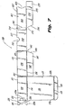
Fig. 7 is a plan view of a blank used to make the drawer portion of the dispensing box shown inFig. 3 . -
Fig. 8 is a perspective view showing the folding and assembly of the blank ofFig. 7 to form the drawer. -
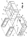
Fig. 9 is an exploded perspective view illustrating the assembly of the drawer and outer casing and the loading of suture packages in the universal dispenser box shown inFig. 3 . -
Fig. 10 illustrates the removal of the retainer tab from the universal dispenser box ofFig. 3 . -
Fig. 11 illustrates dispensing of a suture package. -
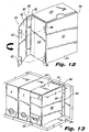
Fig. 12 is a perspective view illustrating of an alternative preferred embodiment including a spacer flap. -
Fig. 13 is a perspective view illustrating the embodiment ofFig. 12 stacked with conventional suture dispenser boxes. -
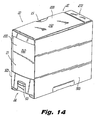
Fig. 14 is a perspective view of an alternative embodiment of the universal suture package dispenser box having a spacer extension wherein the suture packages are stacked vertically. -
Fig. 15 is a perspective view of the embodiment ofFig. 14 wherein the suture packages are stacked horizontally. -
Fig. 16 is a plan view of the blank used to make the outer casing of the embodiment ofFig. 14 . -
Fig. 17 is a perspective view illustrating the folding and assembly of the blank ofFig. 16 . -
Fig. 18 is a cutaway view of the embodiment ofFig. 14 . -
Fig. 19 is a perspective view showing the embodiment ofFig. 14 stacked with conventional suture package dispenser boxes. - With reference to
Figs. 3-11 , a preferreduniversal suture dispenser 10 is described herein.Universal suture dispenser 10 includes anouter casing 100 having a folded blank defining an interior space, and adrawer portion 200 slidably disposed within the interior space of the outer casing. Individual suture packages are preferably stacked in a single array within the drawer portion. The suture packages are typically of a rectangular, planar configuration and are stacked such that the planes are parallel to each other. The stack can be positioned vertically, as inFig. 3 , or horizontally, as inFig. 4 . The suture dispenser can be fabricated from paperboard, cardboard stock, plastic sheet material or other material suitable for the purposes described herein. - Referring now to
Fig. 3 ,universal suture dispenser 10 is illustrated in a vertical position as favored in the United States.Fig. 4 illustrates theuniversal suture dispenser 10 positioned in the European preferred horizontal orientation. - Referring now to
Fig. 5 , the blank from which theouter casing 100 is made is shown unfolded. The blank has five main panels which correspond to sides of the outer casing. Each of the panels is a flat sheet of suitable material. -
Panel 110 has a body portion 111 to whichflap 112 is attached alongfold line 118.Tab 113 is adapted for insertion into slot 155 (discussed below) and is attached tobendable portion 119 alongfold line 114.Bendable portion 119 is at least partially defined byslots fold line 115. Slots 117a and 117b betweentab 113 andbendable portion 119 facilitate the bending oftab 113 relative to thebendable portion 119 and help to prevent inadvertent withdrawal oftab 113 fromslot 155 after they have been fully engaged. -
Panel 120 has afirst strip portion 121 extending betweenpanels fold lines 122a and 122b, respectively. Asecond strip portion 124 extends betweenpanels fold lines 125a and 125b. Edges 111a of thepanel panel strip strip 121 define awindow 123.Window 123 enables the operating room personnel or other user to see identifying indicia printed on the outer side ofpanel 260 of the drawer portion 200 (Fig. 7 ) when the dispenser is assembled. -
Bendable tabs 126 are attached to stripportion 124 alongfold lines 129 and are at least partially defined byslits 128a and 128b.Finger slot 127 provides access to grasp the suture package with one's fingers (usually forefinger and thumb). -
Panel 130 includes abody portion 131 attached to first andsecond strip portions panel 140 alongfold line 132. -
Panel 150 includes abody portion 151 attached topanel 130 alongfold line 156 and also includes awindow 157 for permitting the operating room personnel or other user to read identifying indicia on the outer surface ofpanel 220 of thedrawer portion 200. -
Panel 150 also preferably includes an arcuate cut outportion 152 to facilitate grasping of the suture package for withdrawal.Tab 153 is bendably attached tobody portion 151 alongfold line 154.Slot 155 is disposed alongfold line 154 and is adapted to receivetab 113 of the first panel when the panels are folded together to form the outer casing. - Referring now to
Fig. 6 , this folding operation is illustrated.Panels fold lines Tab 112 includes a gummed adhesive surface 112a adapted to abut an inner surface portion ofpanel 140 and to adhere thereto.Panel 150 is folded withtab 153 tucked insidepanel 110 withtab 113 being inserted throughslot 155 to lock the panels and secure the enclosure. The outer casing thus formed is prepared to receive thedrawer portion 200. -
Drawer portion 200 is adapted to provide a storage space in which the suture packages are stacked. Referring toFig. 7 , as seen in unfolded plan view, the blank from which the draw portion is folded includes several foldably connected panels. -
Panel 210 includes abody portion 211.Flap 215 is attached tobody portion 211 alongfold line 213.Slits 212a and 212b facilitate folding oftab 215 and its retention in the tucked-in configuration bypanels Panel 210 is foldably attached topanel 220 alongfold line 214. -
Panel 220 includesbody portion 221 connected along one edge topanel 210 alongfold line 214 and along an adjacent edge topanel 230 alongfold line 225.Removable tab 223 is detachably connected tobody portion 221 alongarcuate score line 222.Tab 223 hasportions 223a and 223b, which are foldably connected to each other alongfold line 224.Portion 223a is at least partially defined by thearcuate score line 222 and foldline 224. Portion 223b includes an arcuate cut awayportion 225.Tab 223 is adapted to be detached frombody portion 221 by ripping along thescore line 222. -
Panel 230 includes abody portion 231 which is attached tobody portion 221 alongfold line 225, and on an opposite edge tobody portion 251 ofpanel 250 alongfold line 233, and on an adjacent edge tobody portion 241 ofpanel 240 alongfold line 232. -
Body portion 241 includes anangled side 243 with a laterally offsetportion 242 which engages slit 212b when thedrawer portion 220 is foldably assembled. The inner surface ofportion 242 provides an abutment which preventstab 215 from inadvertently being withdrawn from a folded engagement configuration. -
Panel 250 includes abody portion 251 foldably connected tobody portion 231 alongfold line 233 and totab 254 by adhesion, or other suitable means of fixation.Body portion 251 includes anarcuate cutaway portion 252 to provide access to the user's finger to grasp and pull thedrawer 200.Panel 250 forms an end panel which constitutesside 12 of the dispenser (SeeFigs. 3, 4 ). -
Panel 260 includes abody portion 261 which is foldably connected tobody portion 271 ofpanel 270 alongfold line 273.Body portion 261 includes acutaway portion 263 to facilitate grasping of the suture package by the user's finger.Tab 254 ofpanel 250 is foldably connected tobody portion 261 alongfold line 262. Foldline 262 is on the edge ofpanel 250 opposite to that offold line 233.Body portion 261 included anelongated recess 265 along an edge. -
Panel 270 includesbody portion 271 attached tobody portion 261 alongfold line 273, which is adjacent to foldline 262.Body portion 271 also includes anangled edge 274 with a laterally offsetportion 272 which engages slit 212a when thedrawer portion 220 is foldably assembled. The inner surface ofportion 272 provides an abutment which preventstab 215 from inadvertently being withdrawn from a folded engagement configuration, and acts cooperatively with corresponding lateral offsetportion 242 ofpanel 240. - Referring to
Fig. 8 , the folding assembly of thedrawer portion 200 is illustrated.Panels fold lines drawer portion 200. -
Panels fold lines Panel 210, which forms the floor of thedrawer portion 200, is then folded up withtab 215 being inserted in the space betweenbody portion 251 and anglededges panels portions slots 212b and 212a, respectively, thereby retaining thetab 215. - As can be seen from
Figs. 3, 4 ,9 and11 ,suture package dispenser 10 is a container for holding a plurality ofsuture packages 50 in a stacked array, the suture packages 50 being of generally planar, rectangular configuration, stacked parallel to each other. The suture package dispenser is characterized by a generally planarfirst side wall 11 and a generally planarsecond side wall 12,side walls side wall 13 which constitutes a top panel when the suture dispenser is positioned horizontally on a support surface, as shown inFig. 4 . Thefirst side wall 11 is defined bypanel 120 of the outer casing (Fig. 5 ) in conjunction withpanel 260 of the drawer portion (Figs. 7 ,8 ).Side wall 12 is defined bypanel 250 of the drawer portion (Figs. 7 ,8 ).Side wall 13 is defined by panel 110 (Figs. 5 ,6 ), and is substantially perpendicular toside walls third side walls second side wall 12. -
Suture package dispenser 10 includes two access portals through which the suture packages can be individually withdrawn. Afirst portal 14 is located at the bottom of thefirst side wall 11 when thesuture package dispenser 10 is positioned vertically as shown inFig. 3 . - Referring to
Figs. 3 ,9 ,10 and 11 ,removable tab 223 is initially folded over to at least partially close thefirst portal 14. To withdraw a suture package from thefirst portal 14 the user detaches tab 223 (Fig. 10 ), thereby allowing retrieval of asuture package 50. - As can be seen in
Fig. 11 , the suture packages 50 are individually withdrawn through thefirst portal 14 in a line of direction perpendicular to thefirst side wall 11 and parallel to both thesecond side wall 12 and thethird side wall 13, as in the U.S. preferred mode of dispensing. - A
second portal 15 is defined byside walls drawer portion 200 is fully inserted into theouter casing 100, thesecond portal 15 is in a closed configuration. When thedrawer portion 200 is at least partially withdrawn from theouter casing 100 thesecond portal 15 is open and asuture package 50 can be removed as in the European preferred mode. See e.g.,Fig. 2 which illustrates the European preferred mode of dispensing. - As can be seen, the suture package is removed from the second portal in a line of direction perpendicular to
third wall 13, but parallel to both thefirst side wall 11 and thesecond side wall 12, although, as mentioned above, the planes of the suture packages are perpendicular to thefirst side wall 11 and parallel to thesecond side wall 12. - Referring to
Figs. 12 and 13 , anotherembodiment 10a of the universal suture dispenser is shown. InFig. 13 , conventional suturepackage dispenser boxes 2 are shown oriented vertically for use in the U.S. preferred mode of dispensing. A typical U.S. dispenser box has a depth A, about 13.7 cm (5.4 inches). Because the width of the European style box is typically about 11.9 cm (4.7 inches) (i.e., the length ofpanel 250 betweenfold lines Fig. 7 ), universalsuture package dispenser 10 has a depth B of about 11.9 cm (4.7 inches) as well. Therefore, when both conventionalsuture package dispensers 2 and universal suture package dispensers, such as described herein, are shelved together on a U.S. rack 5 there is an uneven presentation because theuniversal suture dispenser 10 is about 1.8 cm (0.7 inches) shorter in this dimension. To make up the difference aspacer flap 180 can optionally be included as part of theouter casing 100.Spacer flap 180 preferably includes amain panel portion 181, aspacer panel 182, andinsertion tabs 183. Thespacer panel 182 is about 1.8 cm (0.7 inches) wide and makes up for the difference in depth between theuniversal suture dispenser 10 and conventionalsuture dispenser boxes 2, as shown inFig. 13 . The spacer panel also causes the dispenser box to properly fit within the U.S. style rack (i.e., the front panel of the box is flush with the front-most portion of the shelving).Spacer panel 182 is preferably fixedly attached topanel 140 of the outer casing. Themain panel portion 181 is foldably connected tospacer panel 182 alongfold line 185.Tabs 183 extend from themain panel portion 181 and are insertable intoslots 184 in theouter casing 100. - For purposes of shipping and for European style dispensing, the
spacer flap 180 can be folded back alongfold line 186 so that it is flush againstpanel 110 of theouter casing 100. The user then has the option to bend the spacer flap around to its operating position and inserttabs 183 intoslots 184 as shown inFig. 12 , thereby preparing the universalsuture package dispenser 10a for shelving withdispenser boxes 2, the U.S. preferred mode. - Referring now to
Fig. 14 , yet anotherembodiment 20 of the universal suture package dispenser is illustrated in a vertical position as favored in the United States.Fig. 15 illustratesembodiment 20 of the universal suture dispenser positioned in the European preferred horizontal orientation. Whenuniversal suture dispenser 20 is used in European style shelving or racks, theouter casing 300 is preferably discarded anddrawer 200 is placed in the rack. -
Universal dispenser box 20 is provided with a spacer to make up for the difference in dimension between the U.S. and European boxes. Unlike the embodiment shown inFigs. 12 and 13 , the spacer ofdispenser box 20 provides a back panel adapted to be completely flush against the rear wall of the U.S. rack on which they are displayed or stored. Theuniversal dispenser box 20 can employ thesame drawer portion 200 as that ofdispenser box 10. However, theouter casing 300 differs fromouter casing 100 by providing a more rigid, permanent spacing member that is oriented inward from the outer periphery of the box rather than outward of the box. More specifically, theouter casing 100 of the embodiment shown inFigs. 12 and 13 is adapted to fit thedrawer portion 200, withadditional spacer 180 being provided to adapt thedispenser box 10 to the U.S. rack 5 (Fig. 19 ).Spacer 180 is exterior to the enclosed space formed by theouter casing 100.Outer casing 300, however, is dimensioned to fit thedispenser box 20 to the rack 5 (Fig. 19 ), with the spacer portions being provided to adapt theouter casing 300 to thedrawer portion 200. The spacer panels are inside an enclosed space defined by theouter casing 300. - Referring now to
Fig. 16 , the blank from which theouter casing 300 is made is shown unfolded. The blank has five main panels which correspond to exterior sides of the outer casing, and spacer panels to adapt the interior dimensions of the enclosed space to fit thedrawer portion 200. Each of the panels is a flat sheet of suitable material. -
Panel 310 has abody portion 311 andtab 313.Tab 313 is adapted for insertion into slot 355 (discussed below) and is attached tobendable portion 319 alongfold line 314.Bendable portion 319 is at least partially defined byslots 316a and 316b, and is attached tobody portion 311 alongfold line 315.Slots 317a and 317b betweentab 313 andbendable portion 319 facilitate the bending oftab 313 relative to thebendable portion 319 and help to prevent inadvertent withdrawal oftab 313 fromslot 355 after they have been fully engaged. -
Panel 320 includes afirst strip portion 321 extending betweenpanels fold lines 322a and 322b, respectively. Asecond strip portion 324 extends betweenpanels Edges 311a of thepanel panel strip strip 321 define awindow 323.Window 323 enables the operating room personnel or other user to see identifying indicia printed on the outer side ofpanel 260 of thedrawer portion 200 when the dispenser is assembled.Finger slot 327 provides access to grasp the suture package with one's fingers (usually forefinger and thumb). -
Panel 330 includes abody portion 331 attached to first andsecond strip portions panel 340 alongfold line 332. -
Panel 340 includes abody portion 341 to whichflap 342 is attached along fold line 343. -
Panel 350 includes abody portion 351 attached topanel 330 alongfold line 356 and also includes awindow 357 for permitting the operating room personnel or other user to read identifying indicia on the outer surface ofpanel 220 of thedrawer portion 200. -
Panel 350 also preferably includes an arcuate cut outportion 352 to facilitate grasping of the suture package for withdrawal.Tab 353 is bendably attached tobody portion 351 alongfold line 354.Slot 355 is disposed alongfold line 354 and is adapted to receivetab 313 of the first panel when the panels are folded together to form the outer casing. -
Spacer panel 360 includes abody portion 361 and aspacer portion 362 which is attached tobody portion 361 alongfold line 363. Foldline 363 can include aslit 363a extending partially across the fold line.Spacer portion 362 is attached to one edge ofbody portion 341 alongfold line 364. -
Spacer panel 370 includes abody portion 371 and aspacer portion 372 which is attached tobody portion 371 alongfold line 373.Spacer portion 372 is attached to an edge of thebody portion 341 alongfold line 374. Foldline 374 can include aslit 374a extending partially across the fold line. - Referring now to
Fig. 17 , the folding operation is illustrated.Panels fold lines Tab 342 includes a gummedadhesive surface 342a adapted to abut an inner surface portion ofpanel 310 and to adhere thereto.Panel 350 is folded withtab 353 tucked insidepanel 310 withtab 313 being inserted throughslot 355 to lock the panels and secure the enclosure. Thespacer panels fold lines body portions 361 and 371) parallel to and spaced apart frombody portion 341 by a distance equal to the width ofspacer portions Body portion 361 can have a gummedsurface portion 361a to adhere tobody portion 371. The outer casing thus formed is prepared to receive thedrawer portion 200. - Referring now to
Figs. 18 and 19 , it can be seen that theouter casing 300 is adapted to correspond in dimensions to U.S. prior artsuture package dispensers 2 so that suturepackage dispenser box 20 can be shelved alone or side by side with theconventional boxes 2 on a standardized U.S. display or storage rack 5 to present a uniform array of dispenser boxes flush with the front of the shelving. Both the prior artsuture package dispensers 2 and theouter casing 300 of thesuture dispenser 20 are characterized by a depth dimension A. However, thedrawer portion 200 is characterized by a dimension L which is less than A. It is this dimension, L, that corresponds to the preferred European width for a suture dispensing box.Spacer panels body portions exterior panel 341 by a distance D equal to the width ofspacer portions drawer portion 200 are accommodated within theouter casing 300, as previously explained. Most preferably, with respect toFig. 19 , dimension A is about 13.7 cm (5.4 inches), spacer width D is about 1.8 cm (0.7 inches), height H is about 14.2 cm (5.6 inches) and box width W is about 6.4 cm (2.5 inches). Therefore, the exterior dimensions of the U.S. preferred suture dispensing box, give or take (about 13mm/0.5 inches) in each dimension, is about 6.3 x 14.2 x 13.7 cm (2.5 x 5.6 x 5.4 inches), while the European suture package dispenser drawer is about 6.3 x 14.2 x 11.9 cm (2.5 x 5.6 x 4.7 inches). - In like manner as with
suture package dispenser 10, and as can be seen fromFigs. 14 ,15 , and19 , thesuture package dispenser 20 includes a container for holding a plurality ofsuture packages 50 in a stacked array, the suture packages 50 being of generally planar configuration, stacked parallel to each other. Thesuture package dispenser 20 is characterized by a generally planarfirst side wall 21 and a generally planarsecond side wall 22,side walls side wall 23 which constitutes a top panel when the suture dispenser is positioned horizontally on a support surface, as shown inFig. 15 . Thefirst side wall 21 is defined bypanel 320 of the outer casing (Fig. 16 ) in conjunction withpanel 260 of the drawer portion (Figs. 7 ,8 ).Second side wall 22 is defined bypanel 250 of the drawer portion (Figs. 7 ,8 ).Side wall 23 is defined by panel 310 (Figs. 16 ,17 ), and is substantially perpendicular toside walls third side walls second side wall 22. -
Suture package dispenser 20 includes two access portals through which the suture packages 50 can be individually withdrawn. Afirst portal 24 is located at the bottom of thefirst side wall 21 when thesuture package dispenser 20 is positioned vertically (U.S. preferred mode) as shown inFig. 14 . -
Removable tab 223 is initially folded over to at least partially close thefirst portal 24. To withdraw a suture package from thefirst portal 24 the user detachestab 223, thereby allowing retrieval of asuture package 50. The suture packages 50 are withdrawn (by grasping a shorter side of the rectangular suture package) through thefirst portal 24 in a line of direction perpendicular to thefirst side wall 21 and parallel to both thesecond side wall 22 and thethird side wall 23, as in the U.S. preferred mode of dispensing. - The
second portal 25 is defined byside walls drawer portion 200 is fully inserted into theouter casing 300, thesecond portal 25 is in a closed configuration. When thedrawer portion 200 is at least partially withdrawn from theouter casing 300 thesecond portal 25 is open and asuture package 50 can be removed (by grasping a longer side of the rectangular suture package) as in the European preferred mode. As discussed above,drawer 200 can be removed from casing 300 and placed alone in a dispensing rack. by panel 310 (Figs. 16 ,17 ), and is substantially perpendicular toside walls third side walls second side wall 22. -
Suture package dispenser 20 includes two access portals through which the suture packages 50 can be individually withdrawn Afirst portal 24 is located at the bottom of thefirst side wall 21 when thesuture package dispenser 20 is positioned vertically (U.S. preferred mode) as shown inFig. 14 . -
Removable tab 223 is initially folded over to at least partially close thefirst portal 24. To withdraw a suture package from thefirst portal 24 the user detachestab 223, thereby allowing retrieval of asuture package 50. The suture packages 50 are withdrawn (by grasping a shorter side of the rectangular sutur package) through thefirst portal 24 in a line of direction perpendicular to thefirst side wall 21 and parallel to both thesecond side wall 22 and thethird side wall 23, as in the U.S. preferred mode of dispensing. - The
second portal 25 is defined byside walls drawer portion 200 is fully inserted into theouter casing 300 thesecond portal 25 is in a closed configuration. When the drawe:portion 200 is at least partially withdrawn from theouter casing 300 thesecond portal 25 is open and asuture package 50 can be removed (by grasping a longer side of the rectangular suture package) as in the European preferred mode. As discussed above,drawer 200 can be removed from casing 300 and placed alone in a dispensing rack. - As can be seen, the suture package is removed from the
second portal 25 in a line of direction which is perpendicular tothird wall 23, but parallel to both thefirst side wall 21 and thesecond side wall 22, although, as mentioned above, the planes of the suture packages are perpendicular to thefirst side wall 21 and parallel to thesecond side wall 22. - It can further be seen from
Fig. 18 that the interior wall formed bybody portions spacer panels first side wall 21. - The claims which follow identify embodiments of the invention additional to those described in detail above.
Claims (9)
- A set of blanks adapted to form a suture package dispenser comprising:a) a blank for an outer casing (100) which includes a first panel (110), a second panel (120) foldably connected to the first panel along an edge (111a) thereof, a third panel (130) foldably connected to the second panel along an edge (131a) of the second panel opposite to the edge at which the first panel is foldably connected, a fourth panel (140) foldably connected to the third panel along an edge (132) of the third panel opposite to that at which the second panel is connected, and a fifth panel (150) foldably connected to the third panel along an edge (156); said first, second, third, fourth and fifth panels are adapted to be forming at least a partial enclosure defining an interior space and an opening in one side corresponding to a first access portal (14) and an open end corresponding to a second access portal (15) through which first and second access portals a suture package can be individually withdrawn;b) a blank for a drawer portion (200) adapted to be slidably disposed within the interior space of the outer casing (100) and at least partially withdrawable through the second access portal in the open end of the outer casing, such that when the drawer portion (200) is at least partially withdrawn from the outer casing (100) the second access portal (15) is open and a suture package (50) can be removed from the second access portal (15), the drawer portion blank including first (210), second (220), third (230), fourth (240), fifth (250), sixth (260), and seventh (270) panels, the first and third panels being foldably connected to the second panel along respective adjacent edges (214, 215) of the second panel, the fifth and fourth panels being foldably connected to the third panel along respective adjacent edges (232, 233) of the third panel, and the fifth and seventh panels being foldably connected to the sixth panel along respective adjacent edges (272, 273) of the sixth panel, the first, second, third, fourth, fifth, sixth, and seventh panels being adapted to be folded to form a storage space for suture packages, wherein the second panel of the drawer portion includes a tab (223) removably attached to the second panel along an arcuate score line (222), so that when detached by a user, a suture package (50) can be withdrawn from the first access portal (14).
- The set of blanks of claim 1 wherein the second panel and the fifth panel of the outer casing each have a window (123, 157).
- The set of blanks of claim 1 or 2 wherein the first panel includes a tab (113) and the fifth panel includes a slot (155) into which the tab is inserted.
- The set of blanks of any one of claims 1 to 3 wherein the fifth panel and second panel of the drawer portion are foldably attached to opposite edges (233, 225) of the third panel.
- The set of blanks of any one of claims 1 to 4 wherein the sixth panel and third panel of the drawer portion are foldably attached to opposite edges (233, 262) of the fifth panel.
- The set of blanks of any one of claims 1 to 5 wherein said outer casing and drawer portion are fabricated from paperboard and/or plastic sheet.
- The set of blanks of any one of claims 1 to 6 formed into a suture package dispenser.
- The suture package dispenser of claim 7, further including a plurality of substantially planar suture packages (50) stacked in an array such that the suture packages are parallel to each other and parallel to second and fifth panels of the drawer portion.
- The suture package dispenser of claim 7 or 8, wherein the first access portal (14) permits the suture packages to be withdrawn from the dispenser in a linear direction perpendicular to the second panel of the outer casing, and the second access portal (15) permits withdrawal of the suture packages in a line of direction perpendicular to the first panel of the outer casing.
Applications Claiming Priority (3)
| Application Number | Priority Date | Filing Date | Title |
|---|---|---|---|
| US08/680,947 US5860517A (en) | 1996-07-16 | 1996-07-16 | Universal suture dispenser box |
| US680947 | 1996-07-16 | ||
| EP97111642A EP0819408B1 (en) | 1996-07-16 | 1997-07-09 | Universal dispenser box for suture packages |
Related Parent Applications (1)
| Application Number | Title | Priority Date | Filing Date |
|---|---|---|---|
| EP97111642A Division EP0819408B1 (en) | 1996-07-16 | 1997-07-09 | Universal dispenser box for suture packages |
Publications (2)
| Publication Number | Publication Date |
|---|---|
| EP1295562A1 EP1295562A1 (en) | 2003-03-26 |
| EP1295562B1 true EP1295562B1 (en) | 2008-12-31 |
Family
ID=24733167
Family Applications (2)
| Application Number | Title | Priority Date | Filing Date |
|---|---|---|---|
| EP02028066A Expired - Lifetime EP1295562B1 (en) | 1996-07-16 | 1997-07-09 | Universal suture dispenser box |
| EP97111642A Expired - Lifetime EP0819408B1 (en) | 1996-07-16 | 1997-07-09 | Universal dispenser box for suture packages |
Family Applications After (1)
| Application Number | Title | Priority Date | Filing Date |
|---|---|---|---|
| EP97111642A Expired - Lifetime EP0819408B1 (en) | 1996-07-16 | 1997-07-09 | Universal dispenser box for suture packages |
Country Status (5)
| Country | Link |
|---|---|
| US (2) | US5860517A (en) |
| EP (2) | EP1295562B1 (en) |
| CA (1) | CA2207984C (en) |
| DE (2) | DE69725229T2 (en) |
| ES (2) | ES2317976T3 (en) |
Families Citing this family (26)
| Publication number | Priority date | Publication date | Assignee | Title |
|---|---|---|---|---|
| WO1999018860A1 (en) * | 1997-10-15 | 1999-04-22 | Tyco Group S.A.R.L. | Universal storage box for dispensing a medical device |
| US6042151A (en) * | 1998-08-11 | 2000-03-28 | Ali; Terry | Single sheet sandpaper delivery system with single sheet sandpaper having application coordinating indicia and legend |
| US6610071B1 (en) * | 1999-07-26 | 2003-08-26 | Beth Israel Deaconess Medical Center | Suture system |
| US6237757B1 (en) * | 1999-09-21 | 2001-05-29 | Ethicon, Inc. | Horizontal drop-feed, dispenser box |
| PT1120360E (en) * | 2000-01-25 | 2004-01-30 | Georgia Pacific France | BOX FOR THE DISTRIBUTION THAT PRESENTS TWO OPPOSITES OPPOSED BETWEEN |
| AR024489A1 (en) | 2000-06-26 | 2002-10-02 | Cinese Antonio Enrique | TRANSPORTABLE TABLE FOR FAST IDENTIFICATION OF SURGICAL SUTURES AND ACCESSORIES |
| US6409016B1 (en) | 2000-06-27 | 2002-06-25 | Genzyme Corporation | Holder and dispenser for spools, tube-shaped devices, and cylindrical devices with recessed ends |
| FR2823965B1 (en) * | 2001-04-30 | 2003-10-31 | Georgia Pacific France | PAPER ITEM DISTRIBUTOR |
| US6598737B2 (en) | 2001-07-05 | 2003-07-29 | Ethicon, Inc. | Angled dispenser box for sutures |
| GB2380927A (en) * | 2001-08-06 | 2003-04-23 | Duncan James Hill | Joinable rack type holders for sutures and ligatures |
| US20040094568A1 (en) * | 2002-11-15 | 2004-05-20 | Dailey Robert W. | Packaging systems for display and distribution of products |
| US6860400B2 (en) * | 2003-03-18 | 2005-03-01 | Caraustar Custom Packaging | Container with friction dispenser |
| US7467710B2 (en) | 2005-05-04 | 2008-12-23 | Ethicon, Inc. | Molded package |
| US7717838B2 (en) * | 2005-12-16 | 2010-05-18 | Smurfit-Stone Container Enterprises, Inc. | Blank and methods and apparatus for forming a dispenser case from the blank |
| US7475777B2 (en) * | 2006-05-31 | 2009-01-13 | Graphic Packaging International, Inc. | Carton with article retaining feature |
| USD587997S1 (en) * | 2008-03-04 | 2009-03-10 | Cwip Nominee Trust | Container for dispensing garments |
| RU2376222C2 (en) * | 2008-04-17 | 2009-12-20 | Иван Владимирович Коробицин | Packing box and packing units for it |
| US20120305584A1 (en) | 2011-06-06 | 2012-12-06 | Omnicare Inc. | Administration methods and packagings for oral medications |
| USD670178S1 (en) | 2011-06-06 | 2012-11-06 | Omnicare, Inc. | Medication packaging assembly |
| USD683243S1 (en) | 2011-07-14 | 2013-05-28 | Omnicare Inc. | Medication packaging |
| WO2013059237A1 (en) * | 2011-10-17 | 2013-04-25 | Ice House America, Llc | Collapsible containers, collapsible container dispensers, and methods of dispensing a collapsible container |
| US10207858B2 (en) * | 2013-08-28 | 2019-02-19 | Stephanie Tan | Combination food pad container and dispenser |
| US9994344B2 (en) | 2014-01-21 | 2018-06-12 | Westrock Shared Services, Llc | Shipping container convertible into a dispenser container or a display tray |
| CN114126984B (en) * | 2019-06-19 | 2023-08-29 | 希悦尔公司 | System and container for dispensing packages of items of mail |
| USD916365S1 (en) | 2019-09-03 | 2021-04-13 | Republic Tobacco L.P. | Dispensing box holder |
| US11064734B2 (en) * | 2019-10-01 | 2021-07-20 | Republic Tobacco L.P. | Dispensing box holder |
Family Cites Families (35)
| Publication number | Priority date | Publication date | Assignee | Title |
|---|---|---|---|---|
| US902347A (en) * | 1903-01-17 | 1908-10-27 | Benjamin C Tillinghast | Vending carton or package. |
| US1119213A (en) * | 1913-12-29 | 1914-12-01 | Alfred Abt | Single-delivery paper box. |
| US1823572A (en) * | 1930-02-26 | 1931-09-15 | William P Reed | Dispensing container |
| US1973237A (en) * | 1932-05-25 | 1934-09-11 | William H Vilas | Carton |
| US2005924A (en) * | 1932-12-15 | 1935-06-25 | Sutherland Paper Co | Dispensing carton |
| US1986101A (en) * | 1933-01-21 | 1935-01-01 | Johnson & Johnson | Box |
| US2002485A (en) * | 1934-11-26 | 1935-05-28 | American Sugar Refining Co | Carton |
| US2577862A (en) * | 1948-04-01 | 1951-12-11 | Shaw Randall Company Inc | Dispensing container for stacked elongated articles |
| US2755922A (en) * | 1954-11-24 | 1956-07-24 | Iverslee Company | Sealed dispensing package |
| NL209785A (en) * | 1955-10-03 | |||
| US2785843A (en) * | 1956-06-26 | 1957-03-19 | Philip Morris Inc | Display and dispensing device for a stack of packages |
| US3014634A (en) * | 1958-05-12 | 1961-12-26 | Design Dynamics Inc | Dispensing container |
| US3156378A (en) * | 1962-08-20 | 1964-11-10 | William J Bua | Article dispenser having a removable supply cartridge |
| US3160342A (en) * | 1963-02-20 | 1964-12-08 | Thomas G Murdock | Article dispensing container |
| US3356279A (en) * | 1966-02-23 | 1967-12-05 | Reynolds Metals Co | Shipping and dispensing container means and blanks therefor |
| US3450308A (en) * | 1967-10-06 | 1969-06-17 | William C Schoenefeld | Article dispenser having an inclined bottom ramp and a front wall article outlet opening |
| US3568883A (en) * | 1969-03-21 | 1971-03-09 | Voys Inc Le | Carton dispenser for wrapped articles |
| US3586206A (en) * | 1969-04-29 | 1971-06-22 | Bess P Gilmore | Container for a stack of articles |
| US3580472A (en) * | 1969-06-10 | 1971-05-25 | Becton Dickinson Co | Swab dispenser for package therefor |
| US4148413A (en) * | 1977-04-13 | 1979-04-10 | Display Originals, Inc. | Multi-channelbox-dispenser unit |
| US4170325A (en) * | 1978-06-20 | 1979-10-09 | American Can Company | Receptacle |
| USD260955S (en) | 1978-07-19 | 1981-09-29 | Ethicon, Inc. | Modular suture cabinet box |
| US4186866A (en) * | 1979-01-25 | 1980-02-05 | Container Corporation Of America | Dispenser container with cover |
| US4215777A (en) * | 1979-04-09 | 1980-08-05 | Strickland Ola D | Suture holding case |
| FR2458480A1 (en) * | 1979-06-13 | 1981-01-02 | Fabre Sa Pierre | Folded sheet sachet dispenser - is made from single sheet of cardboard and has tear=off tongue in base to allow access to sachets |
| IT8022095V0 (en) * | 1980-06-23 | 1980-06-23 | Meschi Ind Grafica | CONTAINER FOR SHEETS. |
| US4396143A (en) * | 1981-08-31 | 1983-08-02 | Manville Service Corporation | Multiple article beverage package |
| US4405044A (en) * | 1981-09-17 | 1983-09-20 | Ethicon, Inc. | Dispenser box for packages of sterile sutures |
| US4497432A (en) * | 1983-10-07 | 1985-02-05 | Carlisle Laboratories, Inc. | Dispenser package assembly |
| US4566607A (en) * | 1984-05-24 | 1986-01-28 | Smith David L | Bag dispenser |
| US5282533A (en) * | 1990-12-17 | 1994-02-01 | United States Surgical Corporation | Suture display rack and procedure kit |
| US5249737A (en) * | 1991-09-09 | 1993-10-05 | Ecolab Inc. | Method for dispensing moisture-sensitive unit dose packages |
| US5284293A (en) * | 1993-01-21 | 1994-02-08 | Ethicon, Inc. | Dispenser box for packages of sterile sutures |
| US5458272A (en) * | 1994-06-27 | 1995-10-17 | Packaging Corporation Of America | Paperboard dispenser having separately formed drawer |
| US5542539A (en) * | 1995-04-04 | 1996-08-06 | Ethicon Endo-Surgery, Inc. | Container for quick release packages for surgical instruments |
-
1996
- 1996-07-16 US US08/680,947 patent/US5860517A/en not_active Expired - Lifetime
-
1997
- 1997-05-12 US US08/854,823 patent/US5988367A/en not_active Expired - Lifetime
- 1997-06-16 CA CA002207984A patent/CA2207984C/en not_active Expired - Fee Related
- 1997-07-09 DE DE69725229T patent/DE69725229T2/en not_active Expired - Lifetime
- 1997-07-09 EP EP02028066A patent/EP1295562B1/en not_active Expired - Lifetime
- 1997-07-09 EP EP97111642A patent/EP0819408B1/en not_active Expired - Lifetime
- 1997-07-09 ES ES02028066T patent/ES2317976T3/en not_active Expired - Lifetime
- 1997-07-09 DE DE69739196T patent/DE69739196D1/en not_active Expired - Lifetime
- 1997-07-09 ES ES97111642T patent/ES2203739T3/en not_active Expired - Lifetime
Also Published As
| Publication number | Publication date |
|---|---|
| EP0819408A2 (en) | 1998-01-21 |
| US5860517A (en) | 1999-01-19 |
| DE69725229D1 (en) | 2003-11-06 |
| EP0819408A3 (en) | 1998-03-11 |
| CA2207984A1 (en) | 1998-01-16 |
| DE69725229T2 (en) | 2004-08-19 |
| ES2317976T3 (en) | 2009-05-01 |
| DE69739196D1 (en) | 2009-02-12 |
| US5988367A (en) | 1999-11-23 |
| EP0819408B1 (en) | 2003-10-01 |
| EP1295562A1 (en) | 2003-03-26 |
| ES2203739T3 (en) | 2004-04-16 |
| CA2207984C (en) | 2006-04-11 |
Similar Documents
| Publication | Publication Date | Title |
|---|---|---|
| EP0819408B1 (en) | Universal dispenser box for suture packages | |
| US5813597A (en) | Dual orientation dispenser carton | |
| EP2213251B1 (en) | Molded package | |
| US4444314A (en) | Storing device for flat objects | |
| US5358113A (en) | Dispenser for tape rolls | |
| US4206869A (en) | Shelf storage box | |
| US4438846A (en) | Cassette box construction | |
| US20050000975A1 (en) | Sterile surgical glove dispenser | |
| US4978009A (en) | Video cassette box with removable panel | |
| EP0373746A1 (en) | Display and dispensing carton | |
| US6598737B2 (en) | Angled dispenser box for sutures | |
| US5332117A (en) | Adjustable tissue box | |
| US5836451A (en) | Carton having tray and return carton | |
| US6216944B1 (en) | Collapsible gravity feed display | |
| US7043888B2 (en) | Wound film dispenser with exterior retainer and method for manufacturing same | |
| US5308360A (en) | Key storage container | |
| CA2533634C (en) | Universal suture dispenser box | |
| US7331475B2 (en) | Organizer | |
| JP2001180655A (en) | Packaging container | |
| JPH0414348Y2 (en) | ||
| CA2250793C (en) | A package assembly for keeping, storing, displaying and handling disc-shaped products | |
| WO1993022955A1 (en) | A product display unit and dispenser |
Legal Events
| Date | Code | Title | Description |
|---|---|---|---|
| PUAI | Public reference made under article 153(3) epc to a published international application that has entered the european phase |
Free format text: ORIGINAL CODE: 0009012 |
|
| AC | Divisional application: reference to earlier application |
Ref document number: 0819408 Country of ref document: EP Kind code of ref document: P |
|
| AK | Designated contracting states |
Kind code of ref document: A1 Designated state(s): DE ES FR GB IT |
|
| 17P | Request for examination filed |
Effective date: 20030522 |
|
| AKX | Designation fees paid |
Designated state(s): DE ES FR GB IT |
|
| GRAP | Despatch of communication of intention to grant a patent |
Free format text: ORIGINAL CODE: EPIDOSNIGR1 |
|
| GRAS | Grant fee paid |
Free format text: ORIGINAL CODE: EPIDOSNIGR3 |
|
| GRAA | (expected) grant |
Free format text: ORIGINAL CODE: 0009210 |
|
| AC | Divisional application: reference to earlier application |
Ref document number: 0819408 Country of ref document: EP Kind code of ref document: P |
|
| AK | Designated contracting states |
Kind code of ref document: B1 Designated state(s): DE ES FR GB IT |
|
| REG | Reference to a national code |
Ref country code: GB Ref legal event code: FG4D |
|
| REF | Corresponds to: |
Ref document number: 69739196 Country of ref document: DE Date of ref document: 20090212 Kind code of ref document: P |
|
| REG | Reference to a national code |
Ref country code: ES Ref legal event code: FG2A Ref document number: 2317976 Country of ref document: ES Kind code of ref document: T3 |
|
| PLBE | No opposition filed within time limit |
Free format text: ORIGINAL CODE: 0009261 |
|
| STAA | Information on the status of an ep patent application or granted ep patent |
Free format text: STATUS: NO OPPOSITION FILED WITHIN TIME LIMIT |
|
| 26N | No opposition filed |
Effective date: 20091001 |
|
| PGFP | Annual fee paid to national office [announced via postgrant information from national office to epo] |
Ref country code: ES Payment date: 20110726 Year of fee payment: 15 |
|
| PGFP | Annual fee paid to national office [announced via postgrant information from national office to epo] |
Ref country code: IT Payment date: 20110727 Year of fee payment: 15 |
|
| PG25 | Lapsed in a contracting state [announced via postgrant information from national office to epo] |
Ref country code: IT Free format text: LAPSE BECAUSE OF NON-PAYMENT OF DUE FEES Effective date: 20120709 |
|
| REG | Reference to a national code |
Ref country code: ES Ref legal event code: FD2A Effective date: 20131021 |
|
| PG25 | Lapsed in a contracting state [announced via postgrant information from national office to epo] |
Ref country code: ES Free format text: LAPSE BECAUSE OF NON-PAYMENT OF DUE FEES Effective date: 20120710 |
|
| REG | Reference to a national code |
Ref country code: FR Ref legal event code: PLFP Year of fee payment: 20 |
|
| PGFP | Annual fee paid to national office [announced via postgrant information from national office to epo] |
Ref country code: GB Payment date: 20160627 Year of fee payment: 20 |
|
| PGFP | Annual fee paid to national office [announced via postgrant information from national office to epo] |
Ref country code: FR Payment date: 20160622 Year of fee payment: 20 |
|
| PGFP | Annual fee paid to national office [announced via postgrant information from national office to epo] |
Ref country code: DE Payment date: 20160622 Year of fee payment: 20 |
|
| REG | Reference to a national code |
Ref country code: DE Ref legal event code: R071 Ref document number: 69739196 Country of ref document: DE |
|
| REG | Reference to a national code |
Ref country code: GB Ref legal event code: PE20 Expiry date: 20170708 |
|
| PG25 | Lapsed in a contracting state [announced via postgrant information from national office to epo] |
Ref country code: GB Free format text: LAPSE BECAUSE OF EXPIRATION OF PROTECTION Effective date: 20170708 |