EP1295005B1 - Formation d'un trou de forage au moyen d'un tubage spirale - Google Patents
Formation d'un trou de forage au moyen d'un tubage spirale Download PDFInfo
- Publication number
- EP1295005B1 EP1295005B1 EP01940834A EP01940834A EP1295005B1 EP 1295005 B1 EP1295005 B1 EP 1295005B1 EP 01940834 A EP01940834 A EP 01940834A EP 01940834 A EP01940834 A EP 01940834A EP 1295005 B1 EP1295005 B1 EP 1295005B1
- Authority
- EP
- European Patent Office
- Prior art keywords
- motor
- whipstock
- anchor
- downhole
- fluid
- Prior art date
- Legal status (The legal status is an assumption and is not a legal conclusion. Google has not performed a legal analysis and makes no representation as to the accuracy of the status listed.)
- Expired - Lifetime
Links
Images


Classifications
-
- E—FIXED CONSTRUCTIONS
- E21—EARTH DRILLING; MINING
- E21B—EARTH DRILLING, e.g. DEEP DRILLING; OBTAINING OIL, GAS, WATER, SOLUBLE OR MELTABLE MATERIALS OR A SLURRY OF MINERALS FROM WELLS
- E21B29/00—Cutting or destroying pipes, packers, plugs, or wire lines, located in boreholes or wells, e.g. cutting of damaged pipes, of windows; Deforming of pipes in boreholes or wells; Reconditioning of well casings while in the ground
- E21B29/06—Cutting windows, e.g. directional window cutters for whipstock operations
-
- E—FIXED CONSTRUCTIONS
- E21—EARTH DRILLING; MINING
- E21B—EARTH DRILLING, e.g. DEEP DRILLING; OBTAINING OIL, GAS, WATER, SOLUBLE OR MELTABLE MATERIALS OR A SLURRY OF MINERALS FROM WELLS
- E21B4/00—Drives for drilling, used in the borehole
- E21B4/02—Fluid rotary type drives
-
- E—FIXED CONSTRUCTIONS
- E21—EARTH DRILLING; MINING
- E21B—EARTH DRILLING, e.g. DEEP DRILLING; OBTAINING OIL, GAS, WATER, SOLUBLE OR MELTABLE MATERIALS OR A SLURRY OF MINERALS FROM WELLS
- E21B7/00—Special methods or apparatus for drilling
- E21B7/04—Directional drilling
- E21B7/06—Deflecting the direction of boreholes
- E21B7/061—Deflecting the direction of boreholes the tool shaft advancing relative to a guide, e.g. a curved tube or a whipstock
Definitions
- the present invention relates to oil field tools. More specifically, the invention relates to an apparatus for and a method of using a motor in a tubular member disposed in a wellbore.
- oil field wells are drilled as a vertical shaft to a subterranean producing zone forming a wellbore, the wellbore is lined with a steel tubular casing, and the casing is perforated to allow production fluid to flow into the casing and up to the surface of the well.
- oil field technology has increasingly used sidetracking or directional drilling to further exploit the resources of productive regions.
- sidetracking an exit, such as a slot or window, is cut in a steel cased wellbore typically using a mill, where drilling is continued through the exit at angles to the vertical wellbore.
- directional drilling a wellbore is cut in strata at an angle to the vertical shaft typically using a drill bit.
- the mill and the drill bit are rotary cutting tools having cutting blades or surfaces typically disposed about the tool periphery and in some models on the tool end.
- components including an anchor, a whipstock coupled to the anchor and a rotary cutting tool that progresses downward along the whipstock are used to cut the angled exit through the casing in the wellbore.
- the whipstock is an elongated cylindrical wedge-shaped member having an inclined concave deflection surface and guides the angle of the rotary cutting tool progressively outward to cut the exit.
- One or more of the components are attached to a tubing member, such as drill pipe or coiled tubing, that is used to lower the components into the wellbore.
- the anchor typically is a bridge plug, packer or another supporting or sealing member. The anchor is set in a downhole position and extends across the wellbore to form an abutting surface for placement of subsequent equipment.
- the anchor can be secured in the wellbore by mechanical or hydraulic actuation of a set of jaws directed outward toward the casing or wellbore.
- Hydraulic actuation generally requires a fluid source from the surface that pressurises a cavity in the anchor to actuate the jaws.
- a trip generally includes lowering a tubular member with a cutting tool or other component into the wellbore, performing the intended operation, and then retrieving the members to the surface.
- the first trip sets the anchor in the wellbore
- the second trip sets the whipstock to the anchor
- the third trip actuates the cutting tool to cut the exit along the whipstock.
- Angular orientation of the whipstock in the wellbore is important to properly direct the drilling or cutting. Most methods of orientation and initiation of cutting require multiple tips.
- Some systems allow orienting and setting of the whipstock in a single trip of a drill string in combination with a wireline survey instrument.
- a known system includes an anchor, a whipstock and a cutter connected to a drill string.
- a wireline survey instrument is inserted through the drill string to determine proper orientation prior to setting the whipstock.
- the flow can prematurely set the anchor, unless some device such as a selectively actuated bypass valve is used to divert the flow. Further, such methods require the separate use of the wireline survey instrument.
- MWD measuring-while-drilling
- an MWD tool in an assembly with a hydraulic anchor has challenges.
- Typical MWD tools require drilling fluid flow rates even greater than the flow rate required to push the wireline survey instrument downhole and increases the likelihood of inadvertently setting the anchor.
- an increased flow rate bypass valve can be used as described in U.S. Pat. No. 5,443,129.
- the system is suitable for a typical drill string that is rotated by a conventional drilling apparatus on a surface derrick.
- the disclosure does not address the current trends of using more flexible coiled tubing requiring a downhole motor to rotate the cutting tool without substantially rotating the coiled tubing.
- Coiled tubing is increasingly being used to lower the costs of drilling and producing a well.
- Coiled tubing is a continuous line of tubing typically wound on a reel on a mobile surface unit that can be inserted downhole without having to assemble and disassemble numerous threaded joints of a drill string.
- the coiled tubing is not sufficiently rigid to accommodate rotational torque from the surface of the well along the tubing length to rotate the cutting tool in contrast to systems using drill pipe.
- a downhole motor is mounted on the coiled tubing to rotate a cutting tool. Drilling fluid flowed through the interior of the coiled tubing is used to actuate the motor to rotate the cutting tool or other members.
- FIG. 1 is a schematic cross sectional view of a power section 1 of such a progressive cavity motor.
- FIG 1A is a schematic cross sectional view of the downhole motor shown in Figure 1. Similar elements are similarly numbered and the figures will be described in conjunction with each other.
- the power section 1 includes an outer stator 2, an inner rotor 4 disposed within the stator.
- An elastomeric member 7 is formed between the stator and rotor and is typically a part of the stator.
- the rotor 4 includes a plurality of lobes 6 formed in a helical pattern around the circumference of the rotor.
- the stator includes a plurality of receiving surfaces 8 formed in the elastomeric member for the lobes 6. The number of receiving surfaces is typically one more than the number of lobes.
- the lobes 6 are produced with matching lobe profiles and a similar helical pitch compared to the receiving surfaces in the stator.
- the rotor can be matched to and inserted within the stator. Fluid flowing from the inlet 3 through the motor creates hydraulic pressure that causes the rotor 4 to rotate within the stator 2, as well as precess around the circumference of the receiving surfaces 8.
- a progressive cavity 9 is created that progresses from the inlet 3 to the outlet 5 as the rotor is rotated within the stator 2. Fluid contained within the cavity is thereby exhausted through the outlet 5.
- the hydraulic pressure, causing the rotor to rotate provides output torque for various tools attached to the motor.
- US-A-5363929 describes a composite torque shaft for use with a progressive cavity motor.
- US-A-5186265 describes a retrievable drill-bit driven by a progressive cavity motor.
- EP-A-0685628 describes a system for drilling a lateral wellbore which includes running a position measuring tool, a whipstock and an anchor together into a wellbore on coiled tubing.
- the present invention provides a system and method for orienting setting an anchor, a whipstock, a cutting tool and a downhole motor coupled to a tubular member, such as coiled tubing.
- the motor allows flow therethrough sufficient to actuate an MWD or other position measuring tool, and an orienter if so equipped, and substantially retains the orientation of the motor with the coupled whipstock.
- An increased flow rate or pressure actuates the motor once the whipstock is set and rotation of the cutting tool or other equipment can begin.
- a method of operating a downhole tool comprising: coupling the downhole tool to a tubular member, the downhole tool comprising a position measuring tool; and characterised by: coupling a downhole motor to the tubular member; and selectively maintaining the downhole motor in a substantially unactuated condition while flowing a fluid through the downhole motor sufficient to operate the downhole tool; and operating the downhole tool.
- the invention provides an apparatus for use in a wellbore, comprising a motor body, a motor shaft disposed at least partially internal to the motor body, and a fluid channel in communication with the motor shaft, and a downhole tool disposed below the motor body, the motor shaft being substantially unactuated while fluid flows through the motor body to actuate the downhole tool, wherein the apparatus further comprises a position measuring tool.
- Figure 2 is a schematic cross sectional view of a tubing member inserted into the wellbore.
- the well is drilled through a surface 11 to establish a wellbore 10.
- the wellbore is cased with a casing 14.
- a space 12 between the drilled wellbore and the casing 14 is sealed with a solidifying aggregate such as concrete.
- a reel 13 is disposed adjacent the wellbore 10 and contains a quantity of tubing, such as coiled tubing 15.
- the coiled tubing 15 typically does not rotate to a significant degree within the wellbore.
- the reel 13 of coiled tubing provides an amount of tubing that can be relatively rapidly inserted in and removed from the wellbore 10 compared to drill pipe or tubing which must be assembled and reassembled in sections.
- An anchor 18 such as a bridge plug, packer, or other setting device, is attached to the tubing generally on a lower end of the arrangement.
- a whipstock 20 is attached to the anchor 18 and includes an elongated tapered surface that guides the cutter 22, such as an end mill, outwardly toward casing 14.
- a cutting tool 22 is attached to the whipstock with a connection member 24.
- a connection member 24 can be a piece of metal that is later sheared downhole as the cutting tool is actuated.
- a spacer mill 26 can then be coupled to the cutting tool 22. The spacer mill 26 typically is a mill used to further define the hole or exit created by the cutting tool 22.
- a stabilizer sub 28 is attached to the coiled tubing 15.
- the stabilizer sub 28 has extensions protruding from the exterior surface to assist in concentrically retaining the tubing member and components in the wellbore 10.
- a motor 30 can be attached to the arrangement of components above the cutters. The motor 30 is used to rotate the cutters while the coiled tubing remains relatively rotationally stable.
- the motor 30 allows a quantity of fluid to flow through the motor without rotation of the motor at a first time and then allows a second quantity and/or pressure of fluid to flow through the motor at a second time to rotate the cutters.
- a position measuring member 32 such as an MWD tool, is coupled above the motor 30.
- the position measuring member 32 requires a certain level of flow, typically 80-100 gallons per minute (6-8 litres per second), to actuate and provide feedback to equipment located at the surface 11.
- An orienter 34 is coupled to the coiled tubing 15 above the position measuring member 32.
- the orienter 34 is a device that enables incremental angular rotation of the components to orient the whipstock in a certain direction.
- An exemplary orienter is available from Weatherford International.
- the orienter 34 is actuated by starting circulation and stopping circulation of fluid flowing down the coiled tubing 15. Each pulse of fluid indexes the orienter, generally, about 15-30° depending upon the tool.
- the orienter 34 can rotate the arrangement containing the whipstock to a desired orientation within the wellbore, while the position measuring member 32 provides feedback to determine the orientation.
- utilising an MWD tool with a motor on a coiled tubing while orienting the whipstock has not been available.
- the flow required to actuate the orienter 34 and position measuring member 32 would typically turn the motor 30 and change the orientation of whipstock 20.
- the accuracy of the alignment between the orienter and the whipstock would be changed and become unknown downhole.
- the anchor 18 may be separately coupled to the coiled tubing 15 and set in position in one trip.
- the other components such as the whipstock, mill, motor, orienter and position measuring member may then be inserted downhole in a second trip.
- the anchor and the whipstock may be inserted in a first trip and the other components inserted in a second trip.
- the motor 30 allows flow without substantial rotation at a first flow rate and/or pressure to allow sufficient flow through the orienter 34 and the position measuring member 32 without actuation of the motor, as described with reference to Figures 8-9.
- the flow in the tubing member through the orienter, position measuring member and motor is then exhausted through ports in the end mill and flows outwardly and then upwardly through the wellbore 10 back to the surface 11.
- Flow through or around the motor 30 allows the reduction of at least one trip in setting the anchor 18 and starting to drill the exit in the wellbore 10.
- Figures 3-5 are cross sectional views of a wellbore, showing a exemplary sequence in setting a mechanical anchor, orienting the whipstock, and beginning to cut an exit in two trips.
- Various components including an anchor 18, a whipstock 20, a cutting tool 22, a motor 30, a position measuring member 32 and an orienter 34 are coupled to the tubing member 16, such as coiled tubing.
- Figure 3 is a schematic cross sectional view of an anchor inserted downhole in the wellbore.
- a tubing member 16, such as coiled tubing is inserted downhole through the wellbore 10 and inside the casing 14.
- An anchor 18, such as a mechanical anchor, is coupled to the lower end of the tubing member.
- the mechanical anchor 18 requires mechanical actuation to set the anchor in position, as known to those with ordinary skill in the art. After the anchor 18 is set, the anchor is released from the tubing member and the tubing member is retrieved back to the surface.
- Figure 4 is a schematic cross sectional view of various components coupled to the tubing member 16 after the anchor 18 is set.
- a whipstock 20 is attached to a cutting tool 22 through a connection member 24.
- a spacer mill 26 is coupled to the cutting tool 22.
- a stabilizer sub 28 is coupled to the spacer mill 26 and a motor 30 is coupled to the stabilizer sub.
- a position measuring member 32 is coupled to the motor 30 and an orienter 34 is coupled to the position measuring member.
- the orienter is also coupled to the tubing member 16.
- the term "coupled” as used herein includes at least two components directly coupled together or indirectly coupled together with intervening components coupled therebetween.
- the tubing member 16 and the components coupled thereto are lowered downhole, so that the whipstock 20 is adjacent the anchor 18. Fluid flow through the tubing member 16 is used to actuate the orienter 34 and rotationally index the components below the orienter to a desired orientation.
- the position measuring member 32 provides feedback to the equipment located generally on the surface 11 (shown in Figure 2) to determine the position of the whipstock 20 to an operator.
- the motor 30 allows sufficient flow through the orienter 34 and the position measuring member 32 to allow actuation thereof without rotating the motor 30 and the components attached therebelow. Thus, a relative alignment between the position measuring member, orienter, motor, mills, and whipstock is maintained. Once the whipstock is properly oriented, the tubing member 16 is further lowered, so that the whipstock 20 engages the anchor 18 and is set in position.
- Figure 5 is a schematic cross sectional of the whipstock 20 set in position and the cutting tool 22 cutting an exit through the casing 14 at an angle to the wellbore 10.
- the motor 30 is actuated and turns the cutting tool 22. Sufficient torque created by the motor 30 shears the connection member 24 between the whipstock 20 and the cutting tool 22.
- the cutting tool 22 begins to turn and is guided at an angle to the wellbore 10 by the whipstock 20.
- the cutting tool 22 cuts at an angle through the casing 10 and creates an angled exit therethrough.
- the casing 14 may not be placed in a wellbore 10. It is to be understood that the arrangements described herein for cutting an angled exit apply regardless of whether the casing 14 is placed in the wellbore.
- the orienter 34 is designed to be rotationally stable during the operation of the motor 30 because the pressure is not pulsed from a low to high pressure that otherwise actuates the orienter. However, if the orienter 34 is actuated and does index, the change of the orienter does not effect the ability of the motor 30 to operate the cutting tool 22 nor the direction of the end mill because the end mill is guided by the whipstock 20.
- Figure 6 is a schematic cross sectional view of an arrangement of components using a hydraulic anchor 38.
- Figure 6 shows the arrangement being inserted downhole in the wellbore and includes a hydraulic actuator 35 coupled to a corresponding set of components described in reference to Figures 2-5.
- the components include, for example, an anchor 20 and a cutting tool 22 coupled to the anchor 20 with a connection member 24.
- the arrangement includes a spacer mill 26, a stabilizer sub 28, a motor 30, a position measuring member 32 and an orienter 34 coupled to a tubing member 16.
- a hydraulic anchor 38 can be actuated remotely and thus does not require a separate trip, as described in reference to Figure 3. Therefore, the arrangement shown in Figure 6 can be used to set the anchor and the whipstock and begin cutting an exit in wellbore in a single trip.
- the arrangement is lowered downhole to an appropriate position.
- the whipstock 20 is oriented using the orienter 34 to a position determined by the position measuring member 32, while the motor 30 allows flow therethrough without substantial rotation of the motor.
- the hydraulic anchor 38 is set with a hydraulic fluid flowing through a tube (not shown).
- Figure 7 is a schematic cross sectional view of the arrangement shown in Figure 6.
- the hydraulic anchor 38 and whipstock 20 have been oriented and set in position.
- the motor 30 is actuated by increased flow rate and/or pressure and turns the cutting tool 22 and other members located below the motor 30.
- the cutting tool 22 rotates and the tubing member 16 is lowered downhole, the cutting tool 22 is guided by the whipstock 20 and cuts an exit 36 through the wellbore 10.
- setting the anchor, orienting the whipstock, and cutting an exit can be performed in a single trip.
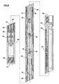
- FIG. 8 is a schematic cross sectional view of such a motor.
- the progressive cavity motor 48 includes a top sub 50 having a fluid inlet 52, an output shaft 54 having a fluid outlet 56, and a power section 58 disposed therebetween.
- the power section includes a stator 60 circumferentially disposed about a rotor 62.
- the rotor 62 has a hollow cavity 64 disposed therethrough that is fluidicly coupled from the inlet 52 to the outlet 56.
- An inlet 66 of the power section portion of the motor 48 allows fluid to flow into a progressive cavity created between the stator 60 and the rotor 62 as the rotor rotates about the stator and to exit an outlet 68 of the power section, as described in reference to Figures 1 and 1A.
- An annulus 70 downstream of the outlet 68 is created between the inner wall of the motor 48 and various components disposed therein, which provide a flow path for the fluid exiting the outlet 68.
- a transfer port 72 is fluidicly coupled from the annulus 70 to a hole 74 disposed in the output shaft 54 and then to the output 56.
- a restrictive port 75 can be formed between the hollow cavity 64 and the annulus 70 to fluidicly couple the hollow cavity 64 to the annulus 70.
- an articulating shaft 76 can be disposed between the rotor 62 and the output shaft 54, so that the output shaft 54 can rotate circumferentially within the motor 48.
- the articulating shaft 76 can include one or more knuckle joints 78 that allow the rotor to precess within the stator with the necessary degrees of freedom.
- a bearing 80 can be disposed on an upper end of an output shaft 54 and a lower bearing assembly 82 can be disposed on a lower end of an output shaft 54.
- One or more seals such as seals 84, 86, assist in sealing fluid from leaking through various joints in the downhole motor 48.
- fluid is flowed down the tubular member 16, shown in Figures 3-7 and enters inlet 52 of the top sub 50.
- a relatively low flow rate such as 10 gallons per minute (0.8 litres per second)
- the flow rate and pressure are insufficient to rotate the rotor 62 within the stator 60 and the fluid stops at inlet 66.
- some fluid flows into the hollow cavity 64 in the rotor 62 and through port 75, into the annulus 70, and eventually through the output 56 of the output shaft 54.
- the flow through the hollow cavity 64 allows various tools located upstream and downstream from the motor to receive flow for indexing, orientation or other functions, as has been described herein.
- the flow rate and/or pressure can be increased to a level at which the rotor 62 rotates within the stator 60 and creates torque on the output shaft 54, so that the motor can rotate downstream tools, such as a cutting tool, as has been described herein.
- the flow through the hollow cavity 64 reaches a maximum rate for a given pressure.
- the flow through the inlet 66 and outlet 68 at greater flow rates and pressures overcome flow through the hollow cavity 64.
- the motor can be activated and deactivated by adjusting the flows without having to retrieve and reset the motor.
- Figure 9 is a schematic cross sectional view of another embodiment of the downhole motor 48. Similar elements in Figure 8 are similarly numbered in Figure 9.
- a top sub 50 having an inlet 52 is coupled to a power section 58 having a stator 60 and rotor 62 that is disposed therein.
- Power section 58 is coupled to an output shaft 54 having an outlet 56.
- a flow path exists between the inlet 52 and an inlet 66 between the stator 60 and the rotor 62, an outlet 62, an annulus 70, a transfer port 72, and a hole 74 that is coupled to the outlet 56.
- fluid is flowed through the inlet 52 at a flow rate and pressure that will force the rotor 62 to rotate within the stator 60. It is known that a percentage of the fluid, at a given pressure and flow rate, can leak through the cavities formed between the stator 60 and the rotor 62, but typically the rotor 62 begins to rotate before a substantial amount of fluid leaks therethrough.
- the rotation of the rotor is restrained by a shear pin 88.
- the shear pin 88 can be disposed in a hole 90 formed through an outer shell 92 of the motor 48 and into the output shaft 54.
- the shear pin can be located at other positions along the motor 48 and the position shown in Figure 9 is merely exemplary.
- the shear pin restrains the output shaft from rotation and allows an increased flow between the progressive cavity formed between the stator 60 and the rotor 62 without the rotor substantially rotating.
- fluid can be flowed through the downhole motor 48 for activation of tools both upstream and downstream of the motor without the motor substantially rotating.
- the fluid flow rate and/or pressure can be increased to a level at which the torque created on the rotor 62 shears the shear pin 88 and allows the rotor to rotate the output shaft 54.
Claims (35)
- Procédé d'actionnement d'un outil de fond (32), comprenant les étapes ci-dessous:accouplement de l'outil de fond à un élément tubulaire (15); l'outil de fond comprenant un outil de mesure de la position;caractérisé par l'accouplement d'un moteur de fond (30) à l'élément tubulaire; etmaintien sélectif du moteur de fond dans un état pratiquement non actionné au cours de l'écoulement d'un fluide à travers le moteur de fond, suffisant pour actionner l'outil de fond; etactionnement de l'outil de fond.
- Procédé selon la revendication 1, dans lequel l'outil de fond (32) est agencé en aval du moteur de fond (30).
- Procédé selon les revendications 1 ou 2, comprenant en outre l'étape d'accroissement de l'écoulement de fluide pour actionner le moteur de fond (30).
- Procédé selon les revendications 1, 2 ou 3, ledit procédé étant utilisé pour couper un trou à un angle par rapport à un puits de forage (10), dans lequel un outil de coupe (22), un sifflet déviateur (20) et un élément d'ancrage (18) sont accouplés à l'élément tubulaire (15); le procédé comprenant en outre l'étape d'actionnement de l'élément d'ancrage.
- Procédé selon la revendication 4, dans lequel l'actionnement de l'élément d'ancrage (18) est effectué pratiquement sans changer l'orientation du sifflet déviateur (20).
- Procédé selon les revendications 4 ou 5, comprenant en outre l'étape de mesure de l'orientation du sifflet déviateur (20) sur place, avant l'actionnement de l'élément d'ancrage (18).
- Procédé selon les revendications 4, 5 ou 6, dans lequel l'élément tubulaire est un tubage enroulé (15).
- Procédé selon l'une quelconque des revendications 4 à 7, comprenant en outre l'étape d'orientation du sifflet déviateur (20) avant d'actionner l'élément d'ancrage (18).
- Procédé selon la revendication 8, comprenant en outre l'étape d'abaissement de la position de l'outil de mesure (32), du moteur de fond (30), de l'outil de coupe (22), du sifflet déviateur (20) et de l'élément d'ancrage (18) dans le puits de forage, l'abaissement dans le puits de forage (10), l'orientation du sifflet déviateur et l'actionnement de l'élément d'ancrage étant effectués dans le cadre d'une seule descente.
- Procédé selon les revendications 8 ou 9, dans lequel l'étape d'orientation du sifflet déviateur (20) comprend l'utilisation d'un élément d'orientation (34) pour orienter le sifflet déviateur.
- Procédé selon la revendication 10, dans lequel l'outil de mesure de la position (32) est agencé entre l'élément d'orientation (34) et le moteur (30).
- Procédé selon l'une quelconque des revendications 4 à 7, comprenant en outre les étapes d'abaissement de l'élément d'ancrage (18) dans le puits de forage (10) et d'actionnement de l'élément d'ancrage dans sa position avant l'abaissement de l'outil de mesure de la position (32), le moteur de fond (30), l'outil de coupe (22) et le sifflet déviateur (20) dans le puits de forage et l'orientation du sifflet déviateur.
- Procédé selon l'une quelconque des revendications 4 à 12, comprenant en outre l'étape d'actionnement du moteur pour faire tourner l'outil de coupe.
- Procédé selon l'une quelconque des revendications 4 à 13, comprenant en outre l'étape de maintien sélectif du moteur (30) dans une position de rotation stationnaire par rapport au sifflet déviateur (20) pendant l'écoulement d'un fluide à travers le moteur et au cours de l'orientation au moins partielle du sifflet déviateur.
- Procédé selon la revendication 14, comprenant en outre l'étape d'écoulement de fluide à travers un arbre de moteur creux (64) du moteur (30).
- Procédé selon la revendication 15, dans lequel l'étape d'écoulement de fluide à travers l'arbre creux de moteur (64) comprend l'écoulement à un premier débit au cours de l'orientation du sifflet déviateur (20) et l'écoulement à un deuxième débit au cours de l'actionnement du moteur en vue de la rotation de l'outil de coupe (22).
- Procédé selon la revendication 14, dans lequel l'étape de maintien sélectif du moteur (30) dans une position de rotation stationnaire comprend le verrouillage d'un arbre de moteur (62) du moteur dans une position non rotative au cours de l'écoulement du fluide à travers le moteur et de l'orientation du sifflet déviateur (20).
- Procédé selon la revendication 17, comprenant en outre l'étape d'application d'un couple suffisant à l'arbre du moteur (62) pour déverrouiller l'arbre du moteur et faire tourner l'outil de coupe (22).
- Procédé selon la revendication 18, comprenant en outre l'étape d'accroissement d'une pression du fluide pour déverrouiller l'arbre du moteur (62).
- Dispositif destiné à être utilisé dans un puits de forage, comprenant:un corps de moteur;un arbre de moteur (62) agencé au moins partiellement à l'intérieur du corps du moteur; etun canal de fluide en communication avec l'arbre du moteur;caractérisé en ce que le dispositif comprend en outre un outil de fond agencé en-dessous du corps du moteur; en ce que l'arbre du moteur est pratiquement non actionné lors de l'écoulement de fluide à travers le corps du moteur pour actionner l'outil de fond; et en ce que le dispositif comprend en outre un outil de mesure de la position (32).
- Dispositif selon la revendication 20, dans lequel l'arbre du moteur (62) comprend un canal (64) formé au moins en partie par l'arbre du moteur, le canal étant accouplé par le fluide à une entrée (52) et une sortie (56) du moteur.
- Dispositif selon la revendication 20, comprenant en outre un élément de cisaillement agencé entre l'arbre du moteur (62) et le corps du moteur.
- Système de coupe d'un trou à un angle par rapport à un puits de forage (10), comprenant:un élément tubulaire (15); etplusieurs composants, englobant l'outil de mesure de la de la position (32), accouplés à l'élément tubulaire;les composants accouplés à l'élément tubulaire englobant un dispositif selon l'une quelconque des revendications 20 à 22.
- Système selon la revendication 23, dans lequel un outil de coupe est accouplé à l'élément tubulaire.
- Système selon la revendication 24, dans lequel les plusieurs composants accouplés à l'élément tubulaire (15) englobent en outre un sifflet déviateur (20) et un élément d'ancrage (18).
- Système selon la revendication 25, dans lequel les composants comprennent en outre un élément d'orientation (34) accouplé à l'élément tubulaire (15).
- Système selon la revendication 26, dans lequel l'élément tubulaire est constitué par un tubage enroulé (15).
- Système selon les revendications 26 ou 27, dans lequel les composants sont agencés dans un ordre allant de l'élément d'orientation (34) au moteur (30), à l'outil de coupe (22) et au sifflet déviateur (20).
- Système selon la revendication 28, dans lequel l'outil de mesure de la position (32) est agencé entre l'élément d'orientation et le moteur.
- Système selon l'une quelconque des revendications 25 à 29, dans lequel l'arbre du moteur (62) est stationnaire en rotation par rapport au sifflet déviateur (20) au cours de l'écoulement d'un fluide à travers le moteur.
- Système selon la revendication 30, dans lequel l'arbre du moteur (62) comprend un arbre de moteur creux (64).
- Système selon la revendication 31, dans lequel l'arbre de moteur creux (64) est dimensionné de sorte à permettre l'écoulement de fluide à travers l'arbre à un premier débit tout en maintenant la position stationnaire en rotation, et à permettre au fluide de faire tourner l'arbre du moteur à un deuxième débit.
- Système selon la revendication 30, dans lequel l'arbre de moteur stationnaire (62) comprend un arbre de moteur verrouillé lors de l'écoulement du fluide à travers le moteur à une première pression, le sifflet déviateur (20) étant partiellement orienté.
- Système selon la revendication 33, comprenant en outre un élément de cisaillement (88) pour verrouiller l'arbre du moteur.
- Système selon la revendication 34, dans lequel l'élément de cisaillement (88) est dimensionné de sorte à cisailler et déverrouiller l'arbre du moteur (62) lorsque la pression du fluide est accrue à une deuxième pression.
Applications Claiming Priority (3)
| Application Number | Priority Date | Filing Date | Title |
|---|---|---|---|
| US09/608,196 US6454007B1 (en) | 2000-06-30 | 2000-06-30 | Method and apparatus for casing exit system using coiled tubing |
| US608196 | 2000-06-30 | ||
| PCT/GB2001/002791 WO2002002903A1 (fr) | 2000-06-30 | 2001-06-22 | Formation d'un trou de forage au moyen d'un tubage spirale |
Publications (2)
| Publication Number | Publication Date |
|---|---|
| EP1295005A1 EP1295005A1 (fr) | 2003-03-26 |
| EP1295005B1 true EP1295005B1 (fr) | 2006-10-25 |
Family
ID=24435473
Family Applications (1)
| Application Number | Title | Priority Date | Filing Date |
|---|---|---|---|
| EP01940834A Expired - Lifetime EP1295005B1 (fr) | 2000-06-30 | 2001-06-22 | Formation d'un trou de forage au moyen d'un tubage spirale |
Country Status (7)
| Country | Link |
|---|---|
| US (2) | US6454007B1 (fr) |
| EP (1) | EP1295005B1 (fr) |
| AU (1) | AU2001274327A1 (fr) |
| CA (1) | CA2409062C (fr) |
| DE (1) | DE60124100T2 (fr) |
| NO (1) | NO325658B1 (fr) |
| WO (1) | WO2002002903A1 (fr) |
Families Citing this family (39)
| Publication number | Priority date | Publication date | Assignee | Title |
|---|---|---|---|---|
| US7311148B2 (en) | 1999-02-25 | 2007-12-25 | Weatherford/Lamb, Inc. | Methods and apparatus for wellbore construction and completion |
| GB9917267D0 (en) * | 1999-07-22 | 1999-09-22 | Smith International | Locking motor shaft |
| US7334650B2 (en) * | 2000-04-13 | 2008-02-26 | Weatherford/Lamb, Inc. | Apparatus and methods for drilling a wellbore using casing |
| US6454007B1 (en) * | 2000-06-30 | 2002-09-24 | Weatherford/Lamb, Inc. | Method and apparatus for casing exit system using coiled tubing |
| US6715567B2 (en) * | 2001-05-02 | 2004-04-06 | Weatherford/Lamb, Inc. | Apparatus and method for forming a pilot hole in a formation |
| US6755248B2 (en) * | 2002-03-28 | 2004-06-29 | Baker Hughes Incorporated | One trip through tubing window milling apparatus and method |
| GB0215659D0 (en) | 2002-07-06 | 2002-08-14 | Weatherford Lamb | Formed tubulars |
| CN1330845C (zh) * | 2002-07-25 | 2007-08-08 | 施蓝姆伯格海外股份有限公司 | 钻凿孔眼方法、微钻钻具和混合式缆绳在该方法中的应用 |
| US6953331B2 (en) * | 2002-08-30 | 2005-10-11 | Extreme Components L.P. | Positioning device with bearing mechanism |
| US7836946B2 (en) | 2002-10-31 | 2010-11-23 | Weatherford/Lamb, Inc. | Rotating control head radial seal protection and leak detection systems |
| GB2394740B (en) * | 2002-11-01 | 2006-03-01 | Smith International | Lockable motor assembly and method |
| GB0226725D0 (en) * | 2002-11-15 | 2002-12-24 | Bp Exploration Operating | method |
| US7650944B1 (en) | 2003-07-11 | 2010-01-26 | Weatherford/Lamb, Inc. | Vessel for well intervention |
| AR042456A1 (es) * | 2003-12-12 | 2005-06-22 | Servicios Especiales San Anton | Dispositivo de pesca autoblocante |
| US8826988B2 (en) | 2004-11-23 | 2014-09-09 | Weatherford/Lamb, Inc. | Latch position indicator system and method |
| US7926593B2 (en) | 2004-11-23 | 2011-04-19 | Weatherford/Lamb, Inc. | Rotating control device docking station |
| US7481282B2 (en) * | 2005-05-13 | 2009-01-27 | Weatherford/Lamb, Inc. | Flow operated orienter |
| CA2616055C (fr) | 2007-01-03 | 2012-02-21 | Weatherford/Lamb, Inc. | Systeme et methodes d'expansion tubulaire |
| US7997345B2 (en) | 2007-10-19 | 2011-08-16 | Weatherford/Lamb, Inc. | Universal marine diverter converter |
| US8286734B2 (en) | 2007-10-23 | 2012-10-16 | Weatherford/Lamb, Inc. | Low profile rotating control device |
| US8844652B2 (en) | 2007-10-23 | 2014-09-30 | Weatherford/Lamb, Inc. | Interlocking low profile rotating control device |
| GB2483825B (en) * | 2008-01-17 | 2012-06-06 | Weatherford Lamb | Flow operated orienter |
| US8540035B2 (en) | 2008-05-05 | 2013-09-24 | Weatherford/Lamb, Inc. | Extendable cutting tools for use in a wellbore |
| EP2840226B1 (fr) | 2008-05-05 | 2023-10-18 | Weatherford Technology Holdings, LLC | Outils actionnés par signal pour le broyage, le forage et/ou des opérations de pêche |
| US9359853B2 (en) | 2009-01-15 | 2016-06-07 | Weatherford Technology Holdings, Llc | Acoustically controlled subsea latching and sealing system and method for an oilfield device |
| US8322432B2 (en) | 2009-01-15 | 2012-12-04 | Weatherford/Lamb, Inc. | Subsea internal riser rotating control device system and method |
| US7971645B2 (en) * | 2009-04-03 | 2011-07-05 | Baker Hughes Incorporated | Four mill bottom hole assembly |
| US8286708B2 (en) * | 2009-05-20 | 2012-10-16 | Schlumberger Technology Corporation | Methods and apparatuses for installing lateral wells |
| US8347983B2 (en) | 2009-07-31 | 2013-01-08 | Weatherford/Lamb, Inc. | Drilling with a high pressure rotating control device |
| US8074749B2 (en) | 2009-09-11 | 2011-12-13 | Weatherford/Lamb, Inc. | Earth removal member with features for facilitating drill-through |
| US8499834B2 (en) * | 2009-10-01 | 2013-08-06 | Baker Hughes Incorporated | Milling tool for establishing openings in wellbore obstructions |
| US8347982B2 (en) | 2010-04-16 | 2013-01-08 | Weatherford/Lamb, Inc. | System and method for managing heave pressure from a floating rig |
| US9175542B2 (en) | 2010-06-28 | 2015-11-03 | Weatherford/Lamb, Inc. | Lubricating seal for use with a tubular |
| WO2012088323A2 (fr) | 2010-12-22 | 2012-06-28 | Weatherford/Lamb, Inc. | Élément d'élimination de terre qui comporte des caractéristiques pour faciliter le forage |
| US9347268B2 (en) * | 2011-12-30 | 2016-05-24 | Smith International, Inc. | System and method to facilitate the drilling of a deviated borehole |
| US9062508B2 (en) * | 2012-11-15 | 2015-06-23 | Baker Hughes Incorporated | Apparatus and method for milling/drilling windows and lateral wellbores without locking using unlocked fluid-motor |
| WO2017086936A1 (fr) * | 2015-11-17 | 2017-05-26 | Halliburton Energy Services, Inc. | Outil multilatéral à passage unique |
| GB2567225B (en) | 2017-10-06 | 2020-02-26 | Priority Drilling Ltd | Directional drilling |
| US20210017854A1 (en) * | 2019-07-15 | 2021-01-21 | Baker Hughes Oilfield Operations Llc | System and method for recovering a slot and forming a whipstock casing exit in a tubular |
Family Cites Families (35)
| Publication number | Priority date | Publication date | Assignee | Title |
|---|---|---|---|---|
| US3463252A (en) * | 1966-09-19 | 1969-08-26 | Smith International | Automatic driller |
| US3896667A (en) * | 1973-10-26 | 1975-07-29 | Texas Dynamatics | Method and apparatus for actuating downhole devices |
| US3908759A (en) | 1974-05-22 | 1975-09-30 | Standard Oil Co | Sidetracking tool |
| FR2332412A1 (fr) | 1975-11-19 | 1977-06-17 | Alsthom Cgee | Dispositif d'immobilisation en rotation de la partie statorique d'un moteur souterrain |
| US4187918A (en) * | 1978-06-12 | 1980-02-12 | Wallace Clark | Down-hole earth drilling motor capable of free circulation |
| US4427079A (en) | 1981-11-18 | 1984-01-24 | Walter Bruno H | Intermittently rotatable down hole drilling tool |
| US4705117A (en) | 1985-11-22 | 1987-11-10 | Amoco Corporation | Method and apparatus for reducing drill bit wear |
| US5363929A (en) * | 1990-06-07 | 1994-11-15 | Conoco Inc. | Downhole fluid motor composite torque shaft |
| US5154231A (en) | 1990-09-19 | 1992-10-13 | Masx Energy Services Group, Inc. | Whipstock assembly with hydraulically set anchor |
| US5186265A (en) * | 1991-08-22 | 1993-02-16 | Atlantic Richfield Company | Retrievable bit and eccentric reamer assembly |
| GB9210846D0 (en) | 1992-05-21 | 1992-07-08 | Baroid Technology Inc | Drill bit steering |
| US5277251A (en) | 1992-10-09 | 1994-01-11 | Blount Curtis G | Method for forming a window in a subsurface well conduit |
| US5287921A (en) * | 1993-01-11 | 1994-02-22 | Blount Curtis G | Method and apparatus for setting a whipstock |
| US5826651A (en) * | 1993-09-10 | 1998-10-27 | Weatherford/Lamb, Inc. | Wellbore single trip milling |
| US5887668A (en) | 1993-09-10 | 1999-03-30 | Weatherford/Lamb, Inc. | Wellbore milling-- drilling |
| US5887655A (en) * | 1993-09-10 | 1999-03-30 | Weatherford/Lamb, Inc | Wellbore milling and drilling |
| US5787978A (en) * | 1995-03-31 | 1998-08-04 | Weatherford/Lamb, Inc. | Multi-face whipstock with sacrificial face element |
| US5472057A (en) | 1994-04-11 | 1995-12-05 | Atlantic Richfield Company | Drilling with casing and retrievable bit-motor assembly |
| US5488989A (en) | 1994-06-02 | 1996-02-06 | Dowell, A Division Of Schlumberger Technology Corporation | Whipstock orientation method and system |
| US5431219A (en) | 1994-06-27 | 1995-07-11 | Dowell, A Division Of Schlumberger Technology Corp. | Forming casing window off whipstock set in cement plug |
| US5443129A (en) | 1994-07-22 | 1995-08-22 | Smith International, Inc. | Apparatus and method for orienting and setting a hydraulically-actuatable tool in a borehole |
| GB9422837D0 (en) | 1994-09-23 | 1995-01-04 | Red Baron Oil Tools Rental | Apparatus for milling a well casing |
| US5725060A (en) * | 1995-03-24 | 1998-03-10 | Atlantic Richfield Company | Mill starting device and method |
| US5551509A (en) * | 1995-03-24 | 1996-09-03 | Tiw Corporation | Whipstock and starter mill |
| US5709265A (en) * | 1995-12-11 | 1998-01-20 | Weatherford/Lamb, Inc. | Wellbore window formation |
| US5738178A (en) | 1995-11-17 | 1998-04-14 | Baker Hughes Incorporated | Method and apparatus for navigational drilling with a downhole motor employing independent drill string and bottomhole assembly rotary orientation and rotation |
| US5947201A (en) | 1996-02-06 | 1999-09-07 | Baker Hughes Incorporated | One-trip window-milling method |
| US5775444A (en) | 1996-10-23 | 1998-07-07 | Falgout, Sr.; Thomas E. | Drill string orienting motor |
| US6109347A (en) | 1997-07-03 | 2000-08-29 | Baker Hughes Incorporated | One-trip, thru-tubing, window-milling system |
| US5944101A (en) * | 1998-06-15 | 1999-08-31 | Atlantic Richfield Company | Apparatus for milling a window in well tubular |
| US6176327B1 (en) * | 1999-05-10 | 2001-01-23 | Atlantic Richfield Company | Method and toolstring for operating a downhole motor |
| GB9917267D0 (en) * | 1999-07-22 | 1999-09-22 | Smith International | Locking motor shaft |
| US6679328B2 (en) * | 1999-07-27 | 2004-01-20 | Baker Hughes Incorporated | Reverse section milling method and apparatus |
| US6454007B1 (en) * | 2000-06-30 | 2002-09-24 | Weatherford/Lamb, Inc. | Method and apparatus for casing exit system using coiled tubing |
| GB2394740B (en) * | 2002-11-01 | 2006-03-01 | Smith International | Lockable motor assembly and method |
-
2000
- 2000-06-30 US US09/608,196 patent/US6454007B1/en not_active Ceased
-
2001
- 2001-06-22 DE DE60124100T patent/DE60124100T2/de not_active Expired - Lifetime
- 2001-06-22 EP EP01940834A patent/EP1295005B1/fr not_active Expired - Lifetime
- 2001-06-22 WO PCT/GB2001/002791 patent/WO2002002903A1/fr active IP Right Grant
- 2001-06-22 CA CA002409062A patent/CA2409062C/fr not_active Expired - Fee Related
- 2001-06-22 AU AU2001274327A patent/AU2001274327A1/en not_active Abandoned
-
2002
- 2002-11-07 NO NO20025332A patent/NO325658B1/no not_active IP Right Cessation
-
2004
- 2004-09-24 US US10/950,223 patent/USRE43054E1/en not_active Expired - Lifetime
Also Published As
| Publication number | Publication date |
|---|---|
| DE60124100T2 (de) | 2007-06-06 |
| NO20025332L (no) | 2002-12-23 |
| NO20025332D0 (no) | 2002-11-07 |
| AU2001274327A1 (en) | 2002-01-14 |
| CA2409062A1 (fr) | 2002-01-10 |
| CA2409062C (fr) | 2007-09-04 |
| EP1295005A1 (fr) | 2003-03-26 |
| DE60124100D1 (de) | 2006-12-07 |
| USRE43054E1 (en) | 2012-01-03 |
| US6454007B1 (en) | 2002-09-24 |
| NO325658B1 (no) | 2008-06-30 |
| WO2002002903A1 (fr) | 2002-01-10 |
Similar Documents
| Publication | Publication Date | Title |
|---|---|---|
| EP1295005B1 (fr) | Formation d'un trou de forage au moyen d'un tubage spirale | |
| US6705413B1 (en) | Drilling with casing | |
| CA2546394C (fr) | Orienteur actionne par ecoulement | |
| US8534379B2 (en) | Apparatus and methods for drilling a wellbore using casing | |
| AU785413B2 (en) | Wireless packer/anchor setting or activation | |
| EP0764234A1 (fr) | Ensemble sifflet deviateur | |
| CA2512641C (fr) | Appareil et procedes permettant de forer un puits utilisant un cuvelage | |
| CA2725717C (fr) | Appareil et procedes permettant de forer un puits utilisant un cuvelage | |
| US20230228170A1 (en) | Whipstock with detachable whipface and sealing capabilities for multilateral systems | |
| US20210246750A1 (en) | One Trip Bottom Hole Assembly and Method for Milling Casing and Directionally Drilling a Lateral Wellbore |
Legal Events
| Date | Code | Title | Description |
|---|---|---|---|
| PUAI | Public reference made under article 153(3) epc to a published international application that has entered the european phase |
Free format text: ORIGINAL CODE: 0009012 |
|
| 17P | Request for examination filed |
Effective date: 20021112 |
|
| AK | Designated contracting states |
Kind code of ref document: A1 Designated state(s): AT BE CH CY DE DK ES FI FR GB GR IE IT LI LU MC NL PT SE TR Designated state(s): AT BE CH CY DE DK ES FI FR GB GR IE IT LI LU MC NL PT SE TR |
|
| AX | Request for extension of the european patent |
Extension state: AL LT LV MK RO SI |
|
| RBV | Designated contracting states (corrected) |
Designated state(s): DE FR GB NL |
|
| 17Q | First examination report despatched |
Effective date: 20050607 |
|
| GRAP | Despatch of communication of intention to grant a patent |
Free format text: ORIGINAL CODE: EPIDOSNIGR1 |
|
| GRAS | Grant fee paid |
Free format text: ORIGINAL CODE: EPIDOSNIGR3 |
|
| GRAA | (expected) grant |
Free format text: ORIGINAL CODE: 0009210 |
|
| AK | Designated contracting states |
Kind code of ref document: B1 Designated state(s): DE FR GB NL |
|
| REG | Reference to a national code |
Ref country code: GB Ref legal event code: FG4D |
|
| REF | Corresponds to: |
Ref document number: 60124100 Country of ref document: DE Date of ref document: 20061207 Kind code of ref document: P |
|
| EN | Fr: translation not filed | ||
| PLBE | No opposition filed within time limit |
Free format text: ORIGINAL CODE: 0009261 |
|
| STAA | Information on the status of an ep patent application or granted ep patent |
Free format text: STATUS: NO OPPOSITION FILED WITHIN TIME LIMIT |
|
| 26N | No opposition filed |
Effective date: 20070726 |
|
| PG25 | Lapsed in a contracting state [announced via postgrant information from national office to epo] |
Ref country code: FR Free format text: LAPSE BECAUSE OF FAILURE TO SUBMIT A TRANSLATION OF THE DESCRIPTION OR TO PAY THE FEE WITHIN THE PRESCRIBED TIME-LIMIT Effective date: 20070608 |
|
| PG25 | Lapsed in a contracting state [announced via postgrant information from national office to epo] |
Ref country code: FR Free format text: LAPSE BECAUSE OF FAILURE TO SUBMIT A TRANSLATION OF THE DESCRIPTION OR TO PAY THE FEE WITHIN THE PRESCRIBED TIME-LIMIT Effective date: 20061025 |
|
| REG | Reference to a national code |
Ref country code: NL Ref legal event code: SD Effective date: 20150318 |
|
| REG | Reference to a national code |
Ref country code: DE Ref legal event code: R081 Ref document number: 60124100 Country of ref document: DE Owner name: WEATHERFORD TECHNOLOGY HOLDINGS, LLC, HOUSTON, US Free format text: FORMER OWNER: WEATHERFORD/LAMB, INC., HOUSTON, TEX., US Effective date: 20150417 |
|
| REG | Reference to a national code |
Ref country code: GB Ref legal event code: 732E Free format text: REGISTERED BETWEEN 20151022 AND 20151028 |
|
| PGFP | Annual fee paid to national office [announced via postgrant information from national office to epo] |
Ref country code: GR Payment date: 20170630 Year of fee payment: 17 |
|
| PGFP | Annual fee paid to national office [announced via postgrant information from national office to epo] |
Ref country code: NL Payment date: 20170614 Year of fee payment: 17 |
|
| PGFP | Annual fee paid to national office [announced via postgrant information from national office to epo] |
Ref country code: GB Payment date: 20180403 Year of fee payment: 18 |
|
| REG | Reference to a national code |
Ref country code: DE Ref legal event code: R119 Ref document number: 60124100 Country of ref document: DE |
|
| REG | Reference to a national code |
Ref country code: NL Ref legal event code: MM Effective date: 20180701 |
|
| PG25 | Lapsed in a contracting state [announced via postgrant information from national office to epo] |
Ref country code: NL Free format text: LAPSE BECAUSE OF NON-PAYMENT OF DUE FEES Effective date: 20180701 |
|
| PG25 | Lapsed in a contracting state [announced via postgrant information from national office to epo] |
Ref country code: DE Free format text: LAPSE BECAUSE OF NON-PAYMENT OF DUE FEES Effective date: 20190101 |
|
| GBPC | Gb: european patent ceased through non-payment of renewal fee |
Effective date: 20190622 |
|
| PG25 | Lapsed in a contracting state [announced via postgrant information from national office to epo] |
Ref country code: GB Free format text: LAPSE BECAUSE OF NON-PAYMENT OF DUE FEES Effective date: 20190622 |