EP1294532B1 - Burr removal apparatus - Google Patents
Burr removal apparatus Download PDFInfo
- Publication number
- EP1294532B1 EP1294532B1 EP01950695A EP01950695A EP1294532B1 EP 1294532 B1 EP1294532 B1 EP 1294532B1 EP 01950695 A EP01950695 A EP 01950695A EP 01950695 A EP01950695 A EP 01950695A EP 1294532 B1 EP1294532 B1 EP 1294532B1
- Authority
- EP
- European Patent Office
- Prior art keywords
- abrasive
- workpiece
- shaft
- abrasive mechanism
- access device
- Prior art date
- Legal status (The legal status is an assumption and is not a legal conclusion. Google has not performed a legal analysis and makes no representation as to the accuracy of the status listed.)
- Expired - Lifetime
Links
- 230000007246 mechanism Effects 0.000 claims abstract description 268
- 238000005299 abrasion Methods 0.000 claims abstract description 6
- 239000003082 abrasive agent Substances 0.000 claims description 24
- 230000008878 coupling Effects 0.000 claims description 20
- 238000010168 coupling process Methods 0.000 claims description 20
- 238000005859 coupling reaction Methods 0.000 claims description 20
- 238000000034 method Methods 0.000 claims description 17
- 230000001681 protective effect Effects 0.000 abstract description 15
- 239000012634 fragment Substances 0.000 abstract description 2
- 239000000463 material Substances 0.000 description 27
- 229910052751 metal Inorganic materials 0.000 description 10
- 239000002184 metal Substances 0.000 description 10
- 238000009991 scouring Methods 0.000 description 7
- 230000004048 modification Effects 0.000 description 6
- 238000012986 modification Methods 0.000 description 6
- 239000005060 rubber Substances 0.000 description 5
- 150000002739 metals Chemical class 0.000 description 3
- 239000004033 plastic Substances 0.000 description 3
- 230000007423 decrease Effects 0.000 description 2
- -1 for example Substances 0.000 description 2
- 230000001788 irregular Effects 0.000 description 2
- 238000003801 milling Methods 0.000 description 2
- 238000005498 polishing Methods 0.000 description 2
- 238000003860 storage Methods 0.000 description 2
- 229910052580 B4C Inorganic materials 0.000 description 1
- 229910052582 BN Inorganic materials 0.000 description 1
- PZNSFCLAULLKQX-UHFFFAOYSA-N Boron nitride Chemical compound N#B PZNSFCLAULLKQX-UHFFFAOYSA-N 0.000 description 1
- 229920001875 Ebonite Polymers 0.000 description 1
- 229910000677 High-carbon steel Inorganic materials 0.000 description 1
- 239000004677 Nylon Substances 0.000 description 1
- 229910000831 Steel Inorganic materials 0.000 description 1
- RTAQQCXQSZGOHL-UHFFFAOYSA-N Titanium Chemical compound [Ti] RTAQQCXQSZGOHL-UHFFFAOYSA-N 0.000 description 1
- 230000009471 action Effects 0.000 description 1
- PNEYBMLMFCGWSK-UHFFFAOYSA-N aluminium oxide Inorganic materials [O-2].[O-2].[O-2].[Al+3].[Al+3] PNEYBMLMFCGWSK-UHFFFAOYSA-N 0.000 description 1
- 230000008901 benefit Effects 0.000 description 1
- INAHAJYZKVIDIZ-UHFFFAOYSA-N boron carbide Chemical compound B12B3B4C32B41 INAHAJYZKVIDIZ-UHFFFAOYSA-N 0.000 description 1
- 238000005219 brazing Methods 0.000 description 1
- 230000008859 change Effects 0.000 description 1
- 238000006243 chemical reaction Methods 0.000 description 1
- 229910003460 diamond Inorganic materials 0.000 description 1
- 239000010432 diamond Substances 0.000 description 1
- 238000009499 grossing Methods 0.000 description 1
- 230000009191 jumping Effects 0.000 description 1
- 239000007788 liquid Substances 0.000 description 1
- 238000004519 manufacturing process Methods 0.000 description 1
- 229920001778 nylon Polymers 0.000 description 1
- 239000007787 solid Substances 0.000 description 1
- 239000010935 stainless steel Substances 0.000 description 1
- 229910001220 stainless steel Inorganic materials 0.000 description 1
- 239000010959 steel Substances 0.000 description 1
- 239000004575 stone Substances 0.000 description 1
- 239000010936 titanium Substances 0.000 description 1
- 229910052719 titanium Inorganic materials 0.000 description 1
- WFKWXMTUELFFGS-UHFFFAOYSA-N tungsten Chemical compound [W] WFKWXMTUELFFGS-UHFFFAOYSA-N 0.000 description 1
- 229910052721 tungsten Inorganic materials 0.000 description 1
- 239000010937 tungsten Substances 0.000 description 1
- UONOETXJSWQNOL-UHFFFAOYSA-N tungsten carbide Chemical compound [W+]#[C-] UONOETXJSWQNOL-UHFFFAOYSA-N 0.000 description 1
- 238000003466 welding Methods 0.000 description 1
- 239000002023 wood Substances 0.000 description 1
Images





Classifications
-
- B—PERFORMING OPERATIONS; TRANSPORTING
- B23—MACHINE TOOLS; METAL-WORKING NOT OTHERWISE PROVIDED FOR
- B23B—TURNING; BORING
- B23B51/00—Tools for drilling machines
- B23B51/10—Bits for countersinking
- B23B51/101—Deburring tools
-
- B—PERFORMING OPERATIONS; TRANSPORTING
- B24—GRINDING; POLISHING
- B24D—TOOLS FOR GRINDING, BUFFING OR SHARPENING
- B24D13/00—Wheels having flexibly-acting working parts, e.g. buffing wheels; Mountings therefor
- B24D13/20—Mountings for the wheels
-
- B—PERFORMING OPERATIONS; TRANSPORTING
- B24—GRINDING; POLISHING
- B24B—MACHINES, DEVICES, OR PROCESSES FOR GRINDING OR POLISHING; DRESSING OR CONDITIONING OF ABRADING SURFACES; FEEDING OF GRINDING, POLISHING, OR LAPPING AGENTS
- B24B9/00—Machines or devices designed for grinding edges or bevels on work or for removing burrs; Accessories therefor
- B24B9/007—Machines or devices designed for grinding edges or bevels on work or for removing burrs; Accessories therefor for end faces of tubes
-
- B—PERFORMING OPERATIONS; TRANSPORTING
- B24—GRINDING; POLISHING
- B24D—TOOLS FOR GRINDING, BUFFING OR SHARPENING
- B24D13/00—Wheels having flexibly-acting working parts, e.g. buffing wheels; Mountings therefor
- B24D13/02—Wheels having flexibly-acting working parts, e.g. buffing wheels; Mountings therefor acting by their periphery
- B24D13/10—Wheels having flexibly-acting working parts, e.g. buffing wheels; Mountings therefor acting by their periphery comprising assemblies of brushes
-
- B—PERFORMING OPERATIONS; TRANSPORTING
- B24—GRINDING; POLISHING
- B24D—TOOLS FOR GRINDING, BUFFING OR SHARPENING
- B24D99/00—Subject matter not provided for in other groups of this subclass
-
- F—MECHANICAL ENGINEERING; LIGHTING; HEATING; WEAPONS; BLASTING
- F16—ENGINEERING ELEMENTS AND UNITS; GENERAL MEASURES FOR PRODUCING AND MAINTAINING EFFECTIVE FUNCTIONING OF MACHINES OR INSTALLATIONS; THERMAL INSULATION IN GENERAL
- F16F—SPRINGS; SHOCK-ABSORBERS; MEANS FOR DAMPING VIBRATION
- F16F15/00—Suppression of vibrations in systems; Means or arrangements for avoiding or reducing out-of-balance forces, e.g. due to motion
- F16F15/30—Flywheels
-
- Y—GENERAL TAGGING OF NEW TECHNOLOGICAL DEVELOPMENTS; GENERAL TAGGING OF CROSS-SECTIONAL TECHNOLOGIES SPANNING OVER SEVERAL SECTIONS OF THE IPC; TECHNICAL SUBJECTS COVERED BY FORMER USPC CROSS-REFERENCE ART COLLECTIONS [XRACs] AND DIGESTS
- Y10—TECHNICAL SUBJECTS COVERED BY FORMER USPC
- Y10T—TECHNICAL SUBJECTS COVERED BY FORMER US CLASSIFICATION
- Y10T29/00—Metal working
- Y10T29/51—Plural diverse manufacturing apparatus including means for metal shaping or assembling
- Y10T29/5182—Flash remover
-
- Y—GENERAL TAGGING OF NEW TECHNOLOGICAL DEVELOPMENTS; GENERAL TAGGING OF CROSS-SECTIONAL TECHNOLOGIES SPANNING OVER SEVERAL SECTIONS OF THE IPC; TECHNICAL SUBJECTS COVERED BY FORMER USPC CROSS-REFERENCE ART COLLECTIONS [XRACs] AND DIGESTS
- Y10—TECHNICAL SUBJECTS COVERED BY FORMER USPC
- Y10T—TECHNICAL SUBJECTS COVERED BY FORMER US CLASSIFICATION
- Y10T409/00—Gear cutting, milling, or planing
- Y10T409/30—Milling
- Y10T409/3042—Means to remove scale or raised surface imperfection
- Y10T409/304256—Means to remove flash or burr
Definitions
- This invention relates to removal of burrs and similar unwanted projections from metals and other relatively hard materials.
- burrs Removal of undesirable projections (collectively referred to as "burrs" herein) from a surface, such as a metal or other relatively hard material, is extremely important in the metal finishing industry.
- the presence of an umemoved burr on the surface of a part can cause numerous problems such as, for example, interference with the flow of a liquid or difficulty with the positioning of electrical charge-carrying lines.
- burr removal can be very difficult due to the location of the surface containing burrs (referred to herein as a "burred surface").
- a burred surface will often have an irregular shape that makes burr removal very cumbersome and time consuming using existing burr removal tools. For example, when two intersecting apertures are drilled into a part, the breakthrough of the second aperture into the first aperture will produce a burred surface that is non-planar and is ellipsoid in shape. Due to the location and shape of this burred surface, the burrs located thereon cannot be easily abraded with a conventional burr removal tool.
- Another significant problem is the unintentional scouring or gouging of a surface that may result during the advancement of a burr removal tool toward a burred surface.
- a burr removal tool when a burr removal tool is advanced through an aperture to remove a burr located within a part, the abrasive surface of the tool may inadvertently contact the wall of the aperture as the tool is advanced through the aperture, thereby removing material that is preferably left intact. Damage may also result when the rotating abrasive surface binds against a burr or other irregularity on the surface of the part and causes the tool to jump laterally or move in another uncontrollable manner.
- burr removal arises when it is necessary to use two or more different burr removal tools within a small space in a single container or housing. This commonly occurs when rough burr removal is to be followed by finishing, each requiring a different burr removal material or tool shape. Similarly, this difficult exists when a container includes two or more different materials, each with a burred surface that requires its own burr removal mechanism and associated material.
- the preferred embodiments of the present apparatus provide a new and improved burr removal tool that is adapted to abrade surfaces on a workpiece that have been very difficult to access heretofore.
- the preferred embodiments also provide an apparatus for protecting the surface of a workpiece from unintentional scouring or damaging as the tool is advanced into position and/or jumps laterally due to binding or slippage.
- the burr removal tool generally comprises an access device (e.g., a working shaft), an abrasive surface and a non-abrasive member.
- the abrasive surface has a cross-sectional profile that is greater in size than the access device.
- the non-abrasive member has a cross-sectional profile that is greater in size than the abrasive surface.
- the non-abrasive member is adapted to protect the workpiece from the abrasive surface as the tool is advanced toward a burr.
- the non-abrasive member prevents the abrasive surface from inadvertently contacting and abrading the workpiece and is therefore particularly useful when advancing the tool through a small opening (e.g., an aperture) or in situations wherein it is difficult to maintain the tool in a steady position.
- a significant advantage of the burr removal tool is the ability of the abrasive mechanism to selectively abrade surfaces that may be irregular in shape or are located in difficult regions within a workpiece. Although the tool is described with respect to burr removal, the tool may also be used for abrading a wide variety of other surfaces.
- a burr removal apparatus comprising:
- the abrasive mechanism is approximately cylindrically symmetric in shape and has an exposed abrasive surface (preferably with Mohs hardness at least about 5.5).
- the non-abrasive member is made of a relatively non-abrasive material (preferably with Mohs hardness much less than 5.5) for protecting the surface from undesirable scouring or gouging.
- the non-abrasive member may be mounted on the abrasive mechanism or on the working shaft.
- the non-abrasive member is mounted distal to the abrasive mechanism and has an outer perimeter that is circular in shape.
- the non-abrasive member may be provided in the form of a collar that extends around an exterior of the abrasive mechanism.
- the working shaft is deflectable and can be bent or deformed or tilted as the shaft rotates to help expose the abrasive mechanism to a burred surface.
- a relatively inflexible working shaft is attached to a flexible coupling member.
- the flexible coupling member allows the working shaft to deflect and therefore facilitates access to regions within a part that are difficult or impossible to reach with conventional tools.
- the flexible coupling member also may be used to apply a bias force on the abrasive mechanism to improve and ensure smooth and consistent contact with a burred surface during burr removal.
- the flexible coupling member may be formed of a flexible material, such as rubber, or may be mechanical, such as a flexible spring or a flexible chuck.
- at least a portion of the working shaft is formed of a flexible material that allows the distal portion of the working shaft to bend.
- the burr removal tool includes two or more different abrasive mechanisms on a single working shaft. This aspect allows for the removal of burrs and finishing of the surface without exchanging tools.
- the burr removal apparatus is sized to be small and versatile enough to permit the rapid interchange of one type of abrasive mechanism with another within a small space or aperture.
- the cross-sectional shape of the abrasive mechanism is formed to minimize undesirable removal of adjacent material from the surface of a workpiece.
- Various cross-sections of the abrasive mechanism may include ovular, quadrilateral, trapezoidal or polygonal.
- a shaft restrictor is provided to control or prevent lateral excursions of the rotating working shaft. This aspect prevents the abrasive mechanism from jumping or wobbling and thereby protects the workpiece against inadvertent removal of material and ensures smooth movement of the abrasive mechanism.
- the shaft is provided with an additional rotatable mass (e.g. flywheel) that maintains the angular velocity of the shaft in the presence of factional forces, even after a rotational drive mechanism for the shaft is turned off or disconnected.
- an additional rotatable mass e.g. flywheel
- two or more approximately cylindrically symmetric abrasive mechanisms are separated by a space or by a non-abrasive collar and are attached to a rotatable shaft.
- each of the abrasive mechanisms includes a different abrasive material or a different roughness or grade of the same material. Therefore, the same burr removal apparatus can be applied to different surfaces or materials without removing the burr removal apparatus to change the abrasive mechanism.
- the abrasive mechanism comprises a brush having one or more projections or bristles attached to and extending radially from the working shaft.
- the projections may be formed of an abrasive material or, alternatively, each of the projections may be formed with an abrasive nodule at the tip.
- the preferred embodiments also provide a burr removal tool that is safe, reliable, convenient to use and inexpensive to manufacture.
- a method for removing a burr from an edge of a workpiece comprising:
- the workpiece having the burred surface located thereon may be deburred by rotating the workpiece instead of, or independently of, the access device.
- FIGS 1A and 1B illustrate a first preferred embodiment of a burr removal apparatus 10 in accordance with the present invention.
- the apparatus 10 includes a drive shaft 12, a flexible coupling member 14, a working shaft 16, an approximately cylindrically symmetric abrasive mechanism 18 concentrically attached to the distal end of the working shaft 16, and a non-abrasive member in the form of a collar 20.
- the entire apparatus 10 is caused to rotate, for example, using a shaft driver (rotator) mechanism 21, such as a motor, that is coupled to the proximal end of the drive shaft 12.
- a shaft driver (rotator) mechanism 21 such as a motor
- the collar 20 is mounted on the distal end of the abrasive mechanism 18 and is made of a non-abrasive material that will not significantly abrade the surface of the workpiece.
- the purpose of the collar 20 is to protect the surface of a workpiece from unintentional scouring or gouging as the burr removal apparatus 10 is advanced along or through the workpiece toward a burred surface.
- the collar 20 may be coupled to the abrasive mechanism 18 by any suitable means, such as, for example, brazing, welding or mechanically connected (e.g. snap-on).
- non-abrasive members may be used in place of the collar white still achieving the desired purpose of protecting the workpiece. Any type of non-abrasive member will suffice wherein the non-abrasive member has a diameter that is greater than the diameter of the abrasive mechanism.
- the non-abrasive member may be mounted to the shaft rather than to the abrasive mechanism.
- the non-abrasive member may be coupled to the apparatus via a bearing mechanism, such that the non-abrasive member does not rotate along with the abrasive mechanism.
- the abrasive mechanism 18 includes an abrasive surface adapted to remove burrs or other unwanted material from the surface of a workpiece.
- the abrasive mechanism 18 is shown having a hemi-spherical shape that is particularly well-suited for removing burrs that are located at the intersection of two circular apertures within a workpiece. It will be appreciated, however, that other types and shapes of abrasive mechanisms may be used with the present apparatus.
- the flexible coupling member 14 can be made of any suitable material, such as, for example, rubber.
- the purpose of the flexible coupling member 14 is to transfer torque from the drive shaft 12 to the working shaft 16 while providing the working shaft 16 with the ability to deflect relative to the drive shaft 12, as illustrated in Figure 1B.
- the embodiment of the flexible coupling member 14 illustrated in Figure 1A is formed with a hollow core 22 (i.e. a lumen) extending lengthwise therethrough.
- a first bushing 24 is located in the distal end of the core 22 for housing the proximal end of the working shaft 16.
- a first set screw 26 is provided for maintaining the working shaft 16 in the first bushing 24.
- a second bushing 28 is located in the proximal end of the core 22 for housing the distal end of the drive shaft 12.
- a second set screw 30 is provided for maintaining the drive shaft 12 in the second bushing 28.
- the set screws 26, 30 may be loosened to remove one or both of the shafts from the bushings 24, 28 to interchange parts as desired for
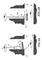
- Figures 2A and 2B illustrate one preferred use of the embodiment of the apparatus just described for removing burrs in a relatively inaccessible space.
- Figures 2A illustrates the working shaft 16 as it is being advanced into position through an aperture or opening for deburring an edge 30B of the aperture at a location where two apertures intersect in a workpiece 30.
- the non-abrasive collar 20 prevents the rotating abrasive mechanism 18 from scouring, gouging or otherwise removing materials from the wall 30A of the aperture during advancement.
- the working shaft 16 is deflected relative to the wall 30A due to a lateral force applied to the collar 20 by contact with the wall 30A of the aperture.
- the rotating abrasive mechansim 18 contacts the edge of the aperture 30B containing burrs.
- the abrasive mechanism 18 rides along the edge 30B until all the burrs located thereon are removed.
- this procedure is performed while rotating the workpiece around a central axis of the aperture (as shown by the lower arrows). The workpiece is rotated such that the abrasive mechanism contacts the entire edge of the aperture.
- the curved outer surface of the abrasive mechanism 18 has a cross-sectional shape that is formed to assure that the burrs located on the edge 30B are completely abraded as the workpiece is rotated.
- the abrasive mechanism need not be approximately cylindrically symmetric and/or the working shaft need not be approximately concentrically attached to the abrasive mechanism.
- the working shaft need not be an elongated cylindrical member. Any apparatus capable of transmitting torque to the abrasive mechanism is intended to be within the scope of this invention.
- FIGS 3A through 5B illustrate various exemplary methods for removing burrs from the edge of an exit hole 34 in a workpiece 32 using the embodiment of the present apparatus illustrated with reference to Figures 1A and 1B. Each of these methods achieves the desired result of abrading the entire inner edge of the circular exit hole 34.
- Figures 3A and 3B illustrate a first method wherein the abrasive mechanism 18 rotates in a fixed location about a stationary axis. While the abrasive mechanism 18 rotates, the workpiece 32 also rotates, preferably in the opposite direction, about an axis that is off center from the axis of rotation of the abrasive mechanism 18.
- Figure 3A shows the abrasive mechanism 18 in a first position relative to the workpiece 32.
- Figure 3B shown the workpiece 32 after being rotated approximately 45 degrees. With the workpiece 32 in this new position, the abrasive mechanism 18 is located at a different relative location within the exit hole 34.
- a lathe may be used in this method to facilitate gripping and rotating the workpiece 32, or the tool, or both.
- Figures 4A and 4B illustrate a second method for deburring the edge of an exit hole 34 in a workpiece 32. Using this method, the workpiece 32 is held stationary while the axis of rotation of the abrasive mechanism 18 is moved around the exit hole 34.
- Figure 4A illustrates the abrasive mechanism in a first position relative to the exit hole 34.
- Figure 4B illustrates the abrasive mechanism after the abrasive mechanism 18 has been moved to a different location such that it is in contact with a different region of the edge of the exit hole 34.
- Figures 5A and 5B illustrate yet another method for deburring the edge of an exit hole 34 in a workpiece 32.
- the axis of rotation of the abrasive mechanism 18 is stationary, however, the workpiece is moved laterally in an X-Y plane using, for example, a milling machine.
- Figure 5A illustrates the abrasive mechanism 18 in a first position relative to the exit hole 34.
- Figure 5B shows the workpiece 32 after being moved in the X-Y plane to a new location such that the abrasive mechanism 18 contacts a different region of the edge of the exit hole 34.
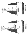
- FIGS 6A and 6B schematically illustrate in further detail the distal end portion of the burr removal apparatus described previously with reference to Figures 1A and 1B.
- the working shaft 16 is relatively inflexible and extends from the distal end of a flexible rubber (or other deformable material) coupling member 14.
- An abrasive mechanism 18 with a collar 20 mounted thereon is fixedly attached to the distal end of the shaft 16.
- the flexible coupling member 14 allows the working shaft 16 to deflect as the wall 30A of the workpiece 30 exerts a lateral force on the collar 20, as illustrated in Figure 6A.
- the deflection of the working shaft 16 allows additional force to be applied in encouraging the abrasive mechanism 18 to contact the portion 30B of the workpiece 30 that is to be deburred.
- the flexible coupling member 14 exerts a reaction force which increases the surface contact as the abrasive mechanism 18 rides along the corner 30B of the workpiece 30, as illustrated in Figure 6B.
- FIGs 7A and 7B illustrate a first modification of a working shaft in accordance with another preferred embodiment of the present invention.
- This embodiment comprises a relatively inflexible rotatable working shaft portion 38, an abrasive mechanism 18, and a flexible shaft portion 36 positioned between and connected to the inflexible working shaft portion 38 and the abrasive mechanism 18.
- the flexible shaft portion 36 is a flexible joint or spring that allows the abrasive mechanism to deflect relative to the inflexible shaft 38, as shown in Figure 7A.
- a collar 20 of non-abrasive material extends laterally beyond the abrasive mechanism 18 to prevent the side wall 30A from scouring or gouging when the abrasive mechanism 18 is being moved into place or is being removed from a region adjacent to the workpiece 30.
- the spring 36 exerts a force that encourages the abrasive mechanism 18 to contact and ride along the corner 30B, as shown in Figure 7B.
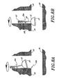
- Figures 8A and 8B illustrate a second modification of a working shaft in accordance with another preferred embodiment of the present invention.
- a rotatable inflexible shaft portion 40 may be positioned between a flexible shaft portion 42 arid an abrasive mechanism 18 with a collar 20 mounted thereon.
- Figure 8A illustrates the device as the abrasive mechanism 18 is advanced along a side wall 30A in an aperture of a workpiece 30.
- Figure 8B illustrates the device as the abrasive mechanism 18 is advanced around the corner 30B of the workpiece 30.
- the shaft may have a hollow core that partly or fully surrounds the spring.
- a shaft core may include one, or more than one, spring.
- a shaft core may include a flexible shaft portion and a substantially inflexible shaft portion.
- the non-abrasive member may be a substantially annular disk (i.e., a collar) or may be a substantially solid disk (i.e., a plate).
- Figures 9A and 9B illustrate a third modification of a working shaft in accordance with another preferred embodiment of the present invention.
- the working shaft 44 is relatively flexible.
- the shaft may be formed of any suitable material including, for example, a steel cable, a coiled spring, and a hard rubber.
- Figure 9A illustrates a workpiece 30 with an aperture having a side wall 30A.
- the workpiece 30 is rotating about the center line of the aperture at a first angular velocity 1.
- the rotatable shaft 44 with abrasive mechanism 18 and collar 20 is advanced along the center line of the aperture in the workpiece 30.
- the working shaft 44 is rotating at a second angular velocity 2.
- the workpiece 30 and the abrasive mechanism 18 are rotating in opposite circumferential directions (e.g., clockwise and counterclockwise, respectively) with angular velocities specifically chosen for the particular application.
- both the workpiece 30 and the abrasive mechanism 18 may be rotating in the same direction with different angular velocities (1- 2).
- rotation of the substantial mass of the abrasive mechanism 18 at the distal end of the working shaft 44 will inevitably produce some asymmetry in the rotational position of the abrasive mechanism 18.
- This asymmetry causes the distal end of the working shaft 44 to differ in direction and/or in its lateral location relative to the proximal end of the shaft.
- the abrasive mechanism 18 will "wobble” as it spins and will eventually come into contact with a side wall 30A of the workpiece 30.
- the working shaft 44 is then advanced further through the aperture such that the abrasive mechanism 18 "wobbles" around the opening in the aperture to remove burrs along the corner 30B.
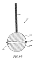
- Figure 10 illustrates the distal end portion 100 of a burr removal apparatus in accordance with another preferred embodiment of the present invention.
- a working shaft 116 preferably inflexible, is attached to a first approximately cylindrically symmetric abrasive mechanism 118A, and the shaft and/or the first abrasive mechanism is attached or connected to a second approximately cylindrically symmetric mechanism 118B.
- the first and second abrasive mechanisms, 118A and 118B are spaced apart by a groove 114, or by empty space if desired.
- a non-abrasive collar or snap ring 120 is positioned between, or adjacent to, the first and second abrasive mechanisms, 118A and 118B.
- the first and second abrasive mechanisms, 118A and 118B may be formed with the same abrasive material or different abrasive materials, as desired.
- the first abrasive mechanism 118A and the second abrasive mechanism 118B may be used for different purposes on the same workpiece.
- the second abrasive mechanism 118B may be used for rough burr removal from a surface and the first abrasive mechanism 118A may be used for smoothing and finishing of the same or different surface.
- the second abrasive mechanism 118B serves another purpose.
- the second abrasive mechanism 118B may be rotated and advanced to remove, or reduce the size of, the projections so that the tool can be moved to its desired location within the aperture.
- the first abrasive mechanism 118A can be used for a similar purpose when the tool is moving in the opposite direction through a workpiece.
- the collar 120 between the first and second abrasive mechanisms, 118A and 118B protects a surface from unintentional scouring and gouging.
- the collar 120 also ensures that a surface is exposed to at most one of the two abrasive mechanisms, 118A or 118 at any one time.
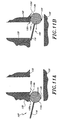
- FIGS 11A and 11B One preferred use of this embodiment 100 is illustrated in Figures 11A and 11B.
- the distal end portion 100 of the burr removal tool is inserted into an aperture or hole such that the collar 120 rides along the wall 130A of a workpiece 130, as illustrated in Figure 11B and shown by the arrow.
- the first abrasive mechanism 118A comes into contact with the comer 130B to remove burrs located thereon.
- the distal end portion 100 may then be advanced further into the aperture until the collar 120 is located distal to the corner 130C of the workpiece 130.
- the device is then retracted such that the collar 120 rides along the wall 130D of the workpiece 130, as illustrated in Figure 11B and shown by the arrow.
- the second abrasive mechanism 118B comes into contact with the corner 130C to remove burrs located thereon. It will be appreciated that the removal of burrs from corner 130C would not be possible without the second abrasive mechanism 118B unless the tool was inserted from the opposite direction. Therefore, this embodiment of the present invention advantageously allows for the removal of burrs in a workpiece by entry into the aperture from either direction.
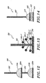
- Figure 12 illustrates the distal end portion 200 of a burr removal apparatus in accordance with another preferred embodiment of the present invention.
- This apparatus includes a first shaft 202 and a second shaft 204, with one or both of the shafts preferably being inflexible and preferably being approximately concentric.
- the first and second shafts, 202 and 204 are parts of a single, unitary shaft.
- One or both of the shafts, 202 and 204 are attached or connected to a first abrasive mechanism 218A, which has a first non-abrasive collar 220A.
- the second shaft 204 is attached or connected to a second abrasive mechanism 218B that is contiguous to or spaced apart from the first abrasive mechanism 218A and that has a second non-abrasive collar 220B.
- the first and second abrasive mechanisms, 220A and 220B may have the same abrasive materials or may have different abrasive materials.
- This embodiment may be used to provide two different abrasive materials on a single tool. By having two types of abrasive materials on a single tool, two different types of abrasion can be performed, such as, for example, burr removal and polishing without changing the tool. This embodiment may also be used to abrade two different types of surfaces on a workpiece which each require different abrasive materials.
- FIG. 13 illustrates the distal end portion 300 of a burr removal apparatus in accordance with another preferred embodiment of the present invention wherein an abrasive brush is used for burr removal.
- a rotatable shaft 302 is provided with a plurality of laterally oriented rods or projections, 304-1, 304-2 and 304-3, that are anchored in, and extend horizontally or diagonally outwardly from, the shaft.
- Each of the projections, 304-1, 304-2 and 304-3 has an abrasive nodule, 306-1, 306-2 and 306-3, respectively, mounted at or near the end.
- one or more of the abrasive nodules, 306-1, 306-2 and 306-3 is caused to move outwardly by centrifugal force, to contact a burred surface and to thereby remove one or more burrs from the burred surface.
- This contact may occur because centrifugal force exerted on the nodules by the shaft rotation causes one or more of the projections, 304-1, 304-2 and 304-3, to bend.
- each projection appraaches an angle of 90 degrees rotative to the shaft 302 and the corresponding nodules 306-1, 306-2 and 306-3 move as far as possible from the shaft 302.
- a protective collar 308 is provided at the distal end of the working shaft 302 which prevents the abrasive nodules, 306-1, 306-2 and 306-3 from contacting the surface of the workpiece as the distal end portion 300 is advanced along or through the workpiece.
- the abrasive nodules 308-1, 306-2 and 306-3 are located such that they contact the workpiece only after the collar 308 has been advanced over a corner of a workpiece such that they can move laterally into contact with the workpiece.
- the abrasive brush is formed projections that have no abrasive nodules at the tips.
- the projections are abrasive mechanisms themselves and are made of any suitable material such as, for example, stainless steel or nylon.
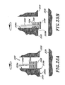
- FIGS 25A and 25B illustrate another alternative embodiment of the apparatus wherein a cylindrically-shaped abrasive brush 2500 is provided at the distal end of a working shaft 2502.
- This type of brush is commonly referred to as a "wide-face brush” or a "cylinder brush.”
- the brush 2500 includes a plurality of projections 2504 extending radially outward from the working shaft 2502. Each of the projections 2504 is preferably formed with abrasive nodules 2506 at the tips.
- a protective collar 2508 is provided at the distal end of the working shaft 2502 with an outer diameter that is larger than the outer diameter of the brush 2500.
- the abrasive nodules 2506 do not contact the wall 2530A of the workpiece 2530 while the brush 2500 is advanced through an aperture, as illustrated in Figure 25A.
- the abrasive nodules 2506 come into contact with the workpiece 2530.
- some abrasive nodules may extend around the comer 2530B to contact wall 2530C, thereby removing all burrs located in the region of the corner 2530B.
- the brush 2500 illustrated in Figures 25A and 25B may be formed without abrasive nodules wherein the projections are abrasive mechanisms themselves.
- a second collar (not shown) may be provided proximal to the projections of the brush illustrated previously in Figures 13, 25A and 25B.
- the second collar may be smaller in diameter than the outermost diameter of the abrasive nodules for limiting the abrasion performed on a workpiece.
- FIG 14 illustrates the distal end portion 400 of a burr removal apparatus in accordance with another preferred embodiment of the present invention.
- This embodiment has an abrasive mechanism 418 and further comprises a leveling mechanism 422.
- the leveling mechanism 422 is preferably located distal to the abrasive mechanism 418 at the distal end of the working shaft 402.
- the leveling mechanism 422 is preferably larger in diameter than the abrasive mechanism 418 and provides a means for leveling out large burrs before using the abrasive mechanism 418 (in the manner generally described above).
- the leveling mechanism 422 is located between a first protective collar 420 and a second protective collar 424. Because the leveling mechanism 422 is used to remove large burrs, the abrasive material on the leveling portion 422 is preferably more coarse than on the abrasive mechanism 418.
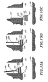
- FIGS 15A through 15C illustrate the use of the embodiment of the present invention just described with reference to Figure 14.
- the leveling portion 422 does not contact the sidewall 430A of the workpiece 430 during advancement because the diameter of the second protective ring 424 is slightly larger than the diameter of the leveling portion 422.
- the diameter of the first protective ring 420 is approximately the same size or slightly larger than the diameter of the leveling portion 422. Therefore, as illustrated in Figure 15B, the leveling portion 422 provides a means for removing unwanted projections from the sidewall 430A in the region mear the corner 430B as the second protective ring 424 is advanced beyond the corner 430B.
- the abrasive mechanism 418 may then be used to round off or polish the corner 430B, as illustrated in Figure 15C
- FIGs 16A and 16B illustrate the distal end portion 500 of a burr removal apparatus in accordance with another preferred embodiment of the present invention.
- a rotatable shaft 502 has at one end thereof a first abrasive mechanism 518, a collar 520 and a second abrasive mechanism 522, extending laterally as a plate of finite thickness or as a collection of abrasive projections.
- the distal end portion 500 of the burr removal apparatus is advanced through the workpiece 530, as shown in Figure 16A, such that the collar 520 rides along the wall 530A.
- the tool When the first abrasive mechanism 518 has removed the burrs from the corner 530B of the workpiece 530, the tool is advanced into a second position, as shown in Figure 16B. In this position, the second abrasive mechanism 522 provides abrasive action along the side wall 530A and comer 530B of the workpiece 530.
- the abrasive ring may also be positioned to extend onto surface 530C if desired.
- the first and second abrasive mechanisms, 518 and 522 are preferably of different abrasive materials (e.g., for rough deburring and for edge finishing, respectively). Therefore, at least two different deburring tasks can be performed without changing an abrasive mechanism or removing the distal end portion 500 of the burr removal apparatus from the workpiece 530.
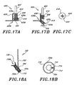
- FIGs 17A and 17B illustrate the distal end portion 600 of a burr removal apparatus in accordance with another preferred embodiment of the present invention.
- the abrasive mechanism 618 which extends laterally from a rotatable working shaft 602, can be rotated to an arbitrary angle relative to the shaft 602. This feature advantageously allows the abrasive mechanism 618 to be tilted relative to the working shaft 602, as shown in Figure 17B, while the working shaft 602 and abrasive mechanism 618 are rotated.
- the cross-sectional shape of the abrasive mechanism 618 is preferably concave and has at least one linear segment (or is polygonal), with geometric parameters that enable the abrasive mechanism 618 to remove burrs on a sharply angled polygonal corner 630B (e.g., a right angle corner), as illustrated in Figure 17B.
- the surface of the abrasive mechanism 618 can be a relatively hard abrasive for rough deburring or can be a relatively soft abrasive for surface finishing.
- the device includes one, two or more non-abrasive collars, 620A and 620B, to protect the side wall 630A as the abrasive mechanism 618 is moved into position or is removed from the workpiece 630, as illustrated in Figure 17A.
- Figure 17C is a top view of the abrasive mechanism 618 illustrating one embodiment in which the working shaft 602 is coupled to the abrasive mechanism 618 such that the abrasive mechanism 618 may pivot relative to the working shaft 602.
- the working shaft 602 has an X-shaped cross-section that fits through a similarly shaped hole 604 extending through the abrasive mechanism 618.
- the hole 604 is larger than the working shaft 602 and therefore the abrasive mechanism 618 may pivot, within a limited range, about the shaft 602.
- a bottom plate 606 is attached to the distal end of the working shaft 602 that prevents the abrasive mechanism 618 from sliding off the working shaft 602.
- a coiled spring 608 is fitted over the shaft. The top end of the spring 608 is maintained on the shaft 602 by a top plate 610. The bottom end of the spring 608 engages the top of the abrasive mechanism 618 thereby pushing the abrasive mechanism 618 against the bottom plate 606.
- the abrasive mechanism 618 also rotates to abrade a surface.
- the abrasive mechanism 618 is able to tilt such that it can maintain constant engagement with the corner 630B of the workpiece 630 at all times.
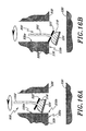
- Figures 18A and 18B illustrate the distal end portion 700 of a burr removal apparatus in accordance with another preferred embodiment of the present invention.
- a spherically shaped ball 704 is fixedly attached to the distal end of the working shaft 702 and an abrasive mechanism 718 is movably coupled to the ball 704.
- the abrasive mechanism 718 is formed as a disc-shaped member located between first and second protective collars, 720A and 720B.
- a hole 710 extends through the abrasive mechanism 718 and collars 720A, 720B. The hole 710 is shaped to conform to the surface of the ball 704.
- the middle of the ball 704 (wherein the diameter is largest) is located within the center of the abrasive mechanism 718 and therefore the ball 704 is locked within the abrasive mechanism 718.
- the abrasive mechanism 718 is free to pivot or tilt relative to the ball 704 such that the central axis of the abrasive mechanism 718 is different than the axis of the working shaft 702 as illustrated in Figure 18A.
- the exterior of the ball is provided with a key 712 that fits into a slot 714 formed along the hole 710 in the abrasive mechanism 718, as illustrated in Figure 18B.
- the abrasive mechanism 718 rotates with the working shaft 702 and, at the same time, the edge of the abrasive mechanism 718 is free to tilt up and down. Therefore, edge of the abrasive mechanism is able to maintain constant contact with the corner 730B of the workpiece 730 as the working shaft 702 is rotated, as illustrated in Figure 18A.
- the cross-sectional shape of the abrasive mechanism 718 is curvilinear and concave, to more easily abrade a rounded corner 730B on a workpiece 730.
- Figure 19 illustrates another embodiment of the present invention wherein the working shaft 802 can be steered to help navigate an abrasive mechanism 818 into a difficult area within a workpiece.
- the working shaft 802 includes a superelastic core 804 that easily bends into an arc.
- the shaft 802 also includes: a partly flexible shaft guide sleeve 806 that covers most of, and may but need not rotate with, the shaft core 804; and an inflexible guide sleeve 808 that covers part of the shaft guide sleeve 806 and does not rotate.
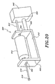
- FIG 20 illustrates an anti-vibration mechanism 900 that can be advantageously used with any of the previously described embodiments of the present invention.
- the anti-vibration mechanism 900 provides a means for improving the surface finish of a workpiece by reducing undesirable vibration and restricting movement of the working shaft 916.
- the shaft restrictor 900 is adapted to restrict undesirable lateral motion of a working shaft 916 as the shaft 916 turns and the abrasive mechanism 918 encounters mechanical resistance.
- the drive shaft 912 extends through a first aperture 904 on a back wall 930 of the bracket 910.
- the back wall 930 is connected or rigidly attached to a shaft driver mechanism 940 (e.g., a motor), or to some other relatively rigid device, by a second plate or anchor 934.
- a shaft driver mechanism 940 e.g., a motor
- the diameter of the first aperture 904 is slightly larger than the diameter of the drive shaft 912 and may include a bushing to minimize any frictional force produced by the rotation of the drive shaft 912.
- the front wall 932 of the bracket 910 includes an aperture 906 that permits motion of a shaft 916 in one lateral direction (x) but prevents motion of the shaft in a second lateral direction (y).
- This embodiment of a shaft restrictor will be particularly useful where the abrasive mechanism 918 and shaft 916 must move in one lateral direction to follow the contours of the workpiece to be deburred.
- the flexible coupling member 914 allows the drive shaft 912 to deflect relative to the working shaft 916.
- the aperture in the front wall may be a circular hole that restricts all lateral motion of the working shaft 916.
- the presence of the two aligned apertures at spaced apart locations ensures that the drive shaft 912 and the working shaft 916 are aligned and move at most a minimal lateral distance as they rotate.
- the preferred shape of the abrasive mechanism will depend largely on the shape of the surface to be deburred. Various desirable cross-sections may include ovular, quadrilateral, trapezoidal or polygonal.
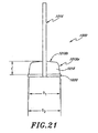
- Figure 21 illustrates the distal end portion 1000 of a burr removal tool having an abrasive mechanism 1018 with one preferred shape. The illustrated shape is particularly well-suited for removing burrs and other unwanted material from a corner location in a workpiece.
- the angular difference between the side 1018A and the top 1018B of the abrasive mechanism 1018 provides the user with excellent control over the lateral and longitudinal movement of the device as it moves around the corner of a workpiece.
- the top 1018B of the abrasive mechanism 1018 is nearly perpendicular to the working shaft 1016. This feature allows the device to extend deeply around a corner to ensure that the burr removal is complete.
- the length L of the abrasive mechanism 1018 can be varied according to the desired use and the size of the space in which the device is utilized.
- a significant feature of the present invention is the inclusion of a protective collar 1020 having a diameter D 2 larger than the diameter D 1 of the abrasive mechanism 1018. This feature ensures that the abrasive mechanism 1018 does not inadvertently damage the part as the tool is advanced toward the location to be deburred. It will be appreciated that the difference in diameters between D 1 and D 2 affects the amount of material contacted by the abrasive mechanism 1018 when the device is used to deburr an edge at the intersection of two through holes.
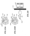
- Figures 22A and 22B are end views illustrating an arrangement that incorporates some of the invention's features in a milling machine or lathe, for example, as a retrofit arrangement.
- Figure 22A illustrates a rotatable base 1102 having a longitudinal central axis 1103 and having one or more apertures 1104-j formed in a rotatable base 1102.
- One or more of the apertures has a subsidiary rotation mechanism 1105-j positioned therein that provides independent rotation of a working shaft 1106-j having a working tip (e.g. an abrasive mechanism).
- the subsidiary rotation mechanism 1105-j can serve as a shaft drive mechanism for a burr removal system (similar to the shaft drive mechanism shown as 21 in Figures 1A and 1B).
- the rotatable base 1102 can rotate about its axis 1103 in a clockwise direction, and the subsidiary rotation mechanism 1105-j can independently rotate the shaft 1106-j in a clockwise or counterclockwise direction, as illustrated by the arrows in Figure 22A.
- This feature provides a "turret" mechanism which allows a wide variety of burr removal and edge finishing tools to be simultaneously incorporated into a single mechanism. Rotation of the turret allows the user to select and interchange tools in a quick and easy manner.
- each of the apertures may be provided without a shaft drive mechanism, as illustrated in Figure 22B.
- rotation of the shaft 1106-j may be provided by an external source, such as, for example, a pneumatic pump or an electrical motor that provides power to each of the working shafts.
- Figure 23 is a side view illustrating a subsidiary rotation mechanism 1105 that may be located within an aperture of the rotatable base 1102 shown in Figure 22A.
- the subsidiary rotation mechanism 1105 is connected to an abrasive mechanism 1107 and associated collar 1108 through a rotatable working shaft 1106.
- the shaft 1106 is capable of moving longitudinally, to position the abrasive mechanism 1107 relative to a workpiece (not shown).
- the shaft 1106 further comprises a flywheel 1110 (or other similar rotatable mass) that provides a rotational inertia storage mechanism.
- the subsidiary rotation mechanism 1105 is activated to increase the rotational speed of the shaft 1106.
- the shaft 1106 Once the shaft 1106 has reached an appropriate angular velocity, the shaft is moved longitudinally along the axis of the shaft 1106 until the abrasive mechanism 1107 engages a portion of the work surface to be deburred.
- the subsidiary rotation mechanism 1105 may continue in its activated state to rotate the shaft 1106 and the abrasive mechanism 1107.
- the subsidiary rotation mechanism 1105 can be deactivated or turned off.
- the shaft 1106, the abrasive mechanism 1107 and the associated collar 1108 will continue to rotate at an angular velocity that slowly decreases due to internal friction and due to friction encountered by the abrasive mechanism 1107 as one or more burrs are removed.
- Inclusion of the rotatable mass 1110 on the shaft 1106 provides additional rotational inertia (I ⁇ w 2 , where I is the moment of inertia of the rotatable mass alone) that helps to sustain the angular velocity in the presence of friction.
- the rotatable mass 1110 allows the burr removal tool to be used for a substantial period of time in the absence of a power source.
- the abrasive material used in an abrasive mechanism may include one or more materials, such as, for example, high-carbon steel, metal impregnated with alumina or boron nitride or boron carbide or diamond fragments, titanium, tungsten, a wire bristles, plastic bristles impregnated with an abrasive material, a polishing stone or any other suitable burr removal material having a Mohs hardness substantially greater than that of most metals (i.e., at least equal to about 5.5).
- the abrasive mechanism is preferably made of tungsten carbide.
- the non-abrasive material used in a protective collar may be a plastic or other sacrificial material or may be a material with a Mohs hardness index that is below but near that of the metal from which burrs are to be removed. Many metals have Mohs hardness indices of around 5.5 so that a non-abrasive material with a Mohs hardness index in the range 3-5 may be suitable.
- Non-abrasive materials which may be used with the protective collar include, wood, plastic, rubber, polished metal or any other material with a Mohs hardness less than 5.5.
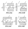
- Figures 24A through 24D are cross-sectional views of the interior of a metallic workpiece illustrating an exemplary use of the invention for removing burrs at a location where two apertures intersect to form a "T-shaped" hole.
- the breakthrough of the drill hole for the second aperture 2 into the first aperture 4 will produce an ellipsoid shaped edge that may include metal burrs 6.
- the burrs 6 located along this ellipsoid are typically very difficult to remove due to their locations within the workpiece.
- conventional burr removal tools are not well-suited for this purpose because the ellipsoid edge is non-planar due to the geometry of intersecting holes.
- the burr removal tool of the present invention is well-suited for removing burrs from such a workpiece. The operation of the burr removal tool will be described with reference to the embodiment of the present invention described in Figures 1A and 1B.
- the rotating tool 10 is being advanced longitudinally through an aperture in a workpiece as the workpiece 8 is being rotated about the central axis A-A of the aperture.
- the tool 10 is advanced along a path that is parallel to the axis of rotation of the workpiece 8. During the initial advancement into the workpiece 8, the tool 10 moves through the aperture 4 without touching the wall of the aperture.
- the tool is then advanced further through the aperture along a path that is eccentric from the axis of rotation of the workpiece.
- the collar 20 advances beyond a corner C of the workpiece, the collar 20 drops down and the angle between the working shaft 16 and the adjacent surface of the workpiece is reduced.
- this angle fluctuates as the workpiece 8 is rotated because the collar 20 will come in and out of contact with the side wall of the second aperture 2.
- Figure 24C illustrates the workpiece 8 with the second aperture 2 in a position that is perpendicular to the illustrated view. In this position, the collar 20 contacts the side wall of the aperture.
- Figure 24D illustrates the workpiece 8 with the second aperture 2 rotated another 90 degrees.
- the abrasive mechanism comes into contact with the corner C where the first aperture 4 meets the second aperture 2. Therefore, as can be seen by this sequence of figures, the thickness of the collar will have direct affect on the amount of time that the abrasive mechanism 18 contacts the corner C of the aperture during a rotational cycle. Therefore, the amount of material removed from the workpiece can be controlled by adjusting the diameter of the collar relative to the diameter of the abrasive mechanism.
- Each embodiment of the invention incorporates one or more of the following features: (1) provision of a non-abrasive collar, combined with an adjacent abrasive mechanism, to protect a surface from unintended abrasion when the system is being moved into position to remove one or more burrs; (2) provision of an abrasive mechanism having a cross-sectional shape that corresponds to the local shape of the surface from which one or more burrs is to be removed; (3) provision of a shaft that can be mechanically loaded or deflected to provide an abrasive mechanism with a directed force against a surface from which one or more burrs is to be removed; (4) provision of a shaft restrictor that restricts shaft motion in one or more lateral directions when the abrasive mechanism is rotating; and (5) use of rotational inertia storage to sustain rotation of the shaft(s), abrasive mechanism(s) and collar(s) after the shaft drive mechanism is turned off and the angular velocity decreases slowly due to frictional forces.
Landscapes
- Engineering & Computer Science (AREA)
- Mechanical Engineering (AREA)
- General Engineering & Computer Science (AREA)
- Physics & Mathematics (AREA)
- Acoustics & Sound (AREA)
- Aviation & Aerospace Engineering (AREA)
- Polishing Bodies And Polishing Tools (AREA)
- Grinding And Polishing Of Tertiary Curved Surfaces And Surfaces With Complex Shapes (AREA)
- Control And Other Processes For Unpacking Of Materials (AREA)
- Preliminary Treatment Of Fibers (AREA)
- Encapsulation Of And Coatings For Semiconductor Or Solid State Devices (AREA)
Abstract
Description
Claims (19)
- A burr removal apparatus, comprising:characterised in that said first cross-sectional profile is substantially greater than said access device and said abrasive mechanism is shaped for effecting burr removal from a comer of said workpiece.an access device (16) having proximal and distal end portions, said access device being rotatable about a longitudinal axis;at least one abrasive mechanism (18) disposed along said distal end portion of said access device, said abrasive mechanism having a first cross-sectional profile, said abrasive mechanism being formed with an abrasive material for abrading a selected section of a workpiece; andat least one non-abrasive member (20) for protecting said workpiece against undesirable abrasion, said non-abrasive member having a second cross sectional profile substantially greater than said abrasive mechanism, said non-abrasive member being positioned to protect said workpiece as said abrasive mechanism is advanced along said workpiece;
- The apparatus oi claim 1, wherein said non-abrasive member is mounted on said abrasive mechanism.
- The apparatus of claim 1, wherein said non-abrasive member is mounted on said access device.
- The apparatus of claim 1, wherein said non-abrasive member is mounted distal to said abrasive mechanism.
- The apparatus of claim 1, wherein said non-abrasive member has a cross-section with a circular shape.
- The apparatus of claim 1, wherein said abrasive mechanism is relatively small in relation to a perimeter of a surface to be de-burred.
- The apparatus of claim 1, wherein said non-abrasive member is a collar.
- The apparatus of claim 7, wherein said collar extends around an exterior portion of said abrasive mechanism.
- The apparatus of claim 7, wherein said abrasive mechanism is formed with a substantially hemi-spherical shape and said collar extends around an exterior portion of said abrasive mechanism.
- The apparatus of claim 7, wherein said abrasive mechanism is formed with a substantially spherical shape and said collar extends around an exterior central portion of said abrasive mechanism.
- The apparatus of claim 1, wherein said access device can deflect or bend in a selected direction in response to a force exerted on said shaft in said selected direction.
- The apparatus of claim 11, further comprising a coiled spring for coupling said distal end of said access device to said abrasive mechanism, said coiled spring being adapted to allow said abrasive mechanism to deflect relative to said access device.
- The apparatus of claim 1, further comprising an abrasive ring coupled to said access device at a location proximal to said abrasive mechanism.
- The apparatus of claim 1, wherein said abrasive mechanism is pivotally coupled to said distal end portion of said access device.
- The apparatus of claim 1, wherein said access device is an elongate working shaft having a non-abrasive surface.
- The burr removal apparatus of Claim 15, further composing:a substantially rigid drive shaft having proximal and distal end portions; anda flexible coupling member located between said distal end portion of said drive shaft and said proximal end of said working shaft for allowing said working shaft to deflect relative to said drive shaft.
- The burr removal apparatus of Claim 1, wherein said abrasive mechanism is shaped for abrading a corner of a workpiece.
- The burr removal apparatus of Claim 1, wherein said non-abrasive mechanism is adapted to engage a wall of said workpiece during said advancement along said workpiece.
- A method for removing a burr from an edge of a workpiece, comprising:characterised in that said abrasive mechanism has a diameter greater than said access device and wherein said burr removal apparatus is advanced along a wall of said workpiece wherein said non-abrasive member engages said wall until said non-abrasive member is advanced distally of said edge of said workpiece such that said abrasive mechanism contacts said edge; and at least one burr is removed by abrading said edge through contact with said abrasive mechanism.providing an elongate access device having a distal end portion;providing an abrasive mechanism along said distal end portion of said access device, said abrasive mechanism including an abrasive material that can abrade said edge of said workpiece,providing a non-abrasive member along said distal end portion of said access device that will not substantially abrade said workpiece, said non-abrasive member having a diameter greater than said abrasive mechanism; androtating said access device relative to said workpiece;
Applications Claiming Priority (3)
| Application Number | Priority Date | Filing Date | Title |
|---|---|---|---|
| US21482900P | 2000-06-28 | 2000-06-28 | |
| US214829P | 2000-06-28 | ||
| PCT/US2001/020803 WO2002000391A1 (en) | 2000-06-28 | 2001-06-28 | Burr removal apparatus |
Publications (2)
| Publication Number | Publication Date |
|---|---|
| EP1294532A1 EP1294532A1 (en) | 2003-03-26 |
| EP1294532B1 true EP1294532B1 (en) | 2004-12-22 |
Family
ID=22800567
Family Applications (1)
| Application Number | Title | Priority Date | Filing Date |
|---|---|---|---|
| EP01950695A Expired - Lifetime EP1294532B1 (en) | 2000-06-28 | 2001-06-28 | Burr removal apparatus |
Country Status (9)
| Country | Link |
|---|---|
| US (6) | US6846226B2 (en) |
| EP (1) | EP1294532B1 (en) |
| JP (2) | JP5001502B2 (en) |
| KR (1) | KR100913442B1 (en) |
| AT (1) | ATE285313T1 (en) |
| AU (1) | AU2001271663A1 (en) |
| CA (1) | CA2413375C (en) |
| DE (1) | DE60107948T2 (en) |
| WO (1) | WO2002000391A1 (en) |
Families Citing this family (26)
| Publication number | Priority date | Publication date | Assignee | Title |
|---|---|---|---|---|
| US6846226B2 (en) * | 2000-06-28 | 2005-01-25 | Michael Kapgan | Burr removal apparatus |
| EP1362659B1 (en) | 2002-05-17 | 2011-03-23 | Gühring, Jörg, Dr. | Tool, device and method for deburring bores |
| KR20040023043A (en) * | 2002-09-10 | 2004-03-18 | 현대자동차주식회사 | Burr cutting device for inside curved surface |
| SE526691C2 (en) * | 2003-03-18 | 2005-10-25 | Pergo Europ Ab | Panel joint with friction raising means at longitudinal side joint |
| DE102004010372A1 (en) | 2004-03-03 | 2005-09-22 | Gühring, Jörg, Dr. | Tool for deburring holes |
| US20090061746A1 (en) * | 2007-09-04 | 2009-03-05 | Baker Hughes Incorporated | Burr Removing Apparatus and Method |
| JP5150194B2 (en) * | 2007-10-15 | 2013-02-20 | 株式会社ジーベックテクノロジー | Polishing tool and processing method |
| FR2952844B1 (en) * | 2009-11-24 | 2012-02-03 | Peugeot Citroen Automobiles Sa | DEBURRING A WORKPIECE |
| WO2011071306A2 (en) * | 2009-12-08 | 2011-06-16 | 군산대학교산학협력단 | Apparatus for deburring an object |
| US10245045B2 (en) * | 2010-06-30 | 2019-04-02 | Smith & Nephew, Inc. | Resection instrument |
| US10206690B2 (en) * | 2010-06-30 | 2019-02-19 | Smith & Nephew, Inc. | Bone and tissue marker |
| FR2968587B1 (en) * | 2010-12-10 | 2014-04-11 | Snecma | ABRASIVE BRUSH WITH CONCAVE SIDE SURFACE |
| JP5780173B2 (en) * | 2012-02-13 | 2015-09-16 | 株式会社デンソー | Grinding apparatus and grinding method using the same |
| DE102012006410B4 (en) * | 2012-03-30 | 2013-11-28 | Heraeus Quarzglas Gmbh & Co. Kg | Process for producing a quartz glass hollow cylinder |
| US9446455B2 (en) * | 2014-05-29 | 2016-09-20 | Sanexen Environmental Services Inc. | Drilling apparatus |
| AU2015302209B2 (en) | 2014-08-11 | 2020-05-07 | Smith & Nephew, Inc. | A medical device for repairing soft tissue and method of using same |
| CN208977624U (en) * | 2016-05-26 | 2019-06-14 | 三菱电机株式会社 | Burr removal tool |
| WO2019138471A1 (en) * | 2018-01-10 | 2019-07-18 | 株式会社ジーベックテクノロジー | Polishing brush holder and polishing device |
| JP7096146B2 (en) * | 2018-12-21 | 2022-07-05 | 日立グローバルライフソリューションズ株式会社 | Deburring device for stator and deburring control method for stator |
| CN110193543B (en) * | 2019-06-28 | 2024-06-21 | 佛山职业技术学院 | Automatic feeding system of metal round tube |
| CN111660109B (en) * | 2020-06-23 | 2021-10-01 | 泰州鸿材科技有限公司 | A plate drilling self-polishing integrated device |
| JP7750504B2 (en) * | 2021-10-06 | 2025-10-07 | 株式会社タブチ | Pipe cutting method, pipe cutting device |
| JP7107512B1 (en) * | 2021-11-17 | 2022-07-27 | 株式会社ジーベックテクノロジー | Grinding wheels with shafts and abrasive tools |
| CN116252147B (en) * | 2023-04-27 | 2023-07-25 | 无锡市汇灵机械有限公司 | Automatic machining and assembling mechanism for guide seat |
| JP7612790B1 (en) | 2023-09-01 | 2025-01-14 | 三菱重工業株式会社 | Processing tools and processing methods |
| JP7799869B1 (en) * | 2025-01-24 | 2026-01-15 | マーレエンジンコンポーネンツジャパン株式会社 | Deburring tool, deburring device, grinding tool and grinding device |
Family Cites Families (33)
| Publication number | Priority date | Publication date | Assignee | Title |
|---|---|---|---|---|
| US2514394A (en) | 1945-01-09 | 1950-07-11 | Frank J Irving | Coupling |
| US2942092A (en) * | 1959-02-27 | 1960-06-21 | Fred W Cammann | Internal tube cutter |
| US3871139A (en) | 1974-05-10 | 1975-03-18 | Rands Steve Albert | Multiple-compliant-bristle, self-centering self-sizing rotary abrasive hone |
| JPS5253594A (en) * | 1975-10-27 | 1977-04-30 | Seiko Seiki Co Ltd | Method of controlling grinding operation for internal grinding machine |
| US4136487A (en) * | 1977-11-21 | 1979-01-30 | Khokhulin Vladimir N | Arrangement for abrasive machining of shaped surfaces |
| US4286416A (en) * | 1978-08-01 | 1981-09-01 | Westinghouse Electric Corp. | Segmented flexible hone |
| JPS55120451U (en) * | 1979-02-16 | 1980-08-26 | ||
| US4343577A (en) | 1980-07-14 | 1982-08-10 | Purdon Jerome R | Deburring tool |
| JPS615505U (en) | 1984-06-16 | 1986-01-14 | 株式会社 妙徳 | Burr cutting equipment |
| US4601223A (en) * | 1984-07-16 | 1986-07-22 | Westinghouse Electric Corp. | Flail tube cutter |
| DE3644441A1 (en) * | 1986-12-24 | 1988-07-07 | Bosch Gmbh Robert | TENSIONING DEVICE FOR DETACHABLE FASTENING OF A TOOL, IN PARTICULAR A DISC |
| JP2599972B2 (en) * | 1988-08-05 | 1997-04-16 | 株式会社 チップトン | Deburring method |
| US5177904A (en) * | 1988-10-15 | 1993-01-12 | Nagel Maschinen-Und Werkzeugfabrik Gmbh | Method for honing workpieces |
| JPH02237756A (en) * | 1989-03-09 | 1990-09-20 | Toshiba Corp | Deburring tool |
| US5384983A (en) * | 1990-02-16 | 1995-01-31 | Ab Uva | Method and grinding machine for the internal grinding of bores |
| JPH03256659A (en) * | 1990-03-05 | 1991-11-15 | Suzuki Motor Corp | Chamfering method for cylinder port for two-cycle engine |
| JPH0541660U (en) * | 1991-11-15 | 1993-06-08 | 新キヤタピラー三菱株式会社 | Automatic centripetal cutting machine |
| JP3288745B2 (en) * | 1992-03-17 | 2002-06-04 | 臼井国際産業株式会社 | Deburring device |
| US5482498A (en) * | 1992-04-02 | 1996-01-09 | Toyo Co., Ltd. | Honing tool and super precision finishing method using the same |
| JP3241799B2 (en) | 1992-04-27 | 2001-12-25 | 日本ユニット株式会社 | Polishing tool |
| US5321918A (en) * | 1992-12-14 | 1994-06-21 | Brian Frank J | Spindle grinding method and apparatus |
| JPH0711258U (en) * | 1993-07-30 | 1995-02-21 | 日機装株式会社 | Grinding machine |
| JPH08192344A (en) | 1995-01-13 | 1996-07-30 | Mitsubishi Electric Corp | Cylinder inner surface finishing device and cylinder inner surface finishing method |
| US5795217A (en) | 1995-11-22 | 1998-08-18 | International Business Machines Corporation | Stressed burnisher |
| US5681209A (en) * | 1996-01-29 | 1997-10-28 | Constant Velocity Systems, Inc. | Housing grinding machine |
| US5895311A (en) * | 1996-06-06 | 1999-04-20 | Fuji Xerox Co., Ltd. | Abrasive device that maintains normal line of contact with curved abrasive surface and method of using same |
| JP2845823B2 (en) * | 1996-07-19 | 1999-01-13 | 株式会社湘南合成樹脂製作所 | cutter |
| JPH10180541A (en) * | 1996-12-19 | 1998-07-07 | Kayaba Ind Co Ltd | Deburring tool |
| DE19904944A1 (en) | 1999-02-06 | 2000-04-20 | Bosch Gmbh Robert | Oscillated and twisted de-burring tool, for rounding and polishing hole edges, includes spreading head and highly stressed inner edge of fuel injection nozzle |
| JP3632489B2 (en) * | 1999-03-02 | 2005-03-23 | 日本精工株式会社 | Internal grinding method and internal grinding machine |
| US6857943B2 (en) * | 2000-06-28 | 2005-02-22 | Michael Kapgan | Burr removal apparatus |
| US6846226B2 (en) * | 2000-06-28 | 2005-01-25 | Michael Kapgan | Burr removal apparatus |
| US6569177B1 (en) * | 2001-01-19 | 2003-05-27 | Scimed Life Systems, Inc. | Ablation atherectomy burr |
-
2001
- 2001-05-07 US US09/850,908 patent/US6846226B2/en not_active Expired - Lifetime
- 2001-06-28 AT AT01950695T patent/ATE285313T1/en not_active IP Right Cessation
- 2001-06-28 CA CA2413375A patent/CA2413375C/en not_active Expired - Lifetime
- 2001-06-28 WO PCT/US2001/020803 patent/WO2002000391A1/en not_active Ceased
- 2001-06-28 DE DE60107948T patent/DE60107948T2/en not_active Expired - Lifetime
- 2001-06-28 EP EP01950695A patent/EP1294532B1/en not_active Expired - Lifetime
- 2001-06-28 KR KR1020027017894A patent/KR100913442B1/en not_active Expired - Lifetime
- 2001-06-28 AU AU2001271663A patent/AU2001271663A1/en not_active Abandoned
- 2001-06-28 JP JP2002505160A patent/JP5001502B2/en not_active Expired - Lifetime
-
2004
- 2004-12-28 US US11/023,976 patent/US7097543B2/en not_active Expired - Lifetime
-
2006
- 2006-08-29 US US11/512,722 patent/US20070141966A1/en not_active Abandoned
-
2011
- 2011-03-29 US US13/075,100 patent/US8512101B2/en not_active Expired - Fee Related
-
2012
- 2012-04-09 JP JP2012088398A patent/JP5380570B2/en not_active Expired - Lifetime
-
2013
- 2013-07-09 US US13/937,933 patent/US20130309947A1/en not_active Abandoned
-
2014
- 2014-06-25 US US14/315,183 patent/US20140308881A1/en not_active Abandoned
Also Published As
| Publication number | Publication date |
|---|---|
| JP5380570B2 (en) | 2014-01-08 |
| EP1294532A1 (en) | 2003-03-26 |
| US20130309947A1 (en) | 2013-11-21 |
| DE60107948D1 (en) | 2005-01-27 |
| KR20030028491A (en) | 2003-04-08 |
| JP2012131029A (en) | 2012-07-12 |
| US20060084368A1 (en) | 2006-04-20 |
| US20020013988A1 (en) | 2002-02-07 |
| AU2001271663A1 (en) | 2002-01-08 |
| US20140308881A1 (en) | 2014-10-16 |
| US6846226B2 (en) | 2005-01-25 |
| JP2004501782A (en) | 2004-01-22 |
| DE60107948T2 (en) | 2005-12-08 |
| CA2413375A1 (en) | 2002-01-03 |
| US8512101B2 (en) | 2013-08-20 |
| ATE285313T1 (en) | 2005-01-15 |
| WO2002000391A9 (en) | 2003-02-06 |
| CA2413375C (en) | 2010-05-11 |
| JP5001502B2 (en) | 2012-08-15 |
| US20070141966A1 (en) | 2007-06-21 |
| WO2002000391A1 (en) | 2002-01-03 |
| US7097543B2 (en) | 2006-08-29 |
| US20110244765A1 (en) | 2011-10-06 |
| KR100913442B1 (en) | 2009-08-21 |
Similar Documents
| Publication | Publication Date | Title |
|---|---|---|
| CA2413375C (en) | Burr removal apparatus | |
| US6857943B2 (en) | Burr removal apparatus | |
| JP3868474B1 (en) | Machining tools | |
| JPWO2004009293A1 (en) | Brush-shaped grinding wheel manufacturing method, brush-shaped grinding wheel, and brush for polishing machine | |
| JP4665440B2 (en) | Machining tools | |
| JP2002536195A (en) | Grinding tools and grinding cups and grinding spindles for grinding buttons of rock drill bits, and methods of mounting grinding cups on grinding spindles | |
| JPH11179720A (en) | Core bit with fall prevention core lifter | |
| KR102927062B1 (en) | Polishing Brushes and Polishing Methods | |
| JP2008284677A (en) | Machining tools | |
| JP6991631B1 (en) | Polishing equipment | |
| KR102350096B1 (en) | Drill guide bush | |
| US6781797B2 (en) | Lubricated thread screw drive and method of manufacturing same | |
| JP4481848B2 (en) | Swing drive type tool | |
| KR102918096B1 (en) | Drill cutting tool grinding device | |
| JP2000263407A (en) | Method and apparatus for grinding outer peripheral spherical portion and grinding wheel | |
| US12151506B2 (en) | Reciprocal vibration type electric engraving pen | |
| JPH0733549U (en) | Pipe material polishing equipment | |
| JP4831453B2 (en) | Forming tools | |
| JPH07251359A (en) | Inner surface finishing device for curved pipe | |
| JP2013137086A (en) | Nut for ball screw | |
| JP2003136324A (en) | Anti-chatter device for rotating tools | |
| KR20120092860A (en) | Machine tool having screw holder |
Legal Events
| Date | Code | Title | Description |
|---|---|---|---|
| PUAI | Public reference made under article 153(3) epc to a published international application that has entered the european phase |
Free format text: ORIGINAL CODE: 0009012 |
|
| 17P | Request for examination filed |
Effective date: 20030116 |
|
| AK | Designated contracting states |
Kind code of ref document: A1 Designated state(s): AT BE CH CY DE DK ES FI FR GB GR IE IT LI LU MC NL PT SE TR |
|
| AX | Request for extension of the european patent |
Extension state: AL LT LV MK RO SI |
|
| GRAP | Despatch of communication of intention to grant a patent |
Free format text: ORIGINAL CODE: EPIDOSNIGR1 |
|
| GRAS | Grant fee paid |
Free format text: ORIGINAL CODE: EPIDOSNIGR3 |
|
| GRAA | (expected) grant |
Free format text: ORIGINAL CODE: 0009210 |
|
| AK | Designated contracting states |
Kind code of ref document: B1 Designated state(s): AT BE CH CY DE DK ES FI FR GB GR IE IT LI LU MC NL PT SE TR |
|
| PG25 | Lapsed in a contracting state [announced via postgrant information from national office to epo] |
Ref country code: FI Free format text: LAPSE BECAUSE OF FAILURE TO SUBMIT A TRANSLATION OF THE DESCRIPTION OR TO PAY THE FEE WITHIN THE PRESCRIBED TIME-LIMIT Effective date: 20041222 Ref country code: NL Free format text: LAPSE BECAUSE OF FAILURE TO SUBMIT A TRANSLATION OF THE DESCRIPTION OR TO PAY THE FEE WITHIN THE PRESCRIBED TIME-LIMIT Effective date: 20041222 Ref country code: BE Free format text: LAPSE BECAUSE OF FAILURE TO SUBMIT A TRANSLATION OF THE DESCRIPTION OR TO PAY THE FEE WITHIN THE PRESCRIBED TIME-LIMIT Effective date: 20041222 Ref country code: TR Free format text: LAPSE BECAUSE OF FAILURE TO SUBMIT A TRANSLATION OF THE DESCRIPTION OR TO PAY THE FEE WITHIN THE PRESCRIBED TIME-LIMIT Effective date: 20041222 Ref country code: AT Free format text: LAPSE BECAUSE OF FAILURE TO SUBMIT A TRANSLATION OF THE DESCRIPTION OR TO PAY THE FEE WITHIN THE PRESCRIBED TIME-LIMIT Effective date: 20041222 |
|
| REG | Reference to a national code |
Ref country code: GB Ref legal event code: FG4D |
|
| REG | Reference to a national code |
Ref country code: CH Ref legal event code: EP |
|
| REG | Reference to a national code |
Ref country code: IE Ref legal event code: FG4D |
|
| REF | Corresponds to: |
Ref document number: 60107948 Country of ref document: DE Date of ref document: 20050127 Kind code of ref document: P |
|
| PG25 | Lapsed in a contracting state [announced via postgrant information from national office to epo] |
Ref country code: SE Free format text: LAPSE BECAUSE OF FAILURE TO SUBMIT A TRANSLATION OF THE DESCRIPTION OR TO PAY THE FEE WITHIN THE PRESCRIBED TIME-LIMIT Effective date: 20050322 Ref country code: DK Free format text: LAPSE BECAUSE OF FAILURE TO SUBMIT A TRANSLATION OF THE DESCRIPTION OR TO PAY THE FEE WITHIN THE PRESCRIBED TIME-LIMIT Effective date: 20050322 Ref country code: GR Free format text: LAPSE BECAUSE OF FAILURE TO SUBMIT A TRANSLATION OF THE DESCRIPTION OR TO PAY THE FEE WITHIN THE PRESCRIBED TIME-LIMIT Effective date: 20050322 |
|
| PG25 | Lapsed in a contracting state [announced via postgrant information from national office to epo] |
Ref country code: ES Free format text: LAPSE BECAUSE OF FAILURE TO SUBMIT A TRANSLATION OF THE DESCRIPTION OR TO PAY THE FEE WITHIN THE PRESCRIBED TIME-LIMIT Effective date: 20050402 |
|
| REG | Reference to a national code |
Ref country code: CH Ref legal event code: NV Representative=s name: ISLER & PEDRAZZINI AG |
|
| NLV1 | Nl: lapsed or annulled due to failure to fulfill the requirements of art. 29p and 29m of the patents act | ||
| PG25 | Lapsed in a contracting state [announced via postgrant information from national office to epo] |
Ref country code: CY Free format text: LAPSE BECAUSE OF FAILURE TO SUBMIT A TRANSLATION OF THE DESCRIPTION OR TO PAY THE FEE WITHIN THE PRESCRIBED TIME-LIMIT Effective date: 20050628 Ref country code: IE Free format text: LAPSE BECAUSE OF NON-PAYMENT OF DUE FEES Effective date: 20050628 Ref country code: LU Free format text: LAPSE BECAUSE OF NON-PAYMENT OF DUE FEES Effective date: 20050628 |
|
| PG25 | Lapsed in a contracting state [announced via postgrant information from national office to epo] |
Ref country code: MC Free format text: LAPSE BECAUSE OF NON-PAYMENT OF DUE FEES Effective date: 20050630 |
|
| PLBE | No opposition filed within time limit |
Free format text: ORIGINAL CODE: 0009261 |
|
| STAA | Information on the status of an ep patent application or granted ep patent |
Free format text: STATUS: NO OPPOSITION FILED WITHIN TIME LIMIT |
|
| 26N | No opposition filed |
Effective date: 20050923 |
|
| ET | Fr: translation filed | ||
| REG | Reference to a national code |
Ref country code: IE Ref legal event code: MM4A |
|
| REG | Reference to a national code |
Ref country code: CH Ref legal event code: PCAR Free format text: ISLER & PEDRAZZINI AG;POSTFACH 1772;8027 ZUERICH (CH) |
|
| PG25 | Lapsed in a contracting state [announced via postgrant information from national office to epo] |
Ref country code: PT Free format text: LAPSE BECAUSE OF NON-PAYMENT OF DUE FEES Effective date: 20050522 |
|
| REG | Reference to a national code |
Ref country code: FR Ref legal event code: PLFP Year of fee payment: 15 |
|
| REG | Reference to a national code |
Ref country code: FR Ref legal event code: PLFP Year of fee payment: 16 |
|
| REG | Reference to a national code |
Ref country code: FR Ref legal event code: PLFP Year of fee payment: 17 |
|
| REG | Reference to a national code |
Ref country code: FR Ref legal event code: PLFP Year of fee payment: 18 |
|
| PGFP | Annual fee paid to national office [announced via postgrant information from national office to epo] |
Ref country code: DE Payment date: 20200617 Year of fee payment: 20 Ref country code: CH Payment date: 20200616 Year of fee payment: 20 Ref country code: FR Payment date: 20200512 Year of fee payment: 20 |
|
| PGFP | Annual fee paid to national office [announced via postgrant information from national office to epo] |
Ref country code: GB Payment date: 20200618 Year of fee payment: 20 Ref country code: IT Payment date: 20200512 Year of fee payment: 20 |
|
| REG | Reference to a national code |
Ref country code: DE Ref legal event code: R071 Ref document number: 60107948 Country of ref document: DE |
|
| REG | Reference to a national code |
Ref country code: GB Ref legal event code: PE20 Expiry date: 20210627 |
|
| PG25 | Lapsed in a contracting state [announced via postgrant information from national office to epo] |
Ref country code: GB Free format text: LAPSE BECAUSE OF EXPIRATION OF PROTECTION Effective date: 20210627 |