EP1293795A1 - High field open MRI magnet isolation system and method - Google Patents
High field open MRI magnet isolation system and method Download PDFInfo
- Publication number
- EP1293795A1 EP1293795A1 EP02256325A EP02256325A EP1293795A1 EP 1293795 A1 EP1293795 A1 EP 1293795A1 EP 02256325 A EP02256325 A EP 02256325A EP 02256325 A EP02256325 A EP 02256325A EP 1293795 A1 EP1293795 A1 EP 1293795A1
- Authority
- EP
- European Patent Office
- Prior art keywords
- mri
- vibration isolation
- isolation system
- assembly
- magnet
- Prior art date
- Legal status (The legal status is an assumption and is not a legal conclusion. Google has not performed a legal analysis and makes no representation as to the accuracy of the status listed.)
- Granted
Links
- 238000002955 isolation Methods 0.000 title claims abstract description 84
- 238000000034 method Methods 0.000 title claims description 24
- 238000013016 damping Methods 0.000 claims description 19
- 230000007613 environmental effect Effects 0.000 claims description 10
- 238000009420 retrofitting Methods 0.000 claims description 7
- 230000000712 assembly Effects 0.000 abstract description 9
- 238000000429 assembly Methods 0.000 abstract description 9
- 238000002595 magnetic resonance imaging Methods 0.000 description 121
- 230000005484 gravity Effects 0.000 description 5
- 239000001307 helium Substances 0.000 description 5
- 229910052734 helium Inorganic materials 0.000 description 5
- 238000003384 imaging method Methods 0.000 description 5
- 239000000463 material Substances 0.000 description 5
- 230000004044 response Effects 0.000 description 5
- XEEYBQQBJWHFJM-UHFFFAOYSA-N Iron Chemical compound [Fe] XEEYBQQBJWHFJM-UHFFFAOYSA-N 0.000 description 4
- 239000007787 solid Substances 0.000 description 3
- SWQJXJOGLNCZEY-UHFFFAOYSA-N helium atom Chemical compound [He] SWQJXJOGLNCZEY-UHFFFAOYSA-N 0.000 description 2
- 229910052742 iron Inorganic materials 0.000 description 2
- 239000007788 liquid Substances 0.000 description 2
- 238000005259 measurement Methods 0.000 description 2
- 229910052751 metal Inorganic materials 0.000 description 2
- 239000002184 metal Substances 0.000 description 2
- 206010009244 Claustrophobia Diseases 0.000 description 1
- RYGMFSIKBFXOCR-UHFFFAOYSA-N Copper Chemical compound [Cu] RYGMFSIKBFXOCR-UHFFFAOYSA-N 0.000 description 1
- 229910052782 aluminium Inorganic materials 0.000 description 1
- XAGFODPZIPBFFR-UHFFFAOYSA-N aluminium Chemical compound [Al] XAGFODPZIPBFFR-UHFFFAOYSA-N 0.000 description 1
- 239000000919 ceramic Substances 0.000 description 1
- 230000008859 change Effects 0.000 description 1
- 230000001143 conditioned effect Effects 0.000 description 1
- 239000012809 cooling fluid Substances 0.000 description 1
- 229910052802 copper Inorganic materials 0.000 description 1
- 239000010949 copper Substances 0.000 description 1
- 230000000593 degrading effect Effects 0.000 description 1
- 230000005284 excitation Effects 0.000 description 1
- 239000007789 gas Substances 0.000 description 1
- 238000009434 installation Methods 0.000 description 1
- 230000033001 locomotion Effects 0.000 description 1
- 238000004519 manufacturing process Methods 0.000 description 1
- 230000035699 permeability Effects 0.000 description 1
- 208000019899 phobic disease Diseases 0.000 description 1
- 239000004033 plastic Substances 0.000 description 1
- 230000009467 reduction Effects 0.000 description 1
- 238000005096 rolling process Methods 0.000 description 1
- 230000035945 sensitivity Effects 0.000 description 1
- 238000000926 separation method Methods 0.000 description 1
- 238000007493 shaping process Methods 0.000 description 1
- 125000006850 spacer group Chemical group 0.000 description 1
- 229910001220 stainless steel Inorganic materials 0.000 description 1
- 239000010935 stainless steel Substances 0.000 description 1
- 238000001356 surgical procedure Methods 0.000 description 1
Images


Classifications
-
- G—PHYSICS
- G01—MEASURING; TESTING
- G01R—MEASURING ELECTRIC VARIABLES; MEASURING MAGNETIC VARIABLES
- G01R33/00—Arrangements or instruments for measuring magnetic variables
- G01R33/20—Arrangements or instruments for measuring magnetic variables involving magnetic resonance
- G01R33/28—Details of apparatus provided for in groups G01R33/44 - G01R33/64
- G01R33/38—Systems for generation, homogenisation or stabilisation of the main or gradient magnetic field
- G01R33/389—Field stabilisation, e.g. by field measurements and control means or indirectly by current stabilisation
-
- G—PHYSICS
- G01—MEASURING; TESTING
- G01R—MEASURING ELECTRIC VARIABLES; MEASURING MAGNETIC VARIABLES
- G01R33/00—Arrangements or instruments for measuring magnetic variables
- G01R33/20—Arrangements or instruments for measuring magnetic variables involving magnetic resonance
- G01R33/28—Details of apparatus provided for in groups G01R33/44 - G01R33/64
- G01R33/38—Systems for generation, homogenisation or stabilisation of the main or gradient magnetic field
- G01R33/3806—Open magnet assemblies for improved access to the sample, e.g. C-type or U-type magnets
-
- G—PHYSICS
- G01—MEASURING; TESTING
- G01R—MEASURING ELECTRIC VARIABLES; MEASURING MAGNETIC VARIABLES
- G01R33/00—Arrangements or instruments for measuring magnetic variables
- G01R33/20—Arrangements or instruments for measuring magnetic variables involving magnetic resonance
- G01R33/28—Details of apparatus provided for in groups G01R33/44 - G01R33/64
- G01R33/38—Systems for generation, homogenisation or stabilisation of the main or gradient magnetic field
- G01R33/3802—Manufacture or installation of magnet assemblies; Additional hardware for transportation or installation of the magnet assembly or for providing mechanical support to components of the magnet assembly
Definitions
- the present invention relates generally to a magnetic resonance imaging (MRI) system, and more particularly to an open MRI magnet system having a vibration isolation system.
- MRI magnetic resonance imaging
- MRI magnets include resistive and superconductive MRI magnets used in various applications, such as medical diagnostics.
- Known superconductive MRI magnets include liquid-helium-cooled, cryocooler-cooled, and hybrid-cooled superconductive magnets.
- the superconductive coil assembly includes a superconductive main coil surrounded by a thermal shield surrounded by a vacuum enclosure.
- a cryocooler-cooled MRI magnet typically also includes a cryocooler coldhead externally mounted to the vacuum enclosure, having its first stage in solid conduction thermal contact with the thermal shield, and having its second stage in solid conduction thermal contact with the superconductive main coil.
- a liquid-helium-cooled MRI magnet typically also includes a liquid-helium vessel surrounding the superconductive main coil with the thermal shield surrounding the liquid-helium vessel.
- a hybrid-cooled MRI magnet uses both liquid helium (or other liquid or gaseous cryogen) and a cryocooler coldhead, and includes designs wherein the first stage of the cryocooler coldhead is in solid conduction thermal contact with the thermal shield and wherein the second stage of the cryocooler coldhead penetrates the liquid-helium vessel to recondense "boiled-off" helium.
- Known resistive and superconductive MRI magnet designs include closed MRI magnets and open MRI magnets.
- Closed MRI magnets typically have a single, tubular-shaped resistive or superconductive coil assembly having a bore.
- the coil assembly includes several radially-aligned and longitudinally spaced-apart resistive or superconductive main coils each carrying a large, identical electric current in the same direction.
- the main coils are thus designed to create a magnetic field of high uniformity within a typically spherical imaging volume centered within the MRI magnet's bore where the object to be imaged is placed.
- Open MRI magnets typically employ two spaced-apart coil assemblies with the space between the assemblies containing the imaging volume and allowing for access by medical personnel for surgery or other medical procedures during magnetic resonance imaging.
- the patient may be positioned in that space or also in the bore of the toroidal-shaped coil assemblies.
- the open space helps the patient overcome any feelings of claustrophobia that may be experienced in a closed MRI magnet design.
- the sharpness of an MRI image depends, in part, on the magnetic field in the imaging volume being time-constant and highly uniform.
- the magnetic field in prior art systems suffers time and spatial deformation caused by vibrations from environmental disturbances. Minor relative motions between any of the magnetic elements will cause significant magnetic field disturbances, thus reducing the image quality.
- an open MRI system comprising an open MRI magnet system, and a vibration isolation system adapted to support the MRI magnet system.
- an open MRI system comprising a first and a second assembly.
- Each assembly comprises a longitudinally-extending and generally-vertically-aligned axis, at least one superconductive main coil positioned around the axis and carrying a main electric current in a first direction, and a vacuum enclosure enclosing said at least one superconductive main coil.
- the system further comprises at least one support beam external to the vacuum enclosures, having a first end attached to said first assembly and having a second end attached to said second assembly.
- the system further comprises a vibration isolation system.
- a method of installing an open MRI system comprising measuring environmental disturbances and vibrations at a first site, and providing the open MRI system which comprises a vibration isolation system and an open magnet system.
- the method further comprises selecting the vibration isolation system based on the measuring step, and installing the MRI system at the first site.
- a method of retrofitting a preexisting open MRI system comprising attaching a vibration isolation system to the magnet system of the preexisting MRI system.
- the present inventors have realized that all sites containing an MRI system are subject to some kind of environmental disturbance, such as from electrical or mechanical equipment installed within the same building.
- the environmental disturbances or vibrations excite the MRI system magnets through the MRI system's attachment to the building, such as through the floor, walls or ceiling of a room of a building containing the MRI system.
- the most significant such attachment is the foot support, which is fastened to the floor to secure the magnets of the MRI system.
- the foot support transmits the environmental disturbances and vibrations to the magnets of the MRI system, thus degrading the image quality.
- the present inventors have determined that by using a tunable vibration isolation system instead of conventional feet or other rigid support structures found on horizontally-aligned open MRI magnets, allows the natural frequency of the MRI magnets to be shifted to a site defined value. This allows the natural frequency of the MRI magnets to be set at a value at which the sensitivity of the magnets to vibration at the dominant frequencies imparted to the magnets by environmental disturbances is reduced or minimized.
- an optional adjustable balance mass may be used in combination with the vibration isolation system to improve the gravity stability of the vibration isolation system when pneumatic isolators are used.
- the vibration isolation system is particularly advantageous when used with in a vertically-aligned open MRI magnet system arranged in a "clam-shell" configuration.
- the superconductive coils of the magnet assemblies of such MRI systems are especially subject to vibrations from the environment because the magnet assemblies are attached by only two support members, especially when the two support members are not diametrically aligned to the diameter line of the magnet assemblies.
- Such clam-shell support is a very open support, providing ease of patient table access to the imaging volume and providing ease of patient positioning within the imaging volume.
- Engineering analysis shows that the vibration isolation system reduces magnet vibrations in a vertically-aligned open MRI magnet having a "clam-shell” configuration.
- the isolation system may be used for MRI systems having a configuration other than a "clam-shell” configuration, if desired.
- the vibration isolation system is also advantageous because it is fairly inexpensive.
- the isolation system may utilize commercially available isolators which are configured to support a new MRI magnet system or retrofitted to an preexisting MRI magnet system.
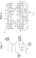
- Figure 1 conceptually shows components of an isolation system for an MRI magnet system 1 arranged in a "clam-shell" configuration according to a preferred aspect of the present invention.
- the isolation system is made up of a vibration isolation system 2 and an optional, adjustable balance mass 3.
- the vibration isolation system 2 includes a conceptual variable spring element 4 and a conceptual variable damper element 5.
- the spring element 4 and the damping element 5 may integrated into the same device or they may comprise different devices (i.e., in this case, the system 2 comprises two discrete devices). It should be noted that any or all of these conceptual elements 3, 4 and 5 should be broadly construed and include many elements which have similar performance characteristics.
- the spring element 4 includes mechanical springs, air isolators, piezoelectric actuator isolators, elastic webbing or other devices which provide frequency isolation.
- FIG. 2 illustrates a portion of an MRI system according to the first embodiment of the present invention.
- the MRI system includes an open MRI magnet system 10, which contains a first magnet assembly 12, a second magnet assembly 14 and at least one support member (such as the two support beams 16 and 18 that are shown in Figure 2), and a vibration isolation system 20.
- a support member such as the two support beams 16 and 18 that are shown in Figure 2
- a vibration isolation system 20 such as the two support beams 16 and 18 that are shown in Figure 2
- more than two support beams or other types of support members i.e., "C" shaped supports
- Additional parts of the MRI system such as the control electronics and cooling fluid supply pipes, are not shown in Figure 2 for clarity.
- the first assembly 12 has a longitudinally-extending and generally-vertically-aligned first axis 22, at least one superconductive main coil 24, and a first vacuum enclosure 26.
- “generally-vertically-aligned” is meant vertically aligned plus or minus twenty degrees.
- the at least one superconductive main coil 24 of the first assembly 12 is generally coaxially aligned with the first axis 22 and carries a first main electric current in a first direction.
- the first direction is defined to be either a clockwise or a counterclockwise circumferential direction about the first axis 22 with any slight longitudinal component of current direction being ignored.
- the first vacuum enclosure 26 encloses at least one superconductive main coil 24 of the first assembly 12 and preferably surrounds a first bore 70.
- a first magnet pole piece 68 is generally coaxially aligned with the first axis 22, is disposed inside the first bore 70 and outside the first vacuum enclosure 26, and is attached to the first vacuum enclosure 26.
- the second assembly 14 is longitudinally spaced apart from and disposed generally vertically below the first assembly 12.
- the second assembly 14 has a longitudinally-extending second axis 28, at least one superconductive main coil 30, and a second vacuum enclosure 32.
- the second axis 28 is generally coaxially aligned with the first axis 22.
- At least one superconductive main coil 30 of the second assembly 14 is generally coaxially aligned with the second axis 28 and carries a second main electric current in the previously-described first direction.
- the second vacuum enclosure 32 encloses the at least one superconductive main coil 30 of the second assembly 14 and preferably surrounds a second bore 74.
- a second magnet pole piece 72 is generally coaxially aligned with the second axis 28, is disposed inside the second bore 74 and outside the second vacuum enclosure 32, and is attached to the second vacuum enclosure 32.
- the vacuum enclosure 32 contains generally horizontally-aligned annular shaped walls 60 and 62 and circumferentially-extending walls 64 and 66. Walls 60, 62, 64 and 66 enclose the coil 30.
- At least one support member such as the support beams 16 and 18, has a first end 34 attached to the first assembly 12 and has a second end 36 attached to the second assembly 14.
- Each support beam or member is preferably made of a nonmagnetizable material or includes at least a nonmagnetizable material portion which blocks having a magnetizable path between its ends.
- Such nonmagnetizable material has a relative permeability of generally unity. Examples of nonmagnetizable materials include aluminum, copper, nonmagnetic stainless steel, plastic, wood, etc.
- the vibration isolation system 20 of the embodiment of Figure 2 contains of one or more isolators 120 positioned beneath the second (i.e., lower) assembly 14.
- the isolators 120 can be either passive or active isolators.
- passive pneumatic isolators such as Gimbal Piston or MaxDamp®
- active isolators such as STACIS® 2000 or 3000 Active Piezoelectric Vibration Control System units may be used.
- TMC Technical Manufacturing Corporation
- the pneumatic isolators work by the pressure in a volume acting on an area of a piston to support the load against the force of gravity.
- a reinforced rolling rubber diaphragm forms a seal between the air tank and the piston.
- the pressure in the isolator is controlled by a height control valve which senses the height of the payload, and inflates the isolator until the payload is "floating.”
- the isolator assembly 120 acts as a spring element and as a damper.
- active isolators 120 actively controlled piezoelectric actuators are used to cancel the vibration on the payload (i.e., the MRI magnet system).
- This system contains an "inner-loop" damping function, in which vibration sensors measure floor noise, which is conditioned and used to cancel vibration, and an “outer-loop” damping function, in which vibration sensors mounted on payload side of the system measure the residual vibration on the payload, which is used in a feed back loop to further reduce vibration.
- any other commercial off the shelf or custom build isolator can be used instead, providing that it provides the appropriate vibration isolation.
- the isolators 120 provide the only weight-bearing support for the second assembly 14 (and preferably for the entire magnet system 10).
- the isolators 120 are positioned with respect to the second axis 28 in such a manner that each isolator bears a desired load.
- four to twenty, preferably ten isolators 120 may be arranged within the footprint of the second assembly 14 to support the magnet system 10.
- the isolators 120 are attached to a floor 42 of a building or other support for the MRI system.
- the isolation system 20 may be exposed (i.e., visible below the magnet system 10) or it may be enclosed. Preferably, the isolation system 20 is enclosed by an enclosure (not shown in Figure 2 for clarity) for aesthetic, sanitary, acoustical reasons. It is desirable to have the isolation system 20 contained within the footprint of the MRI magnet system 10, whether it is enclosed or not enclosed.
- the vibration isolation system 20 provides an adjustable damping and spring constant. This allows the adjustment of the natural frequency of the MRI magnet system 10 to a site defined region. This can be done both at the manufacturer's facility and at the MRI system installation site.
- the isolation system 20 is preferably selected such that its damping function minimizes the magnet system Q factor and controls the bandwidth of the vibrational response at the predominant exciting frequencies.
- the isolation system also preferably provides a sufficiently high damping to improve the gravitational stability of the magnet system.
- the isolators 120 are selected such that they can provide the above functions.
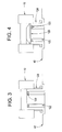
- the vibration isolation system 20 is used in a retrofit of a preexisting (i.e., a prior art) MRI system, as shown in Figure 3.
- a prior art MRI system is ordinarily rigidly attached (i.e., bolted, clamped and/or welded) to a floor of a building by support structure, such as by legs or by a curved skirt 124, as described in U.S. Patent No. 6,198,371.
- the support legs or skirt 124 are not removed from the MRI system.
- the vibration isolation system 20 can be colocated with the supports. All that is necessary is to raise the height of the MRI magnet assembly 10 so that the bottom of the preexisting support structure does not contact the floor 42 of the building. As shown in Figure 3, posts 122 or other load bearing objects are placed under the isolators 120 to elevate the MRI magnet assembly 10 to a height sufficient to prevent the support legs or skirt from contacting the building floor 42.
- an optional structural holder 126 is located between the isolators 120 and the lower assembly 14 of the magnet system 10, as shown in Figure 4.
- the holder 126 may be one or more a metal or other plates which are placed between the isolators 120 and the lower assembly 14.
- the holder is preferably lightweight, compact in size and provides a level surface for the isolators 120.
- the holder 126 is advantageous when the lower surface of the second assembly 14 is not sufficiently level or does not have a desired shape or material to allow the isolators 120 to be connected directly to the second assembly.
- the holder 126 may be particularly advantageous for retrofitting a preexisting MRI system, where the second assembly 14 was not designed to be directly connected to the isolators 120.
- a balance mass 128 is added to the isolation system 20, as shown in Figure 5.
- the balance mass 128 is supported by a balance mass support 130 that is connected the structural holder 126.
- the balance mass 128 can be connected directly to the structural holder 126, or directly to the lower assembly 14 of the magnet system if the holder 126 is omitted.
- the balance mass 128 may be any heavy object, such as metal or ceramic bars or weights.
- the optional posts 122 are also used in combination with the balance mass 128 to raise the isolators off the floor 42 to provide sufficient clearance for the placement of the balance mass, as shown in Figure 5.
- the balance mass 128 is preferably adjustable to allow the center of gravity of the magnet assembly 10 to be changed to improve gravitational stability.
- the balance mass 128 may be adjusted by raising or lowering it with respect to the magnet system 10. The adjustments may be made, for example, by manually (i.e., by using a jackscrew or similar elements), electrically or hydraulically raising or lowering the support 130. Alternatively, the adjustments may be made by adding or removing mass from the balance mass 128. For example, one or more weight providing plates may be added or removed from the balance mass for adjustment.
- the balance mass 128 is adjustable on site (i.e., in the building that will house the MRI system), after the environmental vibrations at this site have been determined.
- a structure supported below its center of mass is inherently unstable because as the structure tilts, its center of mass moves horizontally in a way that wants to further increase the tilt.
- the maximum allowed height of the magnet system center of mass improves with the square of the isolator 120 separation, and the stiffness of the isolators 120.
- the balance mass 128 lowers the center of mass of the structure to improve the gravitational stability of the structure. Supporting the magnet system 10 closer to its center of mass will reduce the rocking of the magnet system 10 and thus improve the MRI image.
- the balance mass 128 can be configured in such a way as to work with the isolators to change the system natural frequency and reduce the magnitude of the vibrations experienced by the magnet system 10.
- the fifth embodiment of the present invention is illustrated in Figure 6, where the balance mass 128 is used with pneumatic (i.e., air) isolators 120.
- the isolators 120 are supplied with air (or another gas) from an air source 132 through a line 134.
- a height control valve 136 is also provided to control the flow of air through the line 134 to control the pressure in the isolators 120.
- the valve 136 may be manually or computer controlled.
- Figure 6 also shows an alternative configuration of the isolation system 20, where the optional balance mass 128 is connected directly to the structural holder 126, and the balance mass support is omitted.
- the MRI system may be installed at a particular site as follows.
- the environmental disturbances and vibrations at a particular site are measured.
- the measurements are preferably made before the MRI system is installed at a particular site.
- the isolators are selected such that the natural frequency of the MRI magnet system and the damping of the isolators will provide significant reduction on ground vibration transmissibility over the entire frequency band.
- a high damping isolator system is preferably selected when low frequency excitation (i.e., vibrations or disturbances) is significant at the particular site.
- a low damping isolator system is preferably selected if the particular site has only high frequency disturbances or vibrations.
- the damping of the isolators is adjusted to minimize the magnet system Q factor and control the bandwidth of the vibrational response of the magnet system at the predominant exciting frequencies. If a balance mass 128 is present, then the balance mass is adjusted to optimize the center of gravity of the system and the natural frequency of the MRI magnets. Thus, the frequency and damping are site tunable because they are adjusted to be optimized for a particular site. The adjustments may be made before or after the MRI system has been installed at a particular site (i.e., attached to a floor 42 of the building that houses the MRI system).
Landscapes
- Physics & Mathematics (AREA)
- Condensed Matter Physics & Semiconductors (AREA)
- General Physics & Mathematics (AREA)
- Magnetic Resonance Imaging Apparatus (AREA)
Abstract
Description
- The present invention relates generally to a magnetic resonance imaging (MRI) system, and more particularly to an open MRI magnet system having a vibration isolation system.
- MRI magnets include resistive and superconductive MRI magnets used in various applications, such as medical diagnostics. Known superconductive MRI magnets include liquid-helium-cooled, cryocooler-cooled, and hybrid-cooled superconductive magnets. Typically, the superconductive coil assembly includes a superconductive main coil surrounded by a thermal shield surrounded by a vacuum enclosure. A cryocooler-cooled MRI magnet typically also includes a cryocooler coldhead externally mounted to the vacuum enclosure, having its first stage in solid conduction thermal contact with the thermal shield, and having its second stage in solid conduction thermal contact with the superconductive main coil. A liquid-helium-cooled MRI magnet typically also includes a liquid-helium vessel surrounding the superconductive main coil with the thermal shield surrounding the liquid-helium vessel. A hybrid-cooled MRI magnet uses both liquid helium (or other liquid or gaseous cryogen) and a cryocooler coldhead, and includes designs wherein the first stage of the cryocooler coldhead is in solid conduction thermal contact with the thermal shield and wherein the second stage of the cryocooler coldhead penetrates the liquid-helium vessel to recondense "boiled-off" helium.
- Known resistive and superconductive MRI magnet designs include closed MRI magnets and open MRI magnets. Closed MRI magnets typically have a single, tubular-shaped resistive or superconductive coil assembly having a bore. The coil assembly includes several radially-aligned and longitudinally spaced-apart resistive or superconductive main coils each carrying a large, identical electric current in the same direction. The main coils are thus designed to create a magnetic field of high uniformity within a typically spherical imaging volume centered within the MRI magnet's bore where the object to be imaged is placed.
- Open MRI magnets, including "C" shape and support-post MRI magnets, typically employ two spaced-apart coil assemblies with the space between the assemblies containing the imaging volume and allowing for access by medical personnel for surgery or other medical procedures during magnetic resonance imaging. The patient may be positioned in that space or also in the bore of the toroidal-shaped coil assemblies. The open space helps the patient overcome any feelings of claustrophobia that may be experienced in a closed MRI magnet design.
- It is also known in open MRI magnet designs to place an iron pole piece in the bore of a resistive or superconductive coil assembly. The iron pole piece enhances the strength of the magnetic field and, by shaping the surface of the pole piece, magnetically shims the magnet improving the homogeneity of the magnetic field. Nonmagnetizable support posts are connected to the face of the pole pieces. It is additionally known in horizontally-aligned open MRI magnets to support the magnet on the floor using two spaced-apart feet attached to each assembly, such feet raising the assemblies to provide room underneath the assemblies for necessary wires, pipes, etc.
- The sharpness of an MRI image depends, in part, on the magnetic field in the imaging volume being time-constant and highly uniform. However, the magnetic field in prior art systems suffers time and spatial deformation caused by vibrations from environmental disturbances. Minor relative motions between any of the magnetic elements will cause significant magnetic field disturbances, thus reducing the image quality.
- In accordance with one preferred aspect of the present invention, there is provided an open MRI system, comprising an open MRI magnet system, and a vibration isolation system adapted to support the MRI magnet system.
- In accordance with another preferred aspect of the present invention, there is provided an open MRI system comprising a first and a second assembly. Each assembly comprises a longitudinally-extending and generally-vertically-aligned axis, at least one superconductive main coil positioned around the axis and carrying a main electric current in a first direction, and a vacuum enclosure enclosing said at least one superconductive main coil. The system further comprises at least one support beam external to the vacuum enclosures, having a first end attached to said first assembly and having a second end attached to said second assembly. The system further comprises a vibration isolation system.
- In accordance with another preferred aspect of the present invention, there is provided a method of installing an open MRI system, comprising measuring environmental disturbances and vibrations at a first site, and providing the open MRI system which comprises a vibration isolation system and an open magnet system. The method further comprises selecting the vibration isolation system based on the measuring step, and installing the MRI system at the first site.
- In accordance with another preferred aspect of the present invention, there is provided a method of retrofitting a preexisting open MRI system comprising attaching a vibration isolation system to the magnet system of the preexisting MRI system.
- Embodiments of the invention will now be described, by way of example, with reference to the accompanying drawings, in which:
- Figures 1-6 are schematic side cross sectional views of portions of an MRI system according to the preferred embodiments of the present invention. In the drawings, the same numerals represent the same elements throughout.
-
- The present inventors have realized that all sites containing an MRI system are subject to some kind of environmental disturbance, such as from electrical or mechanical equipment installed within the same building. The environmental disturbances or vibrations excite the MRI system magnets through the MRI system's attachment to the building, such as through the floor, walls or ceiling of a room of a building containing the MRI system. The most significant such attachment is the foot support, which is fastened to the floor to secure the magnets of the MRI system. The foot support transmits the environmental disturbances and vibrations to the magnets of the MRI system, thus degrading the image quality.
- The present inventors have determined that by using a tunable vibration isolation system instead of conventional feet or other rigid support structures found on horizontally-aligned open MRI magnets, allows the natural frequency of the MRI magnets to be shifted to a site defined value. This allows the natural frequency of the MRI magnets to be set at a value at which the sensitivity of the magnets to vibration at the dominant frequencies imparted to the magnets by environmental disturbances is reduced or minimized. If desired, an optional adjustable balance mass may be used in combination with the vibration isolation system to improve the gravity stability of the vibration isolation system when pneumatic isolators are used.
- The vibration isolation system is particularly advantageous when used with in a vertically-aligned open MRI magnet system arranged in a "clam-shell" configuration. The superconductive coils of the magnet assemblies of such MRI systems are especially subject to vibrations from the environment because the magnet assemblies are attached by only two support members, especially when the two support members are not diametrically aligned to the diameter line of the magnet assemblies. Such clam-shell support is a very open support, providing ease of patient table access to the imaging volume and providing ease of patient positioning within the imaging volume. Engineering analysis shows that the vibration isolation system reduces magnet vibrations in a vertically-aligned open MRI magnet having a "clam-shell" configuration. However, the isolation system may be used for MRI systems having a configuration other than a "clam-shell" configuration, if desired.
- The vibration isolation system is also advantageous because it is fairly inexpensive. The isolation system may utilize commercially available isolators which are configured to support a new MRI magnet system or retrofitted to an preexisting MRI magnet system.
- Figure 1 conceptually shows components of an isolation system for an
MRI magnet system 1 arranged in a "clam-shell" configuration according to a preferred aspect of the present invention. The isolation system is made up of avibration isolation system 2 and an optional,adjustable balance mass 3. Thevibration isolation system 2 includes a conceptualvariable spring element 4 and a conceptualvariable damper element 5. Thespring element 4 and thedamping element 5 may integrated into the same device or they may comprise different devices (i.e., in this case, thesystem 2 comprises two discrete devices). It should be noted that any or all of theseconceptual elements spring element 4 includes mechanical springs, air isolators, piezoelectric actuator isolators, elastic webbing or other devices which provide frequency isolation. - Figure 2 illustrates a portion of an MRI system according to the first embodiment of the present invention. The MRI system includes an open
MRI magnet system 10, which contains afirst magnet assembly 12, asecond magnet assembly 14 and at least one support member (such as the twosupport beams vibration isolation system 20. However, more than two support beams or other types of support members (i.e., "C" shaped supports) may be provided. Additional parts of the MRI system, such as the control electronics and cooling fluid supply pipes, are not shown in Figure 2 for clarity. - The
first assembly 12 has a longitudinally-extending and generally-vertically-alignedfirst axis 22, at least one superconductivemain coil 24, and afirst vacuum enclosure 26. By "generally-vertically-aligned" is meant vertically aligned plus or minus twenty degrees. The at least one superconductivemain coil 24 of thefirst assembly 12 is generally coaxially aligned with thefirst axis 22 and carries a first main electric current in a first direction. The first direction is defined to be either a clockwise or a counterclockwise circumferential direction about thefirst axis 22 with any slight longitudinal component of current direction being ignored. Thefirst vacuum enclosure 26 encloses at least one superconductivemain coil 24 of thefirst assembly 12 and preferably surrounds afirst bore 70. A firstmagnet pole piece 68 is generally coaxially aligned with thefirst axis 22, is disposed inside thefirst bore 70 and outside thefirst vacuum enclosure 26, and is attached to thefirst vacuum enclosure 26. - The
second assembly 14 is longitudinally spaced apart from and disposed generally vertically below thefirst assembly 12. Thesecond assembly 14 has a longitudinally-extendingsecond axis 28, at least one superconductivemain coil 30, and asecond vacuum enclosure 32. Thesecond axis 28 is generally coaxially aligned with thefirst axis 22. At least one superconductivemain coil 30 of thesecond assembly 14 is generally coaxially aligned with thesecond axis 28 and carries a second main electric current in the previously-described first direction. Thesecond vacuum enclosure 32 encloses the at least one superconductivemain coil 30 of thesecond assembly 14 and preferably surrounds asecond bore 74. A secondmagnet pole piece 72 is generally coaxially aligned with thesecond axis 28, is disposed inside thesecond bore 74 and outside thesecond vacuum enclosure 32, and is attached to thesecond vacuum enclosure 32. Thevacuum enclosure 32 contains generally horizontally-aligned annular shapedwalls walls Walls coil 30. - At least one support member, such as the support beams 16 and 18, has a
first end 34 attached to thefirst assembly 12 and has asecond end 36 attached to thesecond assembly 14. Each support beam or member is preferably made of a nonmagnetizable material or includes at least a nonmagnetizable material portion which blocks having a magnetizable path between its ends. Such nonmagnetizable material has a relative permeability of generally unity. Examples of nonmagnetizable materials include aluminum, copper, nonmagnetic stainless steel, plastic, wood, etc. - The
vibration isolation system 20 of the embodiment of Figure 2 contains of one ormore isolators 120 positioned beneath the second (i.e., lower)assembly 14. In this embodiment, theisolators 120 can be either passive or active isolators. For example, passive pneumatic isolators, such as Gimbal Piston or MaxDamp®, or active isolators, such as STACIS® 2000 or 3000 Active Piezoelectric Vibration Control System units may be used. These isolators are made by Technical Manufacturing Corporation (TMC) in Peabody, Massachusetts (see www.techmfg.com). - The pneumatic isolators work by the pressure in a volume acting on an area of a piston to support the load against the force of gravity. A reinforced rolling rubber diaphragm forms a seal between the air tank and the piston. The pressure in the isolator is controlled by a height control valve which senses the height of the payload, and inflates the isolator until the payload is "floating." Thus, in this case, the
isolator assembly 120 acts as a spring element and as a damper. - In the
active isolators 120, actively controlled piezoelectric actuators are used to cancel the vibration on the payload (i.e., the MRI magnet system). This system contains an "inner-loop" damping function, in which vibration sensors measure floor noise, which is conditioned and used to cancel vibration, and an "outer-loop" damping function, in which vibration sensors mounted on payload side of the system measure the residual vibration on the payload, which is used in a feed back loop to further reduce vibration. It should be noted that any other commercial off the shelf or custom build isolator can be used instead, providing that it provides the appropriate vibration isolation. - In the embodiment of Figure 2, the
isolators 120 provide the only weight-bearing support for the second assembly 14 (and preferably for the entire magnet system 10). Theisolators 120 are positioned with respect to thesecond axis 28 in such a manner that each isolator bears a desired load. For example, four to twenty, preferably tenisolators 120 may be arranged within the footprint of thesecond assembly 14 to support themagnet system 10. Theisolators 120 are attached to afloor 42 of a building or other support for the MRI system. - The
isolation system 20 may be exposed (i.e., visible below the magnet system 10) or it may be enclosed. Preferably, theisolation system 20 is enclosed by an enclosure (not shown in Figure 2 for clarity) for aesthetic, sanitary, acoustical reasons. It is desirable to have theisolation system 20 contained within the footprint of theMRI magnet system 10, whether it is enclosed or not enclosed. - Preferably, the
vibration isolation system 20 provides an adjustable damping and spring constant. This allows the adjustment of the natural frequency of theMRI magnet system 10 to a site defined region. This can be done both at the manufacturer's facility and at the MRI system installation site. Theisolation system 20 is preferably selected such that its damping function minimizes the magnet system Q factor and controls the bandwidth of the vibrational response at the predominant exciting frequencies. Furthermore, the isolation system also preferably provides a sufficiently high damping to improve the gravitational stability of the magnet system. Thus, theisolators 120 are selected such that they can provide the above functions. - In a second preferred embodiment, the
vibration isolation system 20 is used in a retrofit of a preexisting (i.e., a prior art) MRI system, as shown in Figure 3. A prior art MRI system is ordinarily rigidly attached (i.e., bolted, clamped and/or welded) to a floor of a building by support structure, such as by legs or by acurved skirt 124, as described in U.S. Patent No. 6,198,371. In retrofitting the MRI system, in order to decrease the retrofitting costs, after the MRI system is detached from the floor (i.e., unbolted, unclamped, etc), the support legs orskirt 124 are not removed from the MRI system. Thus, instead of removing the existing supports, thevibration isolation system 20 can be colocated with the supports. All that is necessary is to raise the height of theMRI magnet assembly 10 so that the bottom of the preexisting support structure does not contact thefloor 42 of the building. As shown in Figure 3,posts 122 or other load bearing objects are placed under theisolators 120 to elevate theMRI magnet assembly 10 to a height sufficient to prevent the support legs or skirt from contacting thebuilding floor 42. - In a third preferred embodiment of the present invention, an optional
structural holder 126 is located between theisolators 120 and thelower assembly 14 of themagnet system 10, as shown in Figure 4. Theholder 126 may be one or more a metal or other plates which are placed between theisolators 120 and thelower assembly 14. The holder is preferably lightweight, compact in size and provides a level surface for theisolators 120. Theholder 126 is advantageous when the lower surface of thesecond assembly 14 is not sufficiently level or does not have a desired shape or material to allow theisolators 120 to be connected directly to the second assembly. Thus, theholder 126 may be particularly advantageous for retrofitting a preexisting MRI system, where thesecond assembly 14 was not designed to be directly connected to theisolators 120. - In a fourth preferred embodiment of the present invention, a
balance mass 128 is added to theisolation system 20, as shown in Figure 5. In this embodiment, thebalance mass 128 is supported by abalance mass support 130 that is connected thestructural holder 126. Alternatively, thebalance mass 128 can be connected directly to thestructural holder 126, or directly to thelower assembly 14 of the magnet system if theholder 126 is omitted. Thebalance mass 128 may be any heavy object, such as metal or ceramic bars or weights. Preferably, theoptional posts 122 are also used in combination with thebalance mass 128 to raise the isolators off thefloor 42 to provide sufficient clearance for the placement of the balance mass, as shown in Figure 5. - The
balance mass 128 is preferably adjustable to allow the center of gravity of themagnet assembly 10 to be changed to improve gravitational stability. Thebalance mass 128 may be adjusted by raising or lowering it with respect to themagnet system 10. The adjustments may be made, for example, by manually (i.e., by using a jackscrew or similar elements), electrically or hydraulically raising or lowering thesupport 130. Alternatively, the adjustments may be made by adding or removing mass from thebalance mass 128. For example, one or more weight providing plates may be added or removed from the balance mass for adjustment. Most preferably, thebalance mass 128 is adjustable on site (i.e., in the building that will house the MRI system), after the environmental vibrations at this site have been determined. - A structure supported below its center of mass is inherently unstable because as the structure tilts, its center of mass moves horizontally in a way that wants to further increase the tilt. The maximum allowed height of the magnet system center of mass improves with the square of the
isolator 120 separation, and the stiffness of theisolators 120. Thebalance mass 128 lowers the center of mass of the structure to improve the gravitational stability of the structure. Supporting themagnet system 10 closer to its center of mass will reduce the rocking of themagnet system 10 and thus improve the MRI image. Thebalance mass 128 can be configured in such a way as to work with the isolators to change the system natural frequency and reduce the magnitude of the vibrations experienced by themagnet system 10. - The fifth embodiment of the present invention is illustrated in Figure 6, where the
balance mass 128 is used with pneumatic (i.e., air)isolators 120. Theisolators 120 are supplied with air (or another gas) from anair source 132 through aline 134. Aheight control valve 136 is also provided to control the flow of air through theline 134 to control the pressure in theisolators 120. Thevalve 136 may be manually or computer controlled. Figure 6 also shows an alternative configuration of theisolation system 20, where theoptional balance mass 128 is connected directly to thestructural holder 126, and the balance mass support is omitted. - The MRI system may be installed at a particular site as follows. The environmental disturbances and vibrations at a particular site are measured. The measurements are preferably made before the MRI system is installed at a particular site.
- Then, based on the measurements, the isolators are selected such that the natural frequency of the MRI magnet system and the damping of the isolators will provide significant reduction on ground vibration transmissibility over the entire frequency band. A high damping isolator system is preferably selected when low frequency excitation (i.e., vibrations or disturbances) is significant at the particular site. A low damping isolator system is preferably selected if the particular site has only high frequency disturbances or vibrations.
- Furthermore, the damping of the isolators is adjusted to minimize the magnet system Q factor and control the bandwidth of the vibrational response of the magnet system at the predominant exciting frequencies. If a
balance mass 128 is present, then the balance mass is adjusted to optimize the center of gravity of the system and the natural frequency of the MRI magnets. Thus, the frequency and damping are site tunable because they are adjusted to be optimized for a particular site. The adjustments may be made before or after the MRI system has been installed at a particular site (i.e., attached to afloor 42 of the building that houses the MRI system). - It should be noted that additional superconductive main coils, superconductive shielding coils, superconductive correction coils, and magnetizable rings may be present, as is known to the artisan, but such coils and rings have been omitted from the figures for clarity. Likewise, coil forms (if needed) to support the superconductive main coils and spacers to position a thermal shield with respect to a cryogenic vessel and to position a thermal shield with respect to a vacuum enclosure have been omitted from the figures for clarity but are well known to those skilled in the art.
- For completeness, various aspects of the invention are set out in the following numbered clauses:
- 1. An open MRI system comprising:
- an open MRI magnet system (1, 10); and
- a vibration isolation system (2, 20) adapted to support the MRI magnet system.
- 2. The open MRI system of
clause 1, wherein a spring constant and damping of the vibration isolation system (2, 20) are adjustable. - 3. The open MRI system of
clause 1, wherein the vibration isolation system (2, 20) comprises a plurality of pneumatic isolators (120). - 4. The open MRI system of
clause 1, wherein the vibration isolation system (2, 20) comprises a plurality of active vibration control isolators (120). - 5. The open MRI system of
clause 1, further comprising a balance mass (3, 128). - 6. The open MRI system of
clause 5, wherein the balance mass (3, 128) is adjustable. - 7. The open MRI system of
clause 1, wherein the vibration isolation system (2, 20) is secured to a floor and the MRI magnet system (1, 10) is attached over the vibration isolation system. - 8. The open MRI system of
clause 1, wherein the vibration isolation system (2, 20) is configured within a footprint of the MRI magnet system (1, 10). - 9. The open MRI system of
clause 1, further comprising a structural holder (126) positioned between the vibration isolation system (20) and the MRI magnet system (10). - 10. The open MRI system of
clause 1, wherein the vibration isolation system (20) is retrofitted to a preexisting MRI magnet system(10). - 11. The open MRI system of
clause 10, wherein the vibration isolation system (20) is mounted on posts (122) such that MRI magnet system (10) supports (124) do not contact a floor (42) of a site where the MRI magnet system is located. - 12. The open MRI system of
clause 1, wherein the vibration isolation system (2, 20) is site tunable. - 13. The open MRI system of clause 11, wherein the vibration isolation system (2, 20) is tuned to minimize the magnet system Q factor and to control a bandwidth of the MRI magnet system vibration response at a predominant MRI magnet exciting frequencies.
- 14. An open MRI system comprising:
- (a) a first assembly (12) comprising:
- (1) a longitudinally-extending and generally-vertically-aligned first axis (22);
- (2) at least one superconductive main coil (24) positioned around said first axis and carrying a first main electric current in a first direction; and
- (3) a first vacuum enclosure (26) enclosing said at least one superconductive main coil of said first assembly;
- (b) a second assembly (14) longitudinally spaced apart from and
disposed below said first assembly (12), comprising:
- (1) a longitudinally-extending second axis (28) generally coaxially aligned with said first axis;
- (2) at least one superconductive main coil (30) positioned around said second axis and carrying a second main electric current in said first direction; and
- (3) a second vacuum enclosure (32) enclosing said at least one superconductive main coil of second assembly;
- (c) at least one support beam (16, 18) external to said first and second vacuum enclosure having a first end (34) attached to said first assembly and having a second end (36) attached to said second assembly; and
- (d) a vibration isolation system (20).
- 15. The open MRI system of
clause 14, wherein a spring constant and damping of the vibration isolation system (20) are adjustable. - 16. The open MRI system of
clause 14, wherein the vibration isolation system (20) comprises a plurality of pneumatic isolators (120). - 17. The open MRI system of
clause 14, wherein the vibration isolation system (20) comprises a plurality of active vibration control isolators (120). - 18. The open MRI system of
clause 14, further comprising an adjustable balance mass (128). - 19. The open MRI system of
clause 14, wherein the vibration isolation system (20) is secured to a floor (42) and the MRI magnet system (10) is attached over the vibration isolation system (20). - 20. The open MRI system of
clause 14, wherein the vibration isolation system (20) is configured within a footprint of the MRI magnet system (10). - 21. The open MRI system of
clause 14, wherein: - the vibration isolation system (20) is retrofitted to a preexisting MRI magnet system (16); and
- the vibration isolation system is mounted on posts (122) such that MRI magnet system supports (124) do not contact a floor (42) of a site where the MRI magnet system is provided.
- 22. The open MRI system of
clause 14, wherein the vibration isolation system (20) is site tuned to minimize the magnet system Q factor and to control a bandwidth of the MRI magnet system vibration response at a predominant MRI magnet exciting frequencies. - 23. The method of installing an open MRI system, comprising:
- providing the open MRI system which comprises a vibration isolation system and an open magnet system;
- measuring environmental disturbances and vibrations at a first site;
- selecting the vibration isolation system based on the measuring step; and
- installing the MRI system at the first site.
- 24. The method of clause 23, wherein the step of selecting comprises:
- selecting a high damping isolation system when significant low frequency vibrations or disturbances are measured at the first site; or
- selecting a low damping isolation system when only high frequency disturbances or vibrations are measured at the first site.
- 25. The method of
clause 24, further comprising adjusting a balance mass to optimize a center of gravity of the magnet system. - 26. The method of clause 25, wherein the step of adjusting is performed before or after the step of installing.
- 27. The method of clause 23, wherein the step of measuring is performed before the step of installing.
- 28. The method of clause 23, wherein the steps of measuring and selecting are performed before the step of installing.
- 29. The method of clause 23, further comprising adjusting the damping of the vibration isolation system to minimize the magnet system Q factor and control a bandwidth of a vibrational response at predominant exciting frequencies.
- 30. The method of clause 23, wherein the vibration isolation system comprises a plurality of pneumatic isolators.
- 31. The method of clause 23, wherein the vibration isolation system comprises a plurality of active vibration control isolators.
- 32. The method of clause 23, wherein the step of installing comprises securing the vibration isolation system to a floor, such that the MRI magnet system is provided over the vibration isolation system.
- 33. The method of clause 23, further comprising:
- detaching the MRI system from a floor; and
- retrofitting the vibration isolation system to the magnet system of the MRI system prior to the step of installing the MRI system at the first site.
- 34. A method of retrofitting a preexisting open MRI system comprising attaching a vibration isolation system to a magnet system of the preexisting MRI system.
- 35. The method of
clause 34, further comprising detaching the magnet system from a floor prior to the step of attaching the a vibration isolation system. - 36. The method of
clause 34, wherein the vibration isolation system comprises a plurality of pneumatic isolators. - 37. The method of
clause 34, wherein the vibration isolation system comprises a plurality of active vibration control isolators. - 38. The method of
clause 34, further comprising securing a plurality of posts to a floor and securing the vibration isolation system to the posts, such that the MRI magnet system is provided over the vibration isolation system and such that supports of the preexisting MRI system do not contact the floor. -
Claims (10)
- An open MRI system comprising:an open MRI magnet system (1, 10); anda vibration isolation system (2, 20) adapted to support the MRI magnet system.
- An open MRI system comprising:(a) a first assembly (12) comprising:(1) a longitudinally-extending and generally-vertically-aligned first axis (22);(2) at least one superconductive main coil (24) positioned around said first axis and carrying a first main electric current in a first direction; and(3) a first vacuum enclosure (26) enclosing said at least one superconductive main coil of said first assembly;(b) a second assembly (14) longitudinally spaced apart from and disposed below said first assembly (12), comprising:(1) a longitudinally-extending second axis (28) generally coaxially aligned with said first axis;(2) at least one superconductive main coil (30) positioned around said second axis and carrying a second main electric current in said first direction; and(3) a second vacuum enclosure (32) enclosing said at least one superconductive main coil of second assembly;(c) at least one support beam (16, 18) external to said first and second vacuum enclosure having a first end (34) attached to said first assembly and having a second end (36) attached to said second assembly; and(d) a vibration isolation system (20).
- The open MRI system of claim 1 or claim 2, wherein a spring constant and damping of the vibration isolation system (2, 20) are adjustable.
- The open MRI system of claim 1 or claim 2, wherein the vibration isolation system (2, 20) comprises a plurality of pneumatic isolators (120).
- The open MRI system of claim 1 or claim 2, wherein the vibration isolation system (2, 20) comprises a plurality of active vibration control isolators (120).
- 'The open MRI system of claim 1 or claim 2, further comprising an adjustable balance mass (3, 128).
- The open MRI system of claim 1 or claim 2, wherein the vibration isolation system (2, 20) is secured to a floor and the MRI magnet system (1, 10) is attached over the vibration isolation system.
- The method of installing an open MRI system, comprising:providing the open MRI system which comprises a vibration isolation system and an open magnet system;measuring environmental disturbances and vibrations at a first site;selecting the vibration isolation system based on the measuring step; andinstalling the MRI system at the first site.
- The method of claim 8, wherein the step of selecting comprises:selecting a high damping isolation system when significant low frequency vibrations or disturbances are measured at the first site; orselecting a low damping isolation system when only high frequency disturbances or vibrations are measured at the first site.
- A method of retrofitting a preexisting open MRI system comprising attaching a vibration isolation system to a magnet system of the preexisting MRI system.
Applications Claiming Priority (2)
| Application Number | Priority Date | Filing Date | Title |
|---|---|---|---|
| US09/682,519 US7345559B2 (en) | 2001-09-13 | 2001-09-13 | High field open MRI magnet isolation system and method |
| US682519 | 2001-09-13 |
Publications (2)
| Publication Number | Publication Date |
|---|---|
| EP1293795A1 true EP1293795A1 (en) | 2003-03-19 |
| EP1293795B1 EP1293795B1 (en) | 2008-03-12 |
Family
ID=24740054
Family Applications (1)
| Application Number | Title | Priority Date | Filing Date |
|---|---|---|---|
| EP02256325A Expired - Lifetime EP1293795B1 (en) | 2001-09-13 | 2002-09-12 | High field open MRI magnet isolation system and method |
Country Status (5)
| Country | Link |
|---|---|
| US (3) | US7345559B2 (en) |
| EP (1) | EP1293795B1 (en) |
| JP (1) | JP4141212B2 (en) |
| CN (1) | CN100464700C (en) |
| DE (1) | DE60225515T2 (en) |
Cited By (2)
| Publication number | Priority date | Publication date | Assignee | Title |
|---|---|---|---|---|
| WO2008023317A3 (en) * | 2006-08-22 | 2008-05-08 | Koninkl Philips Electronics Nv | Magnetic resonance imaging system with reduced unintentional mechanical movements |
| EP1826582A3 (en) * | 2006-02-24 | 2010-03-24 | Hitachi, Ltd. | MRI apparatus involving damping of vibrations |
Families Citing this family (25)
| Publication number | Priority date | Publication date | Assignee | Title |
|---|---|---|---|---|
| US7196519B2 (en) * | 2000-07-28 | 2007-03-27 | Fonar Corporation | Stand-up vertical field MRI apparatus |
| DE10143048C1 (en) * | 2001-09-03 | 2003-04-17 | Siemens Ag | Magnetic resonance tomography device with noise suppression by damping mechanical vibrations |
| US7345559B2 (en) * | 2001-09-13 | 2008-03-18 | General Electric Company | High field open MRI magnet isolation system and method |
| JP2005535110A (en) * | 2002-06-25 | 2005-11-17 | タイコ・エレクトロニクス・コーポレイション | Integrated devices that provide overcurrent and overvoltage protection and common mode filtering for data bus interfaces |
| CN100434929C (en) * | 2002-11-15 | 2008-11-19 | 皇家飞利浦电子股份有限公司 | Magnetic resonance imaging system with gradient magnet system using balance components |
| JP3891947B2 (en) * | 2003-03-07 | 2007-03-14 | ジーイー・メディカル・システムズ・グローバル・テクノロジー・カンパニー・エルエルシー | Magnetic resonance imaging device |
| US6894498B2 (en) * | 2003-03-12 | 2005-05-17 | Mrscience Llc | Active vibration compensation for MRI gradient coil support to reduce acoustic noise in MRI scanners |
| JP4352120B2 (en) * | 2003-03-18 | 2009-10-28 | 独立行政法人理化学研究所 | Nuclear magnetic resonance apparatus |
| JP3587844B1 (en) * | 2003-11-17 | 2004-11-10 | 株式会社日立製作所 | Superconducting magnet apparatus and magnetic resonance imaging apparatus using the same |
| US6812705B1 (en) * | 2003-12-05 | 2004-11-02 | General Electric Company | Coolant cooled RF body coil |
| US10791957B1 (en) * | 2006-11-09 | 2020-10-06 | Fonar Corporation | Magnetic resonance imaging |
| WO2012174041A2 (en) * | 2011-06-13 | 2012-12-20 | Edelstein William A | Magnetic resonance imaging (mri) device noise dampening system |
| GB2497342B (en) * | 2011-12-08 | 2014-06-18 | Siemens Plc | Vibration isolation for superconducting magnets |
| US9322892B2 (en) | 2011-12-20 | 2016-04-26 | General Electric Company | System for magnetic field distortion compensation and method of making same |
| US9279871B2 (en) * | 2011-12-20 | 2016-03-08 | General Electric Company | System and apparatus for compensating for magnetic field distortion in an MRI system |
| GB2503460B (en) * | 2012-06-26 | 2014-08-13 | Siemens Plc | Method and apparatus for reduction of gradient coil vibration in MRI systems |
| US9274188B2 (en) | 2012-11-30 | 2016-03-01 | General Electric Company | System and apparatus for compensating for magnetic field distortion in an MRI system |
| US9458907B2 (en) | 2014-10-02 | 2016-10-04 | Honeywell International Inc. | Vibration isolation systems including multi-parameter isolators providing piezoelectric-based damping |
| EP3749666A1 (en) | 2018-02-08 | 2020-12-16 | Yissum Research Development Company of the Hebrew University of Jerusalem Ltd. | Heteroaryl compounds, pharmaceutical compositions thereof, and their therapeutic use |
| US11859759B2 (en) * | 2018-09-05 | 2024-01-02 | Synaptive Medical Inc. | Support stand for magnetic resonance imaging scanner |
| GB2582009B (en) | 2019-03-08 | 2021-04-07 | Siemens Healthcare Ltd | Split magnet with rotating central component |
| WO2020200437A1 (en) * | 2019-04-02 | 2020-10-08 | Siemens Healthcare Limited | Electromagnet for mri with mechanical support structure |
| BR112021024330A2 (en) | 2019-06-03 | 2022-01-11 | Biotheryx Inc | Non-hygroscopic crystalline salts of a pyrazole compound, and pharmaceutical compositions and use thereof |
| DE102020200013A1 (en) | 2020-01-03 | 2021-07-08 | Siemens Healthcare Gmbh | Magnetic resonance device and method for operating a magnetic resonance device, computer program and electronically readable data carrier |
| CN116344148A (en) * | 2021-12-24 | 2023-06-27 | 中国航天科工飞航技术研究院(中国航天海鹰机电技术研究院) | Superconducting magnet electromagnetic vibration isolation device and maglev train with same |
Citations (3)
| Publication number | Priority date | Publication date | Assignee | Title |
|---|---|---|---|---|
| US6169404B1 (en) * | 1998-12-18 | 2001-01-02 | General Electric Company | Vibration cancellation for C-shaped superconducting magnet |
| EP1085336A2 (en) * | 1999-09-13 | 2001-03-21 | General Electric Company | Vibration isolation apparatus for mr imaging system |
| EP1231477A1 (en) * | 2001-02-13 | 2002-08-14 | Philips Medical Systems MR Technologies Finland OY | Magnetic resonance imaging |
Family Cites Families (38)
| Publication number | Priority date | Publication date | Assignee | Title |
|---|---|---|---|---|
| US3589655A (en) * | 1969-03-10 | 1971-06-29 | Consolidated Kinetics Corp | Apparatus for isolating vibrations |
| US3582027A (en) * | 1969-03-10 | 1971-06-01 | Consolidated Kinetics Corp | Apparatus for isolating vibrations |
| US3836134A (en) * | 1973-03-19 | 1974-09-17 | Wright Barry Corp | Pneumatic isolator |
| EP0015378B1 (en) * | 1979-03-01 | 1984-04-25 | Messerschmitt-Bölkow-Blohm Gesellschaft mit beschränkter Haftung | Vibration insulator |
| FR2541551A1 (en) * | 1983-02-21 | 1984-08-24 | Drusch & Cie | DEVICE FOR HOLDING AND FIXING COILS FOR REALIZING A CONSTANT AND HOMOGENEOUS MAGNETIC FIELD |
| JPS59172403U (en) * | 1983-04-30 | 1984-11-17 | 株式会社東芝 | Diagnostic nuclear magnetic resonance apparatus |
| US4571586A (en) * | 1983-06-06 | 1986-02-18 | General Signal Corporation | Alarm console controls |
| US4766378A (en) * | 1986-11-28 | 1988-08-23 | Fonar Corporation | Nuclear magnetic resonance scanners |
| US5016638A (en) * | 1989-03-01 | 1991-05-21 | Hsieh Chi H | Vibration control in NMR magnet structures |
| DE69215310T2 (en) * | 1991-09-19 | 1997-06-19 | Kabushiki Kaisha Toshiba, Kawasaki, Kanagawa | Method and apparatus for magnetic resonance imaging with the possibility of compensating for gradient fields disturbed by eddy currents |
| US5412363A (en) * | 1991-12-20 | 1995-05-02 | Applied Superconetics, Inc. | Open access superconducting MRI magnet |
| US5861574A (en) * | 1993-04-14 | 1999-01-19 | Fujitsu Limited | Apparatus for mounting a superconducting element |
| CN1121801A (en) * | 1994-08-16 | 1996-05-08 | 王魁武 | Permanent magnet for high uniformity vortex-free plate type NMR imaging instrument |
| US5573220A (en) * | 1995-05-30 | 1996-11-12 | Unisorb Inc. | Adjustable vibration absorbing machinery foundation mount and method for tuning the same |
| US5812420A (en) * | 1995-09-05 | 1998-09-22 | Nikon Corporation | Vibration-preventive apparatus and exposure apparatus |
| EP0767320B1 (en) * | 1995-10-04 | 2004-01-21 | Ebara Corporation | Vibration damping apparatus |
| JP3337906B2 (en) * | 1996-04-02 | 2002-10-28 | キヤノン株式会社 | Pneumatic vibration insulation removing apparatus, projection exposure apparatus, and device manufacturing method using the same |
| JPH09326362A (en) * | 1996-04-05 | 1997-12-16 | Nikon Corp | Vibration isolation device and exposure device |
| KR980006398A (en) * | 1996-06-21 | 1998-03-30 | 마에다 시게루 | Vibration damping device |
| US5793210A (en) | 1996-08-13 | 1998-08-11 | General Electric Company | Low noise MRI scanner |
| JPH1089403A (en) * | 1996-09-10 | 1998-04-07 | Nikon Corp | Vibration control device |
| JPH10112433A (en) * | 1996-10-04 | 1998-04-28 | Nikon Corp | Anti-vibration device and exposure device |
| JP3619623B2 (en) * | 1996-10-17 | 2005-02-09 | 株式会社東芝 | Magnetic resonance imaging apparatus and sound insulation method for magnetic resonance imaging |
| US5996960A (en) * | 1998-05-08 | 1999-12-07 | Hewlett-Packard Company | Vibration isolation platform |
| US6213442B1 (en) * | 1998-10-08 | 2001-04-10 | Lord Corporation | Isolation system for isolation tables and the like |
| US5923235A (en) * | 1998-10-23 | 1999-07-13 | General Electric Company | Shim assembly for a pole face of a magnet |
| US6160399A (en) | 1999-07-06 | 2000-12-12 | General Electric Company | Apparatus for supporting MR gradient coil assembly |
| US6181228B1 (en) | 1999-11-09 | 2001-01-30 | General Electric Company | Superconductive magnet including a cryocooler coldhead |
| US6198371B1 (en) * | 1999-11-09 | 2001-03-06 | General Electric Company | Open magnet with floor mount |
| EP1666910B1 (en) * | 1999-11-16 | 2009-03-11 | Hitachi Metals, Ltd. | Magnetic-field generator comprising a pole-piece unit |
| US6677753B1 (en) * | 1999-11-24 | 2004-01-13 | Fonar Corporation | Stand-up MRI apparatus |
| US6642826B1 (en) * | 2000-08-09 | 2003-11-04 | Sumitomo Special Metals Co., Ltd. | Magnetic field generator and assembling method thereof |
| KR100380653B1 (en) * | 2000-09-05 | 2003-04-23 | 삼성전자주식회사 | Compressor assembly |
| JP3816446B2 (en) * | 2000-12-22 | 2006-08-30 | コーニンクレッカ フィリップス エレクトロニクス エヌ ヴィ | Medical examination apparatus provided with at least one magnet and noise absorbing material |
| DE10143048C1 (en) * | 2001-09-03 | 2003-04-17 | Siemens Ag | Magnetic resonance tomography device with noise suppression by damping mechanical vibrations |
| US7345559B2 (en) * | 2001-09-13 | 2008-03-18 | General Electric Company | High field open MRI magnet isolation system and method |
| US7093815B2 (en) * | 2001-10-29 | 2006-08-22 | Hitachi Medical Systems America, Inc. | Vibration quenching substrate for diagnostic equipment susceptible to vibrations |
| US6739568B2 (en) * | 2002-10-25 | 2004-05-25 | Unisorb, Inc. | Apparatus for isolating and leveling a machine foundation |
-
2001
- 2001-09-13 US US09/682,519 patent/US7345559B2/en not_active Expired - Lifetime
-
2002
- 2002-09-12 JP JP2002266181A patent/JP4141212B2/en not_active Expired - Lifetime
- 2002-09-12 EP EP02256325A patent/EP1293795B1/en not_active Expired - Lifetime
- 2002-09-12 DE DE60225515T patent/DE60225515T2/en not_active Expired - Lifetime
- 2002-09-13 CN CNB021429707A patent/CN100464700C/en not_active Expired - Lifetime
-
2003
- 2003-03-19 US US10/390,745 patent/US7227437B2/en not_active Expired - Lifetime
- 2003-03-19 US US10/390,896 patent/US6774633B2/en not_active Expired - Lifetime
Patent Citations (3)
| Publication number | Priority date | Publication date | Assignee | Title |
|---|---|---|---|---|
| US6169404B1 (en) * | 1998-12-18 | 2001-01-02 | General Electric Company | Vibration cancellation for C-shaped superconducting magnet |
| EP1085336A2 (en) * | 1999-09-13 | 2001-03-21 | General Electric Company | Vibration isolation apparatus for mr imaging system |
| EP1231477A1 (en) * | 2001-02-13 | 2002-08-14 | Philips Medical Systems MR Technologies Finland OY | Magnetic resonance imaging |
Cited By (2)
| Publication number | Priority date | Publication date | Assignee | Title |
|---|---|---|---|---|
| EP1826582A3 (en) * | 2006-02-24 | 2010-03-24 | Hitachi, Ltd. | MRI apparatus involving damping of vibrations |
| WO2008023317A3 (en) * | 2006-08-22 | 2008-05-08 | Koninkl Philips Electronics Nv | Magnetic resonance imaging system with reduced unintentional mechanical movements |
Also Published As
| Publication number | Publication date |
|---|---|
| CN100464700C (en) | 2009-03-04 |
| US20030179060A1 (en) | 2003-09-25 |
| EP1293795B1 (en) | 2008-03-12 |
| US20030174036A1 (en) | 2003-09-18 |
| US20030076205A1 (en) | 2003-04-24 |
| CN1406555A (en) | 2003-04-02 |
| DE60225515D1 (en) | 2008-04-24 |
| JP4141212B2 (en) | 2008-08-27 |
| DE60225515T2 (en) | 2009-04-23 |
| JP2003111747A (en) | 2003-04-15 |
| US7227437B2 (en) | 2007-06-05 |
| US7345559B2 (en) | 2008-03-18 |
| US6774633B2 (en) | 2004-08-10 |
Similar Documents
| Publication | Publication Date | Title |
|---|---|---|
| US7227437B2 (en) | High field open MRI magnet isolation system and method | |
| EP1085336B1 (en) | Vibration isolation for an mr imaging system | |
| US6246308B1 (en) | Superconductive magnet including a cryocooler coldhead | |
| EP1882958B1 (en) | Superconducting magnet apparatus and magnetic resonance imaging apparatus | |
| US5237300A (en) | Support structure for actively shielded superconducting magnets | |
| JPH03191504A (en) | Shielding device for magnet | |
| US6198371B1 (en) | Open magnet with floor mount | |
| EP0864878B1 (en) | Cryocooler vibration isolation and noise reduction in magnetic resonance imaging | |
| US6201462B1 (en) | Open superconductive magnet having a cryocooler coldhead | |
| US7126448B2 (en) | Superconducting magnet apparatus and magnetic resonance imaging apparatus using the same | |
| US7382134B2 (en) | Superconducting magnet apparatus for MRI | |
| US8604794B2 (en) | Permanent magnet arrangement with solid facing plate and scanning magnet head | |
| US6636136B1 (en) | Mechanical stabilizer-tuned damper for high field open magnet | |
| EP4151880A1 (en) | Vibration isolator for supporting a payload | |
| US20200072408A1 (en) | Support stand for magnetic resonance imaging scanner | |
| US6433549B1 (en) | MR bridge support | |
| JP4749699B2 (en) | Magnetic resonance imaging system | |
| US6969854B1 (en) | Arrangement for holding a particle beam apparatus | |
| JP4391227B2 (en) | Magnet apparatus and magnetic resonance imaging apparatus | |
| JP3200063U (en) | Apparatus configured for vibration isolation of vacuum chamber and system having the apparatus | |
| JP2005185783A (en) | Magnet device, magnetic resonance imaging device, and method for setting gradient coil facing length thereof |
Legal Events
| Date | Code | Title | Description |
|---|---|---|---|
| PUAI | Public reference made under article 153(3) epc to a published international application that has entered the european phase |
Free format text: ORIGINAL CODE: 0009012 |
|
| AK | Designated contracting states |
Kind code of ref document: A1 Designated state(s): AT BE BG CH CY CZ DE DK EE ES FI FR GB GR IE IT LI LU MC NL PT SE SK TR Designated state(s): AT BE BG CH CY CZ DE DK EE ES FI FR GB GR IE IT LI LU MC NL PT SE SK TR |
|
| AX | Request for extension of the european patent |
Extension state: AL LT LV MK RO SI |
|
| 17P | Request for examination filed |
Effective date: 20030919 |
|
| AKX | Designation fees paid |
Designated state(s): DE GB NL |
|
| 17Q | First examination report despatched |
Effective date: 20060905 |
|
| GRAP | Despatch of communication of intention to grant a patent |
Free format text: ORIGINAL CODE: EPIDOSNIGR1 |
|
| GRAS | Grant fee paid |
Free format text: ORIGINAL CODE: EPIDOSNIGR3 |
|
| GRAA | (expected) grant |
Free format text: ORIGINAL CODE: 0009210 |
|
| AK | Designated contracting states |
Kind code of ref document: B1 Designated state(s): DE GB NL |
|
| REG | Reference to a national code |
Ref country code: GB Ref legal event code: FG4D |
|
| REF | Corresponds to: |
Ref document number: 60225515 Country of ref document: DE Date of ref document: 20080424 Kind code of ref document: P |
|
| PLBE | No opposition filed within time limit |
Free format text: ORIGINAL CODE: 0009261 |
|
| STAA | Information on the status of an ep patent application or granted ep patent |
Free format text: STATUS: NO OPPOSITION FILED WITHIN TIME LIMIT |
|
| 26N | No opposition filed |
Effective date: 20081215 |
|
| PG25 | Lapsed in a contracting state [announced via postgrant information from national office to epo] |
Ref country code: NL Free format text: LAPSE BECAUSE OF NON-PAYMENT OF DUE FEES Effective date: 20090401 |
|
| NLV4 | Nl: lapsed or anulled due to non-payment of the annual fee |
Effective date: 20090401 |
|
| PGFP | Annual fee paid to national office [announced via postgrant information from national office to epo] |
Ref country code: DE Payment date: 20210818 Year of fee payment: 20 Ref country code: GB Payment date: 20210820 Year of fee payment: 20 |
|
| REG | Reference to a national code |
Ref country code: DE Ref legal event code: R071 Ref document number: 60225515 Country of ref document: DE |
|
| REG | Reference to a national code |
Ref country code: GB Ref legal event code: PE20 Expiry date: 20220911 |
|
| PG25 | Lapsed in a contracting state [announced via postgrant information from national office to epo] |
Ref country code: GB Free format text: LAPSE BECAUSE OF EXPIRATION OF PROTECTION Effective date: 20220911 |