EP1085336B1 - Vibration isolation for an mr imaging system - Google Patents
Vibration isolation for an mr imaging system Download PDFInfo
- Publication number
- EP1085336B1 EP1085336B1 EP00307925A EP00307925A EP1085336B1 EP 1085336 B1 EP1085336 B1 EP 1085336B1 EP 00307925 A EP00307925 A EP 00307925A EP 00307925 A EP00307925 A EP 00307925A EP 1085336 B1 EP1085336 B1 EP 1085336B1
- Authority
- EP
- European Patent Office
- Prior art keywords
- platform
- imaging system
- vibration
- vibrations
- isolation elements
- Prior art date
- Legal status (The legal status is an assumption and is not a legal conclusion. Google has not performed a legal analysis and makes no representation as to the accuracy of the status listed.)
- Expired - Lifetime
Links
Images
Classifications
-
- G—PHYSICS
- G01—MEASURING; TESTING
- G01R—MEASURING ELECTRIC VARIABLES; MEASURING MAGNETIC VARIABLES
- G01R33/00—Arrangements or instruments for measuring magnetic variables
- G01R33/20—Arrangements or instruments for measuring magnetic variables involving magnetic resonance
- G01R33/28—Details of apparatus provided for in groups G01R33/44 - G01R33/64
- G01R33/38—Systems for generation, homogenisation or stabilisation of the main or gradient magnetic field
- G01R33/385—Systems for generation, homogenisation or stabilisation of the main or gradient magnetic field using gradient magnetic field coils
- G01R33/3854—Systems for generation, homogenisation or stabilisation of the main or gradient magnetic field using gradient magnetic field coils means for active and/or passive vibration damping or acoustical noise suppression in gradient magnet coil systems
Definitions
- the invention disclosed and claimed herein is generally directed to an arrangement for substantially reducing the transfer or transmission of mechanical vibrations between a magnetic resonance (MR) imaging system and the floor, walls and other structure of the building environment in which the MR system is sited. More particularly, the invention is directed to a vibration-isolated MR system containing means for reducing transmission of vibrations in both directions, that is, from the MR system to surrounding structure, and also from surrounding structure to the MR system.
- the invention may include means for determining whether vibrations present at a site, if applied to the MR system, would adversely affect images produced thereby.
- MR imaging systems employ electrically excited coils to impose time varying magnetic fields on the static primary B 0 field produced by the system main magnet.
- the imposed fields have associated currents which flow through conductors. Since these currents occur within a magnetic field, corresponding forces are applied to the conductors, which cause dynamic motions to be propagated throughout the MR system.
- typical current waveforms contain repetitive pulses with fast transitions that produce vibrational energy within the audio frequency range. This causes the MR imaging system or scanner to radiate sound pressure waves, which may be very disturbing to both patients and system operators.
- MR systems now produce significantly higher levels of noise which is not related to the imaging or scanning process. The increased non-scanning noise levels result from the use of more powerful cryocoolers to cool the main magnet.
- Both the scanning related and non-scanning related vibrational energy produced by an MR scanner may be transmitted through the base of the scanner into the floor or other horizontal surface which supports the scanner at the site of use, such as a hospital or other health care facility.
- the vibrations may be transferred from the supporting floor to adjacent building structure, and then be propagated therethrough to adjoining rooms, where it is radiated at levels which exceed allowable noise levels.
- Such structure-born acoustic noise is of increasing concern, as MR scanners become smaller and lighter and can thereby be installed and used in closer proximity to non-MR areas, such as patient rooms and staff offices. It is anticipated that regulatory limits on the allowable acoustic noise levels in such areas will become even more restrictive in the future.
- Vibrations in the building structure adjacent to an MR scanner which are transmitted into the base of the scanner through the supporting floor, are also of concern to the designers and users of MR imaging systems.
- Typical sources of such vibrations include fans and other air moving equipment, and motor/generator sets. Motion of system components resulting from these vibrations may induce eddy currents which disrupt the delicate frequency tuning involved in image generation/reconstruction. More particularly, the transmitted vibrations may cause relative motions between the various subassemblies of an MR system, such as the main magnet coils and thermal shields. Since these motions cause electrically conductive paths to move with respect to a magnetic field, they induce eddy currents, which in turn cause corresponding changes in the net magnetic field.
- Typical image degradation artifacts include phase ghosts, which are caused when the time varying magnetic fields induce unbalanced phase shifts in the precession of the RF excited molecules.
- US 5,016,638 discloses a medical NMR scanner adapted to be supported on the floor of a building or other structure by means of vibration limiting supports. The issue of vibration damping is also addressed by Maple S.R., et al, 'A platform for vibration damping, leveling and height control of high-resolution superconducting magnets', J. Magn. Res. 82, 382-286, 1989 the platform being supported by a number of vibration isolation elements in form of air springs coupled to a pressure regulator.
- US 5,282,601 discloses a system for the shock isolation of CT equipment.
- a vibration-isolated system for use on a substantially horizontal support surface, said system comprising:
- the present invention provides a method for providing vibration isolation between an MR imaging system and an associated horizontal support surface comprising the steps of:
- the invention is generally directed to apparatus for providing vibration isolation between and MR imaging system and an associated horizontal support surface, such as the floor in a hospital or other facility in which the MR imaging system is set up for use.
- the apparatus comprises a stiff platform of substantial mass, which is provided with a bearing surface disposed to carry the entire weight of the MR imaging system.
- the platform may have a mass which is approximately equal to the entire mass of the MR imaging system.
- the dimensions of the bearing surface are sufficiently large to accommodate the entire MR system 'footprint', that is, the silhouette of the underside thereof.
- the apparatus further comprises a number of vibration isolation elements positioned to support the platform and the MR imaging system upon the horizontal support surface.
- Each of the isolation elements comprises an air-tight enclosure containing air under pressure, and is disposed to dampen vibrations and the thereby oppose the transmission of vibrations between the platform and the support surface.
- a pressure regulator is coupled to respective isolation elements to maintain specified air pressure levels therein, as required to support the platform in selected spaced-apart relationship above the horizontal support surface.
- each of the isolation elements includes a side wall, such as a cylinder member, which is formed of resilient material and is provided with an upper load bearing plate disposed to engage the platform.
- the load bearing plate of given isolation elements is positioned at a height above the support surface which is determined by the air pressure with the given isolation element.
- the platform may be maintained at a specified height above the support surface, and in a specified orientation such as a horizontal orientation, by operating the pressure regulator to maintain a specified air pressure level in each of the isolation elements.
- a shaker or other vibration generator is placed on the platform to apply mechanical vibrations of varying amplitudes and frequencies to the MR imaging system.
- a number of vibration sensors such as accelerometers, are joined to the MR system to acquire data representing the applied vibrations, as well as the effects thereof on MR imaging. Because of the vibration isolation provided by the platform and the isolation elements, the acquired data will represent only the controlled vibrational energy produced by the vibration generator. Thereafter, when the MR system is set up at a hospital or other site of operation, the system is initially placed directly on the supporting floor. The vibration sensors are then employed to acquire a second set of data, representing vibrational energy at the site which is transmitted to the MR system through the floor.
- the MR system users will be able to readily determine whether the transmitted site vibrations will have a significant effect on images produced by the MR system. If the site vibrations do have such effect, the MR system may be placed on the stiff platform and isolation elements,as described above. Otherwise, it may remain on the floor of the site and be directly supported thereby, so that the platform and isolation elements will not be required.
- a cryostat 10 of a type which is commonly used in connection with MR high field imaging systems.
- a main magnet (not shown) is positioned around a bore 12 and is contained or enclosed within the cryostat.
- the cryostat maintains the main magnet at an extremely low temperature.
- the main magnet is in a superconductive, state, to produce a strong, static B 0 magnetic field as required for MR imaging.
- the cryostat is provided with metal legs 14 to support the cryostat 10 and main magnet on a horizontal surface.
- cryostat 10 also contains gradient coils (not shown) for generating respective X-, Y-, and Z-gradient fields within the bore 12, as are required for MR imaging.
- the gradient fields are respectively oriented relative to X-, Y-, and Z-coordinate axes, wherein the Z-axis is typically aligned along the axis of the bore, in parallel relationship with the B 0 magnetic field.
- An RF coil (not shown) is positioned within the gradient coils to transmit and/or receive RF signals in bore 12, as are required for MR imaging.
- Figure 1 further shows a patient couch or support 16 proximate to one end of cryostat 10, and a pedestal 18 proximate to the opposing end thereof.
- the patient support 16 is used to move a patient reclining thereon (not shown) into and out of the bore 12.
- Pedestal 18 is employed to support other MR system components (not shown) which are associated with cryostat 10.
- MR system components contained in cryostat 10, and in particular the gradient coils thereof can produce significant mechanical vibrations. These vibrations, depicted in Figure 1 by the arrow V 1 , may be transmitted through the cryostat legs 14 to a floor or other horizontal support surface which is in direct contact with cryostat 10. As stated further, if the cryostat is located in a hospital or other health care site, the vibrations V 1 may be transferred through the floor to other building structure, and become very disturbing to patients and others.
- cryostat 10 may adversely affect MR images produced within the bore 12 of cryostat 10, as likewise stated above. Accordingly, if cryostat 10 is supported for operation by a floor or other horizontal support surface 22, it may be very desirable to place a barrier therebetween which will prevent transmission of mechanical vibrations in both directions, that is, from cryostat 10 or other MR system components to the surrounding building structure, as well as from the building structure to the MR system components.
- FIG. 1 there is shown an effective vibration barrier provided by mounting cryostat 10, patient support 16 and pedestal 18, as well as other components of the MR system associated therewith (not shown) on a platform 20.
- the cryostat, patient support, pedestal and associated MR components are collectively referred to as MR imaging system 10a.
- Platform 20 is provided with a top mounting plate 46, or load bearing surface, which is large enough to accomodate respective components of MR system 10a.
- platform 20 is constructed to be very stiff or rigid, in order to resist vibrations.
- platform 20 is provided with substantial mass, namely a mass which is approximately equal to or greater than the combined mass of the components of MR system 10a which are respectively supported on platform 20.
- a number of commonly used MR imaging systems have a mass on the order of 10,000 pounds or more.
- F represents force
- m represents mass
- a represents acceleration, which is a measure of vibration.
- Such relationship indicates that the combined mass of the platform and MR system will remain immovable, and therefore will not transmit vibrations, unless a very substantial force is applied thereto.
- FIG. 1 shows platform 20 and MR imaging system 10a supported on horizontal support surface 22 by means of vibration isolation elements 24.
- eight isolation elements 24 are used, wherein four elements are spaced along each side of the platform 20.
- Each of the isolation elements 24, which are described hereinafter in further detail, comprises an air-tight chamber or enclosure for sealably enclosing a quantity of air under pressure.
- Each isolation element has a cylindrical side wall, formed of resilient material, and provides both vertical and lateral stability. That is, each isolation element 24 will act to dampen, and to thus oppose transmission of, mechanical vibrations having components of motion which are oriented to be in both vertical and horizontal planes.
- SLM series Registered trademark of isolation element 24
- the invention is by no means limited thereto.
- each isolation element 24 is related to the pressure of the air enclosed therein.
- the isolation element 24a shown in Figure 1 has a height h 1 , when the air pressure therein is p 1 . It will be seen that by judiciously selecting a specific air pressure level for each of the isolation elements 24, to correpondingly select the heights thereof, the isolation elements 24 can collectively act to support platform 20 above surface 22 in an orientation which is substantially horizontal, even if surface 22 is not at a true horizontal position. Such horizontal orientation of the platform will significantly enhance operation of the MR imaging system 10a.
- a pressure regulator 26 of conventional design, is coupled to each isolation element through a corresponding air line 26a.
- Regulator 26 receives air, at shop pressure or the like, through a line 28.
- Regulator 26 is further provided with a number of pressure adjustment elements 26b, each corresponding to one of the isolation elements 24. Each adjustment element 26b is used to set the air pressure which is supplied to the corresponding isolation element 24 to the specified level thereof.
- an electrodynamic shaker 30 positioned on platform 20, in spaced-apart relationship with MR system 10a.
- Shaker 30 comprises a conventional device of a type which is operable to generate mechanical vibrations of selected variable amplitudes and frequencies.
- the combined action of platform 20 and isolation elements 24 effectively isolates MR system 10a from vibrations which are present in a surface 22 or in other adjacent structure of the environment in which the MR system resides.
- the vibrations produced by shaker 30 are readily transmitted to MR system 10a through the stiff platform 20.
- isolation elements 24, and shaker 30 controlled vibratory motion may be applied to MR system 10a, in order to determine the effects of the vibrations on MR imaging.
- Figure 2 further shows accelerometers 32 joined to two of the legs 14 of the MR system.
- accelerometers are alternatively attached to all four of the legs.
- the accelerometers 32 provide data which varies in corresponding relationship with the vibrations applied to MR system 10a.
- the accelerometer data can be correlated with degradations observed in MR images produced by MR system 10a, as vibratory motion of varying amplitude and frequency is controllably applied thereto by shaker 30.
- a transfer function may be developed by mapping accelerometer response data to corresponding values of a selected MR parameter which is associated with the production of MR images, and which provides a measure of image artifacts or other degradation.
- the acquisition of accelerometer data can be very useful in preparing a site for a particular MR imaging system.
- the MR system is initially set up directly upon the floor or other horizontal surface intended to carry the weight of the system.
- the accelerometers 32 remain attached to the MR system. Accordingly, the outputs of the accelerometers will provide an indication of vibrational energy present at the site which is being transferred to the MR system.
- persons setting up the MR system may readily determine whether images produced by the MR system will be adversely affected by the site vibrations.
- acoustic baffles or shielding could be placed around a machine, located close to the MR site, which was identified as a principal source of the vibrations.
- the system could be mounted on the vibration barrier comprising platform 20 and isolation elements 24, as described above.
- platform 20 comprising two upper side frame members 34a, in parallel relationship with each other, which extend between two end frame members 36 and are firmly joined thereto.
- two lower side frame members 34b in parallel relationship with each other, which also extend between end frame members 36 and are firmly joined thereto.
- longitudinal beams 38 are provided to likewise extend between end frame members 36, in parallel spaced-apart relationship with side frame members 34a.
- Lateral stiffeners 40 are positioned at intervals along side frame members 34a and 34b, in parallel relationship with end frame members 36, and are firmly joined to each of the side frame members 34a and 34b and longitudinal beams 38.
- Magnet crossbeams 32 positioned between side frame members 34 in parallel relationship with one another, receive the weight of MR system 10a and distribute the weight to other platform 20 components.
- Two magnet mounting plates 44 are placed on each magnet crossbeam 42, and are respectively positioned to receive the four legs 14 of MR system 10a.
- Each magnet mounting plate is provided with a bolt hole 44a for use in securely bolting the legs 14 to the crossbeams 42.
- top mounting plate 46 extends across the top of platform 20, over an area defined by the joined side frame members 34a and end frame members 36. Usefully, such area is on the order of 8 feet by 20 feet. End frame members 36 and lateral stiffeners 40 respectively comprise channels which extend upwardly from side frame members 34a, as viewed in Figure 2 . Top mounting plate 46 is firmly joined thereto.
- an isolation element 24 generally comprising a metal base plate 48 and a cylindrical side wall 50.
- Side wall 50, as well as a top wall member 52 joined thereto as an integral structure, are formed of the compliant material, as stated above.
- Side wall 50, to wall member 52 and base plate 48 together form an air-tight enclosure 54, which is disposed to retain a quantity of air 56 under pressure.
- Air enters enclosure 54 from an air line 26a, as described above, through a valve stem 58.
- the air pressure level within enclosure 54 is maintained by air pressure regulator 26, as likewise described above.
- a steel load bearing plate 60 embedded in top wall member 52 is shown.
- Load bearing plate 60 is disposed to contact the underside of platform 20, to carry a portion of the weight thereof.
- the height h of isolation element 24, measured from base plate 48 to the upper side of load bearing plate 60, may be adjusted by varying the air pressure within enclosure 54, as described above.
- Figures 4 and 5 further show sidewall 50 formed to comprise a number of annular ridges 50a, which are in a vertically stacked relationship.
- the ridges 50a enhance the vertical and lateral stability of an isolation element 24, so that the isolation element is very effective in preventing transmission of vibrations between base plate 48 and load bearing plate 60.
Description
- The invention disclosed and claimed herein is generally directed to an arrangement for substantially reducing the transfer or transmission of mechanical vibrations between a magnetic resonance (MR) imaging system and the floor, walls and other structure of the building environment in which the MR system is sited. More particularly, the invention is directed to a vibration-isolated MR system containing means for reducing transmission of vibrations in both directions, that is, from the MR system to surrounding structure, and also from surrounding structure to the MR system. The invention may include means for determining whether vibrations present at a site, if applied to the MR system, would adversely affect images produced thereby.
- As is well known by those of skill in the art, MR imaging systems employ electrically excited coils to impose time varying magnetic fields on the static primary B0 field produced by the system main magnet. The imposed fields have associated currents which flow through conductors. Since these currents occur within a magnetic field, corresponding forces are applied to the conductors, which cause dynamic motions to be propagated throughout the MR system. Moreover, typical current waveforms contain repetitive pulses with fast transitions that produce vibrational energy within the audio frequency range. This causes the MR imaging system or scanner to radiate sound pressure waves, which may be very disturbing to both patients and system operators. In addition, MR systems now produce significantly higher levels of noise which is not related to the imaging or scanning process. The increased non-scanning noise levels result from the use of more powerful cryocoolers to cool the main magnet.
- Both the scanning related and non-scanning related vibrational energy produced by an MR scanner may be transmitted through the base of the scanner into the floor or other horizontal surface which supports the scanner at the site of use, such as a hospital or other health care facility. The vibrations may be transferred from the supporting floor to adjacent building structure, and then be propagated therethrough to adjoining rooms, where it is radiated at levels which exceed allowable noise levels. Such structure-born acoustic noise is of increasing concern, as MR scanners become smaller and lighter and can thereby be installed and used in closer proximity to non-MR areas, such as patient rooms and staff offices. It is anticipated that regulatory limits on the allowable acoustic noise levels in such areas will become even more restrictive in the future.
- Vibrations in the building structure adjacent to an MR scanner, which are transmitted into the base of the scanner through the supporting floor, are also of concern to the designers and users of MR imaging systems. Typical sources of such vibrations include fans and other air moving equipment, and motor/generator sets. Motion of system components resulting from these vibrations may induce eddy currents which disrupt the delicate frequency tuning involved in image generation/reconstruction. More particularly, the transmitted vibrations may cause relative motions between the various subassemblies of an MR system, such as the main magnet coils and thermal shields. Since these motions cause electrically conductive paths to move with respect to a magnetic field, they induce eddy currents, which in turn cause corresponding changes in the net magnetic field. Typical image degradation artifacts include phase ghosts, which are caused when the time varying magnetic fields induce unbalanced phase shifts in the precession of the RF excited molecules.
- Efforts to control the flow or transfer of vibrational energy between an MR scanner and its support surface, in both directions, have encountered a number of complicating factors. Such vibrational energy tends to be divided between two different frequency ranges. Also, there is a large variation in structural characteristics of different MR sites. For example, the transmission of vibration tends to be much different for a scanner installed on a concrete slab at grade level than for a scanner mounted in a mobile van. Accordingly, data pertaining to the transfer of vibrational energy at one type of site would not be particularly relevant for a different type of site.
- In the past, one approach to reducing adverse effects of vibrational energy flowing into an MR scanner was to design scanners so that they had a low sensitivity to the vibration spectrum which causes image degradation. Typically, such spectrum includes frequencies of 50 Hz and below. However, such low sensitivity requires very stiff attachment of all conductive parts of the MR scanner, and tends to have a number of undesirable consequences, such as increased cryogen consumption.
-
US 5,016,638 discloses a medical NMR scanner adapted to be supported on the floor of a building or other structure by means of vibration limiting supports. The issue of vibration damping is also addressed by Maple S.R., et al, 'A platform for vibration damping, leveling and height control of high-resolution superconducting magnets', J. Magn. Res. 82, 382-286, 1989 the platform being supported by a number of vibration isolation elements in form of air springs coupled to a pressure regulator.US 5,282,601 discloses a system for the shock isolation of CT equipment. - According to the present invention, there is provided in a first aspect, a vibration-isolated system for use on a substantially horizontal support surface, said system comprising:
- an MR imaging system disposed on
- a rigid platform having a mass which is approximately equal to or greater than the mass of said MR imaging system;
- a number of vibration isolation elements for supporting said platform and said MR imaging system upon said horizontal support surface, each of said vibration isolation elements comprising an enclosure for air under pressure which is disposed to dampen vibrations applied thereto; and
- a pressure regulator coupled to respective vibration isolation elements to maintain specified air pressure levels therein whereby vibrations between said MR imaging system and said support surface are dampened and MR image degradation is minimized.
- In a second aspect, the present invention provides a method for providing vibration isolation between an MR imaging system and an associated horizontal support surface comprising the steps of:
- mounting said MR imaging system on a specified vibration barrier comprising a stiff platform of a mass which is approximately equal to or greater than the mass of said MR imaging system and a number of vibration isolation elements positioned to support said platform on said horizontal support surface, said platform being adapted to carry the weight of said MR imaging system, and each of said isolation elements comprising an enclosure for air under pressure which is disposed to dampen vibrations applied thereto; and
- maintaining a specified air pressure level in each of said isolation elements, as required to dampen vibrations and minimize degradation of MR images.
- The invention is generally directed to apparatus for providing vibration isolation between and MR imaging system and an associated horizontal support surface, such as the floor in a hospital or other facility in which the MR imaging system is set up for use. The apparatus comprises a stiff platform of substantial mass, which is provided with a bearing surface disposed to carry the entire weight of the MR imaging system. For example, the platform may have a mass which is approximately equal to the entire mass of the MR imaging system. The dimensions of the bearing surface are sufficiently large to accommodate the entire MR system 'footprint', that is, the silhouette of the underside thereof. The apparatus further comprises a number of vibration isolation elements positioned to support the platform and the MR imaging system upon the horizontal support surface. Each of the isolation elements comprises an air-tight enclosure containing air under pressure, and is disposed to dampen vibrations and the thereby oppose the transmission of vibrations between the platform and the support surface. A pressure regulator is coupled to respective isolation elements to maintain specified air pressure levels therein, as required to support the platform in selected spaced-apart relationship above the horizontal support surface. Preferably, each of the isolation elements includes a side wall, such as a cylinder member, which is formed of resilient material and is provided with an upper load bearing plate disposed to engage the platform. The load bearing plate of given isolation elements is positioned at a height above the support surface which is determined by the air pressure with the given isolation element. Thus the platform may be maintained at a specified height above the support surface, and in a specified orientation such as a horizontal orientation, by operating the pressure regulator to maintain a specified air pressure level in each of the isolation elements.
- In a useful embodiment of the invention, a shaker or other vibration generator is placed on the platform to apply mechanical vibrations of varying amplitudes and frequencies to the MR imaging system. A number of vibration sensors, such as accelerometers, are joined to the MR system to acquire data representing the applied vibrations, as well as the effects thereof on MR imaging. Because of the vibration isolation provided by the platform and the isolation elements, the acquired data will represent only the controlled vibrational energy produced by the vibration generator. Thereafter, when the MR system is set up at a hospital or other site of operation, the system is initially placed directly on the supporting floor. The vibration sensors are then employed to acquire a second set of data, representing vibrational energy at the site which is transmitted to the MR system through the floor. By comparing the two sets of acquired data, the MR system users will be able to readily determine whether the transmitted site vibrations will have a significant effect on images produced by the MR system. If the site vibrations do have such effect, the MR system may be placed on the stiff platform and isolation elements,as described above. Otherwise, it may remain on the floor of the site and be directly supported thereby, so that the platform and isolation elements will not be required.
- The invention will now be described in greater detail, by way of example, with reference to the drawings, in which:
-
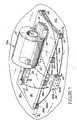
Figure 1 is a perspective view showing an embodiment of the invention, together with certain components of an MR imaging system. -
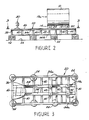
Figure 2 is an elevational side view showing the embodiment ofFigure 1 together with a vibration generator and vibration sensors. -
Figure 3 is an overhead view taken along lines 3-3 ofFigure 2 , with only a portion of the top mounting plate thereof being shown. -
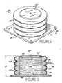
Figure 4 is a perspective view showing a vibration isolation element for the embodiment ofFigure 1 . -
Figure 5 is a sectional view taken along lines 5-5 ofFigure 4 . - Referring to
Figure 1 , there is shown acryostat 10, of a type which is commonly used in connection with MR high field imaging systems. As is well known by those of skill in the art, a main magnet (not shown) is positioned around abore 12 and is contained or enclosed within the cryostat. The cryostat maintains the main magnet at an extremely low temperature. Thus, the main magnet is in a superconductive, state, to produce a strong, static B0 magnetic field as required for MR imaging. The cryostat is provided withmetal legs 14 to support thecryostat 10 and main magnet on a horizontal surface. As is further well known,cryostat 10 also contains gradient coils (not shown) for generating respective X-, Y-, and Z-gradient fields within thebore 12, as are required for MR imaging. The gradient fields are respectively oriented relative to X-, Y-, and Z-coordinate axes, wherein the Z-axis is typically aligned along the axis of the bore, in parallel relationship with the B0 magnetic field. An RF coil (not shown) is positioned within the gradient coils to transmit and/or receive RF signals inbore 12, as are required for MR imaging. -
Figure 1 further shows a patient couch or support 16 proximate to one end ofcryostat 10, and apedestal 18 proximate to the opposing end thereof. The patient support 16 is used to move a patient reclining thereon (not shown) into and out of thebore 12.Pedestal 18 is employed to support other MR system components (not shown) which are associated withcryostat 10. - As stated above, MR system components contained in
cryostat 10, and in particular the gradient coils thereof, can produce significant mechanical vibrations. These vibrations, depicted inFigure 1 by the arrow V1, may be transmitted through thecryostat legs 14 to a floor or other horizontal support surface which is in direct contact withcryostat 10. As stated further, if the cryostat is located in a hospital or other health care site, the vibrations V1 may be transferred through the floor to other building structure, and become very disturbing to patients and others. - At the same time, vibrations present in the site environment, such as may be produced by mechanical equipment and the like, could be transferred to the
cryostat 10 through the supporting floor. Such vibrations, represented inFigure 1 by the arrow V2, may adversely affect MR images produced within thebore 12 ofcryostat 10, as likewise stated above. Accordingly, ifcryostat 10 is supported for operation by a floor or otherhorizontal support surface 22, it may be very desirable to place a barrier therebetween which will prevent transmission of mechanical vibrations in both directions, that is, fromcryostat 10 or other MR system components to the surrounding building structure, as well as from the building structure to the MR system components. - Referring further to
Figure 1 , there is shown an effective vibration barrier provided by mountingcryostat 10, patient support 16 andpedestal 18, as well as other components of the MR system associated therewith (not shown) on aplatform 20. Hereinafter, the cryostat, patient support, pedestal and associated MR components are collectively referred to asMR imaging system 10a.Platform 20 is provided with a top mountingplate 46, or load bearing surface, which is large enough to accomodate respective components ofMR system 10a. As described hereinafter in further detail,platform 20 is constructed to be very stiff or rigid, in order to resist vibrations. Also,platform 20 is provided with substantial mass, namely a mass which is approximately equal to or greater than the combined mass of the components ofMR system 10a which are respectively supported onplatform 20. A number of commonly used MR imaging systems have a mass on the order of 10,000 pounds or more. Thus, the combined mass ofplatform 20 andMR system 10a, which is on the order of 20,000 pounds or more, will effectively suppress mechanical vibrations in accordance with the well known relationship F=ma. In such relationship F represents force, m represents mass, and a represents acceleration, which is a measure of vibration. Such relationship indicates that the combined mass of the platform and MR system will remain immovable, and therefore will not transmit vibrations, unless a very substantial force is applied thereto. -
Figure 1 showsplatform 20 andMR imaging system 10a supported onhorizontal support surface 22 by means ofvibration isolation elements 24. In one useful embodiment, eightisolation elements 24 are used, wherein four elements are spaced along each side of theplatform 20. Each of theisolation elements 24, which are described hereinafter in further detail, comprises an air-tight chamber or enclosure for sealably enclosing a quantity of air under pressure. Each isolation element has a cylindrical side wall, formed of resilient material, and provides both vertical and lateral stability. That is, eachisolation element 24 will act to dampen, and to thus oppose transmission of, mechanical vibrations having components of motion which are oriented to be in both vertical and horizontal planes. One useful type ofisolation element 24 is sold under the registered trademark STABL-LEVL (SLM series) by Barry Controls, a unit of Applied Power Inc. However, the invention is by no means limited thereto. - As an additional feature, the height of each
isolation element 24 is related to the pressure of the air enclosed therein. Thus, theisolation element 24a shown inFigure 1 has a height h1 , when the air pressure therein is p1 . It will be seen that by judiciously selecting a specific air pressure level for each of theisolation elements 24, to correpondingly select the heights thereof, theisolation elements 24 can collectively act to supportplatform 20 abovesurface 22 in an orientation which is substantially horizontal, even ifsurface 22 is not at a true horizontal position. Such horizontal orientation of the platform will significantly enhance operation of theMR imaging system 10a. - To maintain each of the
isolation elements 24 at their respective specified air pressure levels, apressure regulator 26, of conventional design, is coupled to each isolation element through acorresponding air line 26a.Regulator 26 receives air, at shop pressure or the like, through aline 28.Regulator 26 is further provided with a number of pressure adjustment elements 26b, each corresponding to one of theisolation elements 24. Each adjustment element 26b is used to set the air pressure which is supplied to thecorresponding isolation element 24 to the specified level thereof. - Referring to
Figure 2 , there is shown anelectrodynamic shaker 30 positioned onplatform 20, in spaced-apart relationship withMR system 10a.Shaker 30 comprises a conventional device of a type which is operable to generate mechanical vibrations of selected variable amplitudes and frequencies. As described above, the combined action ofplatform 20 andisolation elements 24 effectively isolatesMR system 10a from vibrations which are present in asurface 22 or in other adjacent structure of the environment in which the MR system resides. However, the vibrations produced byshaker 30 are readily transmitted toMR system 10a through thestiff platform 20. Thus, by means ofplatform 20,isolation elements 24, andshaker 30, controlled vibratory motion may be applied toMR system 10a, in order to determine the effects of the vibrations on MR imaging. - In accordance therewith,
Figure 2 further showsaccelerometers 32 joined to two of thelegs 14 of the MR system. For some vibrational patterns, accelerometers are alternatively attached to all four of the legs. Theaccelerometers 32 provide data which varies in corresponding relationship with the vibrations applied toMR system 10a. Moreover, the accelerometer data can be correlated with degradations observed in MR images produced byMR system 10a, as vibratory motion of varying amplitude and frequency is controllably applied thereto byshaker 30. For example, a transfer function may be developed by mapping accelerometer response data to corresponding values of a selected MR parameter which is associated with the production of MR images, and which provides a measure of image artifacts or other degradation. - It will be understood that the acquisition of accelerometer data, by means of
shaker 30 andaccelerometers 32 as described above, can be very useful in preparing a site for a particular MR imaging system. In one embodiment, the MR system is initially set up directly upon the floor or other horizontal surface intended to carry the weight of the system. In such embodiment, theaccelerometers 32 remain attached to the MR system. Accordingly, the outputs of the accelerometers will provide an indication of vibrational energy present at the site which is being transferred to the MR system. By monitoring such accelerometer outputs, and by comparing them with the accelerometer output data previously acquired in conjunction withshaker 30, persons setting up the MR system may readily determine whether images produced by the MR system will be adversely affected by the site vibrations. If not, no further action is required in regard thereto. Otherwise, corrective measures may be taken. For example, acoustic baffles or shielding could be placed around a machine, located close to the MR site, which was identified as a principal source of the vibrations. Alternatively, if comparatively simple measures are not available to prevent the vibrations from reaching the MR system, the system could be mounted on the vibrationbarrier comprising platform 20 andisolation elements 24, as described above. - Referring to
Figures 2 and 3 together, there is shownplatform 20 comprising two upperside frame members 34a, in parallel relationship with each other, which extend between twoend frame members 36 and are firmly joined thereto. In like manner there is shown two lower side frame members 34b, in parallel relationship with each other, which also extend betweenend frame members 36 and are firmly joined thereto. To provide further rigidity toplatform 20,longitudinal beams 38 are provided to likewise extend betweenend frame members 36, in parallel spaced-apart relationship withside frame members 34a.Lateral stiffeners 40 are positioned at intervals alongside frame members 34a and 34b, in parallel relationship withend frame members 36, and are firmly joined to each of theside frame members 34a and 34b andlongitudinal beams 38.Magnet crossbeams 32, positioned between side frame members 34 in parallel relationship with one another, receive the weight ofMR system 10a and distribute the weight toother platform 20 components. Twomagnet mounting plates 44 are placed on eachmagnet crossbeam 42, and are respectively positioned to receive the fourlegs 14 ofMR system 10a. Each magnet mounting plate is provided with abolt hole 44a for use in securely bolting thelegs 14 to thecrossbeams 42. - While only a portion is shown in
Figure 3 , thetop mounting plate 46 extends across the top ofplatform 20, over an area defined by the joinedside frame members 34a andend frame members 36. Usefully, such area is on the order of 8 feet by 20 feet.End frame members 36 andlateral stiffeners 40 respectively comprise channels which extend upwardly fromside frame members 34a, as viewed inFigure 2 . Top mountingplate 46 is firmly joined thereto. - Referring to
Figures 4 and 5 together, there is shown anisolation element 24 generally comprising ametal base plate 48 and acylindrical side wall 50.Side wall 50, as well as atop wall member 52 joined thereto as an integral structure, are formed of the compliant material, as stated above.Side wall 50, to wallmember 52 andbase plate 48 together form an air-tight enclosure 54, which is disposed to retain a quantity ofair 56 under pressure. Air entersenclosure 54 from anair line 26a, as described above, through avalve stem 58. The air pressure level withinenclosure 54 is maintained byair pressure regulator 26, as likewise described above. - Referring further to
Figures 4 and 5 , there is shown a steelload bearing plate 60 embedded intop wall member 52.Load bearing plate 60 is disposed to contact the underside ofplatform 20, to carry a portion of the weight thereof. The height h ofisolation element 24, measured frombase plate 48 to the upper side ofload bearing plate 60, may be adjusted by varying the air pressure withinenclosure 54, as described above. -
Figures 4 and 5 further show sidewall 50 formed to comprise a number ofannular ridges 50a, which are in a vertically stacked relationship. Theridges 50a enhance the vertical and lateral stability of anisolation element 24, so that the isolation element is very effective in preventing transmission of vibrations betweenbase plate 48 andload bearing plate 60.
Claims (8)
- A vibration-isolated MR system for use on a substantially horizontal support surface, said system comprising:an MR imaging system (10a), disposed ona rigid platform (20) having a mass which is approximately equal to or greater than the mass of said MR imaging system;a number of vibration isolation elements (24) for supporting said platform and said MR imaging system upon said horizontal support surface, each of said vibration isolation elements comprising an enclosure for air under pressure which is disposed to dampen vibrations applied thereto; anda pressure regulator (26) coupled to respective vibration isolation elements to maintain specified air pressure levels therein whereby vibrations between said MR imaging system and said support surface are dampened and MR image degradation is minimized.
- The system of claim 1 wherein said platform (20) is provided with a bearing surface sized to receive said MR imaging system.
- The system of claim 1 wherein said pressure regulator (26) is disposed to adjust the air pressure levels in each of said isolation elements to maintain said platform in a horizontal plane, to a specified level of precision.
- The system of claim 1 wherein each of said vibration isolation elements (24) is provided with a side wall member formed of resilient material and with an upper load bearing plate disposed to engage said platform, the bearing plate of a given isolation element being positioned at a height above said horizontal support surface which is determined by the air pressure within said given isolation element.
- The system of claim 1 wherein said MR vibration isolation system further comprises a vibration generator (30) adapted for placement on said platform to apply mechanical vibrations of selected amplitudes and frequencies to said MR imaging system; and a number of vibration sensors (32) selectively joined to said MR imaging system to determine effects of said applied vibrations on the operation of said MR imaging system.
- A method for providing vibration isolation between an MR imaging system (10a) and an associated horizontal support surface (22), containing the steps of:mounting said MR imaging system on a specified vibration barrier comprising a stiff platform (20) of a mass which is approximately equal to or greater than the mass of said MR imaging system and a number of vibration isolation elements (24) positioned to support said platform (20) on said horizontal support surface (22), said platform (20) being adapted to carry the weight of said MR imaging system (10a), and each of said isolation elements (24) comprising an enclosure for air under pressure which is disposed to dampen vibrations applied thereto; andmaintaining a specified air pressure level in each of said isolation elements (24), as required to dampen vibrations and minimize degradation of MR images.
- The method of claim 6 wherein said method comprises the further step of controllably applying vibrations of varying amplitudes and frequencies to said MR imaging system (10a) through said platform (20).
- The method of claim 6 wherein said specified air pressure level is maintained in each of said isolation elements (24) by means of a pressure regulator (26) coupled thereto.
Applications Claiming Priority (2)
| Application Number | Priority Date | Filing Date | Title |
|---|---|---|---|
| US394853 | 1999-09-13 | ||
| US09/394,853 US6375147B1 (en) | 1999-09-13 | 1999-09-13 | Vibration isolation apparatus for MR imaging system |
Publications (3)
| Publication Number | Publication Date |
|---|---|
| EP1085336A2 EP1085336A2 (en) | 2001-03-21 |
| EP1085336A3 EP1085336A3 (en) | 2003-03-19 |
| EP1085336B1 true EP1085336B1 (en) | 2008-09-24 |
Family
ID=23560665
Family Applications (1)
| Application Number | Title | Priority Date | Filing Date |
|---|---|---|---|
| EP00307925A Expired - Lifetime EP1085336B1 (en) | 1999-09-13 | 2000-09-13 | Vibration isolation for an mr imaging system |
Country Status (4)
| Country | Link |
|---|---|
| US (1) | US6375147B1 (en) |
| EP (1) | EP1085336B1 (en) |
| JP (1) | JP4785233B2 (en) |
| DE (1) | DE60040323D1 (en) |
Families Citing this family (24)
| Publication number | Priority date | Publication date | Assignee | Title |
|---|---|---|---|---|
| US6375147B1 (en) * | 1999-09-13 | 2002-04-23 | General Electric Company | Vibration isolation apparatus for MR imaging system |
| US7196519B2 (en) * | 2000-07-28 | 2007-03-27 | Fonar Corporation | Stand-up vertical field MRI apparatus |
| DE10048340C2 (en) * | 2000-09-29 | 2002-11-14 | Siemens Ag | magnetic resonance apparatus |
| WO2002052292A1 (en) * | 2000-12-22 | 2002-07-04 | Koninklijke Philips Electronics N.V. | Medical examination apparatus provided with at least one magnet and noise-absorbing material |
| US7345559B2 (en) * | 2001-09-13 | 2008-03-18 | General Electric Company | High field open MRI magnet isolation system and method |
| DE10148619B4 (en) * | 2001-10-02 | 2006-04-27 | Siemens Ag | magnetic resonance apparatus |
| JP2005531384A (en) * | 2002-07-04 | 2005-10-20 | コーニンクレッカ フィリップス エレクトロニクス エヌ ヴィ | MRI system having a conductive member having a damping effect on vibration |
| US20050087669A1 (en) * | 2002-08-14 | 2005-04-28 | Jen-Shou Tseng | Supporting structure for platform in scanner |
| US6791325B1 (en) | 2003-05-28 | 2004-09-14 | Ge Medical Systems Global Technology Company, Llc | Impedance mismatch apparatus and system for isolation of an MR imaging system |
| US7805084B2 (en) | 2004-05-20 | 2010-09-28 | Finisar Corporation | Dual stage modular optical devices |
| US7438696B2 (en) * | 2005-05-04 | 2008-10-21 | Netmedia Services, Inc. | Physical therapy platform assembly |
| JP4878174B2 (en) * | 2006-02-24 | 2012-02-15 | 株式会社日立製作所 | Magnetic resonance imaging system |
| DE202006020781U1 (en) * | 2006-05-04 | 2010-06-10 | Tomovation Gmbh | Measuring device for detecting interference fields at an installation location of a magnetic resonance tomography system |
| US20090189611A1 (en) * | 2006-08-22 | 2009-07-30 | Koninklijke Philips Electronics N. V. | Magnetic resonance imaging system with reduced unintentional mechanical movements |
| US8170225B2 (en) * | 2007-02-14 | 2012-05-01 | Integrated Dynamics Engineering Gmbh | Method for adapting a vibration isolation system |
| DE102009009562A1 (en) * | 2009-02-19 | 2010-09-09 | Integrated Dynamics Engineering Gmbh | Combined motion sensor for use in feedback control systems for vibration isolation |
| DE102011083837B4 (en) | 2011-09-30 | 2015-10-29 | Siemens Aktiengesellschaft | Medical imaging device with a pressure chamber for damping vibrations |
| GB2497342B (en) * | 2011-12-08 | 2014-06-18 | Siemens Plc | Vibration isolation for superconducting magnets |
| EP2759735B1 (en) * | 2013-01-29 | 2016-06-15 | Integrated Dynamics Engineering GmbH | Stationary vibration insulation system and method for regulating a vibration insulation system |
| US20160161044A1 (en) * | 2014-12-09 | 2016-06-09 | Caterpillar Inc. | Base for power source components |
| US9788446B1 (en) * | 2015-03-27 | 2017-10-10 | Paul H. Townsend | Mobile vibration isolation device |
| KR102537846B1 (en) * | 2018-04-26 | 2023-06-05 | 삼성디스플레이 주식회사 | Monitoring system of vibration isolated foundation |
| CN108631496B (en) * | 2018-05-15 | 2021-08-20 | 江苏金泰堡机械制造有限公司 | Motor vibration damping base with multiple vibration structures |
| US11859759B2 (en) * | 2018-09-05 | 2024-01-02 | Synaptive Medical Inc. | Support stand for magnetic resonance imaging scanner |
Citations (1)
| Publication number | Priority date | Publication date | Assignee | Title |
|---|---|---|---|---|
| EP0767320A2 (en) * | 1995-10-04 | 1997-04-09 | Ebara Corporation | Vibration damping apparatus |
Family Cites Families (21)
| Publication number | Priority date | Publication date | Assignee | Title |
|---|---|---|---|---|
| US3589655A (en) * | 1969-03-10 | 1971-06-29 | Consolidated Kinetics Corp | Apparatus for isolating vibrations |
| US3582027A (en) * | 1969-03-10 | 1971-06-01 | Consolidated Kinetics Corp | Apparatus for isolating vibrations |
| US3836134A (en) * | 1973-03-19 | 1974-09-17 | Wright Barry Corp | Pneumatic isolator |
| FR2541551A1 (en) * | 1983-02-21 | 1984-08-24 | Drusch & Cie | DEVICE FOR HOLDING AND FIXING COILS FOR REALIZING A CONSTANT AND HOMOGENEOUS MAGNETIC FIELD |
| JPS59172403U (en) * | 1983-04-30 | 1984-11-17 | 株式会社東芝 | Diagnostic nuclear magnetic resonance apparatus |
| JPS63199938A (en) * | 1987-02-12 | 1988-08-18 | Bridgestone Corp | Vibration-proof supporting device |
| US5016638A (en) * | 1989-03-01 | 1991-05-21 | Hsieh Chi H | Vibration control in NMR magnet structures |
| US5282601A (en) * | 1991-06-20 | 1994-02-01 | General Electric Company | Isolation system for medical imaging equipment |
| JP3107443B2 (en) * | 1992-02-21 | 2000-11-06 | 倉敷化工株式会社 | Anti-vibration device |
| JPH06117487A (en) * | 1992-10-05 | 1994-04-26 | Hakko Denki Kk | Vibration control device for machinery |
| US5573220A (en) * | 1995-05-30 | 1996-11-12 | Unisorb Inc. | Adjustable vibration absorbing machinery foundation mount and method for tuning the same |
| US5812420A (en) * | 1995-09-05 | 1998-09-22 | Nikon Corporation | Vibration-preventive apparatus and exposure apparatus |
| JP3337906B2 (en) * | 1996-04-02 | 2002-10-28 | キヤノン株式会社 | Pneumatic vibration insulation removing apparatus, projection exposure apparatus, and device manufacturing method using the same |
| KR980006398A (en) * | 1996-06-21 | 1998-03-30 | 마에다 시게루 | Vibration damping device |
| JPH1089403A (en) * | 1996-09-10 | 1998-04-07 | Nikon Corp | Vibration control device |
| JPH10112433A (en) * | 1996-10-04 | 1998-04-28 | Nikon Corp | Seismic base isolation device and exposure device |
| JP3619623B2 (en) * | 1996-10-17 | 2005-02-09 | 株式会社東芝 | Magnetic resonance imaging apparatus and sound insulation method for magnetic resonance imaging |
| US5996960A (en) * | 1998-05-08 | 1999-12-07 | Hewlett-Packard Company | Vibration isolation platform |
| US6231442B1 (en) * | 1998-07-08 | 2001-05-15 | Battle Born Gaming | Video slot machine with multi-choice second bonus |
| US6169404B1 (en) * | 1998-12-18 | 2001-01-02 | General Electric Company | Vibration cancellation for C-shaped superconducting magnet |
| US6375147B1 (en) * | 1999-09-13 | 2002-04-23 | General Electric Company | Vibration isolation apparatus for MR imaging system |
-
1999
- 1999-09-13 US US09/394,853 patent/US6375147B1/en not_active Expired - Fee Related
-
2000
- 2000-09-12 JP JP2000275750A patent/JP4785233B2/en not_active Expired - Fee Related
- 2000-09-13 DE DE60040323T patent/DE60040323D1/en not_active Expired - Lifetime
- 2000-09-13 EP EP00307925A patent/EP1085336B1/en not_active Expired - Lifetime
Patent Citations (1)
| Publication number | Priority date | Publication date | Assignee | Title |
|---|---|---|---|---|
| EP0767320A2 (en) * | 1995-10-04 | 1997-04-09 | Ebara Corporation | Vibration damping apparatus |
Also Published As
| Publication number | Publication date |
|---|---|
| EP1085336A2 (en) | 2001-03-21 |
| DE60040323D1 (en) | 2008-11-06 |
| EP1085336A3 (en) | 2003-03-19 |
| US6375147B1 (en) | 2002-04-23 |
| JP4785233B2 (en) | 2011-10-05 |
| JP2001145611A (en) | 2001-05-29 |
Similar Documents
| Publication | Publication Date | Title |
|---|---|---|
| EP1085336B1 (en) | Vibration isolation for an mr imaging system | |
| US6774633B2 (en) | High-field open MRI magnet isolation system and method | |
| US6933722B2 (en) | Magnetic resonance imaging device and gradient magnetic field coil used for it | |
| US7372271B2 (en) | Main magnet perforated eddy current shield for a magnetic resonance imaging device | |
| EP1348136B1 (en) | Mri apparatus with a piezo actuator in a non-rigid suspension of the gradient coil carrier | |
| EP1193507A2 (en) | Low noise MRI scanner | |
| US6894498B2 (en) | Active vibration compensation for MRI gradient coil support to reduce acoustic noise in MRI scanners | |
| US20090209842A1 (en) | Mri gradient coil assembly with reduced acoustic noise | |
| WO2005115239A1 (en) | Magnetic resonance imaging device | |
| EP1826582A2 (en) | MRI apparatus involving damping of vibrations | |
| JP2002315736A (en) | Magnetic resonance imaging | |
| US7253623B2 (en) | Magnetic resonance imaging apparatus and magnetic field forming apparatus | |
| US20020041186A1 (en) | Magnetic resonance apparatus | |
| US6822446B2 (en) | MRI magnet vibration induced field instability simulator | |
| US20070182516A1 (en) | Magnetic resonance imaging device with an active shielding device | |
| US20060076954A1 (en) | Method for compensating for a magnetic field disturbance affecting a magnetic resonance device, and a magnetic resonance device | |
| US20060006866A1 (en) | Mri system with a conductive member having a damping effect for vibrations | |
| US6636136B1 (en) | Mechanical stabilizer-tuned damper for high field open magnet | |
| US7224166B2 (en) | MRI system having a gradient magnet system with a gyroscope | |
| US20090189611A1 (en) | Magnetic resonance imaging system with reduced unintentional mechanical movements | |
| Rodrigue | Preliminary Investigation into the Vibration Characteristics and Isolation Requirements of a Prototype MRI Scanner | |
| Reid | Vibration control: the rigid equipment support platform | |
| Sharma et al. | Investigation of passive vibration damping methods for the Advanced Photon Source storage ring girders. | |
| JPH06280930A (en) | Active type vibration resisting device |
Legal Events
| Date | Code | Title | Description |
|---|---|---|---|
| PUAI | Public reference made under article 153(3) epc to a published international application that has entered the european phase |
Free format text: ORIGINAL CODE: 0009012 |
|
| AK | Designated contracting states |
Kind code of ref document: A2 Designated state(s): AT BE CH CY DE DK ES FI FR GB GR IE IT LI LU MC NL PT SE |
|
| AX | Request for extension of the european patent |
Free format text: AL;LT;LV;MK;RO;SI |
|
| PUAL | Search report despatched |
Free format text: ORIGINAL CODE: 0009013 |
|
| AK | Designated contracting states |
Kind code of ref document: A3 Designated state(s): AT BE CH CY DE DK ES FI FR GB GR IE IT LI LU MC NL PT SE |
|
| AX | Request for extension of the european patent |
Extension state: AL LT LV MK RO SI |
|
| RIC1 | Information provided on ipc code assigned before grant |
Ipc: 7F 16F 15/023 B Ipc: 7G 01R 33/28 A Ipc: 7G 01R 33/385 B |
|
| 17P | Request for examination filed |
Effective date: 20030919 |
|
| AKX | Designation fees paid |
Designated state(s): DE NL |
|
| 17Q | First examination report despatched |
Effective date: 20041228 |
|
| 17Q | First examination report despatched |
Effective date: 20041228 |
|
| GRAP | Despatch of communication of intention to grant a patent |
Free format text: ORIGINAL CODE: EPIDOSNIGR1 |
|
| RTI1 | Title (correction) |
Free format text: VIBRATION ISOLATION FOR AN MR IMAGING SYSTEM |
|
| GRAS | Grant fee paid |
Free format text: ORIGINAL CODE: EPIDOSNIGR3 |
|
| GRAA | (expected) grant |
Free format text: ORIGINAL CODE: 0009210 |
|
| AK | Designated contracting states |
Kind code of ref document: B1 Designated state(s): DE NL |
|
| REF | Corresponds to: |
Ref document number: 60040323 Country of ref document: DE Date of ref document: 20081106 Kind code of ref document: P |
|
| PLBE | No opposition filed within time limit |
Free format text: ORIGINAL CODE: 0009261 |
|
| STAA | Information on the status of an ep patent application or granted ep patent |
Free format text: STATUS: NO OPPOSITION FILED WITHIN TIME LIMIT |
|
| 26N | No opposition filed |
Effective date: 20090625 |
|
| PGFP | Annual fee paid to national office [announced via postgrant information from national office to epo] |
Ref country code: DE Payment date: 20130927 Year of fee payment: 14 Ref country code: NL Payment date: 20130926 Year of fee payment: 14 |
|
| REG | Reference to a national code |
Ref country code: DE Ref legal event code: R119 Ref document number: 60040323 Country of ref document: DE |
|
| REG | Reference to a national code |
Ref country code: DE Ref legal event code: R119 Ref document number: 60040323 Country of ref document: DE Effective date: 20150401 |
|
| PG25 | Lapsed in a contracting state [announced via postgrant information from national office to epo] |
Ref country code: NL Free format text: LAPSE BECAUSE OF NON-PAYMENT OF DUE FEES Effective date: 20150401 |
|
| PG25 | Lapsed in a contracting state [announced via postgrant information from national office to epo] |
Ref country code: DE Free format text: LAPSE BECAUSE OF NON-PAYMENT OF DUE FEES Effective date: 20150401 |