EP1293670A2 - Compressor head with improved oil retention - Google Patents
Compressor head with improved oil retention Download PDFInfo
- Publication number
- EP1293670A2 EP1293670A2 EP02078468A EP02078468A EP1293670A2 EP 1293670 A2 EP1293670 A2 EP 1293670A2 EP 02078468 A EP02078468 A EP 02078468A EP 02078468 A EP02078468 A EP 02078468A EP 1293670 A2 EP1293670 A2 EP 1293670A2
- Authority
- EP
- European Patent Office
- Prior art keywords
- wall
- fluid
- chamber
- assembly
- discharge
- Prior art date
- Legal status (The legal status is an assumption and is not a legal conclusion. Google has not performed a legal analysis and makes no representation as to the accuracy of the status listed.)
- Granted
Links
- 230000014759 maintenance of location Effects 0.000 title description 15
- 239000012530 fluid Substances 0.000 claims abstract description 105
- 230000006835 compression Effects 0.000 claims abstract description 60
- 238000007906 compression Methods 0.000 claims abstract description 60
- 238000004891 communication Methods 0.000 claims abstract description 20
- 238000005192 partition Methods 0.000 claims abstract description 6
- 235000014676 Phragmites communis Nutrition 0.000 claims description 45
- 238000004378 air conditioning Methods 0.000 claims description 20
- 238000005461 lubrication Methods 0.000 claims description 12
- 230000001105 regulatory effect Effects 0.000 claims description 9
- 230000004888 barrier function Effects 0.000 claims description 7
- 239000003507 refrigerant Substances 0.000 description 13
- 230000008901 benefit Effects 0.000 description 5
- 238000004519 manufacturing process Methods 0.000 description 5
- 230000010349 pulsation Effects 0.000 description 5
- 229910000831 Steel Inorganic materials 0.000 description 4
- 230000000712 assembly Effects 0.000 description 4
- 238000000429 assembly Methods 0.000 description 4
- 239000010959 steel Substances 0.000 description 4
- 244000273256 Phragmites communis Species 0.000 description 3
- XAGFODPZIPBFFR-UHFFFAOYSA-N aluminium Chemical compound [Al] XAGFODPZIPBFFR-UHFFFAOYSA-N 0.000 description 3
- 229910052782 aluminium Inorganic materials 0.000 description 3
- 230000001050 lubricating effect Effects 0.000 description 3
- 239000000463 material Substances 0.000 description 3
- XEEYBQQBJWHFJM-UHFFFAOYSA-N Iron Chemical compound [Fe] XEEYBQQBJWHFJM-UHFFFAOYSA-N 0.000 description 2
- OKTJSMMVPCPJKN-UHFFFAOYSA-N Carbon Chemical compound [C] OKTJSMMVPCPJKN-UHFFFAOYSA-N 0.000 description 1
- -1 but not limited to Substances 0.000 description 1
- 229910052799 carbon Inorganic materials 0.000 description 1
- 239000002131 composite material Substances 0.000 description 1
- 238000001816 cooling Methods 0.000 description 1
- 238000006073 displacement reaction Methods 0.000 description 1
- 230000000694 effects Effects 0.000 description 1
- 230000005484 gravity Effects 0.000 description 1
- 230000006872 improvement Effects 0.000 description 1
- 229910052742 iron Inorganic materials 0.000 description 1
- 230000007246 mechanism Effects 0.000 description 1
- 238000012986 modification Methods 0.000 description 1
- 230000004048 modification Effects 0.000 description 1
- 238000004806 packaging method and process Methods 0.000 description 1
- 230000037361 pathway Effects 0.000 description 1
- 238000011176 pooling Methods 0.000 description 1
- 238000005086 pumping Methods 0.000 description 1
- 238000000926 separation method Methods 0.000 description 1
Images


Classifications
-
- F—MECHANICAL ENGINEERING; LIGHTING; HEATING; WEAPONS; BLASTING
- F04—POSITIVE - DISPLACEMENT MACHINES FOR LIQUIDS; PUMPS FOR LIQUIDS OR ELASTIC FLUIDS
- F04B—POSITIVE-DISPLACEMENT MACHINES FOR LIQUIDS; PUMPS
- F04B27/00—Multi-cylinder pumps specially adapted for elastic fluids and characterised by number or arrangement of cylinders
- F04B27/08—Multi-cylinder pumps specially adapted for elastic fluids and characterised by number or arrangement of cylinders having cylinders coaxial with, or parallel or inclined to, main shaft axis
- F04B27/10—Multi-cylinder pumps specially adapted for elastic fluids and characterised by number or arrangement of cylinders having cylinders coaxial with, or parallel or inclined to, main shaft axis having stationary cylinders
- F04B27/1036—Component parts, details, e.g. sealings, lubrication
- F04B27/109—Lubrication
-
- F—MECHANICAL ENGINEERING; LIGHTING; HEATING; WEAPONS; BLASTING
- F04—POSITIVE - DISPLACEMENT MACHINES FOR LIQUIDS; PUMPS FOR LIQUIDS OR ELASTIC FLUIDS
- F04B—POSITIVE-DISPLACEMENT MACHINES FOR LIQUIDS; PUMPS
- F04B27/00—Multi-cylinder pumps specially adapted for elastic fluids and characterised by number or arrangement of cylinders
- F04B27/08—Multi-cylinder pumps specially adapted for elastic fluids and characterised by number or arrangement of cylinders having cylinders coaxial with, or parallel or inclined to, main shaft axis
- F04B27/10—Multi-cylinder pumps specially adapted for elastic fluids and characterised by number or arrangement of cylinders having cylinders coaxial with, or parallel or inclined to, main shaft axis having stationary cylinders
- F04B27/1036—Component parts, details, e.g. sealings, lubrication
- F04B27/1081—Casings, housings
Definitions
- a head assembly for use in a compressor having a compression chamber for compressing a fluid is disclosed. More specifically, the head assembly includes an improvement for retaining oil in the compressor.
- Vehicle air-conditioning systems include a compressor that compresses and superheats refrigerant.
- the refrigerant exits the compressor and continues first to a condenser and then to an expander. From the expander, the refrigerant enters an evaporator and then returns to the compressor to begin the cycle again.
- the air-conditioning system will include either an accumulator/dehydrator (A/D) or a receiver/dehydrator (R/D).
- A/D accumulator/dehydrator
- R/D receiver/dehydrator
- the compressor is a belt-driven pump that includes at least one compression chamber and a head assembly comprising a manifold housing, an intake port and an exhaust port.
- the manifold housing further defines a suction chamber and a discharge chamber.
- the intake port guides the refrigerant from the evaporator to the suction chamber.
- the suction chamber subsequently guides the refrigerant from the intake port to the compression chamber where it is compressed.
- the compressed refrigerant is received in the discharge chamber and from the discharge chamber the refrigerant is exhausted to the exhaust port.
- the refrigerant is then guided from the exhaust port to the condenser to begin the cycle again.
- Prior art head assemblies experience oil retention problems and difficulty protecting the compressor from wear. Oil retention is crucial for lubricating the working components of the compressor. Retaining oil in the compressor increases the life of the compressor.
- the '314 patent to Kobayashi et al. includes an oil retention housing defining a oil retention chamber wherein the housing is mounted to an outside wall of the compressor.
- the refrigerant and oil exit the discharge chamber to the oil retention chamber and gravity pulls the oil toward a bottom end of the oil retention chamber.
- a supply line connects the oil retention chamber to a lubrication chamber, which stores the oil in the compressor for lubricating the components.
- the oil retention chamber requires additional structure with the existing head assembly and compressor thereby increasing costs and hampering ease of manufacture.
- the oil retention chamber must be located above the compressor, posing packaging issues and the fixed orifice supply line results in performance losses within the air-conditioning system.
- Both the '578 patent to Kayukawa et al. and the '314 patent to Kobayashi et al. include head assemblies wherein the discharge chamber substantially surrounds the suction chamber and is unobstructed in relation to the exhaust port. This configuration limits oil retention within the compressor by not providing a sufficient barrier between the discharge chamber and the exhaust port. Additionally, both the '578 patent to Kayukawa et al. and the '314 patent to Kobayashi et al. require additional structures that complicates manufacture of the head assembly. As a result, there is a need for a head assembly that increases oil retention in the compressor without adding additional, unnecessary structural components or separate structures, resulting in easier manufacturing and a more economical head assembly.
- a head assembly for use in a compressor having oil for lubrication and defining a first compression chamber for compressing a fluid.
- the head assembly includes a manifold housing defining an intake port, an exhaust port and a control valve port.
- the manifold housing comprises an outer wall, a first inner wall and a second inner wall wherein the outer wall and the first inner wall define a suction chamber in fluid communication with the intake port for receiving the fluid from the intake port and guiding the fluid to the first compression chamber.
- the first inner wall and the second inner wall define a discharge chamber for receiving the fluid from the first compression chamber.
- An aperture is formed in the first inner wall for guiding the fluid and the oil from the discharge chamber to the control valve port.
- the second inner wall is internal to the outer wall and the first inner wall and defines an exit chamber for guiding the fluid from the discharge chamber to the exhaust port.
- the exit chamber is in fluid communication with the exhaust port and the second inner wall defines a partition between the aperture and the exhaust port such that the oil pools in the discharge chamber between the first inner wall and the second inner wall thereby retaining the oil in the compressor to lubricate the compressor.
- a compressor assembly for compressing a fluid and having oil for lubrication.
- the compressor includes a compressor housing defining a compression chamber for compressing the fluid.
- a piston is disposed in the compression chamber and is slidably movable within the compression chamber.
- a manifold housing is coupled to the compressor housing and defines an intake port, an exhaust port and a control valve port.
- the manifold housing comprises an outer wall, a first inner wall and a second inner wall.
- the outer wall and the first inner wall define a suction chamber in fluid communication with the intake port for receiving the fluid from the intake port and guiding the fluid to the compression chamber.
- the first inner wall and the second inner wall define a discharge chamber for receiving the fluid from the compression chamber.
- An aperture is formed in the first inner wall for guiding the fluid and the oil from the discharge chamber to the control valve port.
- the second inner wall is internal to the outer wall and the first inner wall and defines an exit chamber for guiding the fluid from the discharge chamber to the exhaust port. Additionally, the exit chamber is in fluid communication with the exhaust port and the second inner wall defines a partition between the aperture and the exhaust port such that the oil pools in the discharge chamber between the first inner wall and the second inner wall thereby retaining the oil in the compressor to lubricate the compressor.
- the advantage of the subject invention described above is the ability of the subject invention to effectively increase oil retention within the compressor without adding unnecessary structure or plugs to the head assembly. More specifically, the advantage of the subject invention is the configuration of the second inner wall wherein the second inner wall provides the barrier between the aperture and the exhaust port. This barrier is critical in pooling the oil in the manifold housing prior to being discharged to the control valve port. Furthermore, the subject invention is easy to manufacture relative to the prior art head assemblies and the subject invention provides additional advantages that will become apparent from the description of the preferred embodiment including higher efficiency and increased performance.
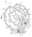
- a head assembly 10 for use in a compressor (or compressor assembly) 12 having a compressor housing 13 and defining a first compression chamber 14 for compressing a fluid is disclosed.
- the subject invention is intended to be used in conjunction with an air-conditioning system 15 that utilizes refrigerant for cooling, however, this is not intended to limit the subject invention.
- Other systems or fluids such as, but not limited to air could also be used in conjunction with the subject invention.
- the head assembly 10 comprises a manifold housing 16 defining an intake port 18, an exhaust port 20 and a control valve port 22.
- the manifold housing 16 includes an outer wall 24, a first inner wall 26 and a second inner wall 28.
- the outer wall 24 and the first inner wall 26 define a suction chamber 30 that is in fluid communication with the intake port 18 for receiving the fluid from the intake port 18 and guiding the fluid to the first compression chamber 14.
- the first inner wall 26 and the second inner wall 28 define a discharge chamber 32 for receiving the fluid from the first compression chamber 14.
- the outer wall 24, the first inner wall 26 and the second inner wall 28 are integrally formed with the manifold housing 16 and the manifold housing 16 is made from die cast aluminum. It is to be understood that the manifold housing 16 is not limited to integrally formed walls or die cast aluminum. The manifold housing 16 may be made from a number of materials including, but not limited to, steel, iron, and so on. Furthermore, the manifold housing 16 is mounted to the compressor 12 by a plurality of through bolts (not shown) positioned within a matching plurality of mounting bores 33 that are circumferentially spaced within the outer wall 24. Any number of attaching devices could be used to mount the manifold housing 16 to the compressor 12 and this is not intended to limit the subject invention.
- An aperture 34 is formed in the first inner wall 26 for guiding the fluid and the oil from the discharge chamber 32 to the control valve port 22.
- the second inner wall 28 is internal to the outer wall 24 and the first inner wall 26.
- the second inner wall 28 defines an exit chamber 36 for guiding the fluid from the discharge chamber 32 to the exhaust port 20.
- the exit chamber 36 is in fluid communication with the exhaust port 20.
- the second inner wall 28 defines a partition 38 between the aperture 34 and the exhaust port 20 such that oil pools in the discharge chamber 32 between the first inner wall 26 and the second inner wall 28 thereby retaining the oil in the compressor 12 to lubricate the compressor 12.
- the oil is entrained in the fluid for lubricating the compressor, which increases the life expectancy of working components within the compressor 12.
- the second inner wall 28 has a continuous outer surface 40, which forces the oil to pool between the first inner wall 26 and the outer surface 40.
- the discharge chamber 32 substantially surrounds the exit chamber 36 in this embodiment. As a result, the oil can pool within the discharge chamber 32 around the outer surface 40 of the second inner wall 28 until the oil spills over the second inner wall 28 into the exit chamber 36.
- a further advantage of the position of the exit chamber 36 with respect to the discharge chamber 32 is the effect on pressure pulsations within the compressor 12. Testing of the compressor 12 with the head assembly 10 has shown that off-order pressure pulsations have been substantially suppressed by utilizing a centrally located exit chamber 36. Gas pulsations circulating through the compressor are forced from the discharge chamber 32 to the exit chamber 36. As a result, off-order pressure pulsations are suppressed, leaving behind primary pumping order pressure pulsations (7 th order, 14 th order and 21 st order).
- the head assembly 10 further includes an exhaust housing 42 integrally formed with the manifold housing 16.
- the exhaust housing 42 further defines the exhaust port 20.
- the exhaust housing 42 also defines a suction barrier 44 between the exhaust port 20 and the suction chamber 30 to prevent fluid in the exhaust port 20 from being transferred to the suction chamber 30.
- the exhaust housing 42 defines a discharge barrier 46 between the exhaust port 20 and the discharge chamber 32 to prevent oil in the discharge chamber 32 from escaping from the compressor 12 through the exhaust port 20.
- the exhaust housing 42 further includes a first channel wall 48 having an internal surface 50 and a first end 52 defining a first channel 54 and a second channel wall 56 defining a second channel 58.
- the first channel 54 is in fluid communication with the exit chamber 36 and the second channel 58 is in fluid communication with the first channel 54 such that the fluid travels from the exit chamber 36 to the first channel 54 then to the second channel 58 and finally is exhausted from the second channel 58.
- the internal surface 50 of the first channel wall 48 includes female threads 60 near the first end 52.
- the female threads 60 are intended to engage a high pressure relief valve 62 having male threads 64.
- the high pressure relief valve 62 provides pressure relief in the compressor 12.
- the high pressure relief valve 62 releases fluid from the air-conditioning system 15 when pressure within the system 15 reaches a predetermined value.
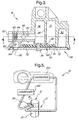
- the subject invention further includes a valve plate 66 positioned between the manifold housing 16 and the first compression chamber 14.
- the valve plate 66 and the second inner wall 28 define a trap 68 for separating debris from the fluid and preventing the debris from entering said exhaust port 20. Trapping the debris that is either ingested or produced by the compressor 12 is important for preventing the restriction of flow of the fluid through the remaining components of the air-conditioning system 15. Specifically, the debris that exits the compressor 12 that is larger than 0.5 mm can result in a debilitated air-conditioning system 15.
- the discharge reed 70 engages the valve plate 66 and is positioned between the valve plate 66 and the manifold housing 16.
- the discharge reed 70 is movable between a discharge position 72 (as shown in dashed lines) and a closed position 74 such that the fluid enters the discharge chamber 32 from the first compression chamber 14 when the discharge reed 70 is in the discharge position 72.
- the discharge reed 70 prevents the fluid from re-entering the first compression chamber 14 from the discharge chamber 32 when in the closed position 74.
- the discharge reed 70 is held in place by a discharge reed retainer 76 that is secured to the valve plate 66.
- the discharge reed 70 is positioned between the discharge reed retainer 76 and the valve plate 66.
- a fastener 78 is used to attach the discharge reed retainer 76 to the valve plate 66.
- the fastener 78 is a rivet, however, it is to be understood that any fastening device may be used, such as, but not limited to, a screw, a bolt and nut assembly, a weld, a clip and so on.
- the head assembly 10 further includes a suction reed 80.
- the suction reed 80 engages the valve plate 66 for regulating the movement of the fluid from the suction chamber 30 to the first compression chamber 14.
- the suction reed 80 is movable between a suction position 82 and a shutoff position 84 such that the fluid enters the first compression chamber 14 when the suction reed 80 is in the suction position 82 (as shown in dashed lines) and the suction reed 80 prevents the fluid from re-entering the suction chamber 30 from the first compression chamber 14 when in the shutoff position 84.
- Both the discharge reed 70 and the suction reed 80 are made from steel, more specifically, a 1% carbon flapper valve steel to add flexibility to the reeds 70,80.
- the reed material is not limited to steel and could include a variety of materials including a composite material, aluminum and so on.
- the discharge reed retainer 76 and the second inner wall 28 define a debris trap 86 for separating the debris from the fluid and preventing the debris from entering the exhaust port 20.
- the debris trap 86 is to be distinguished from the trap 68 in that the debris trap 86 is defined by the discharge reed retainer 76 and the second inner wall 28 and the trap 68 is defined by the valve plate 66 and the second inner wall 28.
- the debris trap 86 is sized to prevent the debris greater than 0.5 mm in size from entering the exit chamber 36.
- the compressor 12 includes a piston 88 slidably moveable within the first compression chamber 14 for compressing the fluid in the compressor 12.
- the compressor 12 further defines a second compression chamber 90 spaced apart from the first compression chamber 14 for receiving the fluid from the suction chamber 30 in the same manner as the first compression chamber 14.
- a cylinder wall 92 separates the first compression chamber 14 and the second compression chamber 90 and a second piston 94 is positioned in the second compression chamber 90 and is slidably moveable therein for compressing the fluid in the compressor 12.
- the compressor 12 includes seven pistons and seven compression chambers, however, for simplicity, only the first and the second pistons 88,94 and compression chambers 14,90 are discussed. The number of pistons and compression chambers is not intended to limit the subject invention.
- the compressor 12 also defines a lubrication chamber 96 for storing the oil in the compressor 12.
- the lubrication chamber 96 sometimes referred to as a crankcase, is used to supply the oil to the pistons 88,94 to minimize friction along the cylinder wall 92.
- the oil that is stored in the lubrication chamber 96 is also used to lubricate other moving parts in the compressor. It is a feature of the subject invention to increase the retention of the oil in the compressor 12 and more specifically, to retain the oil in the lubrication chamber 96.
- a control valve plug 98 is disposed within the control valve port 22 for regulating the flow of the fluid and the oil from the discharge chamber 32 to the lubrication chamber 96, thereby, regulating pressure within the compressor 12.
- the control valve plug 98 includes a control valve 99 that is in fluid communication with the discharge chamber 32 through the aperture 34 formed in the first inner wall 26 and as a result, the control valve 99 controls the movement of fluid through the aperture 34.
- the control valve 99 is opened and closed based on the operation of the air-conditioning system 15.
- the control valve plug 98 shown in Figure 4 is of the pneumatic type. The opening and closing of the control valve 99 is regulated by incoming suction pressure. A control valve set point is established at the factory. The control valve 99 opens and closes relative to the set point. When the incoming suction pressure is higher than the set point, the control valve 99 is closed and the compressor 12 is at full stroke or full displacement.
- the control valve plug 98 could also be of the electronic type. In such a case, an electrical signal is used to actuate the control valve 99.
- the control valve 99 When the control valve 99 is closed, the only pathway for the fluid that enters the discharge chamber is into the exit chamber 36 and then through the first and second channels 54,58 to the air-conditioning system 15. During this fluid movement, the oil that is entrained in the fluid is pooled in the discharge chamber 32 near the aperture 34.
- the control valve 99 When the control valve 99 is opened, the fluid in the discharge chamber 32 and the oil that has pooled near the aperture 34 is drawn into a fluid line 101 that connects the control valve port 22 to the lubrication chamber 96.
- the fluid line 101 could be an additional line, but in the subject invention, the fluid line 101 is an existing line connected to the control valve 99 for regulating pressure in the compressor 12.
- the air-conditioning system 15 of the preferred embodiment includes an evaporator 100 for transferring heat and a condenser 102 in fluid communication with the evaporator 100.
- a conventional air-conditioning system may include additional components, however, only the general configuration as shown in Figure 5 will be discussed.
- the lines connecting the evaporator 100, condenser 102 and compressor 12 are for schematic representation only and are not intended to represent structure.
- the condenser 102 receives the fluid from the compressor 12. From the condenser 102, the fluid travels to the evaporator 100.
- the compressor 12 works in concert with the evaporator 100 and the condenser 102 as part of the air-conditioning system 15 such that the fluid enters the intake port 18 from the air-conditioning system 15 and exits the exhaust port 20 to be recirculated in the air-conditioning system 15.
- the pistons 88,94 are reciprocated or slidably moved within their respective compression chambers 14,90.
- the suction reed 80 is moved to the suction position 82 as the piston 88 moves from a top dead center position 104 toward the lubrication chamber 96 thereby drawing the fluid into the respective compression chamber 14,90.
- the discharge reed 70 is moved to the discharge position 72 thereby forcing the fluid into the discharge chamber 32.
- all seven compression chambers include both suction reeds 80 and discharge reeds 70 to control the movement of the fluid within the compressor 12.
Landscapes
- Engineering & Computer Science (AREA)
- Mechanical Engineering (AREA)
- General Engineering & Computer Science (AREA)
- Compressor (AREA)
Abstract
Description
Claims (33)
- A head assembly (10) for use in a compressor (12) having oil for lubrication and defining a first compression chamber (14) for compressing a fluid, said assembly (10) comprising a manifold housing (16) defining an intake port (18), an intake port (20) and a control valve port (22) and having an outer wall (24), a first inner wall (26) and a second inner wall (28), said outer wall (24) and said first inner wall (26) defining a suction chamber (30) in fluid communication with said intake port (18) for receiving the fluid from said intake port (18) and guiding the fluid to the first compression chamber (14), said first inner wall (26) and said second inner wall (28) defining a discharge chamber (32) for receiving the fluid from the first compression chamber (14), an aperture (34) formed in said first inner wall (26) for guiding the fluid and the oil from said discharge chamber (32) to said control valve port (22), said assembly (10) characterized by said second inner wall (28) being internal to said outer wall (24) and said first inner wall (26) and defining an exit chamber (36) for guiding the fluid from said discharge chamber (32) to said intake port (20), said exit chamber (36) being in fluid communication with said intake port (20) and said second inner wall (28) defining a partition (38) between said aperture (34) and said intake port (20) such that the oil pools in said discharge chamber (32) between said first inner wall (26) and said second inner wall (28) thereby retaining the oil in the compressor (12) to lubricate the compressor (12).
- The assembly (10) as set forth in claim 1 wherein said second inner wall (28) further includes an outer surface (40), said outer surface (40) being continuous for allowing the oil to pool between said first inner wall (26) and said outer surface (40).
- The assembly (10) as set forth in claim 2 further including an exhaust housing (42) integrally formed with said manifold housing (16), said exhaust housing (42) further defining said intake port (20).
- The assembly (10) as set forth in claim 3 wherein said exhaust housing (42) defines a suction barrier (44) between said intake port (20) and said suction chamber (30) to prevent fluid in said suction chamber (30) from being transferred to said intake port (20).
- The assembly (10) as set forth in claim 3 wherein said exhaust housing (42) defines a discharge barrier (46) between said intake port (20) and said discharge chamber (32) to prevent oil in said discharge chamber (32) from escaping from the compressor (12) through said intake port (20).
- The assembly (10) as set forth in claim 3 wherein said exhaust housing (42) further includes a first channel wall (48) having an internal surface (50) and a first end (52) defining a first channel (54) and a second channel wall (56) defining a second channel (58), said first channel (54) being in fluid communication with said exit chamber (36) and said second channel (58) being in fluid communication with said first channel.
- The assembly (10) as set forth in claim 6 wherein said internal surface (50) of said first channel wall (48) further includes female threads (60) near said first end (52).
- The assembly (10) as set forth in claim 7 further including a high pressure relief valve (62) having male threads (64), said male threads (64) engaging said female threads (60) of said first channel (54) for providing pressure relief in the compressor (12).
- The assembly (10) as set forth in claim 1 further including a valve plate positioned between said manifold housing (16) and the first compression chamber (14).
- The assembly (10) as set forth in claim 9 wherein said valve plate (66) and said second inner wall (28) define a trap (68) for separating debris from the fluid and preventing the debris from entering said intake port (20).
- The assembly (10) as set forth in claim 9 further including a discharge reed (70) engaging said valve plate (66) and positioned between said valve plate (66) and said manifold housing (16) for regulating the movement of the fluid between the first compression chamber (14) and said discharge chamber (32).
- The assembly (10) as set forth in claim 11 wherein said discharge reed (70) is movable between a discharge position (72) and a closed position (74) such that the fluid enters said discharge chamber (32) from the first compression chamber (14) when said discharge reed (70) is in the discharge position (72) and said discharge reed (70) prevents the fluid from re-entering the first compression chamber (14) from said discharge chamber (32) when in said closed position (74).
- The assembly (10) as set forth in claim 11 further including a discharge reed retainer (76) secured to said valve plate (66) for securing said discharge reed (70) between said discharge reed retainer (76) and said valve plate (66).
- The assembly (10) as set forth in claim 13 further including a fastener (78) for attaching said discharge reed retainer (76) to said valve plate (66).
- The assembly (10) as set forth in claim 13 wherein said discharge reed retainer (76) and said second inner wall (28) define a debris trap (86) for separating debris from the fluid and preventing the debris from entering said intake port (20).
- The assembly (10) as set forth in claim 9 further including a suction reed engaging said valve plate (66) for regulating the movement of the fluid from said suction chamber (30) to the first compression chamber (14).
- The assembly (10) as set forth in claim 16 wherein said suction reed (80) is movable between a suction position (82) and a shutoff position (84) such that the fluid enters the first compression chamber (14) when said suction reed (80) is in the suction position (82) and said suction reed (80) prevents the fluid from re-entering the suction chamber (30) from the first compression chamber (14) when in said shutoff position (84).
- The assembly (10) as set forth in claim 1 further including a compressor (12) defining a first compression chamber (14) and a piston (88) slidably moveable within said first compression chamber (14) for compressing the fluid in said compressor (12).
- The assembly (10) as set forth in claim 18 wherein said compressor (12) further defines a second compression chamber (90) spaced apart from said first compression chamber (14) for receiving the fluid from said suction chamber (30).
- The assembly (10) as set forth in claim 19 further including a cylinder wall (92) separating said first compression chamber (14) and said second compression chamber (90).
- The assembly (10) as set forth in claim 20 further including a second piston (94) slidably moveable within said second compression chamber (90) for compressing the fluid in said compressor (12).
- The assembly (10) as set forth in claim 1 wherein said outer wall (24), said first inner wall (26) and said second inner wall (28) are integrally formed with said manifold housing (16).
- The assembly (10) as set forth in claim 1 further including a control valve plug (98) disposed within said control valve port (22) for regulating pressure within the compressor (12).
- The assembly (10) as set forth in claim 1 further including an air-conditioning system (15) having an evaporator (100) for transferring heat and a condenser (102) in fluid communication with said evaporator (100) for receiving the fluid from the compressor (12), said air-conditioning system (15) being connected to the compressor (12) such that the fluid enters said intake port (18) from said air-conditioning system (15) and exits said intake port (20) to be recirculated in said air-conditioning system (15).
- A compressor assembly (10) for compressing a fluid and having oil for lubrication, said assembly (10) comprising a compressor (12) housing defining a compression chamber for compressing the fluid, a piston (88) disposed in said compression chamber and slidably movable within said compression chamber, a manifold housing (16) coupled to said compressor housing (13) and defining an intake port (18), an intake port (20) and a control valve port (22) and having an outer wall (24), a first inner wall (26) and a second inner wall (28), said outer wall (24) and said first inner wall (26) defining a suction chamber (30) in fluid communication with said intake port (18) for receiving the fluid from said intake port (18) and guiding the fluid to said compression chamber, said first inner wall (26) and said second inner wall (28) defining a discharge chamber (32) for receiving the fluid from said compression chamber, and an aperture (34) formed in said first inner wall (26) for guiding the fluid and the oil from said discharge chamber (32) to said control valve port (22), said assembly (10) characterized by said second inner wall (28) being internal to said outer wall (24) and said first inner wall (26) and defining an exit chamber (36) for guiding the fluid from said discharge chamber (32) to said intake port (20), said exit chamber (36) being in fluid communication with said intake port (20) and said second inner wall (28) defining a partition (38) between said aperture (34) and said intake port (20) such that the oil pools in said discharge chamber (32) between said first inner wall (26) and said second inner wall (28) thereby retaining the oil in said compressor (12) to lubricate said compressor (12).
- The assembly (10) as set forth in claim 25 wherein said second inner wall (28) further includes an outer surface (40), said outer surface (40) being continuous for allowing the oil to pool between said first inner wall (26) and said outer surface (40).
- The assembly (10) as set forth in claim 26 further including an exhaust housing (42) integrally formed with said manifold housing (16), said exhaust housing (42) further defining said intake port (20).
- The assembly (10) as set forth in claim 27 wherein said exhaust housing (42) further includes a first channel wall (48) having an internal surface and a first end defining a first channel and a second channel wall defining a second channel, said first channel being in fluid communication with said exit chamber (36) and said second channel being in fluid communication with said first channel.
- The assembly (10) as set forth in claim 25 further including a valve plate (66) positioned between said manifold housing (16) and said compression chamber.
- The assembly (10) as set forth in claim 29 wherein said valve plate (66) and said second inner wall (28) define a trap (68) for separating debris from the fluid and preventing the debris from entering said intake port (20).
- The assembly (10) as set forth in claim 30 further including a discharge reed (70) engaging said valve plate (66) and positioned between said valve plate (66) and said manifold housing (16) for regulating the movement of the fluid between said compression chamber and said discharge chamber (32).
- The assembly (10) as set forth in claim 31 wherein said discharge reed (70) is movable between a discharge position (72) and a closed position (74) such that the fluid enters said discharge chamber (32) from said compression chamber when said discharge reed (70) is in the discharge position (72) and said discharge reed (70) prevents the fluid from re-entering said compression chamber when in said closed position (74).
- The assembly (10) as set forth in claim 32 further including a discharge reed retainer (76) secured to said valve plate (66) for securing said discharge reed (70) between said discharge reed retainer (76) and said valve plate (66).
Applications Claiming Priority (2)
| Application Number | Priority Date | Filing Date | Title |
|---|---|---|---|
| US09/951,248 US6575708B2 (en) | 2001-09-13 | 2001-09-13 | Compressor head with improved oil retention |
| US951248 | 2001-09-13 |
Publications (3)
| Publication Number | Publication Date |
|---|---|
| EP1293670A2 true EP1293670A2 (en) | 2003-03-19 |
| EP1293670A3 EP1293670A3 (en) | 2005-03-30 |
| EP1293670B1 EP1293670B1 (en) | 2007-05-23 |
Family
ID=25491480
Family Applications (1)
| Application Number | Title | Priority Date | Filing Date |
|---|---|---|---|
| EP02078468A Expired - Lifetime EP1293670B1 (en) | 2001-09-13 | 2002-08-21 | Compressor head with improved oil retention |
Country Status (3)
| Country | Link |
|---|---|
| US (1) | US6575708B2 (en) |
| EP (1) | EP1293670B1 (en) |
| DE (1) | DE60220226T2 (en) |
Cited By (2)
| Publication number | Priority date | Publication date | Assignee | Title |
|---|---|---|---|---|
| EP1609989A3 (en) * | 2004-06-22 | 2007-04-04 | Delphi Technologies, Inc. | Refrigerant compressor with improved oil retention |
| EP1852607A1 (en) * | 2006-05-01 | 2007-11-07 | Halla Climate Control Corporation | Variable capacity swash plate type compressor |
Families Citing this family (4)
| Publication number | Priority date | Publication date | Assignee | Title |
|---|---|---|---|---|
| JP2004190597A (en) * | 2002-12-12 | 2004-07-08 | Sanden Corp | Swash plate compressor |
| US7607897B2 (en) * | 2003-03-28 | 2009-10-27 | Valeo Thermal Systems Japan Corporation | Reciprocating compressor |
| US7063511B2 (en) * | 2003-07-28 | 2006-06-20 | Delphi Technologies, Inc. | Integrated control valve for a variable capacity compressor |
| US7494328B2 (en) * | 2005-07-06 | 2009-02-24 | Visteon Global Technologies, Inc. | NVH and gas pulsation reduction in AC compressor |
Family Cites Families (10)
| Publication number | Priority date | Publication date | Assignee | Title |
|---|---|---|---|---|
| US4815943A (en) * | 1986-10-01 | 1989-03-28 | Hitachi, Ltd. | Variable displacement wobble plate compressor with capacity control valve |
| JPH02230980A (en) * | 1989-03-02 | 1990-09-13 | Toyota Autom Loom Works Ltd | Swash plate type compressor |
| JP2979687B2 (en) * | 1991-03-26 | 1999-11-15 | 株式会社豊田自動織機製作所 | Variable capacity swash plate compressor |
| US5167492A (en) * | 1991-08-19 | 1992-12-01 | General Motors Corporation | Fluid pumping assembly having a lubrication circuit functioning independent of the orientation of the fluid pumping assembly |
| US5401150A (en) | 1994-02-28 | 1995-03-28 | General Signal Corporation | Noise reduced liquid sealed compressor |
| US6203284B1 (en) | 1995-10-26 | 2001-03-20 | Kabushiki Kaisha Toyoda Jidoshokki Seisakusho | Valve arrangement at the discharge chamber of a variable displacement compressor |
| JPH10103228A (en) | 1996-09-30 | 1998-04-21 | Toyota Autom Loom Works Ltd | Double-headed piston type compressor |
| JPH10196540A (en) | 1997-01-10 | 1998-07-31 | Toyota Autom Loom Works Ltd | Compressor |
| JPH11257217A (en) * | 1998-03-16 | 1999-09-21 | Toyota Autom Loom Works Ltd | One side variable displacement compressor |
| JP3509560B2 (en) | 1998-06-15 | 2004-03-22 | 株式会社豊田自動織機 | Oil separation structure of compressor |
-
2001
- 2001-09-13 US US09/951,248 patent/US6575708B2/en not_active Expired - Lifetime
-
2002
- 2002-08-21 EP EP02078468A patent/EP1293670B1/en not_active Expired - Lifetime
- 2002-08-21 DE DE60220226T patent/DE60220226T2/en not_active Expired - Lifetime
Cited By (3)
| Publication number | Priority date | Publication date | Assignee | Title |
|---|---|---|---|---|
| EP1609989A3 (en) * | 2004-06-22 | 2007-04-04 | Delphi Technologies, Inc. | Refrigerant compressor with improved oil retention |
| US7645125B2 (en) | 2004-06-22 | 2010-01-12 | Delphi Technologies, Inc. | Refrigerant compressor with improved oil retention |
| EP1852607A1 (en) * | 2006-05-01 | 2007-11-07 | Halla Climate Control Corporation | Variable capacity swash plate type compressor |
Also Published As
| Publication number | Publication date |
|---|---|
| DE60220226T2 (en) | 2007-09-27 |
| EP1293670B1 (en) | 2007-05-23 |
| EP1293670A3 (en) | 2005-03-30 |
| US20030049140A1 (en) | 2003-03-13 |
| US6575708B2 (en) | 2003-06-10 |
| DE60220226D1 (en) | 2007-07-05 |
Similar Documents
| Publication | Publication Date | Title |
|---|---|---|
| US5921756A (en) | Swash plate compressor including double-headed pistons having piston sections with different cross-sectional areas | |
| US9382906B2 (en) | Multi-stage reciprocating compressor | |
| US6935220B2 (en) | Contoured piston | |
| JP2826385B2 (en) | Air conditioning compressor | |
| KR19980070415A (en) | compressor | |
| EP1113173A3 (en) | Internal oil separator for compressors of refrigeration system | |
| JPH01219366A (en) | Multistage vacuum pump | |
| US5988990A (en) | Apparatus for separating lubricating oil from refrigerant in a hermetic compressor | |
| US5800133A (en) | Compressor with discharge chamber relief valve | |
| EP1293670B1 (en) | Compressor head with improved oil retention | |
| CN113958503A (en) | Compressor and refrigeration equipment | |
| US6113367A (en) | Oil-less/oil-free air brake compressor with a dual piston arrangement | |
| KR102785657B1 (en) | Compressors and Compressor Systems | |
| US3713513A (en) | Crankcase evacuation and oil return system | |
| US7181926B2 (en) | Oil separator and muffler structure | |
| US20040018106A1 (en) | Compressor and method with an improved inlet and discharge valve arrangement | |
| CN217462466U (en) | Compressor and refrigeration equipment | |
| EP0733801B1 (en) | Motor-compressor unit | |
| US5782613A (en) | Piston type compressor with structure for reducing cylinder bore deformation | |
| CN100585179C (en) | Oil separation structure for compressors | |
| US5947698A (en) | Piston type compressor | |
| US7060122B2 (en) | Oil separator for a compressor | |
| KR840002051B1 (en) | Apparatus for controlling the performance of a motor compressor | |
| US20130272903A1 (en) | Refrigerant Compressor | |
| US8118566B2 (en) | Piston compressor with second intake |
Legal Events
| Date | Code | Title | Description |
|---|---|---|---|
| PUAI | Public reference made under article 153(3) epc to a published international application that has entered the european phase |
Free format text: ORIGINAL CODE: 0009012 |
|
| AK | Designated contracting states |
Kind code of ref document: A2 Designated state(s): AT BE BG CH CY CZ DE DK EE ES FI FR GB GR IE IT LI LU MC NL PT SE SK TR |
|
| AX | Request for extension of the european patent |
Extension state: AL LT LV MK RO SI |
|
| PUAL | Search report despatched |
Free format text: ORIGINAL CODE: 0009013 |
|
| AK | Designated contracting states |
Kind code of ref document: A3 Designated state(s): AT BE BG CH CY CZ DE DK EE ES FI FR GB GR IE IT LI LU MC NL PT SE SK TR |
|
| AX | Request for extension of the european patent |
Extension state: AL LT LV MK RO SI |
|
| GRAP | Despatch of communication of intention to grant a patent |
Free format text: ORIGINAL CODE: EPIDOSNIGR1 |
|
| 17P | Request for examination filed |
Effective date: 20050930 |
|
| AKX | Designation fees paid |
Designated state(s): DE FR GB |
|
| GRAS | Grant fee paid |
Free format text: ORIGINAL CODE: EPIDOSNIGR3 |
|
| GRAA | (expected) grant |
Free format text: ORIGINAL CODE: 0009210 |
|
| AK | Designated contracting states |
Kind code of ref document: B1 Designated state(s): DE FR GB |
|
| REG | Reference to a national code |
Ref country code: GB Ref legal event code: FG4D |
|
| REF | Corresponds to: |
Ref document number: 60220226 Country of ref document: DE Date of ref document: 20070705 Kind code of ref document: P |
|
| EN | Fr: translation not filed | ||
| PLBE | No opposition filed within time limit |
Free format text: ORIGINAL CODE: 0009261 |
|
| STAA | Information on the status of an ep patent application or granted ep patent |
Free format text: STATUS: NO OPPOSITION FILED WITHIN TIME LIMIT |
|
| GBPC | Gb: european patent ceased through non-payment of renewal fee |
Effective date: 20070823 |
|
| 26N | No opposition filed |
Effective date: 20080226 |
|
| PG25 | Lapsed in a contracting state [announced via postgrant information from national office to epo] |
Ref country code: FR Free format text: LAPSE BECAUSE OF FAILURE TO SUBMIT A TRANSLATION OF THE DESCRIPTION OR TO PAY THE FEE WITHIN THE PRESCRIBED TIME-LIMIT Effective date: 20080118 |
|
| PG25 | Lapsed in a contracting state [announced via postgrant information from national office to epo] |
Ref country code: GB Free format text: LAPSE BECAUSE OF NON-PAYMENT OF DUE FEES Effective date: 20070823 |
|
| REG | Reference to a national code |
Ref country code: DE Ref legal event code: R082 Ref document number: 60220226 Country of ref document: DE Representative=s name: BRP RENAUD UND PARTNER MBB, DE Ref country code: DE Ref legal event code: R081 Ref document number: 60220226 Country of ref document: DE Owner name: MAHLE INTERNATIONAL GMBH, DE Free format text: FORMER OWNER: DELPHI TECHNOLOGIES, INC., TROY, MICH., US Ref country code: DE Ref legal event code: R082 Ref document number: 60220226 Country of ref document: DE Representative=s name: BRP RENAUD UND PARTNER MBB RECHTSANWAELTE PATE, DE |
|
| PGFP | Annual fee paid to national office [announced via postgrant information from national office to epo] |
Ref country code: DE Payment date: 20181031 Year of fee payment: 17 |
|
| REG | Reference to a national code |
Ref country code: DE Ref legal event code: R119 Ref document number: 60220226 Country of ref document: DE |
|
| PG25 | Lapsed in a contracting state [announced via postgrant information from national office to epo] |
Ref country code: DE Free format text: LAPSE BECAUSE OF NON-PAYMENT OF DUE FEES Effective date: 20200303 |