Technical field
The present invention relates to a sterilization method whereby sterilization is
achieved by generating negative and positive ions, to an ion generating device for generating
negative and positive ions, to an ion generating apparatus, and to an air conditioning
apparatus (any apparatus that produces the desired environmental conditions by altering the
properties of air, such as an air purifier, air conditioner, dehumidifier, humidifier, fan heater
(using, for example, kerosene or electricity as a heat source), or refrigerator.
Background art
In recent years, as homes and buildings are increasingly built air-tight, more and more
people have been seeking healthy and comfortable life by removing airborne germs that are
hazardous to human health from the air. In response to this trend, there have been developed
many air purifiers fitted with various types of filter.
However, these air purifiers work by sucking the air in and then filtering it so that
contaminants are absorbed or decomposed. Thus, as such air purifiers are used for an
extended period, they imperatively requires maintenance, such as the exchanging of filters.
Moreover, such air purifiers do not offer satisfactory performance because of their insufficient
filtering characteristics.
On the other hand, there have also been developed air purifiers and air conditioners
that work by increasing the ion concentration in the air by the use of an ion generating
apparatus. However, the models that have been put on the market to date is of a type that
generates negative ions alone. Although negative ions are expected to have some effect of
relaxing humans, they have been found to have almost no effect of actively removing airborne
germs from the air.
Moreover, conventional ion generating apparatus rely on a direct-current high-voltage
system or pulse high-voltage system to generate and discharge negative ions from a sparkling
needle. Thus, these ion generating apparatus require a high voltage of 5 kV or higher. This
causes dust to collect in large amounts on a product incorporating such an ion generating
apparatus and on an appliance or other object placed nearby. Moreover, to secure
satisfactory safety against the use of a high voltage, such a product needs to be provided with
some safety measure, as by being equipped with a safety circuit.
Disclosure of the invention
An object of the present invention is to provide a sterilization method that permits
efficient sterilization of airborne germs by the action of negative and positive ions discharged
into the air. Another object of the present invention is to provide an ion generating device
used to carry out such a sterilization method. Another object of the present invention is to
provide an ion generating apparatus and an air conditioning apparatus that employ such an ion
generating device to realize a comfortable and clean living environment.
To achieve the above objects, according to the present invention, a sterilization
method involves discharging negative and positive ions into the air so that airborne germs are
killed by the action of those ions.
Here, as the negative and positive ions, O2 -(H2O) n (where n is a natural number) and
H+(H2O) m (where m is a natural number), respectively, are generated, and these ions are
discharged into the air so that airborne germs are killed through an oxidization reaction by
hydrogen peroxide H2O2 or radical hydroxyl OH generated as an active species through a
chemical reaction between the negative and positive ions.
Moreover, according to the present invention, the concentrations of the negative and
positive ions are both 10,000 ions/cc (cubic centimeter) or higher at a distance of 10 cm from
the point at which the ions are generated. Experiments have proved that ion concentrations
of 10,000 ions/cc or higher are essential to achieve satisfactory sterilization.
According to the present invention, an ion generating device generates negative and
positive ions and kills airborne germs by the action of those ions.
Here, as the negative and positive ions, O2 -(H2O) n (where n is a natural number) and
H+(H2O) m (where m is a natural number), respectively, are generated, and these ions are
discharged into the air so that airborne germs are killed through an oxidization reaction by
hydrogen peroxide H2O2 or radical hydroxyl OH generated as an active species through a
chemical reaction between the negative and positive ions that takes place after the generation
of those ions.
Specifically, the ion generating device is provided with a dielectric, a first electrode,
and a second electrode, and the first and second electrodes are arranged so as to face each
other with the dielectric disposed in between. The ion generating device generates negative
and positive ions by applying an alternating-current voltage between the first and second
electrodes.
Here, sufficient concentrations of the negative and positive ions to achieve satisfactory
sterilization are secured by the application of a comparatively low alternating-current voltage
of 2.0 kV rms or lower. The concentrations of the negative and positive ions thus secured
are both 10,000 ions/cc or higher at a distance of 10 cm from the point at which the ions are
generated.
More specifically, in one arrangement, the ion generating device is provided with a
dielectric that is cylindrical in shape, an inner electrode that is formed as a mesh, and an outer
electrode that is formed as a mesh, and the inner and outer electrodes are arranged so as to
face each other with the dielectric disposed in between. The ion generating device generates
negative and positive ions by applying an alternating-current voltage between the inner and
outer electrodes.
Here, the inner electrode may be formed into a cylindrical shape by rolling a material
thereof in such a way that, when the inner electrode is fitted along the inner surface of the
cylindrical dielectric, opposite side edges of the rolled material overlap. This makes it
possible to put the inner electrode into contact with the inner surface of the cylindrical
dielectric easily and reliably.
Here, if it is assumed that the external diameter of the dielectric is 20 mm or less, that
the thickness thereof is 1.6 mm or less, that the inner electrode has 40 meshes/inch, and that
the outer electrode has 16 meshes/inch, then sufficient concentrations of the negative and
positive ions to achieve satisfactory sterilization with minimum generation of ozone are
secured by the application of a comparatively low alternating-current voltage of 2.0 kV rms or
lower. The concentrations of the negative and positive ions thus secured are both 10,000
ions/cc or higher at a distance of 10 cm from the point at which the ions are generated.
The dielectric may be stopped at both ends with elastic rubber members so that the
inner and outer electrodes do not move relative to each other along the axis of the dielectric.
This helps stabilize the performance of the ion generating device so that it generates negative
and positive ions with better reproducibility.
In this case, the elastic rubber members are preferably made of ethylene-propylene
rubber, which is resistant to ozone.
Moreover, as the leads that are connected to the inner and outer electrodes are
preferably used stainless steel wires coated with a polyethylene fluoride resin, which also is
resistant to ozone.
In this case, the inner electrode needs to be at least thick enough to permit one of the
leads to be bonded thereto.
The inner or outer electrode may be provided with a means for improving the contact
thereof with the dielectric. This helps further stabilize the performance of the ion generating
device.
The surface of the dielectric may be impregnated with a catalyst for promoting
decomposition of ozone. This helps reduce the concentration of ozone generated as a
byproduct when the ion generating device generates the ions.
Instead, the inner or outer electrode may be impregnated with a catalyst for promoting
decomposition of ozone.
Instead, an ozone decomposition catalyst impregnated member impregnated with a
catalyst for promoting decomposition of ozone may be provided at a distance from the
dielectric. This makes it possible to use as the alternating-current voltage a voltage of 2.5
kV rms or lower.
In another arrangement, the ion generating device according to the present invention is
provided with a dielectric that is cylindrical in shape, an inner electrode that is formed as a
sheet, and an outer electrode that is formed as a mesh, and the inner and outer electrodes are
arranged so as to face each other with the dielectric disposed in between. The ion generating
device generates negative and positive ions by applying an alternating-current voltage
between the inner and outer electrodes.
In this arrangement, electric discharge takes place between electrodes of which one
acts as an aggregate of lines and the other a surface. This ensures stable generation of
negative and positive ions. Moreover, by modifying this arrangement in similar manners as
with the first arrangement described above, it is possible to gain similar advantages.
In this case, the inner electrode may be formed out of a polygonal sheet having a
number of corners so that, when the inner electrode is formed into a cylindrical shape by
rolling the polygonal sheet, at least one of the comers protrudes from an end of the cylinder.
Such a corner protruding from the inner electrode makes the electric field more likely to
concentrate on it, and thereby helps electric discharge occur with more stability than with a
cylinder with trimmed ends.
The inner electrode may have a plurality of holes formed therein, with projections
formed around the holes so as to protrude toward the dielectric. This makes the electric field
more likely to concentrate on the side surface of the cylinder as well, and thus helps electric
discharge occur stably and uniformly over the entire side surface of the inner electrode.
According to the present invention, an ion generating apparatus is provided with, in
addition to an ion generating device as described above, a high alternating-current voltage
source for feeding the ion generating device with the alternating-current voltage with which
the ion generating device generates the negative and positive ions, and a blower for producing
a forced flow of the negative and positive ions generated by the ion generating device.
With this ion generating apparatus, the negative and positive ions generated by the ion
generating device fed with the alternating-current voltage from the high alternating-current
voltage source can be discharged into a large expanse of air by the action of the blower so that
airborne germs are killed by the action of those ions.
According to the present invention, an air conditioning apparatus is provided with, in
addition to an ion generating device as described above, a high alternating-current voltage
source for feeding the ion generating device with the alternating-current voltage with which
the ion generating device generates the negative and positive ions, a blower for producing a
forced flow of the negative and positive ions generated by the ion generating device, an inlet
through which air is sucked in, an outlet through which, by the action of the blower, the
negative and positive ions generated by the ion generating device is blown out together with
the air sucked in through the inlet, and a filter, disposed in the air flow passage leading from
the inlet to the outlet, for removing foreign particles from the air.
With this air conditioning apparatus, the negative and positive ions generated by the
ion generating device fed with the alternating-current voltage from the high alternating-current
voltage source can be discharged into a large expanse of air by the action of the
blower so that airborne germs are killed by the action of those ions. Moreover, while the air
is circulated, the filter removes dust and other foreign particles as well as odors from the air.
This helps realize a comfortable and clean living environment.
Alternatively, according to the present invention, an air conditioning apparatus is
provided with, in addition to an ion generating device as described above, a high alternating-current
voltage source for feeding the ion generating device with the alternating-current
voltage with which the ion generating device generates the negative and positive ions, a
blower for producing a forced flow of the negative and positive ions generated by the ion
generating device, an inlet through which air is sucked in, an outlet through which, by the
action of the blower, the negative and positive ions generated by the ion generating device is
blown out together with the air sucked in through the inlet, a filter, disposed in the air flow
passage leading from the inlet to the outlet, for removing foreign particles from the air, and a
heat exchanger disposed in the air flow passage.
With this air conditioning apparatus, the negative and positive ions generated by the
ion generating device fed with the alternating-current voltage from the high alternating-current
voltage source can be discharged into a large expanse of air by the action of the
blower so that airborne germs are killed by the action of those ions. Moreover, while the air
is circulated, the temperature or humidity of the air is adjusted by the heat exchanger, and the
filter removes dust and other foreign particles as well as odors from the air. This helps
realize a comfortable and clean living environment.
Brief description of drawings
Fig. 1 is a diagram showing an outline of the structure of the ion generating device of
a first embodiment of the invention.
Fig. 2 is a plan view showing the ion generating electrode member used in the ion
generating device.
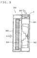
Fig. 3 is a sectional view showing an outline of the structure of the air purifier,
incorporating an ion generating device, of a second embodiment of the invention.
Fig. 4 is a sectional view showing an outline of the structure of the air conditioner,
incorporating an ion generating device, of a third embodiment of the invention.
Fig. 5 is a sectional view showing an outline of the structure of the ion generating
device 101 of a fourth embodiment of the invention.
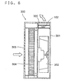
Fig. 6 is a sectional view showing an outline of the structure of the air purifier,
incorporating an ion generating device, of a fifth embodiment of the invention.
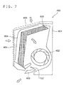
Fig. 7 is a sectional view showing an outline of the structure of the air conditioner,
incorporating an ion generating device, of a sixth embodiment of the invention.
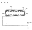
Fig. 8 is a diagram showing an outline of the structure of the ion generating device of
a seventh embodiment of the invention.
Fig. 9 is a sectional view of the ion generating electrode member used in the ion
generating device.
Fig. 10 is a perspective view illustrating an example of how the wire-mesh outer
electrode is formed so as to be put in intimate contact with the outer surface of the glass tube
of the ion generating electrode member.
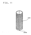
Fig. 11 is a perspective view illustrating another example of how the outer electrode is
formed.
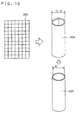
Fig. 12 is a perspective view illustrating an example of how the wire-mesh inner
electrode is formed so as to be put in intimate contact with the inner surface of the glass tube
of the ion generating electrode member.
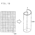
Fig. 13 is a perspective view illustrating another example of how the inner electrode is
formed.
Fig. 14 is a plan view illustrating a displacement between the inner and outer
electrodes that are arranged so as to face each other with the glass tube disposed in between in
the ion generating electrode member.
Fig. 15 is a graph showing the concentrations of negative and positive ions, as
measured at a measurement point located 10 cm away from the side surface of the glass tube
when an alternating-current voltage of 1.3 to 1.8 kV rms having a frequency of 22 kHz was
applied to the inner electrode, with the outer electrode kept at the ground potential, in the ion
generating device.
Fig. 16 is a graph showing the relationship between the concentrations of negative and
positive ions, as measured at a measurement point located 10 cm away from the side surface
of the glass tube, and the survival rate of colon bacilli after one hour when the ion generating
device was installed in a test space 2.0 m long, 2.5 m wide, and 2.7 m high, then colon bacilli
that had been cultured on a culture medium beforehand were sprayed in the test space so that
their concentration was about 500 to 1,500 germs/cc, then the ion generating device was put
into operation, and then the blowing fan was started so that the air inside the test space was
agitated.
Fig. 17 is a graph showing the variation with time of the survival rate of colon bacilli
at different ion concentrations.
Fig. 18A is a graph showing the relationship between the concentration of negative
ions generated and the distance from the side surface of the glass tube when an alternating-current
voltage of 1.1 kV or 1.4 kV having a frequency of 15 kHz was applied to the inner
electrode, with the outer electrode 205 kept at the ground potential, in the ion generating
device, in which the glass tube was a cylindrical tube of Pyrex glass having an internal
diameter of 10 mm, 1.0 mm thick, and 100 mm long, the inner electrode was a wire mesh, 80
mm long and having 60 meshes/inch, produced by plain-weaving wire of stainless steel 304,
0.15 mm across, and the outer electrode was a wire mesh, 80 mm long and having 30
meshes/inch, produced by plain-weaving wire of stainless steel 304, 0.22 across.
Fig. 18B is a graph showing the relationship between the concentration of positive
ions generated and the distance from the side surface of the glass tube when the ion
generating device was put into operation under the same conditions.
Fig. 19 is a graph showing the relationship between the meshes/inch number of the
inner electrode and the amounts of negative and positive ions and of ozone generated, as
measured at a measurement point located 10 cm away from the side surface of the glass tube
when an alternating-current voltage of about 1.8 kV rms was applied to the ion generating
electrode member in the ion generating device, in which the glass tube had an external
diameter of 20mm, was 63 mm long, and was 1.6 mm thick, the inner electrode was 60 mm
long, and had a varying number of meshes/inch, and the outer electrode was woven from wire
0.4 mm across, was 60 mm long, and had 16 meshes/inch.
Fig. 20 is a graph showing the relationship between the meshes/inch number of the
outer electrode and the amounts of negative and positive ions and of ozone generated, as
measured at a measurement point located 10 cm away from the side surface of the glass tube
when an alternating-current voltage of about 1.8 kV rms was applied to the ion generating
electrode member in the ion generating device, in which the glass tube had an external
diameter of 20mm, was 63 mm long, and was 1.6 mm thick, the inner electrode was woven
from wire 0.18 mm across, was 60 mm long, and had 40 meshes/inch, and the outer electrode
was 60 mm long, and had a varying number of meshes/inch.
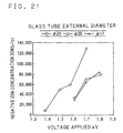
Fig. 21 is a graph showing the relationship between the voltage applied, as expressed
in an rms value, and the concentration of negative ions, as measured at a measurement point
located 10 cm away from the side surface of the glass tube when the inner electrode was
woven from wire 0.18 mm across, was 60 mm long, and had 40 meshes/inch, the outer
electrode was woven from wire 0.4 mm across, was 60 mm long, and had 16 meshes/inch,
and the glass tube was 63 mm long, was 1.2 mm thick, and had a varying external diameter,
specifically 17 mm, 20 mm, or 24 mm in the ion generating device.
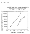
Fig. 22 is a graph showing the relationship between the voltage applied, as expressed
in an rms value, and the concentration of positive ions, as measured at a measurement point
located 10 cm away from the side surface of the glass tube when the ion generating device
was put into operation under the same conditions.
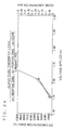
Fig. 23 is a graph showing the relationship between the voltage applied, as expressed
in an rms value, and the concentration of ozone, as measured at a measurement point located
10 cm away from the side surface of the glass tube when the ion generating device was put
into operation under the same conditions.
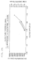
Fig. 24 is a graph showing the relationship between the voltage applied, as expressed
in an rms value, and the concentrations of negative and positive ions and of ozone, as
measured at a measurement point located 10 cm away from the side surface of the glass tube
when the inner electrode was woven from wire 0.18 mm across, was 60 mm long, and had 40
meshes/inch, the outer electrode was woven from wire 0.4 mm across, was 60 mm long, and
had 16 meshes/inch, and the glass tube was 63 mm long, had an external diameter of 20 mm,
and was 1.2 mm thick in the ion generating device.
Fig. 25 is a graph showing the relationship between the voltage applied, as expressed
in an rms value, and the concentrations of negative and positive ions and of ozone, as
measured at a measurement point located 10 cm away from the side surface of the glass tube
when the inner electrode was woven from wire 0.18 mm across, was 60 mm long, and had 40
meshes/inch, the outer electrode was woven from wire 0.4 mm across, was 60 mm long, and
had 16 meshes/inch, and the glass tube was 63 mm long, had an external diameter of 20 mm,
and was 1.6 mm thick in the ion generating device.
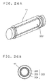
Fig. 26A is a perspective view showing an example of the ion generating electrode
member provided with a catalyst impregnated member impregnated with an ozone
decomposition catalyst.
Fig. 26B is a sectional view of the ion generating electrode member.
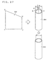
Fig. 27 is a perspective view illustrating an example of how the sheet-form inner
electrode is put in intimate contact with the inner surface of the glass tube in the ion
generating device.
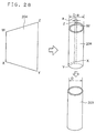
Fig. 28 is a perspective view illustrating another example of how the sheet-form inner
electrode is put in intimate contact with the inner surface of the glass tube in the ion
generating device.
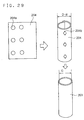
Fig. 29 is a perspective view illustrating another example of how the sheet-form inner
electrode is put in intimate contact with the inner surface of the glass tube in the ion
generating device.
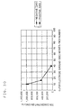
Fig. 30 is a graph showing the amounts of negative and positive ions generated, as
measured at a measurement point located 10 cm away from the side surface of the glass tube
when an alternating-current voltage of about 1.8 kV rms was applied to the ion generating
electrode member of the ion generating device, in which the glass tube had an external
diameter of 20 mm, was 63 mm long, and was 1.6 mm thick, the inner electrode, here a sheet
formed into a cylindrical shape, was 45 mm long, and was 0.08 mm thick, and the outer
electrode, here a mesh formed into a cylindrical shape, was 60 mm long, and had a varying
number of meshes/inch.
Fig. 31 is a graph showing the amounts of negative and positive ions generated, as
measured at a measurement point located 10 cm away from the side surface of the glass tube
when an alternating-current voltage of about 1.8 kV rms was applied to the ion generating
electrode member of the ion generating device, in which the glass tube had an external
diameter of 20 mm, was 63 mm long, and was 1.6 mm thick, the inner electrode, here a sheet
formed into a cylindrical shape, was 0.08 mm thick, and had a varying length, and the outer
electrode, here a mesh formed into a cylindrical shape, was woven from wire 0.22 mm across,
was 60 mm long, and had 16 meshes/inch.
Fig. 32 is a graph showing the amounts of negative and positive ions generated, as
measured at a measurement point located 10 cm away from the side surface of the glass tube
when an alternating-current voltage of about 1.8 kV rms was applied to the ion generating
electrode member of the ion generating device, in which the glass tube had an external
diameter of 20 mm, was 63 mm long, and was 1.6 mm thick, the inner electrode, here a sheet
formed into a cylindrical shape, was 0.08 mm thick, and was 50 mm long, and the outer
electrode, here a mesh formed into a cylindrical shape, was woven from wire 0.22 mm across,
had a varying length, and had 16 meshes/inch.
Fig. 33A is a plan view, partially cutaway, of an example of the mesh-form outer
electrode that is fitted around the glass tube of the ion generating electrode member so as to
be kept in intimate contact with the outer surface thereof.
Fig. 33B is a sectional view showing how the outer electrode is fitted around the glass
tube so as to be kept in intimate contact therewith.
Fig. 34A is a plan view, partially cutaway, of another example of the mesh-form outer
electrode that is fitted around the glass tube of the ion generating electrode member so as to
be kept in intimate contact with the outer surface thereof.
Fig. 34B is a sectional view showing how the outer electrode is fitted around the glass
tube so as to be kept in intimate contact therewith.
Fig. 35 is a sectional view showing an example of the ion generating device of an
eighth embodiment of the invention.
Fig. 36 is an exploded perspective view showing an example of the air purifier,
incorporating an ion generating device, of a ninth embodiment of the invention.
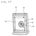
Fig. 37 is a perspective view of the body of the air purifier.
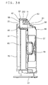
Fig. 38 is a side sectional view of the air purifier.
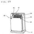
Fig. 39 is a back perspective view of the air purifier.
Fig. 40 is a conceptual diagram illustrating the air flow passage formed inside the air
purifier.
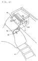
Fig. 41 is an enlarged view of a portion of the bypass passage and the ion generating
electrode member of the air purifier.
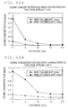
Fig. 42A is a graph showing the relationship between the concentration of the ozone
generated by the ion generating electrode member and the distance from the outlet, as
observed when an alternating-current voltage of 1.1 kV rms was applied to the ion generating
electrode member and the blowing fan was driven in the air purifier.
Fig. 42B is a graph showing the relationship between the concentration of the ozone
generated by the ion generating electrode member and the distance from the outlet, as
observed when an alternating-current voltage of 1.4 kV rms was applied to the ion generating
electrode member and the blowing fan was driven in the air purifier.
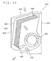
Fig. 43 is a sectional view showing the outline of the structure of the air conditioner,
incorporating an ion generating electrode member, of a tenth embodiment of the invention.
Fig. 44 is a block diagram showing the basic configuration of the controller of the air
conditioner, incorporating an ion generating device, of an eleventh embodiment of the
invention.
Fig. 45 is a block diagram showing the basic configuration of the controller of the air
conditioner, incorporating an ion generating device, of a twelfth embodiment of the invention.
Fig. 46 is a block diagram showing the basic configuration of the controller of the air
conditioner, incorporating an ion generating device, of a thirteenth embodiment of the
invention.
Fig. 47 is an exploded perspective view of the ion generating device unit of a
fourteenth embodiment of the invention.
Fig. 48 is a perspective view of the front member of the ion generating device unit.
Fig. 49A is a sectional view showing how the ion generating electrode member is
fitted in the ion generating device unit.
Fig. 49B is an exposed front view showing how the ion generating electrode member
is fitted.
Fig. 50 is a perspective view of the rear left-hand member of the ion generating device
unit.
Fig. 51 is a perspective view of the rear right-hand member of the ion generating
device unit.
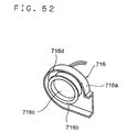
Fig. 52 is a perspective view of the sub blower unit of the ion generating device unit.
Fig. 53 is a front perspective view showing an outline of the structure of the air
conditioner, incorporating an ion generating device unit, of a fifteenth embodiment of the
invention.
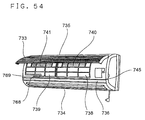
Fig. 54 is a front perspective view of the air conditioner, with its front panel opened.
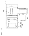
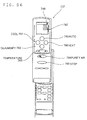
Fig. 55 is an enlarged front view of the display device provided on the body of the air
conditioner.
Fig. 56 is a perspective view of the remote control unit of the air conditioner.
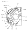
Fig. 57 is a side sectional view of the indoor unit of the air conditioner.
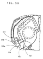
Fig. 58 is a side sectional view of the indoor unit as taken where the ion generating
electrode member is located.
Fig. 59 is a side sectional view of the indoor unit as taken on the left side of where the
ion generating device unit is located.
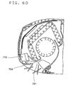
Fig. 60 is a side sectional view of the indoor unit as taken on the right side of where
the ion generating device unit is located.
Fig. 61 is a diagram showing an outline of the overall configuration of the air
conditioner.
Fig. 62 is a perspective view of the indoor unit of the air conditioner, incorporating an
ion generating device unit, of a sixteenth embodiment of the invention.
Fig. 63 is a perspective view of the indoor unit, with its front panel opened.
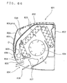
Fig. 64 is an enlarged front view of the liquid crystal display device of the air
conditioner.
Fig. 65 is an enlarged view of the remote control unit of the air conditioner.
Fig. 66 is a side sectional view of the indoor unit of the air conditioner.
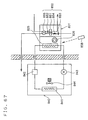
Fig. 67 is a diagram showing an outline of the overall configuration of the air
conditioner.
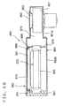
Fig. 68 is a sectional view of the ion generating device unit incorporated in the air
conditioner.
Fig. 69A is a sectional view of the ion generating device unit, with its first outlet
closed and its second outlet opened.
Fig. 69B is a sectional view of the ion generating device unit, with its first outlet
opened and its second outlet closed.
Fig. 70 is a block diagram of the controller of the air conditioner.
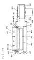
Fig. 71 is a sectional view of another example of the ion generating device unit.
Fig. 72 is a sectional view of yet another example of the ion generating device unit.
Fig. 73 is a perspective view of the indoor unit of an air conditioner provided with a
connector for connection with the ion generating device unit, with its front panel opened.
Fig. 74 is a diagram showing an outline of the configuration of the ion generating
device of a seventeenth embodiment of the invention.
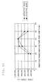
Fig. 75 is a graph showing the variation of ozone concentration observed using the ion
generating device when, in an atmosphere in which the initial concentration of ozone was
0.001 ppm or lower, its power switch was kept in the "on" position for six minutes and then
turned to the "off" position.
Fig. 76 is a side sectional view showing an outline of the structure of the air purifier of
an eighteenth embodiment of the invention.
Fig. 77 is a side sectional view showing an outline of the structure of the air
conditioner of a nineteenth embodiment of the invention.
Fig. 78 is a side sectional view showing an outline of the structure of the air purifier of
a twentieth embodiment of the invention.
Fig. 79 is a graph showing the concentrations of negative and positive ions, as
measured at a measurement point located 20 cm away from the side surface of the glass tube
when an alternating-current voltage of 1.1 to 1.4 kV rms having a frequency of 15 kHz was
applied to the inner electrode, with the outer electrode at the ground potential, in the ion
generating electrode member of the air purifier, in which the glass tube was a cylindrical tube
of Pyrex glass, having an internal diameter of 12 mm, 1.0 mm thick, and 150 mm long, the
inner electrode was a wire mesh, 80 mm long, having 48 meshes/inch, and produced by plain-weaving
wire of stainless steel 304, 0.23 mm across, and the outer electrode was a metal mesh,
80 mm long, having 9 to 100 meshes/inch, and produced by plain-weaving wire of stainless
steel 304, 0.15 to 0.22 mm across.
Fig. 80 is a graph showing the concentration of ozone, as measured at a measurement
point located 20 cm away from the side surface of the glass tube when an alternating-current
voltage was applied to the ion generating electrode member of the air purifier under the same
conditions.
Fig. 81 is a side sectional view showing an outline of the structure of the air
conditioner of a twenty-first embodiment of the invention.
Fig. 82 is a diagram illustrating the structure of the negative and positive ions
generated by the operation of an ion generating device embodying the invention.
Fig. 83 is a diagram illustrating how airborne germs, viruses, odor molecules, and
other foreign particles are decomposed by the action of negative and positive ions.
Best mode for carrying out the invention
Hereinafter, embodiments of the present invention will be described with reference to
the drawings. Fig. 1 is a diagram showing an outline of the structure of the ion generating
device of a first embodiment of the invention. Fig. 2 is a plan view showing the ion
generating electrode member used in this ion generating device 1.
As shown in Fig. 1, the ion generating device 1 of this embodiment is composed of an
ion generating electrode member 2 having a first electrode 4 and a second electrode 5
arranged so as to face each other with a glass plate 3, acting as a dielectric, disposed in
between, and a high alternating-current voltage source 6 connected to the first and second
electrodes 4 and 5 in such a way that the first electrode 4 serves as a voltage application
electrode and the second electrode 5 serves as a grounding electrode.
As shown in Figs. 1 and 2, the ion generating electrode member 2 has the first
electrode 4 kept in intimate contact with one side of the glass plate 3, which is shaped like a
flat plate, and has the second electrode 5 kept in intimate contact with the other side of the
glass plate 3.
In the ion generating electrode member 2 shown in Fig. 2, a glass plate 3 is used as a
dielectric; however, any other insulating material formed into any other shape may be used
instead according to the shape and structure of the apparatus in which the ion generating
device 1 is incorporated.
As the glass plate 3, for example, a flat plate made of Pyrex glass is used. As the
first and second electrodes 4 and 5, for example, wire meshes produced by plain-weaving
wire of stainless steel 316 or 304 are used.
For enhanced ion generation efficiency, the first and second electrodes 4 and 5 are
kept in intimate contact with the glass plate 3. The first and second electrodes 4 and 5 can
easily be put into intimate contact with the glass plate 3 by bonding, by press-fitting with
pieces of wire wound around, by screen printing, or by any other known process.
Now, how the ion generating device 1 structured as described above operates will be
described in terms of practical examples. It is to be understood, however, that the ion
generating device 1 of this embodiment is not limited to any of the examples specifically
described below, but may be implemented with modifications made in operating conditions
and other factors as required.
Example 1
As the glass plate 3, a flat plate of Pyrex glass, 55 mm × 55 mm and 1.0 mm thick,
was used. As the first and second electrodes 4 and 5, wire meshes, each 33 mm × 33 mm
and having 48 meshes/inch, produced by plain-weaving wire of stainless steel 304, 0.23 mm
across, were used. It is to be noted that "meshes/inch" used here as a unit describing how
fine the meshes of a mesh are denotes the number of holes (meshes) found along a length of
one inch; that is, the greater the meshes/inch number of a mesh, the finer its meshes.
By activating the high alternating-current voltage source 6, an alternating-current
voltage of 3.0 kV rms having a frequency of 20 kHz was applied to the first electrode 4, with
the second electrode 5 at the ground potential. Then, using an airborne ion counter, model
83-1001B manufactured by Dan Kagaku Co., Ltd., Japan, the concentrations of negative and
positive ions with mobility of 1cm2 /V· sec or higher were measured at a measurement point
located 10 cm away from the side of the glass plate 3 on which the first electrode 4 is
arranged. The measurement showed the presence of about 60,000 to 70,000 ions/cc of
negative and positive ions. The concentration of ozone was 0.01 to 0.06 ppm.
In this way, by operating the ion generating device 1 with a comparatively low
alternating-current voltage of 3.0 kV rms applied, it is possible to generate a sufficient amount
of negative and positive ions in the air.
Example 2
As the glass plate 3, a flat plate of Pyrex glass, 55 mm × 55 mm and 0.23 mm thick,
was used. As the first and second electrodes 4 and 5, wire meshes, each 33 mm × 33 mm
and having 48 meshes/inch, produced by plain-weaving wire of stainless steel 304, 0.23 mm
across, were used.
By activating the high alternating-current voltage source 6, an alternating-current
voltage of 1.5 kV rms having a frequency of 30 kHz was applied to the second electrode 5,
with the first electrode 4 at the ground potential. Then, using an airborne ion counter, model
83-1001B manufactured by Dan Kagaku Co., Ltd., Japan, the concentrations of negative and
positive ions with mobility of 1cm2 /V· sec or higher were measured at a measurement point
located 10 cm away from the side of the glass plate 3 on which the first electrode 4 is
arranged. The measurement showed that the concentration of negative ions was 14,998
ions/cc, and that the concentration of positive ions was 19,686 ions/cc. The concentration of
ozone was 0.05 ppm.
In this way, by operating the ion generating device 1 with a comparatively low
alternating-current voltage of 1.5 kV rms applied, it is possible to generate a sufficient amount
of negative and positive ions in the air. Moreover, the frequency of the voltage applied is 30
kHz, i.e. beyond the range of human hearing, and therefore the ion generating device 1
operates quietly, with no noise produced by the electric discharge that takes place between the
first and second electrodes 4 and 5.
Next, a second embodiment of the invention will be described with reference to the
drawings. Fig. 3 is a sectional view showing an outline of the structure of the air purifier
300, incorporating an ion generating device 1, of a second embodiment of the invention.
In a rear portion inside the body 301 of the air purifier 300, a blowing fan 302 is
provided. In the front face of the body 301, an air inlet 303 is formed that consists of a
number of holes or slits. On the downstream side of the inlet 303, various filters 304 for
dust removal and deodorization are provided. In the top face of the body 301, an air outlet
305 is formed that consists of a number of holes or slits. In this way, an air flow passage
that leads from the inlet 303 to the filters 304 and then to the outlet 305 is formed inside the
body 301.
Moreover, the ion generating device 1 (see Fig. 1) of the first embodiment described
earlier is arranged with its ion generating electrode member 2 placed in the air flow passage,
in the vicinity of the outlet 305. Here, the high alternating-current voltage source 6 (see Fig.
1) may be provided separately from a power source for driving the blowing fan 302, or may
be shared for this purpose also. In the latter case, a controller (not shown) is additionally
provided so that the driving of the blowing fan 302 and the operation of the ion generating
device 1 can be controlled independently. This permits the ion generating device 1 to be
turned on and off as required while the air purifier 300 is operating, and thus enhances the
usability of the air purifier 300.
When this air purifier 300, structured as described above, starts operating, the blowing
fan 302 starts rotating. As a result, the air sucked through the inlet 303 into the air flow
passage is passed through the filters 304, which remove dust and odors from the air, and is
then blown out through the outlet 305. Meanwhile, if the ion generating device 1 is kept on,
the negative and positive ions generated in the space around the ion generating electrode
member 2 are blown out together with the clean air. In this way, it is possible to kill
airborne germs by the action of negative and positive ions.
Now, how airborne germs are killed and removed by the action of negative and
positive ions will be described briefly. As the ion generating device 1 operates, plasma
discharge occurs between the first and second electrodes 4 and 5 that are arranged so as to
face each other with the glass plate 3 disposed in between. This plasma discharge ionizes
the molecules of water vapor contained in the air into negative and positive ions.
Here, as shown in Fig. 82, as the positive ions, hydrated hydrogen ions H+(H2O) m are
generated, and, as the negative ions, hydrated oxygen ions O2 -(H2O) n are generated. Here, m
and n represent natural numbers.
When these ions attach to the surface of airborne germs, they immediately produce
radical hydroxyl (OH·) as an active species, which robs the germ cells of hydrogen and
thereby kills them. This chemical reaction is an oxidation reaction, and the radial hydroxyl
(OH·) achieves not only sterilization but also deodorization by oxidizing various airborne
molecules that produce odors.
Now, how efficiently the air purifier 300 of this embodiment kills airborne germs will
be described in terms of a practical example. It is to be understood, however, that the air
purifier 300 of this embodiment is not limited to the example specifically described below,
but may be implemented with modifications made in operating conditions and other factors as
required.
Example 3
The air purifier 300 incorporating the ion generating device 1 used in Example 1
described earlier was installed in a test space 2.0 m long, 2.5 m wide, and 2.7 m high. Then,
common bacteria and fungi that had been cultured on a culture medium beforehand were
sprayed in the test space. Simultaneously, the ion generating device 1 was put into operation
under the same conditions as in Example 1 described earlier, and the blowing fan 302 was
started, so that the air purifier 300 started operating.
Then, at predetermined time intervals, using an air sampler, model RCS manufactured
by Biotest AG, Germany, the air inside the test space was extracted at a rate of 40L/min and
sampled for four minutes to measure the number of germs contained in the air. The results
are shown in Table 1.
In three hours after the air purifier 300 started operating, of the common bacteria and
fungi that had originally been present in the test space, 72% and 75%, respectively, were
removed. This proves that the air purifier 300 of this embodiment, incorporating the ion
generating device 1, is capable of satisfactorily killing most airborne germs by the action of
the negative and positive ions that it blows out.
Next, a third embodiment of the invention will be described with reference to the
drawings. Fig. 4 is a sectional view showing an outline of the structure of the air conditioner
400, incorporating an ion generating device 1, of a third embodiment of the invention.
In a rear portion inside the body 401 of the air conditioner 400, a blowing fan 402 is
provided. In the front and top faces of the body 401, an air inlet 403 is formed that consists
of a number of holes or slits. On the downstream side of the inlet 403, various filters 404 for
dust removal and deodorization are provided. On the downstream side of the filters 404, a
heat exchanger 406 is provided. Below the inlet 403 of the body 401, an air outlet 405 is
formed that is provided with a louver for adjusting the direction of the air blown out. In this
way, an air flow passage leading from the inlet 403 to the filters 404, then to the heat
exchanger 406, and then to the outlet 405 is formed inside the body 401.
Moreover, the ion generating device 1 (see Fig. 1) of the first embodiment described
earlier is arranged with its ion generating electrode member 2 placed in the air flow passage,
in the vicinity of the outlet 405. Here, the high alternating-current voltage source 6 (see Fig.
1) may be provided separately from a power source for driving the blowing fan 402, or may
be shared for this purpose also. In the latter case, a controller (not shown) is additionally
provided so that the driving of the blowing fan 402 and of a compressor (not shown) and the
operation of the ion generating device 1 can be controlled independently. This permits the
ion generating device 1 to be turned on and off as required while the air conditioner 400 is
operating, and thus enhances the usability of the air conditioner 400.
When this air conditioner 400, structured as described above, starts operating, the
blowing fan 402 starts rotating. As a result, the air sucked through the inlet 403 into the air
flow passage is passed through the filters 404, which remove dust and odors from the air, is
then passed through the heat exchanger 406, which exchanges heat between the air and a
cooling medium, and is then blown out through the outlet 405. Meanwhile, if the ion
generating device 1 is kept on, the negative and positive ions generated in the space around
the ion generating electrode member 2 are blown out together with the clean air. In this way,
it is possible to kill airborne germs by the action of negative and positive ions.
Now, how efficiently the air conditioner 400 of this embodiment kills airborne germs
will be described in terms of a practical example. It is to be understood, however, that the
air conditioner 400 of this embodiment is not limited to the example specifically described
below, but may be implemented with modifications made in operating conditions and other
factors as required.
Example 4
The air conditioner 400 incorporating the ion generating device 1 used in Example 1
described earlier was installed in a test space 2.0 m long, 2.5 m wide, and 2.7 m high. Then,
common bacteria and fungi that had been cultured on a culture medium beforehand were
sprayed in the test space. Simultaneously, the ion generating device 1 was put into operation
under the same conditions as in Example 1 described earlier, and the blowing fan 402 was
started, so that the air conditioner 400 started operating.
Then, at predetermined time intervals, using an air sampler, model RCS manufactured
by Biotest AG, Germany, the air inside the test space was extracted at a rate of 40L/min and
sampled for four minutes to measure the number of germs contained in the air. The results
are shown in Table 2.
In three hours after the air conditioner 400 started operating, of the common bacteria
and fungi that had originally been present in the test space, 75% and 78%, respectively, were
removed. This proves that the air conditioner 400 of this embodiment, incorporating the ion
generating device 1, is capable of satisfactorily killing most airborne germs by the action of
the negative and positive ions that it blows out.
Next, a fourth embodiment of the invention will be described with reference to the
drawings. Fig. 5 is a sectional view showing an outline of the structure of the ion generating
device 101 of a fourth embodiment of the invention.
As shown in Fig. 5, the ion generating device 101 of this embodiment is composed of
an ion generating electrode member 102 having a first electrode 104 and a second electrode
105 arranged so as to face each other, and a high alternating-current voltage source 106
connected to the first and second electrodes 104 and 105 in such a way that the first electrode
104 serves as a voltage application electrode and the second electrode 105 serves as a
grounding electrode.
As shown in Fig. 5, the ion generating electrode member 102 has the first electrode
104 embedded in a flat-plate-shaped glass plate 103, which acts as a dielectric, and has the
second electrode 105 kept in intimate contact with one side of the glass plate 103.
In the ion generating electrode member 102 shown in Fig. 5, a glass plate 103 is used
as a dielectric; however, any other insulating material formed into any other shape may be
used instead according to the shape and structure of the apparatus in which the ion generating
device 101 is incorporated.
As the glass plate 103, for example, a flat plate made of Pyrex glass is used. As the
first and second electrodes 104 and 105, for example, wire meshes produced by plain-weaving
wire of stainless steel 316 or 304 are used.
The first electrode 104 can be embedded in the glass plate 103 by a known process.
For example, this can easily be achieved by dipping and positioning the first electrode 104 in
molten glass poured into a casting mold for molding the glass into a flat plate of
predetermined size, and then cooling and thereby solidifying the glass.
For enhanced ion generation efficiency, the second electrode 105 is kept in intimate
contact with the glass plate 103. The second electrode 105 can easily be put into intimate
contact with the glass plate 103 by bonding, by press-fitting with pieces of wire wound
around, by screen printing, or by any other known process.
Now, how the ion generating device 101 structured as described above operates will
be described in terms of a practical example. It is to be understood, however, that the ion
generating device 101 of this embodiment is not limited to the example specifically described
below, but may be implemented with modifications made in operating conditions and other
factors as required.
Example 5
As the glass plate 103, a flat plate of Pyrex glass, 35 mm × 35 mm and 3.0 mm thick,
was used. As the first and second electrodes 104 and 105, wire meshes, each 33 mm x 33
mm and having 48 meshes/inch, produced by plain-weaving wire of stainless steel 304, 0.23
mm across, were used. Between the first and second electrodes 104 and 105 arranged so as
to face each other, a gap (indicated by "d" in Fig. 5) of 1.0 mm was secured.
By activating the high alternating-current voltage source 106, an alternating-current
voltage of 3.0 kV rms having a frequency of 20 kHz was applied to the first electrode 104,
with the second electrode 105 at the ground potential. Then, using an airborne ion counter,
model 83-1001B manufactured by Dan Kagaku Co., Ltd., Japan, the concentrations of
negative and positive ions with mobility of 1cm2 /V· sec or higher were measured at a
measurement point located 10 cm away from the side of the glass plate 103 on which the first
electrode 104 is arranged. The measurement showed the presence of about 50,000 ions/cc of
negative and positive ions. The concentration of ozone was 0.05 ppm.
In this way, by operating the ion generating device 101 with a comparatively low
alternating-current voltage of 3.0 kV rms applied, it is possible to generate a sufficient amount
of negative and positive ions in the air. In the ion generating device 101 of this embodiment,
the first electrode 104 is embedded in the glass plate 103, that is, the first electrode 104 is not
exposed to the air. This prevents dust and other foreign particles from settling on and
thereby contaminating the first electrode 104, and thus greatly saves trouble related to
maintenance such as cleaning.
Next, a fifth embodiment of the invention will be described with reference to the
drawings. Fig. 6 is a sectional view showing an outline of the structure of the air purifier
300, incorporating an ion generating device 101, of a fifth embodiment of the invention.
In a rear portion inside the body 301 of the air purifier 300, a blowing fan 302 is
provided. In the front face of the body 301, an air inlet 303 is formed that consists of a
number of holes or slits. On the downstream side of the inlet 303, various filters 304 for
dust removal and deodorization are provided. In the top face of the body 301, an air outlet
305 is formed that consists of a number of holes or slits. In this way, an air flow passage
that leads from the inlet 303 to the filters 304 and then to the outlet 305 is formed inside the
body 301.
Moreover, the ion generating device 101 (see Fig. 5) of the fourth embodiment
described earlier is arranged with its ion generating electrode member 102 placed in the air
flow passage, in the vicinity of the outlet 305. Here, the high alternating-current voltage
source 106 (see Fig. 5) may be provided separately from a power source for driving the
blowing fan 302, or may be shared for this purpose also. In the latter case, a controller (not
shown) is additionally provided so that the driving of the blowing fan 302 and the operation
of the ion generating device 101 can be controlled independently. This permits the ion
generating device 101 to be turned on and off as required while the air purifier 300 is
operating, and thus enhances the usability of the air purifier 300.
When this air purifier 300, structured as described above, starts operating, the blowing
fan 302 starts rotating. As a result, the air sucked through the inlet 303 into the air flow
passage is passed through the filters 304, which remove dust and odors from the air, and is
then blown out through the outlet 305. Meanwhile, if the ion generating device 101 is kept
on, the negative and positive ions generated in the space around the ion generating electrode
member 102 are blown out together with the clean air. In this way, it is possible to kill
airborne germs by the action of negative and positive ions.
Now, how efficiently the air purifier 300 of this embodiment kills airborne germs will
be described in terms of a practical example. It is to be understood, however, that the air
purifier 300 of this embodiment is not limited to the example specifically described below,
but may be implemented with modifications made in operating conditions and other factors as
required.
Example 6
The air purifier 300 incorporating the ion generating device 101 used in Example 5
described earlier was installed in a test space 2.0 m long, 2.5 m wide, and 2.7 m high. Then,
common bacteria and fungi that had been cultured on a culture medium beforehand were
sprayed in the test space. Simultaneously, the ion generating device 101 was put into
operation under the same conditions as in Example 5 described earlier, and the blowing fan
302 was started, so that the air purifier 300 started operating.
Then, at predetermined time intervals, using an air sampler, model RCS manufactured
by Biotest AG, Germany, the air inside the test space was extracted at a rate of 40L/min and
sampled for four minutes to measure the number of germs contained in the air. The results
are shown in Table 3.
In three hours after the air purifier 300 started operating, of the common bacteria and
fungi that had originally been present in the test space, 71% and 76%, respectively, were
removed. This proves that the air purifier 300 of this embodiment, incorporating the ion
generating device 101, is capable of satisfactorily killing most airborne germs by the action of
the negative and positive ions that it blows out.
Next, a sixth embodiment of the invention will be described with reference to the
drawings. Fig. 7 is a sectional view showing an outline of the structure of the air conditioner
400, incorporating an ion generating device 101, of a sixth embodiment of the invention.
In a rear portion inside the body 401 of the air conditioner 400, a blowing fan 402 is
provided. In the front and top faces of the body 401, an air inlet 403 is formed that consists
of a number of holes or slits. On the downstream side of the inlet 403, various filters 404 for
dust removal and deodorization are provided. On the downstream side of the filters 404, a
heat exchanger 406 is provided. Below the inlet 403 of the body 401, an air outlet 405 is
formed that is provided with a louver for adjusting the direction of the air blown out. In this
way, an air flow passage leading from the inlet 403 to the filters 404, then to the heat
exchanger 406, and then to the outlet 405 is formed inside the body 401.
Moreover, the ion generating device 101 (see Fig. 5) of the fourth embodiment
described earlier is arranged with its ion generating electrode member 102 placed in the air
flow passage, in the vicinity of the outlet 405. Here, the high alternating-current voltage
source 106 (see Fig. 5) may be provided separately from a power source for driving the
blowing fan 402, or may be shared for this purpose also. In the latter case, a controller (not
shown) is additionally provided so that the driving of the blowing fan 402 and of a
compressor (not shown) and the operation of the ion generating device 101 can be controlled
independently. This permits the ion generating device 101 to be turned on and off as
required while the air conditioner 400 is operating, and thus enhances the usability of the air
conditioner 400.
When this air conditioner 400, structured as described above, starts operating, the
blowing fan 402 starts rotating. As a result, the air sucked through the inlet 403 into the air
flow passage is passed through the filters 404, which remove dust and odors from the air, is
then passed through the heat exchanger 406, which exchanges heat between the air and a
cooling medium, and is then blown out through the outlet 405. Meanwhile, if the ion
generating device 101 is kept on, the negative and positive ions generated in the space around
the ion generating electrode member 102 are blown out together with the clean air. In this
way, it is possible to kill airborne germs by the action of negative and positive ions.
Now, how efficiently the air conditioner 400 of this embodiment kills airborne germs
will be described in terms of a practical example. It is to be understood, however, that the
air conditioner 400 of this embodiment is not limited to the example specifically described
below, but may be implemented with modifications made in operating conditions and other
factors as required.
Example 7
The air conditioner 400 incorporating the ion generating device 101 used in Example 5
described earlier was installed in a test space 2.0 m long, 2.5 m wide, and 2.7 m high. Then,
common bacteria and fungi that had been cultured on a culture medium beforehand were
sprayed in the test space. Simultaneously, the ion generating device 101 was put into
operation under the same conditions as in Example 5 described earlier, and the blowing fan
402 was started, so that the air conditioner 400 started operating.
Then, at predetermined time intervals, using an air sampler, model RCS manufactured
by Biotest AG, Germany, the air inside the test space was extracted at a rate of 40L/min and
sampled for four minutes to measure the number of germs contained in the air. The results
are shown in Table 4.
In three hours after the air conditioner 400 started operating, of the common bacteria
and fungi that had originally been present in the test space, 74% and 78%, respectively, were
removed. This proves that the air conditioner 400 of this embodiment, incorporating the ion
generating device 101, is capable of satisfactorily killing most airborne germs by the action of
the negative and positive ions that it blows out.
In all the embodiments described thus far, the dielectric used in the ion generating
electrode member of the ion generating device is shaped like a flat plate. However, when
the ion generating device is mounted in an air conditioning apparatus, as is usually the case, it
is essential that the dialectic have a sufficient surface area and simultaneously that the ion
generating electrode member occupy as less space as possible. In the process of finding a
way to achieve an optimum balance between these conflicting requirements, the inventors of
the present invention conceived the idea of making the dielectric cylindrical, which is
reflected in the following embodiments.
Now, a seventh embodiment of the invention will be described with reference to the
drawings. Fig. 8 is a diagram showing an outline of the structure of the ion generating
device 201 of a seventh embodiment of the invention. Fig. 9 is a sectional view of the ion
generating electrode member 202 used in this ion generating device 201.
As shown in Fig. 8, the ion generating device 201 of this embodiment is composed of
an ion generating electrode member 202 having an inner electrode 204 and an outer electrode
205 arranged so as to face each other with a cylindrical glass tube 203, acting as a dielectric,
disposed in between, and a high alternating-current voltage source 206 connected to the inner
and outer electrodes 204 and 205 in such a way that the inner electrode 204 serves as a
voltage application electrode and the outer electrode 205 serves as a grounding electrode.
Here, the outer electrode 205 is used as a grounding electrode to prevent the user from
receiving an electric shock when he or she accidentally touches the ion generating electrode
member 202.
As shown in Fig. 9, the ion generating electrode member 202 has the inner electrode
204 kept in intimate contact with the inner surface of the cylindrical glass tube 203, has the
outer electrode 205 kept in intimate contact with the outer surface of the glass tube 203, and
has a pair of stopping members 7 and 8 fitted at both ends of the glass tube 203.
In the ion generating electrode member 202 shown in Fig. 9, a glass plate 203 is used
as a dielectric; however, any other insulating material formed into any other shape may be
used instead according to the shape and structure of the apparatus in which the ion generating
device 201 is incorporated.
As the glass tube 203, for example, a cylindrical tube made of Pyrex glass is used.
As the inner and outer electrodes 204 and 205, for example, wire meshes produced by plain-weaving
wire of stainless steel 316 or 304 are used.
For enhanced ion generation efficiency, the inner and outer electrodes 204 and 205 are
kept in intimate contact with the glass tube 203. The inner and outer electrodes 204 and 205
can easily be put into intimate contact with the glass tube 203 by a known process.
The outer electrode 205 is put into intimate contact with the glass tube 203, for
example, in the following manner. As shown in Fig. 10, a plain-woven wire mesh is rolled
into a cylindrical shape in such a way that, when the cylinder is formed, the pieces of wire
forming it form an angle of 45° to the axis of the cylinder. Then, opposite side edges of the
wire mesh are welded together with an overlap. In this way, the outer electrode 205 is
produced. Here, the outer electrode 205 is so formed as to have an internal diameter smaller
than the external diameter of the glass tube 203.
Then, force is applied to both ends of the outer electrode 205 along its axis (i.e., in the
figure, from above and from below) so that it is compressed axially. This causes the outer
electrode 205 to expand radially, and, with the outer electrode 205 in this state, the glass tube
203 is inserted in it. When the force ceases to be applied, the outer electrode 205, tending to
restore its original state, expands axially, and thus contracts radially. As a result, the outer
electrode 205 is put into intimate contact with the glass tube 203.
Another way to put the outer electrode 205 into intimate contact with the glass tube
203 is as follows. As shown in Fig. 11, part of the cylindrical outer electrode 205 is formed
into a rib 205a that has an inverted-V-shaped cross section, extends along the axis of the outer
electrode 205, and protrudes radially outward. Moreover, the outer electrode 205 is so
formed as to have an internal diameter smaller than the external diameter of the glass tube 203.
As the glass tube 203 is press-fitted into this outer electrode 205, the angle formed by the two
faces of the inverted-V-shaped rib 205a becomes greater, and thereby makes the internal
diameter of the outer electrode 205 greater. This permits the glass tube 203 to be inserted in
the outer electrode 205. After the glass tube 203 is inserted in the outer electrode 205, the
inverted-V-shaped rib 205a tends to restore its original state, and thereby puts the outer
electrode 205 into intimate contact with the glass tube 203.
On the other hand, the inner electrode 204 is put into intimate contact with the glass
tube 203, for example, in the following manner. As shown in Fig. 12, a plain-woven wire
mesh is rolled into a cylindrical shape to produce the inner electrode 204. Here, the inner
electrode 204 is so formed as to have an external diameter larger than the internal diameter of
the glass tube 203 and have opposite side edges left free, i.e. unwelded together. Then, force
is applied at one side edge of the inner electrode 204 in an axial direction, as if to roll up the
cylinder further, so that the internal diameter of the inner electrode 204, which is otherwise
greater than the internal diameter (D) of the glass tube 203, becomes temporarily smaller (D - α') than it. With the inner electrode 204 in this state, it is inserted in the glass tube 203.
After insertion, when the force ceases to be applied, the inner electrode 204 tends to restore its
original state, and is thereby put into intimate contact with the inner surface of the glass tube
203.
Another way to put the inner electrode 204 into intimate contact with the glass tube
203 is as follows. As shown in Fig. 13, a plain-woven wire mesh is rolled into a cylindrical
shape to produce the inner electrode 204. Here, the inner electrode 204 is so formed as to
have an external diameter greater than the internal diameter of the glass tube 203 and have
opposite side edges left free, i.e. unwelded together. Then, one side edge of the inner
electrode 204 is pulled along the axis thereof in such a way that the inner electrode 204 is
expanded axially as it is twisted. This makes the external diameter of the inner electrode 204
smaller, and thereby permits it to be inserted in the glass tube 203. After insertion, when the
pulling force ceases to be applied, the inner electrode 204 tends to restore its original state,
and is thereby, with its external diameter increased, put into intimate contact with the glass
tube 203.
In Fig. 9, each of the stopping members 7 and 8 is disk-shaped, and has a peripheral
projection 7b or 8b formed in a peripheral portion of one end surface thereof, with a
peripheral groove 7c or 8c formed along the peripheral projection 7b or 8b, in a middle
portion thereof, so as to permit an end of the glass tube 203 to be fitted into it. Moreover,
each of the stopping members 7 and 8 has a side groove 7d or 8d formed in the side surface
thereof so as to permit the ion generating electrode member 202 as a whole to be held in
position. In the center of the stopping member 7 is formed a hole 7a having a thin film
formed therein. This thin film is so processed as to be easily broken when a lead 9
connected to the inner electrode 204 is laid therethrough.
The preferred depth of the peripheral grooves 7c and 8c formed in the stopping
members 7 and 8 is such that, as long as the ends of the glass tube 203 are kept in contact with
the bottoms of the peripheral grooves 7c and 8c, the inner and outer electrodes 204 and 205
do not move relative to each other. If the inner and outer electrodes 204 and 205 move
relative to each other, there occurs a loss in the capacitance that appears when a voltage is
applied between them. Table 5 shows the relationship, as actually observed, between the
change in the positions of the electrodes relative to each other and the loss in capacitance.
Here, as shown in Fig. 14, only movement, or displacement, of the electrodes relative to each
other along the axis of the glass tube 203 is considered.
As Table 5 shows, as long as the inner and outer electrodes 204 and 205 remained in
position, the capacitance was 38.8 pF; when the electrodes 204 and 205 were displaced 5 mm
relative to each other, the capacitance was 36.2 pF, marking a 6.7 % loss relative to the
capacitance with no displacement. In the ion generating electrode member 202 of this
embodiment, fitting the stopping members 7 and 8 at both ends of the glass tube 203 helps
reduce the maximum displacement between the electrodes 204 and 205 to about 2 mm. This
helps minimize the loss in capacitance.
The preferred width of the peripheral grooves 7c and 8c formed in the stopping
members 7 and 8 is slightly smaller than the thickness of the glass tube 203. This permits
the stopping members 7 and 8 to be fitted tightly to the glass tube 203.
The stopping members 7 and 8 may be made of any material, preferably an elastic
material such as rubber so that the stopping members 7 and 8 can easily be fitted to the ends
of the glass tube 203 and that the glass tube 203 can easily be stopped hermetically.
Particularly preferred example of such an elastic material is ethylene-propylene rubber
(EPDM), because it is resistant to ozone generated by the ion generating electrode member
202.
As the leads 9 and 10 connected to the inner and outer electrodes 204 and 205, leads
of any known type may be used. A preferable example of such leads is stainless steel leads
coated with a polyethylene fluoride resin, because they excel in resistance to ozone.
The ion generating electrode member 202 shown in Fig. 9 is assembled, for example,
in the following manner. First, the inner electrode 204 having the lead 9 welded thereto
beforehand is inserted in the glass tube 203. Then, while the lead 9 is being inserted, from
the free end thereof, in the hole 7a of the stopping member 7, the stopping member 7 is fitted
at one end of the glass tube 203. Next, the outer electrode 205 having the lead 10 welded
thereto beforehand is fitted around the glass tube 203, and then the stopping member 8 is
fitted at the other end of the glass tube 203.
Then, the high alternating-current voltage source 206 is connected by way of the lead
9 to the inner electrode 204, serving as a voltage application electrode, and by way of the lead
10 to the outer electrode 205, serving as a grounding electrode. In this way, the ion
generating device 201 shown in Fig. 8 is assembled. Now, by activating the high
alternating-current voltage source 206, it is possible to apply an alternating-current voltage to
the inner electrode 204, with the outer electrode 205 at the ground potential.
Now, how the ion generating device 201 structured as described above operates will
be described in terms of practical examples. It is to be understood, however, that the ion
generating device 201 of this embodiment is not limited to any of the examples specifically
described below, but may be implemented with modifications made in operating conditions
and other factors as required.
First, to study the relationship between the voltage applied, as expressed in an rms
value, and the amount of ions generated, the following experiment was conducted.
Example 8
As the glass tube 203, a cylindrical tube of Pyrex glass, having an external diameter of
10mm, 1.3 mm thick, and 150 mm long, was used. As the inner electrode 204, a sheet of
stainless steel 304, 0.08 mm thick and 80 mm long, was used, and, as the outer electrode 205,
a wire mesh, 100 mm long and having 16 meshes/inch, produced by plain-weaving wire of
stainless steel 304, 0.23 mm across, was used.
By activating the high alternating-current voltage source 206, an alternating-current
voltage of 1.3 to 1.8 kV rms having a frequency of 22 kHz was applied to the inner electrode
204, with the outer electrode 205 at the ground potential. Then, using an airborne ion
counter, model 83-1001B manufactured by Dan Kagaku Co., Ltd., Japan, the concentrations
of negative and positive ions with mobility of 1cm2 /V· sec or higher were measured at a
measurement point located 10 cm away from the side surface of the glass tube 203. The
results are shown in Fig. 15.
When the ion generating device 201 was kept inactive, i.e. when the voltage applied
was 0 V, the concentrations of the negative and positive ions were both about 300 ions/cc. It
was confirmed that, with a voltage of 1.52 kV or higher applied, the ion generating device 201
generated 10,000 or more ions and that, as the voltage, as expressed in an rms value, became
higher, the ion concentration increased.
Next, to evaluate the survival rate of airborne germs against the concentration of ions,
the following experiment was conducted.
Example 9
The ion generating device 201 of Example 8 described above was installed in a test
space 2.0 m long, 2.5 m wide, and 2.7 m high. The atmosphere inside the test space was
kept at a temperature of 25 °C and at a relative humidity of 42 %. Then, colon bacilli that
had been cultured on a culture medium beforehand were sprayed in the test space so that their
concentration was 500 to 1,500 germs/cc. Simultaneously, the ion generating device 201
was put into operation, and the blowing fan 302 was started so that the air inside the test space
was agitated at an air-flow rate of 4 m3/min.
Then, using an airborne ion counter, model 83-1001B manufactured by Dan Kagaku
Co., Ltd., Japan, the concentrations of negative and positive ions with mobility of 1cm2 /V·
sec or higher were measured at a measurement point located 10 cm away from the side
surface of the glass tube 203. One hour after the ion generating device 201 started operating,
using an air sampler, model RCS manufactured by Biotest AG, Germany, the air inside the
test space was extracted at a rate of 40L/min and sampled for four minutes to measure the
number of colon bacilli contained in the air. The results are shown in Fig. 16.
With no ions generated, the survival rate of colon bacilli was 63.5 % after one hour of
natural decay. This means that, if an error of about 10 % is taken into consideration,
achieving a survival rate of 53.5 % or lower in one hour would be regarded as achieving
significant sterilization. As shown in Fig. 16, satisfactory sterilization was confirmed when
the concentrations of the negative and positive ions were both 10,000 ions/cc or higher.
Fig. 17 is a graph showing the variation with time of the survival rate of colon bacilli
at different ion concentrations. This figure shows that, the higher the ion concentration, the
more effectively airborne germs were killed and that, at an ion concentration of 300,000
ions/cc, most of the colon bacilli inside the test space were killed in one hour.
Next, to study the relationship between the voltage applied, as expressed in an rms
value, its frequency, and the amounts of ions and ozone generated, the following experiment
was conducted.
Example 10
As the glass tube 203, a cylindrical tube of Pyrex glass, having an internal diameter of
10mm, 1.0 mm thick, and 100 mm long, was used. As the inner electrode 204, a wire mesh,
80 mm long and having 60 meshes/inch, produced by plain-weaving wire of stainless steel
304, 0.15 mm across, was used, and, as the outer electrode 205, a wire mesh, 80 mm long and
having 30 meshes/inch, produced by plain-weaving wire of stainless steel 304, 0.22 mm
across, was used.
By activating the high alternating-current voltage source 206, different alternating-current
voltages having different frequencies were applied to the inner electrode 205, with the
outer electrode 204 at the ground potential. Then, using an airborne ion counter, model 83-1001B
manufactured by Dan Kagaku Co., Ltd., Japan, the concentrations of negative and
positive ions with mobility of 1cm2 /V· sec or higher were measured at a measurement point
located 10 cm away from the side surface of the glass tube 203. Moreover, using a UV
absorption type ozone monitor, model EG-2001 manufactured by Ebara Jitsugyo Co., Ltd.,
Japan, the concentration of ozone, which is generated as a byproduct when ions are generated,
was measured as well. The results are shown in Table 6.
As shown in Table 6, when a voltage of 44V rms having a frequency of 25 kHz was
applied, ions were detected only in trace amounts. By contrast, when the voltage was raised
tenfold, i.e. to 440 V rms, the concentrations of negative and positive ions sharply rose to
4,966 ions/cc and 13,910 ions/cc, respectively. When the voltage was raised further to
above 1.1 kV rms, at any frequency in the range from 60 Hz to 30 kHz, the presence of
10,000 ions/cc or more of negative and positive ions was confirmed. In particular, at
frequencies of 20 kHz or higher, almost no annoying noise was heard while the ion generating
device 201 was operating. In addition, the concentration of ozone generated was as low as
below about 0.01 ppm.
This proves that, with the ion generating device 201 of this embodiment, by the
application of a comparatively low alternating-current voltage of 1.1 to 2.0 kV rms having a
frequency of 20 kHz or higher, i.e. beyond the range of human hearing, it is possible to
generate 10,000 ions/cc or more of negative and positive ions, i.e. a sufficient amount of ions
to achieve satisfactory sterilization, with minimum noise and with minimum generation,
below a generally admitted level, of hazardous ozone.
Next, to study the relationship between the concentrations of the negative and positive
ions generated by the ion generating device 201 and the distance from the point at which
those ions are generated, the following experiment was conducted.
Example 11
As the glass tube 203, a cylindrical tube of Pyrex glass, having an internal diameter of
10mm, 1.0 mm thick, and 100 mm long, was used. As the inner electrode 204, a wire mesh,
80 mm long and having 60 meshes/inch, produced by plain-weaving wire of stainless steel
304, 0.15 mm across, was used, and, as the outer electrode 205, a wire mesh, 80 mm long and
having 30 meshes/inch, produced by plain-weaving wire of stainless steel 304, 0.22 mm
across, was used.
By activating the high alternating-current voltage source 206, an alternating-current
voltage of 1.1 kV rms or 1.4 kV rms having a frequency of 15 kHz was applied to the inner
electrode 204, with the outer electrode 205 at the ground potential. Then, using an airborne
ion counter, model 83-1001B manufactured by Dan Kagaku Co., Ltd., Japan, the
concentrations of negative and positive ions with mobility of 1cm2 /V· sec or higher were
measured at four measurement points located 20 cm, 30 cm, 40 cm, and 60 cm away from the
side surface of the glass tube 203. The results in different cases are shown in Figs. 18A and
18B.
As shown in these figures, with either of the alternating-current voltages of 1.1 kV rms
and 1.4 kV rms, the farther from the side surface of the glass tube 203, the lower the
concentration of negative and positive ions tend to become. At 20 cm from the side surface
of the glass tube 203, the concentrations of negative and positive ions were both very high,
specifically about 200,000 to 400,000 ions/cc. Thus, a sufficient amount of ions to kill and
remove airborne germs satisfactorily was obtained. At any of the aforementioned
measurement points, the concentration of ozone was as low as 0.01 to 0.25 ppm.
In this way, the higher the alternating-current voltage, as expressed in an rms value,
that is applied to the ion generating electrode member 202, the larger the amount of negative
and positive ions generated, and simultaneously the larger the amount of ozone generated.
Since ozone is anything but essential to human health, it is necessary to minimize the amount
of ozone generated.
First, the relationship between the meshes/inch number of the inner electrode 204 and
the amounts of ions and of ozone generated was studied.
Example 12
Fig. 19 is a graph showing the relationship between the meshes/inch number of the
inner electrode 204 and the amounts of negative and positive ions and of ozone generated, as
measured at a measurement point located 10 cm away from the side surface of the glass tube
203 when an alternating-current voltage of about 1.8 kV rms was applied to the ion generating
electrode member 202, in which the glass tube 203 had an external diameter of 20mm, was 63
mm long, and was 1.6 mm thick, the inner electrode 204 was 60 mm long, and had a varying
number of meshes/inch, and the outer electrode 205 was woven from wire 0.4 mm across, was
60 mm long, and had 16 meshes/inch. Here, the wire diameter of the inner electrode 204
varied according to its meshes/inch number. The concentrations of ions and ozone were
measured using, respectively, an airborne ion counter, model 83-1001B manufactured by Dan
Kagaku Co., Ltd., Japan, and a UV absorption type ozone monitor, model EG-2001
manufactured by Ebara Jitsugyo Co., Ltd., Japan.
Fig. 19 shows that, the greater the meshes/inch number of the inner electrode 204 (i.e.
the finer its meshes), the larger both the amounts of negative and positive ions and of ozone
generated.
Next, the relationship between the meshes/inch number of the outer electrode 205 and
the amounts of ions and of ozone generated was studied.
Example 13
Fig. 20 is a graph showing the relationship between the meshes/inch number of the
outer electrode 205 and the amounts of negative and positive ions and of ozone generated, as
measured at a measurement point located 10 cm away from the side surface of the glass tube
203 when an alternating-current voltage of about 1.8 kV rms was applied to the ion generating
electrode member 202, in which the glass tube 203 had an external diameter of 20mm, was 63
mm long, and was 1.6 mm thick, the inner electrode 204 was woven from wire 0.18 mm
across, was 60 mm long, and had 40 meshes/inch, and the outer electrode 205 was 60 mm
long, and had a varying number of meshes/inch. Here, the wire diameter of the outer
electrode 205 varied according to its meshes/inch number. The concentrations of ions and
ozone were measured using, respectively, an airborne ion counter, model 83-1001B
manufactured by Dan Kagaku Co., Ltd., Japan, and a UV absorption type ozone monitor,
model EG-2001 manufactured by Ebara Jitsugyo Co., Ltd., Japan.
Fig. 20 shows that, the greater the meshes/inch number of the outer electrode 205, the
larger the amounts of negative ions and of ozone generated, but the smaller the amount of
positive ions.
Accordingly, by making the meshes of the inner electrode 204 finer and making the
meshes of the outer electrode 205 coarser, it is possible to generate negative and positive ions
efficiently while minimizing the generation of ozone.
In arrangements where the glass tube 203 is cylindrical in shape, the greater its
external diameter, and the smaller its thickness, the larger its capacitance. The larger the
capacitance of the glass tube 203, the easier it is to generate ions. Therefore, if only efficient
generation of ions is considered, the glass tube 203 should be made as large in external
diameter and as thin as possible. However, as the glass tube 203 is made larger in external
diameter, not only the amount of ions generated, but also the amount of ozone generated
increases. Thus, next, how to increase the amount of ions while minimizing the amount of
ozone was examined.
Example 14
Figs. 21 to 23 show the relationship between the voltage applied, as expressed in an
rms value, and the concentrations of negative and positive ions and of ozone, as measured at a
measurement point located 10 cm away from the side surface of the glass tube 203 when the
inner electrode 204 was woven from wire 0.18 mm across, was 60 mm long, and had 40
meshes/inch, the outer electrode 205 was woven from wire 0.4 mm across, was 60 mm long,
and had 16 meshes/inch, and the glass tube 203 was 63 mm long, 1.2 mm thick, and had a
varying external diameter, specifically 17 mm, 20 mm, or 24 mm. The concentrations of
ions and ozone were measured using, respectively, an airborne ion counter, model 83-1001B
manufactured by Dan Kagaku Co., Ltd., Japan, and a UV absorption type ozone monitor,
model EG-2001 manufactured by Ebara Jitsugyo Co., Ltd., Japan.
Figs. 21 and 22 show that, the higher the voltage applied, the higher the concentrations
of negative and positive ions and that, with the same voltage applied, the concentrations are
higher when the glass tube 203 has an external diameter of 24 mm than when it has an
external diameter of 17 mm or 20 mm.
On the other hand, Fig. 23 shows that the concentration of ozone is far higher when
the glass tube 203 has an external diameter of 24 mm than when it has an external diameter of
17 mm or 20 mm. Comparing how the ion concentrations and the ozone concentration
increase when the external diameter of the glass tube 203 is increased from 20 mm to 24 mm
will make it clear that the increase in the amount of ozone is far larger than the increase in the
amount of ions.
Accordingly, to increase the amount of ions while minimizing the amount of ozone, it
is recommended, at least in the case under discussion, that the cylindrical dielectric be given
an external diameter of 20 mm or less.
Example 15
Figs. 24 and 25 show the relationship between the voltage applied, as expressed in an
rms value, and the concentrations of negative and positive ions and of ozone, as measured at a
measurement point located 10 cm away from the side surface of the glass tube 203 when the
inner electrode 204 was woven from wire 0.18 mm across, was 60 mm long, and had 40
meshes/inch, the outer electrode 205 was woven from wire 0.4 mm across, was 60 mm long,
and had 16 meshes/inch, and the glass tube 203 was 63 mm long, had an external diameter of
20 mm, and was either 1.2 mm or 1.6 mm thick. The concentrations of ions and ozone were
measured using, respectively, an airborne ion counter, model 83-1001B manufactured by Dan
Kagaku Co., Ltd., Japan, and a UV absorption type ozone monitor, model EG-2001
manufactured by Ebara Jitsugyo Co., Ltd., Japan.
Comparing these figures will make it clear that, as the glass tube 203 is made thinner,
the ion concentrations become far higher, and they also come to exhibit greater variations
according to the voltage applied. Thus, it is recommended, at least in the case under
discussion, that the glass tube 203 be made 1.6 mm thick or thinner.
Table 7 shows the results of an experiment conducted to study the relationship
between the external diameter of the glass tube 203, the thickness thereof, and the capacitance
obtained. As described earlier, to increase the amount of ions while minimizing the amount
of ozone, the glass tube 203 is preferably given an external diameter of 20 mm or less and a
thickness of 1.6 mm or less. Accordingly, the preferred capacitance of the glass tube 203 is
40 pF or lower, if variations inevitable in its measurement are taken into consideration.
In addition to minimizing the generation of ozone in this way, impregnating at least
one of the glass tube 203, the inner electrode 204, and the outer electrode 205 with an ozone
decomposition catalyst helps efficiently remove the ozone that is inevitably generated in the
ion generating electrode member. The generated ozone gradually decomposes into oxygen
naturally, and the presence of an ozone decomposition catalyst promotes this decomposition
of ozone into oxygen. As the ozone decomposition catalyst, any known substance can be
used, for example, manganese dioxide, platinum powder, lead dioxide, copper(II) oxide,
nickel.
The impregnation of the ozone decomposition catalyst is achieved, for example, by
dispersing the ozone decomposition catalyst in a binder and then applying it to the surface of
the target member by a coating process such as dipping, spinning, or spraying. The ozone
decomposition catalyst may be impregnated in any amount as determined according to the
amount of ozone generated and other factors.
Alternatively, it is also possible to separately provide a catalyst impregnated member
impregnated with an ozone decomposition catalyst outside the outer electrode 205. Figs.
26A and 26B show an example of the ion generating electrode member 202 provided with
such a catalyst impregnated member 11. Here, a catalyst impregnated member 11 is
provided outside the cylindrical outer electrode 205, at a predetermined distance therefrom.
The catalyst impregnated member 11 is formed as a mesh, and its surface is impregnated with
an ozone decomposition catalyst such as manganese dioxide. The catalyst impregnated
member 11 may cover the whole or a part of the outer electrode 205.
In cases where the ion generating electrode member 202 has both the inner and outer
electrodes 204 and 205 formed as a mesh, if the inner and outer electrodes 204 and 205 move
relative to each other axially, the concentrations of positive and negative ions generated vary
in the range from 1,000 to 180,000 ions/cc and in the range from 3,000 to 180,000 ions/cc,
respectively. This is considered to result from the fact that the electric discharge that takes
place between the inner and outer electrodes 204 and 205, which are here regarded as two
aggregates of lines arranged so as to face each other with the glass tube 203 disposed in
between, weakens as the pieces of wire constituting those electrodes are displaced relative to
each other.
To avoid this problem, the ion generating electrode member 202 may be modified so
as to have the inner electrode 204 formed as a sheet and the outer electrode 205 as a mesh.
Here, forming the inner electrode 204 as a sheet makes it easier to put it into intimate contact
with the glass tube 203 so that the distance between the inner and outer electrodes 204 and
205 is kept substantially fixed. Moreover, even if the inner and outer electrodes 204 and 205
move relative to each other, the inner electrode 204 formed as a sheet minimizes the influence
of the displacement, as long as it is not too large. On the other hand, forming the outer
electrode 205 as a mesh helps prompt the concentration of the electric field, and thus makes it
possible to lower the voltage, as expressed in an rms value, applied between the inner and
outer electrodes 204 and 205.
Here, as the glass tube 203, for example, a cylindrical tube of Pyrex glass is used. As
the inner electrode 204, for example, a sheet of stainless steel 304 or 316 is used, and, as the
outer electrode 205, for example, a wire mesh produced by plain-weaving wire of stainless
steel 316 or 304 is used. In this case, except for the process of putting the inner electrode
204 into intimate contact with the glass tube 203, the ion generating electrode member 202
can be produced in the same manner as described earlier.
The inner electrode 204 is put into intimate contact with the glass tube 203, for
example, in the following manner. As shown in Fig. 27, sheet metal is pressed to blank out a
sheet-form electrode having the shape of a quadrilateral STUV. Here, side ST is parallel to
side UV, angle T = angle V = 90°, angle S is an acute angle, and angle V is an obtuse angle.
The inner electrode 204 is produced by rolling this sheet-form electrode into a cylindrical
form in such a way that sides ST and UV are parallel to the axis of the cylinder and that the
inner electrode 204 thus produced has an external diameter larger than the internal diameter of
the glass tube 203. Here, opposite side edges (sides ST and UV) of the inner electrode 204
are left free, i.e. unwelded together. The resulting cylinder is substantially flat at one end
corresponding to side TU, and has the acute-angle corner S protruding from the obtuse-angle
corner V at the other end.
Alternatively, it is also possible to press sheet metal so as to blank out a sheet-form
electrode having a shape composed solely of non-90° angles, i.e. acute or obtuse angles, for
example a trapezoid WXYZ as shown in Fig. 28. The inner electrode 204 is produced by
rolling this sheet-form electrode into a cylindrical form in such a way that its parallel sides
WX and ZY are parallel to the axis of the cylinder and that the inner electrode 204 so
produced has an external diameter larger than the internal diameter of the glass tube 203.
Here, angles W and X are obtuse angles, and angles Y and Z are acute angles. Opposite side
edges (sides WX and ZY) of the inner electrode 204 are left free, i.e. unwelded together.
The resulting cylinder has the two acute-angle corners Y and Z protruding outward.
Shapes composed solely of non-90° angles include a variety of shapes from polygons,
such as triangles, quadrilaterals, pentagons, and hexagons, to shapes that are almost circular
but has one corner, i.e. any shape that can be rolled into a cylindrical shape with at least one
corner protruding outward.
Then, force is applied at one side edge of the inner electrode 204, thus produced by
rolling a sheet-form electrode into a cylindrical shape, in a tangential direction, as if to roll up
the cylinder further, so that the internal diameter of the inner electrode 204, which is
otherwise greater than the internal diameter (D) of the glass tube 203, becomes temporarily
smaller (D - α) than it. With the inner electrode 204 in this state, it is inserted in the glass
tube 203. After insertion, when the tangential force ceases to be applied, the inner electrode
204 tends to restore its original state, and is thereby put into intimate contact with the inner
surface of the glass tube 203.
The ion generating electrode member 202 thus produced was subjected to a test in
which an alternating-current voltage was applied thereto to generate ions. The test showed
that this ion generating electrode member 202 could generate negative and positive ions stably,
both in concentrations of 400,000 to 600,000 ions/cc, even if the inner and outer electrodes
204 and 205 moved relative to each other, as long as the displacement was not too large. For
comparison, forming the inner and outer electrodes 204 and 205 both as a sheet yielded
almost no ions.
In this arrangement, where the inner electrode 204 is formed by rolling a sheet-form
electrode into a cylindrical shape with at least one corner protruding from one end of the
cylinder, making the inner electrode 204 shorter than the outer electrode 205 in the direction
of their length permits the high alternating-current voltage to discharge from around such a
corner of the inner electrode 204 to a wide area on the mesh-form outer electrode 205. This
helps achieve a proper balance between the amounts of negative and positive ions. By
contrast, making the inner electrode 204 longer than the outer electrode 205 in the direction of
their length causes the high alternating-current voltage to discharge from around a corner of
the inner electrode 204 to a localized spot on the mesh-form outer electrode 205. This tips
the balance between the amounts of negative and positive ions in favor of positive ions.
Another way of putting the inner electrode 204 into intimate contact with the glass
tube 203 is as follows. As shown in Fig. 29, a plurality of holes 204a are formed in sheet
metal, then the sheet metal is pressed to form projections 204b around the holes, and then the
inner electrode 204 is produced by rolling this sheet metal into a cylindrical shape in such a
way that the projections 204b around the holes 204a protrude toward the glass tube 2 and that
the inner electrode 204 thus produced has an external diameter larger than the internal
diameter of the glass tube 2. Here, opposite side edges of the inner electrode 204 are left
free, i.e. unwelded together. Moreover, the rolling is performed in such a way that, in the
resulting cylinder, the projections 204b formed around the holes 204a protrude toward the
inner surface of the glass tube 2.
Then, force is applied at one side edge of the inner electrode 204, thus produced by
rolling a sheet-form electrode into a cylindrical shape, as if to roll up the cylinder further so
that the internal diameter of the inner electrode 204, which is otherwise greater than the
internal diameter (D) of the glass tube 203, becomes temporarily smaller (D - α) than it.
With the inner electrode 204 in this state, it is inserted in the glass tube 203. After insertion,
when the force ceases to be applied, the inner electrode 204 tends to restore its original state,
and is thereby put into intimate contact with the inner surface of the glass tube 203.
As a result, between the sheet-form inner electrode 204 and the mesh-form outer
electrode 205 that face each other with the glass tube 203 disposed in between, electric
discharge takes place from a plurality of surfaces to a plurality of points. This ensures strong
electric discharge on the surfaces. Moreover, the projections 204b prompt electric discharge
by limiting the spots at which electric discharge occurs. This ensures stable electric
discharge.
Example 16
Fig. 30 shows the amounts of negative and positive ions generated, as measured at a
measurement point located 10 cm away from the side surface of the glass tube 203 when an
alternating-current voltage of about 1.8 kV rms was applied to the ion generating electrode
member 202, in which the glass tube 203 had an external diameter of 20 mm, was 63 mm
long, and was 1.6 mm thick, the inner electrode 204, here a sheet formed into a cylindrical
shape, was 45 mm long, and was 0.08 mm thick, and the outer electrode 205, here a mesh
formed into a cylindrical shape, was 60 mm long, and had a varying number of meshes/inch.
Here, the wire diameter of the outer electrode 205 varied according to its meshes/inch number.
The concentrations of ions were measured using an airborne ion counter, model 83-1001B
manufactured by Dan Kagaku Co., Ltd., Japan.
As shown in Fig. 30, the meshes/inch number of the outer electrode 205 greatly
influences the amount of ions generated; specifically, the smaller its meshes/inch number, the
larger the amounts of ions generated. Without the holes, the inner electrode 204 produced
smaller amounts of ions.
Example 17
Fig. 31 shows the amounts of negative and positive ions generated, as measured at a
measurement point located 10 cm away from the side surface of the glass tube 203 when an
alternating-current voltage of about 1.8 kV rms was applied to the ion generating electrode
member 202, in which the glass tube 203 had an external diameter of 20 mm, was 63 mm
long, and was 1.6 mm thick, the inner electrode 204, here a sheet formed into a cylindrical
shape, was 0.08 mm thick, and had a varying length, and the outer electrode 205, here a mesh
formed into a cylindrical shape, was woven from wire 0.22 mm across, was 50 mm long, and
had 16 meshes/inch. Here, the wire diameter of the outer electrode 205 varied according to
its meshes/inch number. The concentrations of ions were measured using an airborne ion
counter, model 83-1001B manufactured by Dan Kagaku Co., Ltd., Japan.
As shown in Fig. 31, the amounts of ions generated are low when the sheet-form inner
electrode 204 and the mesh-form outer electrode 205 are made equally long, and the amounts
of ions increase as the inner electrode 204 is made shorter than the outer electrode 205.
However, when the inner electrode 204 is made too short, the amounts of ion start to drop.
Example 18
Fig. 32 shows the amounts of negative and positive ions generated, as measured at a
measurement point located 10 cm away from the side surface of the glass tube 203 when an
alternating-current voltage of about 1.8 kV rms was applied to the ion generating electrode
member 202, in which the glass tube 203 had an external diameter of 20 mm, was 63 mm
long, and was 1.6 mm thick, the inner electrode 204, here a sheet formed into a cylindrical
shape, was 0.08 mm thick, and was 50 mm long, and the outer electrode 205, here a mesh
formed into a cylindrical shape, was woven from wire 0.22 mm across, had a varying length,
and had 16 meshes/inch. The concentrations of ions were measured using an airborne ion
counter, model 83-1001B manufactured by Dan Kagaku Co., Ltd., Japan.
As shown in Fig. 32, as the outer electrode 205 is made shorter than the inner
electrode 204, the amounts of ions generated increase, but positive ions tend to increase at a
far higher rate than negative ions. Therefore, it is advisable that the outer electrode 205 be
made longer than the inner electrode 204.
As shown in Fig. 33A, parts of both ends of the outer electrode 205 may be folded
back and curled to form folded portions 205a so that the outer electrode 205 is double-layered
at both ends. In this case, the outer electrode 205 is so formed as to have an internal
diameter slightly smaller than the external diameter of the glass tube 203.
Then, the outer electrode 205 is press-fitted into position around the glass tube 203.
This puts the folded portions 205a, i.e. the double-layered portions, of the outer electrode 205
into intimate contact with the glass tube 203, leaving, as shown in Fig. 33B, spaces A around
which the folded portions 205a do not make contact with the glass tube 203. Then, the outer
electrode 205 is, in several positions along its axis, tightened from outside with elastic
tightening members so as to be fixed to the glass tube 203. This puts the outer electrode 205
as a whole into intimate contact with the glass tube 203.
Example 19
An alternating-current voltage of 2.1 kV rms was applied to the ion generating
electrode member 202 having folded portions 205a formed at both ends of the outer electrode
205 as shown in Fig. 33B, in which the glass tube 203 had an external diameter of 20 mm,
was 150 mm long, and was 1.2 mm thick, the inner electrode 204 was 95 mm long, and was
0.08 mm thick, and the outer electrode 205 was woven from wire 0.4 mm across, was 98 mm
long, and had 30 meshes/inch.
As a result, at a measurement point located 10 cm away from the side surface of the
glass tube 203, negative and positive ions were obtained in concentrations of 400,000 to
600,000 ions/cc, with reproducibility of 80% for the total number of ion generating electrode
members 202 produced in the same manner. The concentrations of ions were measured
using an airborne ion counter, model 83-1001B manufactured by Dan Kagaku Co., Ltd.,
Japan.
As an alternative to curling both ends of the outer electrode 205, it is also possible, as
shown in Fig. 34A, to form bent portions 205b there by bending the corresponding edges of
the originally rectangular or square mesh material of the outer electrode 205 into an inward
pointing L-shape. These bent portions 205b may be formed at any angle as long as, when
the outer electrode 205 is formed by rolling the mesh material into a cylindrical shape, the tip
portions of the bent portions 205b can be put into intimate contact with the glass tube 203 all
around the periphery thereof as shown in Fig. 34B. The bent portions 205b may have an
arch-shaped section as long as their tip portions make contact with the glass tube 203,
achieving the same purpose. Thereafter, as required, spot welding is applied to four corners
of the mesh material to prevent it from getting loose, and then the mesh material is rolled into
a cylindrical shape.
Here, the outer electrode 205 is so produced as to have an internal diameter slightly
larger than the external diameter of the glass tube 203. Then, the outer electrode 205 is
press-fitted into position around the glass tube 203. This puts the bent portions 205b at both
ends of the outer electrode 205 into intimate contact with the glass tube 203. When fitted
around the glass tube 203, the bent portions 205b leave, as shown in Fig. 34B, slight spaces B
between themselves and the glass tube 203. Then, the outer electrode 205 is, in several
positions along its axis, fixed to the glass tube 203 with locking members, and is thereby
brought into intimate contact with the glass tube 203.
Moreover, the electrodes 204 and 205 are mounted on the glass tube 203 in such a way
that their axially central portions face each other. This makes it possible to arrange the inner
and outer electrodes 204 and 205 in such a way that, when the outer electrode 205 is projected
onto the inner electrode 204, the ends of the inner electrode 204 lie inside the projected view
of the outer electrode 205. Specifically, here, the error in position between an end of the
inner electrode 204 and the corresponding end of the outer electrode 205 falls within a range
of about 0.5 to 1.0 mm.
This arrangement ensures stable electric discharge between a corner at an end of the
sheet-form inner electrode 204 (corners Y and Z in Fig. 20) and the outer electrode 205 that is
kept in intimate contact with the glass tube 203. Here, stable electric discharge is considered
to result from the fact that, whereas the inner electrode 204 to which the voltage is applied has
a pointed end, the outer electrode 205 acts as an aggregate of lines kept in contact with the
glass tube 203, and thus electric discharge occurs, if considered locally, between a point and a
surface
Example 20
An alternating-current voltage of 2.1 kV rms was applied to the ion generating
electrode member 202 having L-shaped bent portions 205b formed at both ends of the outer
electrode 205 with the tip portions of those bent portions 205b kept in contact with the glass
tube 203 as shown in Fig. 34B, in which the glass tube 203 had an external diameter of 20
mm, was 150 mm long, and was 1.2 mm thick, the inner electrode 204 was 95 mm long, and
was 0.08 mm thick, and the outer electrode 205 was woven from wire 0.4 mm across, was 98
mm long, and had 30 meshes /inch.
As a result, at a measurement point located 10 cm away from the side surface of the
glass tube 203, negative and positive ions were obtained in concentrations of 400,000 to
600,000 ions/cc, with reproducibility of 100% for the total number of ion generating electrode
members 202 produced in the same manner. Here, it was confirmed that the electric
discharge occurring between the inner and outer electrodes 204 and 205 was more stable
when, of the bent portions 205b that might be formed at both ends of the outer electrode 205
and kept in contact with the glass tube 203, only one was formed than when none was formed,
and that the electric discharge was still more stable when both of those bent portions 205b
were formed than when only one was formed. The concentrations of ions were measured
using an airborne ion counter, model 83-1001B manufactured by Dan Kagaku Co., Ltd.,
Japan.
As described above, in the ion generating device 201 of this embodiment, the use of a
cylindrical dielectric makes the handling of the ion generating electrode member 202 easy,
helps save space, and stabilizes the performance of the ion generating device 201. This
permits the ion generating device 201 to be advantageously incorporated in various air
conditioning apparatus.
Now, an eighth embodiment of the invention will be described with reference to the
drawings. Fig. 35 is a sectional view showing an example of the ion generating device 500
of an eighth embodiment of the invention. One of the key features of this ion generating
device 500 is that it is provided with the ion generating electrode member 202 of the ion
generating device 201 (see Fig. 8) described above in connection with the seventh
embodiment to generate negative and positive ions and kill and remove airborne germs
therewith.
The ion generating device 500 is provided with an ion generating electrode member
202, a blower 501, a filter (not shown), and a high-voltage power supply circuit 502
composed of a high-voltage transformer 502a and a control circuit board 502b. Air taken in
through an inlet (not shown) passes through the filter, which removes dust from the air, and
then reaches the blower 501, which blows the air to the ion generating electrode member 202.
The ion generating electrode member 202, when fed with a predetermined alternating-current
voltage from the high-voltage power supply circuit 502, generates negative and positive ions
from the air. By the action of these positive and negative ions, airborne germs are removed
from the air. On the other hand, ozone is also generated as a byproduct when the negative
and positive ions are generated. Usually, the amount of ozone generated in the ion
generating electrode member 202 is within a permissible range. However, the amount of
ozone contained in the air blown out of the device may be reduced, as required, by
impregnating the ion generating electrode member 202 with an ozone decomposition catalyst
or separately providing a catalyst impregnated member 11 (see Fig. 26A) in the air flow
passage. The air, having ions generated therein and airborne germs removed therefrom in
this way, is then blown out of the device.
This ion generating device 500 can be made compact, and can thus be installed
anywhere with minimum space; it can even be hung on a wall. Moreover, by building the
ion generating device 500 as a unit, and designing various products to permit the unit to be
optionally attached thereto, it is possible to enhance the usability of those products.
Next, a ninth embodiment of the invention will be described with reference to the
drawings. Fig. 36 is an exploded perspective view showing an example of the air purifier,
incorporating an ion generating device 201, of a ninth embodiment of the invention. The air
purifier is provided with a body 50 fixed on a base 51, a filter 60 housed in a housing 51 (see
Fig. 37) formed in a front portion of the body 50, a front cover 70 for covering the filter 60 so
housed, and a rear cover 80 for covering the back of the body 50.
The filter 60 is composed of, from the front side, a pre-filter 61, a deodorizing filter 62,
and a dust collecting filter 63. The pre-filter 61 collects dust and other foreign particles
contained in the air sucked into the air purifier. A preferred material for the pre-filter 61 is,
for example, polypropylene, which offers high air resistance. The deodorizing filter 62 has a
three-layer structure; specifically, it is produced by stretching a piece of nonwoven fabric of
polyester on a rectangular frame, then evenly dispersing activated charcoal over it, and then
stretching another piece of nonwoven fabric of polyester over it. This structure absorbs and
removes odors, such as acetaldehyde, ammonia, and acetic acid, from the air. The dust
collecting filter 63 is produced by folding up a filtering material consisting of an electret-type
meltblown nonwoven fabric ("Toraymicron" manufactured by Toray Industries Inc., Japan)
and a structural material (a polyester/vinylon-based nonwoven fabric), then
thermocompression-bonding antibacterial sheets over the top and bottom surfaces thereof,
then inserting the thus obtained filtering element into a frame, and then fusion-bonding the
frame to the filtering element. This dust colleting filter 63 collects particularly small dust
and other foreign particles in the air.
The front cover 70 is so curved as to be slightly convex frontward in the center thereof
as seen in a horizontal section, and has an inlet 71, through which indoor air is sucked in,
formed in the center thereof as seen in a front view. The front cover 70 is locked to the body
50 with a predetermine distance secured in between, and the gap between the front cover 70
and the body 50 is used as a side inlet 72 (see Fig. 38), through which indoor air is sucked in.
Fig. 37 shows a perspective view of the body 50. The body 50 has the shape of a
vertically extending rectangular prism, has a housing 51, for housing the filter 60, formed as a
rectangular recess in the front face thereof, and has a vent, consisting of a number of radiating
elongate holes 52, formed in the center of the bottom surface of the housing 51. At the
center of the vent 52 is formed a further recess 53 for housing a motor 56 (see Fig. 38). On
the back side of this recess 53, a fan 57 (see Fig. 38) is fitted on the spindle of the motor 56.
In an upper portion of the front face of the body 50 are formed an operation portion 54,
including various switches and indicators such as a power switch, air quantity/timer/operation
mode setting/selecting switches, and operation status indicator lamps, and a sight window 55
that permits the user to visually check the operation status of the ion generating electrode
member.
Fig. 39 shows a back perspective view of the air purifier. In an inclined surface
formed in an upper portion of the rear cover 80, an outlet 81 consisting of a number of four-column
slit holes is formed, and, in an upper left-hand portion of the inclined surface, an ion
outlet 82 consisting of a number of slit holes is formed. Moreover, in an upper central
portion of the rear cover 80, a grip 84 is formed as a rectangular recess, and, in two corners of
a central, flat portion of the rear cover 80, hanging slots 85 are provided to permit the air
purifier to be hung on a wall.
Fig. 38 shows a side sectional view of the air purifier. When the motor 56 rotates the
fan 57, air is sucked in through the inlet 71 and the side inlet 72 formed in the front cover 70.
The air thus sucked in then passes through the filter 60 and reaches the fan 57, by which the
air is made to flow upward, toward the outlet 81. On the way, a bypass passage 59 is formed
that leads to the ion generating electrode member 202 fitted in an upper portion (in an upper
right-hand portion as seen in a front view) of the body 50, so that part of the air that is about
to be discharged is directed through the bypass passage 59 to the ion generating electrode
member 202 (see Fig. 40). The ion generating electrode member 202 generates negative and
positive ions simultaneously from part of the air directed thereto, and thus air containing those
negative and positive ions is discharged through the ion outlet 82. When the ions are
generated, ozone is also generated. However, this ozone is decomposed into oxygen by the
catalyst impregnated member 11 impregnated with an ozone decomposition catalyst provided
outside the outer electrode 205 (see Fig. 9). This reduces the amount of ozone contained in
the air discharged through the ion outlet 82.
Fig. 41 shows an enlarged view of a portion of the bypass passage 59 and the ion
generating electrode member 202. The bypass passage 59 has a passage inlet 58 that is open
toward the rotation direction of the fan 57, so that part of the air blown by the fan 57 is taken
into the bypass passage 59 through the passage inlet 57. The bypass passage 59 first runs
straight (in the rotation direction of the fan 57), then changes its course toward the front of the
air purifier to run underneath the ion generating electrode member 202, and then charges its
course upward to reach the ion generating electrode member 202.
In Fig. 38, in a portion of the front face of the body that faces the ion generating
electrode member 202, the sight window 55 is provided to permit the user to check the
operation status of the ion generating electrode member 202. On the surface of the sight
window 55, a protection cover 40 is fitted to prevent air from leaking out from inside the air
purifier. Preferably, this protection cover 40 is formed as part of a sheet that protects the
whole front face of the body 50 including the sight window 55 (except for the housing 51) and
that thus has an opening formed in a portion thereof that corresponds to the housing 51. For
example, the sheet is made of a transparent resin material, and has a metallic silver color
applied to or silk-screened on the back surface thereof. This gives the air purifier a massive
look when seen from the front. Making the front cover 70 see-through additionally, in
combination with such coloring of the protection cover 40, gives the air purifier a refreshing,
cleanly look.
Now, an example of how the air purifier operates will be described. When the power
switch on the operation portion 54 is turned to the "on" position, the air purifier starts
operating in an automatic mode. The motor 56 rotates the fan 57, and air is sucked into the
air purifier through the inlet 71 and the side inlet 72 formed in the front cover 70. From the
air, the pre-filter 61 collects relatively large dust and other foreign particles, the deodorizing
filter 62 absorbs and removes odors, and the dust collecting filter 63 collects relatively small
dust and other foreign particles. The air, thus cleared of odors as well as dust and other
foreign particles by the filter 60, is then discharged out of the air purifier by the fan 57.
Meanwhile, part of the air is blown into the bypass passage 59 through the passage inlet 58 so
as to be directed to the ion generating electrode member 202.
An alternating-current voltage of about 1.75 kV starts being applied to the ion
generating electrode member 202 as soon as the air purifier starts operating. Thus, the ion
generating electrode member 202 generates negative and positive ions from the air taken in,
and also generates, as a byproduct, ozone simultaneously. Here, the negative and positive
ions are generated in concentrations of 20,000 ions/cc, and the ozone in a concentration of
0.01 ppm or lower: By the action of the negative and positive ions thus generated
simultaneously by the ion generating electrode member, airborne germs are removed from the
air.
The concentrations of ions generated can be increased by increasing the alternating-current
voltage applied to the ion generating electrode member 202. However, increasing
the alternating-current voltage also increases the amount of ozone generated. To generate
ions efficiently while minimizing the generation of ozone, it is advisable that the alternating-current
voltage applied to the ion generating electrode member be 2.0 kV or lower. With the
alternating-current voltage fulfilling this condition, it is possible to reduce the concentration
of ozone down to 1/10 or lower of the generally admitted maximum level (0.1 ppm). If the
ion generating electrode member 202 is impregnated with an ozone decomposition catalyst, or
a catalyst impregnated member 11 impregnated with an ozone decomposition catalyst is
provided separately, it is possible to raise the upper limit of the applied voltage to 2.5 kV and
thereby generate ions in higher concentrations.
Next, to evaluate the deodorization performance of the air purifier of this embodiment
against odors in the air, the following experiment was conducted.
Example 21
The air purifier described above, incorporating the ion generating device 201 used in
Example 10 described earlier, was installed in a test space 2.0 m long, 2.5 m wide, and 2.7 m
high. After the atmosphere inside the test space was replaced with clean, dry air, five
cigarettes were burned. Simultaneously, an alternating-current voltage of 1.1 kV rms having
a frequency of 25 kHz was applied to the ion generating electrode member 202, and the motor
56 was activated to rotate the fan 57 at an air-flow rate of 4 m3/sec, so that the air purifier
started operating. Then, using a gas detector tube, the concentrations of ammonia, acetic
acid, styrene, and carbon monoxide were measured at the time the air purifier started
operating and 30 minutes thereafter. The experiment showed that 30 minutes' operation of
the air purifier resulted in removal of 35% of the ammonia, 65% of the acetic acid, 58% of the
styrene, and 90% of the carbon monoxide.
In this way, it was confirmed that the air purifier of this embodiment achieved
satisfactory deodorization by quickly decomposing typical odors in households by the action
of negative and positive ions.
Next, the sterilization performance of the air purifier of this embodiment against
airborne germs will be described in terms of practical examples. It is to be understood,
however, that the air purifier of this embodiment is not limited to the examples specifically
described below, but may be implemented with modifications made in operating conditions
and other factors as required.
Example 22
The air purifier described earlier, incorporating the ion generating device 201 used in
Example 8 described earlier, was installed in a test space 2.0 m long, 2.5 m wide, and 2.7 m
high. Then, common bacteria and fungi that had been cultured on a culture medium
beforehand were sprayed in the test space. Simultaneously, the ion generating device 201
was put into operation under the same conditions as in Example 8 described earlier, and the
motor 56 was started to rotate the blowing fan 57, so that the air purifier started operating.
Then, at predetermined time intervals, using an air sampler, model RCS manufactured
by Biotest AG, Germany, the air inside the test space was extracted at a rate of 40L/min and
sampled for four minutes to measure the number of germs contained in the air. The results
are shown in Table 8.
In two hours after the air purifier started operating, of the common bacteria and fungi
that had originally been present in the test space, 77% and 80%, respectively, were removed.
This proves that the air purifier of this embodiment, incorporating the ion generating device
201, is capable of satisfactorily killing most airborne germs by the action of the negative and
positive ions that it blows out.
As described earlier in connection with the second and fifth embodiments, the air
purifier 300 (see Figs. 3 and 6) incorporating the ion generating electrode member 1 having a
flat-plate-shaped glass plate 3 required three hours to kill and remove 70% or more of the
germs inside the test space, as Example 3 (see Table 1) and Example 6 (see Table 3)
exemplify. By contrast, the air purifier of this embodiment, incorporating the ion generating
electrode member 202 having a cylindrical glass tube 203, requires one hour less. This
proves superiority of the cylindrical glass tube 203.
Next, to check how much of the ozone that is generated inevitably together with the
negative and positive ions in the space around the ion generating electrode member 202 is
discharged through the outlet 81 of the air purifier by the blowing fan 57, the following
experiment was conducted.
Example 23
An ozone concentration checker (not shown) was installed at each of five
measurement points located 0 cm, 5 cm, 10 cm, 15 cm, and 20 cm away from the outlet 81 of
the air purifier used in Example 22 described above. Then, an alternating-current voltage of
1.1 kV rms is applied to the ion generating electrode member 202, and the blowing fan 57 was
started at an air-flow rate of 4 m3/min or 0.8 m3/min. In this state, the concentration of
ozone was measured at each of the aforementioned measurement points. For comparison,
with an alternating-current voltage of 1.4 kV rms applied under the same conditions, the
concentration of ozone was measured in the same manner. The results in different cases are
shown in Figs. 42A and 42B. The concentration of ozone was measured using a UV
absorption type ozone monitor, model EG-2001 manufactured by Ebara Jitsugyo Co., Ltd.,
Japan.
As shown in these figures, the higher the voltage applied, as expressed in an rms value,
and the higher the air-flow rate at which the blowing fan 57 is driven, the higher the
concentration of ozone. The concentration of ozone, however, drops quickly with the
increasing distance from the outlet 81. Accordingly, by controlling the voltage applied, as
expressed in an rms value, and the air-flow rate (i.e. the number of revolutions) at which the
blowing fan 57 is driven, it is possible to control the amount of ozone that is generated as a
byproduct by the ion generating electrode member 202.
Thus, an ozone sensor (not shown) may be additionally provided in the vicinity of the
ion generating electrode member 202 to continually monitor the concentration of ozone, and
the air purifier may be so configured that, according to the results of the detection by the
ozone sensor, the high alternating-current voltage, as expressed in an rms value, applied to the
ion generating electrode member 202 is determined in such a way as to keep the concentration
of ozone below a predetermined admitted level.
This makes it possible to realize an air purifier that can kill and remove airborne germs
by the action of negative and positive ions while keeping the concentration of the ozone
generated by the ion generating electrode member 202 below an admitted level. As the
aforementioned admitted level of the concentration of ozone, it is proper to use the level 0.1
ppm stipulated by Japan Society for Occupational Health.
Now, a tenth embodiment of the invention will be described with reference to the
drawings. Fig. 43 is a sectional view showing the outline of the structure of the air
conditioner 400, incorporating an ion generating electrode member 202, of a tenth
embodiment of the invention.
In a rear portion inside the body 401 of the air conditioner 400, a blowing fan 402 is
provided. In the front and top faces of the body 401, an air inlet 403 is formed that consists
of a number of holes or slits. On the downstream side of the inlet 403, various filters 404 for
dust removal and deodorization are provided. On the downstream side of the filters 404, a
heat exchanger 406 is provided. Below the inlet 403 of the body 401, an air outlet 405 is
formed that is provided with a louver for adjusting the direction of the air blown out. In this
way, an air flow passage leading from the inlet 403 to the filters 404, then to the heat
exchanger 406, and then to the outlet 405 is formed inside the body 401.
Moreover, the ion generating device 201 (see Fig. 8) of the seventh embodiment
described earlier is arranged with its ion generating electrode member 202 placed in the air
flow passage, in the vicinity of the outlet 405. Here, the high alternating-current voltage
source 206 (see Fig. 8) may be provided separately from a power source for driving the
blowing fan 402, or may be shared for this purpose also. In the latter case, a controller (not
shown) is additionally provided so that the driving of the blowing fan 402 and of a
compressor (not shown) and the operation of the ion generating device 201 can be controlled
independently. This permits the ion generating device 201 to be turned on and off as
required while the air conditioner 400 is operating, and thus enhances the usability of the air
conditioner 400.
When this air conditioner 400, structured as described above, starts operating, the
blowing fan 402 starts rotating. As a result, the air sucked through the inlet 403 into the air
flow passage is passed through the filters 404, which remove dust and odors from the air, is
then passed through the heat exchanger 406, which exchanges heat between the air and a
cooling medium, and is then blown out through the outlet 405. Meanwhile, if the ion
generating device 201 is kept on, the negative and positive ions generated in the space around
the ion generating electrode member 202 are blown out together with the clean air. In this
way, it is possible to kill airborne germs by the action of negative and positive ions.
Next, the sterilization performance of the air conditioner 400 of this embodiment
against airborne germs will be described in terms of a practical example. It is to be
understood, however, that the air conditioner 400 of this embodiment is not limited to the
example specifically described below, but may be implemented with modifications made in
operating conditions and other factors as required.
Example 24
The air conditioner 400 described above, incorporating the ion generating device 201
used in Example 8 described earlier, was installed in a test space 2.0 m long, 2.5 m wide, and
2.7 m high. Then, common bacteria and fungi that had been cultured on a culture medium
beforehand were sprayed in the test space. Simultaneously, the ion generating device 201
was put into operation under the same conditions as in Example 8 described earlier, and the
blowing fan 402 was started, so that the air conditioner 400 started operating.
Then, at predetermined time intervals, using an air sampler, model RCS manufactured
by Biotest AG, Germany, the air inside the test space was extracted at a rate of 40L/min and
sampled for four minutes to measure the number of germs contained in the air. The results
are shown in Table 9.
In two hours after the air conditioner 400 started operating, of the common bacteria
and fungi that had originally been present in the test space, 80% and 83%, respectively, were
removed. This proves that the air conditioner 400 of this embodiment, incorporating the ion
generating device 201, is capable of satisfactorily killing most airborne germs by the action of
the negative and positive ions that it blows out.
As described earlier in connection with the second and fifth embodiments, the air
conditioner 400 (see Figs. 4 and 7) incorporating the ion generating electrode member 2
having a flat-plate-shaped glass plate 3 required three hours to kill and remove 70% or more
of the germs inside the test space, as Example 4 (see Table 2) and Example 7 (see Table 4)
exemplify. By contrast, the air conditioner 400 of this embodiment, incorporating the ion
generating electrode member 202 having a cylindrical glass tube 203, requires one hour less.
This proves superiority of the cylindrical glass tube 203.
In the air conditioner 400 described above, the ion generating electrode member 202 is
placed in the air flow passage formed inside the body. Thus, when the air conditioner is
operating, the ion generating electrode member 202, by being exposed to air containing dust,
tends to collect dust on its surface. In particular, when the air conditioner is operating in a
cooling or dehumidifying mode, the moisture in the air is likely to condense on the surface of
the ion generating electrode member 202. If a foreign substance such as dust or dew
attaches to the electrodes, abnormal electric discharge or leakage current is likely to result.
This is undesirable because it lessens the safety of the air conditioner 400.
Now, an eleventh embodiment of the invention will be described with reference to the
drawings. Fig. 44 is a block diagram showing the basic configuration of the controller of the
air conditioner 400, incorporating an ion generating device 201, of an eleventh embodiment of
the invention. In this figure, such members as are found also in the air conditioner 400 (see
Fig. 43) of the tenth embodiment described above are identified with the same reference
numerals.
As shown in Fig. 44, the input side of a controller 610 including a comparator 614 is
connected to a power switch 608 and to a commercial power source 609, from which electric
power is supplied to the controller 610 when the power switch 608 is operated. The output
side of the controller 610 is connected to a compressor 611 and the blowing fan 402 of the air
conditioner, and also through a high-frequency circuit 612 to the inner electrode 204 of the
ion generating electrode member 202. Reference numeral 613 represents a current
monitoring means for monitoring the current fed from the controller 610 to the high-frequency
circuit 612. The result of the monitoring by the current monitoring means 613 is
fed to the comparator 614.
Now, how this air conditioner configured as described above is used will be described.
When the power switch 608 is turned on, electric power is fed from the commercial power
source 609 to the controller 610. The controller 610 then energizes the compressor 611 and
the blowing fan 402 to drive them, and also energizes the high-frequency circuit 612 so that
the high-frequency circuit 612 applies an alternating-current voltage to the inner electrode 204.
As a result, by the action of the blowing fan 402, indoor air is sucked in through the
inlet 403, is then passed through the filter 404, which removes dust and odors from the air,
and is then passed through the heat exchanger 406, which exchanges the heat of the air, so
that cooled or heated air is discharged through the outlet 405 into the room. Simultaneously,
the ion generating electrode member 202 generates negative and positive ions, and an active
species having a sterilizing effect is blown out into the room together with the air. This, in
combination with proper air conditioning, realizes a comfortable living environment.
Example 25
In the air conditioner 400 configured as described above, an alternating-current
voltage of 1.6 kV rms having a frequency of 20 kHz was applied to the ion generating
electrode member 202, in which the glass tube 203 had an external diameter of 20 mm, was
150 mm long, and was 1.2 mm thick, the inner electrode 204 was woven from wire 0.18 mm
across, was 80 mm long, and had 40 meshes/inch, and the outer electrode 205 was woven
from wire 0.4 mm across, was 80 mm long, and had 16 meshes/inches. As a result, at a
measurement point located 10 cm away from the side surface of the glass tube 203, negative
and positive ions were obtained in concentrations of 30,000 to 40,000 ions/cc. Here, the
current flowing through the outer electrode 205 was 1.2 mA. The concentrations of ions
were measured using an airborne ion counter, model 83-1001B manufactured by Dan Kagaku
Co., Ltd., Japan.
In this way, as long as the ion generating device 601 is operating normally, when the
high-frequency circuit 612 is applying the alternating-current voltage to the inner electrode
204, the current flowing through the outer electrode 205 is as feeble as several milliamperes.
However, if a foreign substance such as dust attaches to the ion generating electrode member
202, or if the glass tube 203 develops a breakage, a short circuit may occur locally between
the inner and outer electrodes 204 and 205, causing a relatively high current to flow.
Such a short circuit not only makes it impossible to obtain a sufficient amount of ions
to achieve satisfactory sterilization, but also shortens the life and degrades the performance of
the ion generating electrode member 202. Moreover, if a person touches the glass tube 203,
electric discharge may occur between the inner electrode 204 and the person's body. This
causes a current to flow through the body, which is at the ground potential, and thus poses a
risk of giving the person an electric shock.
To avoid this, when the high-frequency circuit 612 is applying the alternating-current
voltage to the inner electrode 204, the current that flows from the controller 610 to the high-frequency
circuit 612 is monitored with the current monitoring means 613. The result of this
monitoring is fed to the comparator 614 included in the controller 610. The comparator 614
then compares the result fed thereto with a predetermined reference level and, if the result is
higher than the reference level, the controller 610 de-energizes the high-frequency circuit 612.
Even when the air conditioner 400 is operating normally, the current may be as high as
50 mA at the maximum, depending on the environment in which it is used. On the other
hand, it is known that a current of 100 mA or higher flowing through a human body is very
likely to be fatal. Accordingly, it is proper to determine the reference level for the current
within the range 50 to 100 mA.
This makes it possible to stop the application of the alternating-current voltage to the
inner electrode 204 in case of trouble, and thereby prevent malfunctioning or failure of the ion
generating device 601. In this way, it is possible to prolong the life of the ion generating
electrode member 202 and prevent degradation of its performance, and to realize a safe air
conditioner 400 that poses no risk of an electric shock even if a person accidentally touches
the ion generating electrode member 202 from outside. In this embodiment, the power
switch 608 is shared as a switch for starting the air conditioner 400; however, it is also
possible to provide separate switches for these purposes so that the air conditioner 400 and the
ion generating device 601 can be controlled independently.
Now, a twelfth embodiment of the invention will be described with reference to the
drawings. Fig. 45 is a block diagram showing the basic configuration of the controller of the
air conditioner 400, incorporating an ion generating device 201, of a twelfth embodiment of
the invention. In this figure, such members as are found also in the air conditioner 400 of
the eleventh embodiment described above and shown in Fig. 44 are identified with the same
reference numerals.
In this embodiment, the ion generating electrode member 202 is rotatable, and the air
conditioner 400 is additionally provided with a rotary shaft 617 for rotating the ion generating
electrode member 202, a rotating means 618 for rotating the rotary shaft 617, and a blowing
element 615 serving as a foreign substance removing means. In other respects, the
arrangement of this embodiment is the same as that of the eleventh embodiment described
above.
The rotating means 618 and the bowing element 615 are connected to the controller
610, which controls their operation. Specifically, when the current being monitored by the
current monitoring means 613 exceeds a predetermined level (for example, 200 mA), the
rotating means 618 and the blowing element 615 are activated so that the ion generating
electrode member 202 is rotated, and is blown with air.
In this way, it is possible to blow off the dust collected on the ion generating electrode
member 202 and evaporate the dew condensed thereon. This helps prevent leakage current
resulting from condensed dew and abnormal electric discharge resulting from collected dust.
Moreover, it is possible to keep the ion generating electrode member 202 without
maintenance.
Now, a thirteenth embodiment of the invention will be described with reference to the
drawings. Fig. 46 is a block diagram showing the basic configuration of the controller of the
air conditioner 400, incorporating an ion generating device 601, of a thirteenth embodiment of
the invention. In this figure, such members as are found also in the air conditioner 400 of
the eleventh embodiment described earlier and shown in Fig. 44 are identified with the same
reference numerals.
In this embodiment also, the ion generating electrode member 202 is rotatable, and the
air conditioner 400 is additionally provided with a rotary shaft 617, a rotating means 618, and
a heating element 616 serving as a foreign substance removing means. In other respects, the
arrangement of this embodiment is the same as that of the tenth embodiment described earlier.
The rotating means 618 and the heating element 616 are connected to the controller
610, which controls their operation. Specifically, when the current being monitored by the
current monitoring means exceeds a predetermined level (for example, 200 mA), the rotating
means 618 and the heating element 616 are activated so that the ion generating electrode
member 202 is rotated, and is heated.
In this way, it is possible to evaporate the dew condensed all over the electrodes of the
ion generating electrode member 202. This helps prevent leakage current resulting from
condensed dew. Moreover, it is possible to operate the ion generating device 601 to generate
negative and positive ions without causing leakage current.
The arrangements described above may be applied to air conditioning apparatus of any
kind, such as air purifiers, dehumidifiers, and humidifiers, to gain similar advantages. It is
also possible to design another arrangement by combining the desired features of different
embodiments.
The ion generating device 201 of the present invention can be built as a unit so that it
can easily be attached to and detached from various air conditioning apparatus such as air
conditioners. This enhances the usability of those air conditioning apparatus and makes their
maintenance, such as cleaning and repair, far easier.
Now, a fourteenth embodiment of the invention will be described with reference to the
drawings. Fig. 47 is an exploded perspective view of the ion generating device unit 715 of a
fourteenth embodiment of the invention. Fig. 48 is a perspective view of the front member
719 of the ion generating device unit 715. Fig. 49A is a sectional view showing how the ion
generating electrode member 202 is fitted in the ion generating device unit 715. Fig. 49B is
an exposed front view showing how the ion generating electrode member 202 is fitted. Fig.
50 is a perspective view of the rear left-hand member 720 of the ion generating device unit
715. Fig. 51 is a perspective view of the rear right-hand member 721 of the ion generating
device unit 715. Fig. 52 is a perspective view of the sub blower unit 716 of the ion
generating device unit 715.
As shown in Fig. 47, the ion generating device unit 715 of this embodiment is
composed of the ion generating electrode member 202 of the ion generating device 201 (see
Fig. 8) of the seventh embodiment describe earlier, a sub blower unit 716, a driver circuit unit
717, and a unit body 718.
The sub blower unit 716 is structured as shown in Fig. 52. The sub blower unit 716
takes in air and blows it onto the ion generating electrode member 202, and also blows out the
negative and positive ions generated. The sub blower unit 716 is composed of a casing 716a
having a fan 716b and a motor 716c housed therein. On the joint surface of the casing 716a,
a plurality of projections 716d are formed that fit into hoops 719b (see Fig. 48).
In this ion generating device unit 715, the front face is where the inlet 716e (see Fig.
47) of the sub blower unit 716 is located, and the back face is the face opposite thereto. That
is, as the sub blower unit 716 operates, it sucks in air toward the back side thereof. The
following descriptions assume that the direction in which the sub blower unit 716 blows out
the air (i.e. the direction in which the sub blower unit 716 finds the ion generating electrode
member 202 placed) is leftward, and that the direction opposite thereto is rightward.
The unit body 718 is composed of a front member 719, a rear left-hand member 720,
and a rear right-hand member 721.
As shown in Fig. 48, the front member 719 consists of an ion generator housing
portion 719d for housing the ion generating electrode member 202, a casing portion 719e for
the sub blower unit 716, and a circuit housing portion 719f for housing the driver circuit unit
717 for driving the ion generating device unit 715, with all these three portions formed
integrally. The front member 719 as a whole has a concave shape, and on the outside thereof,
near the joint surface, are formed a plurality of locking hoops 719b for locking the sub blower
unit 716 and a plurality of locking projections 719a for locking the rear left-hand member 720
and the rear right-hand member 721.
As shown in Fig. 49A, the ion generator housing portion 719d is so shaped as to have,
as a part of the cross section thereof, arc-shaped curves. On the inner surfaces of those
curved portions of the ion generator housing portion 719d, support portions 722 and 723 for
supporting and holding the ion generating device unit 715 are formed at the left-hand and
right-hand ends thereof, and, below the left-hand and right- hand support portions 722 and 723,
an ion outlet 724 is provided through which the air that has passed through the ion generating
electrode member 202 is blown out. By making the passage from the ion generating
electrode member 202 to the ion outlet 724 as short as possible and in addition minimizing the
volume of the ion generator housing portion 719d in this way, it is possible to reduce the air
resistance of the passage and reduce the loss in the amount of negative and positive ions in the
air. This makes it possible to discharge a stable amount of negative and positive ions.
As shown in Fig. 49B, each of the support portions 722 and 723 consists of three ribs
722a or 723a that together form a curved surface so as to hold the peripheral surface of the
stopping member 7 or 8 of the ion generating electrode member 202, and bosses 722b or 723b
that keep the stopping member 7 or 8 in position vertically. The ribs 722a and 723a and the
bosses 722b and 723b are so formed as to protrude from the inner surfaces of the front
member 719 and the rear left-hand member 720. Moreover, the ribs 722a and 723a have
portions thereof formed higher than their portions forming the curved surfaces so as to hold
the end surfaces of the stopping members 7 and 8 of the ion generating electrode member 202
and keep them in position laterally.
The ion outlet 724 is, for example, so shaped as to consist of three columns x three
rows of small slit holes each 3 mm x 50 mm. These slit holes make it difficult for a foreign
body to be inserted through the ion outlet 724 to reach the ion generating electrode member
202.
In the casing portion 719e, a wall that serves as a casing for the fan of the sub blower
unit 716 is formed so as to describe an involute curve. Along the free-end edge of the wall, a
plurality of locking hoops 719b for locking the motor-side casing are formed. In the flat
portion of the casing portion 719e, a sub blower inlet 719c through which air is sucked in is
formed.
Inside the circuit housing portion 719f, a wall is formed so as to form a concave shape.
Along the free-end edge of the wall, a plurality of projections 719a for locking the rear right-hand
member 721 are formed. Moreover, an H-shaped rib for supporting a case
incorporating the circuit board of the driver circuit is provided so as to protrude inward from
outside. On the outside of the H-shape rib, hoops for locking the ion generating device unit
715 are formed.
The rear left-hand member 720 shown in Fig. 50 is for covering the ion generating
device housing portion. On the inner surface of the rear left-hand member 720, support
portions 720c and 720d forming partial curved surfaces for supporting and holding the ion
generating electrode member 202 are formed at the left-hand and right-hand ends.
Specifically, three R-shaped ribs for holding the peripheral surfaces of the stopping members
7 and 8 of the ion generating electrode member 202 are so formed as to protrude from the
inner surface of the rear left-hand member 720. These R-shaped ribs have portions thereof
formed higher than their portions forming the curved surfaces so as to hold the stopping
members 7 and 8 to keep them in position laterally.
On the periphery of the rear left-hand member 720, along the joint surface, a plurality
of hoops 720a for locking the front member 719 are formed. In the side wall of one of the
support portions, a slit hole is formed through which leads are laid, and, in the side wall of the
other of the support portions, a hole 720b for fixing the ion generating device unit 715 is
formed.
The rear right-hand member 721 shown in Fig. 51 is for covering the circuit housing
portion. Inside the rear right-hand member 721, a wall is formed so as to form a concave
shape. Along the free-end edge of the wall, a plurality of hoops 721a with which the
projections 719a of the front member 719 engage are formed. Moreover, at one open end of
the wall, a hole 721b for fixing the ion generating device unit 715 is formed.
The ion generating device unit 715 structured as described above is assembled in the
following manner. The sub blower unit 716 is inserted in a predetermined position in the
casing portion 719e of the front member 719, and is fixed by inserting the projections 716d of
the casing 716a into the locking hoops 719b of the front member 719. Then, the driver
circuit unit 717 is inserted in a predetermined position in the driver circuit unit portion 719f of
the front member 719, and the rear right-hand member 721 is placed over the driver circuit
unit 717 and is fixed by inserting the locking projections 719a of the front member 719 into
the hoops 721a of the rear right-hand member 721. Then, the ion generating electrode
member 202 is inserted in a predetermined position in the ion generating device housing
portion 719d, and the rear left-hand member 720 is placed over the ion generating electrode
member 202 and is fixed by inserting the projections 719a of the front member into the hoops
20d of the rear left-hand member 720. This completes the assembly. In this way, simply
by mounting the ion generating electrode member 202 on the support portions of the front
member 719 and then placing the rear left-hand member 720 so as to cover it, it is possible to
fix the ion generating electrode member 202 as a result of the support portions of the rear left-hand
member 720 holding it. This helps keep the ion generating electrode member 202 in
position during assembly. Moreover, the disuse of screws makes disassembly and assembly
easy.
Now, a fifteenth embodiment of the invention will be described with reference to the
drawings. Fig. 53 is a front perspective view showing an outline of the structure of the air
conditioner, incorporating an ion generating device unit 715, of a fifteenth embodiment of the
invention. Fig. 54 is a front perspective view of the air conditioner with its front panel 733
opened. Fig. 55 is an enlarged front view of the on-the-body display panel of the air
conditioner. Fig. 56 is a perspective view of the remote control unit of the air conditioner.
Fig. 57 is a side sectional view of the indoor unit 731 of the air conditioner. Fig. 58 is a side
sectional view of the indoor unit 731 as taken where the ion generating electrode member 202
is located. Fig. 59 is a side sectional view of the indoor unit 731 as taken on the left side of
where the ion generating device unit 715 is located. Fig. 60 is a side sectional view of the
indoor unit 731 as taken on the right side of where the ion generating device unit 715 is
located. Fig. 61 is a diagram showing an outline of the overall configuration of the air
conditioner.
As shown in Fig. 53, the indoor unit 731 of the air conditioner is composed of a body
casing 732 that houses a heat exchanger, an indoor fan, and other components, a front panel
733 freely openable so as to permit the user to visually check the inside of the body for dirt on
the filters, an outlet 734 through which cool or warm air is blown out, an inlet 735 through
which indoor air is sucked in, and a on-the-body display panel 736 for indicating the
operation status. Moreover, a remote control unit 737 permits remote control of the starting
and stopping of operation and the setting of operation conditions.
As shown in Fig. 54, which shows the indoor unit 731 with the front panel 733 opened,
over the grid-like inlet formed in the body casing 732, a right-hand filter 738 and a left-hand
filter 739 are arranged so as to face the inlet 735 of the front panel 733. In substantially
central portions of the right-hand and left- hand filters 738 and 739, air purifying filters 740
and 741, respectively, are fitted.
As shown in Fig. 55, the on-the-body display panel 736, which is provided above the
outlet of the indoor unit 731, is composed of an operation lamp 742 for indicating that the air
conditioner is operating, a two-digit temperature lamp 743 for indicating the indoor and
outdoor temperatures, an air purification lamp 744 for indicating that the ion generating
device is operating, a sensor 745 for receiving signals from the remote control unit 737, a
timer lamp 746 that is lit when a timer-controlled operation is reserved, and other components.
The remote control unit 737 shown in Fig. 56 is composed of a remote-control display
747 for indicating the operation status, a transmission indicator 748 that is lit when signals are
transmitted to the indoor unit, an "auto" button 749 for making the air conditioner operate in
an automatic mode, a "heat" button 750 for making it operate in a heating mode, a "cool"
button 751 for making it operate in a cooling mode, a "dehumidify" button 752 for making it
operate in a dehumidifying mode, a temperature button 753 for setting the indoor temperature,
a "purify air" button 754 for starting and stopping the operation of the ion generating device, a
"stop" button 755 for stopping the operation of the air conditioner, and other components.
As shown in Fig. 57, which is a side sectional view of the indoor unit 731, the indoor
unit 731 is composed of a body casing 732 that serves as the base of the indoor unit 731, an
indoor heat exchanger 756, having a heating/cooling medium circulated therethrough, for
exchanging heat between indoor air and the heating/cooling medium, an indoor fan 757 for
blowing out of the indoor unit 731 the air sucked in and then subjected to heat exchange, a
vertical louver 758 for horizontally varying the direction of the air blown out through the
outlet 734, a horizontal louver 759 for vertically varying the direction of the air, and the right-hand
and left- hand filters 738 and 739 for removing dust and other foreign particles from the
air sucked in through the inlet 767.
With the front panel 733 open, the filters 738 and 739 are inserted into position by
being guided along filter guides 760 formed in the body casing 732. The left-hand filter 739
is so shaped as not to cover the area where a sub filter 769 is detached from and attached to
the inlet 768 of the sub blower unit 716 of the ion generating device unit 715.
Below the indoor heat exchanger 756, a drain pan 761 is provided for collecting the
water drained as indoor air is subjected to heat exchange. From the bottom surface of the
drain pan 761 frontward, an upper wall constituting an indoor circulation passage is formed,
and this upper wall has an opening 760a formed therein that directly connects to the ion outlet
724 of the ion generating device unit 715 (Fig. 58). In a front portion of the drain pan 761,
at the left-hand and right-hand ends thereof, bosses 763 and 764 are formed for fitting the ion
generating device unit 715 (see Figs. 59 and 60).
Between the drain pan 761 and the ion generating device unit 715, a styrene foam
member 756 is fitted to prevent condensation on the outside of the drain pan 761 under the
influence of the water collected in the drain pan 761 and to prevent condensed water from
entering the ion generating device unit 715 (see Fig. 58).
The inlet 735 consists of an inlet 766 for sucking in indoor air from the front, i.e.
through the front panel 733, and an inlet 767 for sucking in indoor air through the top face of
the body casing 732.
In the outlet 734 of the body casing 732 is formed the horizontal louver 759 for
vertically varying the direction of the flow of the air that has passed through the indoor heat
exchanger 756 and then the fan, and on the upstream side of the horizontal louver 759 is
formed the vertical louver 758 for horizontally varying the direction of the flow of air.
Substantially above the horizontal louver 759 is formed the ion outlet 724 of the ion
generating device unit 715.
The air flow inside the ion generating device unit 715 is as follows. As shown in Fig.
57, the sub blower unit 716 sucks in air through the ion inlet 768 of the front panel 733 and
then through the detachable sub filter 769 provided between the body casing 732 and the sub
blower unit 716 of the ion generating device unit 715. The air is then passed through the ion
generating device unit 715 and is then discharged through the ion outlet 724 together with the
negative and positive ions generated therein by the ion generating electrode member 202.
The air containing negative and positive ions thus discharged through the ion outlet 724 is
discharged into the room together with the air that has passed through the indoor air
circulation passage, i.e. the air sucked in through the inlet 735 by the indoor fan 757, then
passed through the indoor heat exchanger 756 so as to be subjected to heat exchange, and then
delivered to the outlet 734. In this way, the air containing the negative and positive ions
generated by the ion generating electrode member 202 is discharged through the outlet 734 of
the indoor unit 731, and thus the air passage between the ion generating electrode member
202 and the outlet 734 of the indoor unit 731 is short. This helps reduce the loss in the
amount of negative and positive ions in the air, and thereby enhances the effect of sterilization
in the room.
The sub filter 769 is detachably attached in the vicinity of the inlet of the sub blower
unit 716 of the ion generating device unit 715, and therefore, with the front panel 733 opened
upward, can easily be detached through a sub filter slot 770 and cleared of dust and other
foreign particles. This helps minimize the settlement of dust and other foreign particles on
the ion generating device unit 715, and thereby achieve stable generation of negative and
positive ions. Moreover, providing the sub filter 769 separately from the filters 738 and 739
of the indoor unit 731 enhances usability and facilitates maintenance.
The ion generating device unit 715 is fitted to the indoor unit 731 by being fixed
thereto with screws with the bosses 763 and 764 that are formed at both ends of the drain pan
761 fitted into the fitting holes 720b and 721b of the unit body 718 as shown in Figs. 59 and
57. In this way, the ion generating device unit 715 is placed at the lower end of the indoor
heat exchanger 756, substantially parallel thereto. This makes efficient use of the space
inside the indoor unit 731 possible, and thus helps make the indoor unit 731 compact enough
not to require an unduly large space for its installation.
As shown in Fig. 61, the entire system of this embodiment, when seen in an outline of
its configuration, is composed of the indoor unit 731, an outdoor unit 771, and the remote
control unit 737. The indoor unit 731 is composed of the indoor heat exchanger 756 and the
indoor fan 757. The outdoor unit 771 is composed of an outdoor heat exchanger 772, a
compressor 773, an expansion valve 774, and an outdoor fan 775.
Now, how the air conditioner configured as described above operates will be described.
First, the operation procedure will be described. When the "auto" button 749 on the control
panel of the remote control unit 737 is pressed, the air conditioner starts operating. At this
point, the "operation" lamp 742 on the on-the-body display pane! 736 of the indoor unit 731 is
lit, the indoor temperature is indicated digitally by the temperature lamp 743, and the
operation mode (here, automatic), wind volume, wind direction, and other pieces of
information are indicated on the display 747 of the control panel of the remote control unit
737.
On the other hand, when the "heat" button 750 on the control panel of the remote
control unit 737 is pressed, the "operation" lamp 742 on the on-the-body display panel 736 of
the indoor unit 731 is lit, the indoor temperature is indicated digitally by the temperature lamp
743, and the operation mode (here, heating), wind volume, wind direction, temperature, and
other pieces of information are indicated on the display 747 of the control panel of the remote
control unit 737.
To stop the operation, the "stop" button 755 on the control panel of the remote control
unit 737 is pressed. As a result, the operation lamp 742 on the on-the-body display panel
736 of the indoor unit 717 goes out, and the air conditioner stops operating.
To change the temperature, for example to raise the temperature by 1 °C, the "Δ"
switch of the temperature button 753 is pressed once. This changes the target temperature
by 1 °C, and, in the heating and cooling mode, the target temperature is indicated on the
remote-control display 747 on the control panel of the remote control unit 737 and on the on-the-body
display panel 736 of the indoor unit 731.
In the automatic or dehumidifying mode, the value by which the temperature is to be
raised is indicated on the remote-control display 747 of the control panel of the remote control
unit 737, and the target temperature is indicated on the on-the-body display panel 736 of the
indoor unit 731.
Now, an example of how the air conditioner operates will be described. When the air
conditioner operates in the cooling mode, the heat-exchange medium condensed and thereby
brought into a high-temperature state by the compressor 773 of the outdoor unit 771 is passed
to the outdoor heat exchanger 772 of the outdoor unit 771. In the outdoor heat exchanger
772, the outdoor fan 775 takes way heat from the heat-exchange medium and thereby cools it.
The heat-exchange medium is then passed through the expansion valve to the indoor heat
exchanger 756, where the heat-exchange medium evaporates. As a result, indoor air, which
is passed through the indoor heat exchanger 756 by the indoor fan 757, is cooled. When the
air conditioner operates in the heating mode, the heat-exchange medium is circulated in the
opposite direction to the direction in which it is circulated in the cooling mode. Specifically,
the condensed heat-exchange medium is passed to the indoor heat exchanger 756 of the
indoor unit 731, and indoor air is passed through the indoor heat exchanger 756 and is thereby
heated. In this way, the room is heated.
When the ion generating device unit 715 is started, by pressing the "purify air" button
754 on the control panel of the remote control unit 737, while the air conditioner is operating
in any of the automatic, cooling, heating, dehumidifying, and other modes, then, when the air
conditioner is started next time, air purification is started simultaneously. When the "purify
air" button 754 is pressed, a high alternating-current voltage is applied to the driver circuit
unit 717 of the ion generating device unit 715, so that H+(H2O) m and O2 -(H2O) n are generated
as negative and positive ions, respectively.
The indoor air sucked in through the ion inlet 768 by the sub blower unit 716 is passed
through the sub filter 769, which removes dust and other foreign particles from the air, and is
then passed to the ion generating electrode member 202, which generates negative and
positive ions in the air. The air, now containing negative and positive ions, then flows out
through the ion outlet 724, and is then blown out, together with the air that has passed through
the indoor circulation passage, through the outlet 734 so as to be circulated throughout the
room by convection.
To start the ion generating device unit 715 independently when the air conditioner is
not in operation, the "purify air" button 754 on the remote control unit 737 is pressed. As a
result, a high alternating-current voltage starts being applied to the ion generating device unit
715, and also to the motors that drive the indoor fan 756 and the horizontal louver 759 of the
indoor unit 731.
The indoor air sucked in through the ion inlet 768 of the front panel 733 is passed
through the sub filter 769, which removes dust and other foreign particles from the air, and is
then passed to the ion generating electrode member 202, which generates negative and
positive ions in the air. The air, now containing negative and positive ions, then flows out of
the unit body through the ion outlet 724, and is then blown out, together with the air that has
passed through the indoor circulation passage, through the outlet 734 into the room. In this
way, indoor air is not only conditioned, but also sterilized, with airborne germs killed and
removed therefrom by the action of positive and negative ions.
In this embodiment, an air conditioner is taken up as an example of an air conditioning
apparatus that incorporates an ion generating device unit. However, the ion generating
device unit maybe incorporated in an air conditioning apparatus of any kind, for example, an
air purifier, dehumidifier, humidifier, refrigerator, kerosene fan heater, kerosene stove,
electric stove, etc. In any case, it is possible to achieve sterilization by the action of negative
and positive ions.
Now, a sixteenth embodiment of the invention will be described with reference to the
drawings. Fig. 62 is a perspective view of the indoor unit 801 of the air conditioner,
incorporating an ion generating device unit 833, of a sixteenth embodiment of the invention.
Fig. 63 is a perspective view of the indoor unit 801, with its front panel 803 opened. Fig. 64
is an enlarged front view of the liquid crystal display panel 806 of the air conditioner. Fig.
65 is an enlarged view of the remote control unit 808 of the air conditioner. Fig. 66 is a side
sectional view of the indoor unit 801 of the air conditioner. Fig. 67 is a diagram showing an
outline of the overall configuration of the air conditioner. Fig. 68 is a sectional view of the
ion generating device unit 833 incorporated in the air conditioner. Fig. 69A is a sectional
view of the ion generating device unit 833, with its first outlet 879 closed and its second outlet
880 opened. Fig. 69B is a sectional view of the ion generating device unit 833, with its first
outlet 879 opened and its second outlet 880 closed. Fig. 70 is a block diagram of the control
system of the air conditioner. Fig. 71 is a sectional view of another example of the ion
generating device unit 833. Fig. 72 is a sectional view of yet another example of the ion
generating device unit 833. Fig. 73 is a perspective view of the indoor unit 801 of an air
conditioner provided with a connector for connection with the ion generating device unit 833,
with its front panel 803 opened.
As shown in Fig. 62, the indoor unit 801 is provided with a body casing 802 that
houses a heat exchanger, an indoor fan, and other components, a front panel 803 openable so
as to permit the user to visually check the inside of the body for dirt on the filters and the like,
an outlet 804 through which cool or warm air is blown out, an inlet 805 through which indoor
air is sucked in, a liquid crystal display panel 806 for indicating the operation status, and a
dehumidifying/humidifying outlet 807 through which the air dehumidified or humidified by a
dehumidifying/humidifying device is blown out. Moreover, a remote control unit 808
permits remote control of the starting and stopping of operation and the setting of operation
conditions.
As shown in Fig. 63, the front panel 803 is openably supported on the body casing 802.
In the body casing 802, a grid-like outlet 804 is formed so as to face the inlet 805 formed in
the front panel 803. In this inlet 805, a right-hand filter 809 and a left-hand filter 810 for
removing dust and other foreign particles from the air sucked in through the inlet 805 are
arranged. In substantially central portions of the right-hand and left- hand filters 809 and 810,
air purifying filters 811 and 812, respectively, are fitted. In a right-hand portion of the body
casing 802, a dehumidifying/humidifying inlet for sucking in indoor air for the
dehumidifying/humidifying device is formed, and, in this inlet, a dehumidifying/humidifying
filter 813 is fitted.
In a central portion of the body casing 802, a liquid crystal display panel 806 as shown
in Fig. 64 is provided. This liquid crystal display panel 806 is composed of a humidity lamp
814 that is lit according to the indoor humidity, an air purity lamp 815 that changes its color
according to how contaminated indoor air is, a display 816 for indicating the indoor
atmosphere condition and the operation status according to the signals transmitted as the
operation buttons on the remote control unit 808 are pressed, and a sensor 817 for receiving
signals from the remote control unit 808.
As shown in Fig. 65, the remote control unit 808 is composed of a remote-control
display 818 for indicating the operation status, a transmission indicator 801 that is lit when
signals are transmitted to the indoor unit 801, a start/stop switch 820 for starting and stopping
the operation of the air conditioner, a temperature switch 821 for setting the indoor
temperature, a humidity switch 822 for starting and stopping the dehumidifying operation of
the dehumidifying/humidifying device, a ventilation switch 823 for starting and stopping the
ventilating operation of the dehumidifying/humidifying device, a cluster switch 824 for
starting and stopping the operation of the ion generating device unit 833, and other
components.
As shown in Fig. 66, inside the indoor unit 801 are housed an indoor heat exchanger
825 that exchanges heat between the heating/cooling medium passed inside it and the indoor
air passed outside it, and an indoor fan 826 for blowing out the indoor air sucked in and then
subjected to heat exchange by the indoor heat exchanger 825.
In the outlet 804 formed in a lower portion of the front face of the body casing 802, a
vertical louver 827 for horizontally varying the direction the flow of the air and a horizontal
louver 828 for vertically varying the direction of the flow are rotatably fitted.
In the front face of the body casing 802, filter guides 829 are formed so that, with the
front panel 803 opened, the filters 809 and 810 are inserted into position by being guided
along those filter guides 829. The right-hand filter 809 is so shaped as not to cover the
liquid crystal display panel 806. Below the heat exchanger 825, a drain pan 830 is provided
for collecting the water drained as indoor air is subjected to heat exchange. The inlet 805
consists of a front inlet 831 formed so as to surround the liquid crystal display panel 806
provided on the front panel 803 and an upper inlet 832 formed in the top surface of the body
casing 802.
A circulation passage C is formed that leads from the inlet 805 to the filters 809 and
810, then to the heat exchanger 825, and then to the outlet 804. The indoor air sucked in
through the inlet 805 and then passed through the circulation passage C is then blown out into
the room. In this way, indoor air is circulated.
In the vicinity of the outlet 804 of the body casing 802, an ion generating device unit
833 is placed. Through this ion generating device unit 833, an air flow passage D is formed
separately from the circulation passage C. The air flow passage D is formed between the
heat exchanger 825 and the filters 809 and 810, and communicates with the circulation
passage C. Thus, the air that has entered the air flow passage D passes directly through the
ion generating device unit 833, i.e. without passing through the inlet 805, then flows, through
a confluence 834 located on the downstream side of the heat exchanger 825, into the
circulation passage C, and is then blown out into the room together with the air that has been
passing through the circulation passage C. In the body casing 802, an ion discharge opening
835 is formed so as to face the ion generating device unit 833, and, in the front panel 803, an
ion outlet 836 is formed so as to communicate with that opening 835. By placing the ion
generating device unit 833 in the air flow passage D in this way, it is possible to prevent the
lowering of its ion generating performance resulting from condensation.
As shown in Fig. 67, the air conditioner is composed of the indoor unit 801, an
outdoor unit 840, and the remote control unit 808. The indoor unit 801 is provided with the
heat exchanger 825 and the indoor fan 826. The outdoor unit 840 is provided with an
outdoor heat exchanger 841, a compressor 842, an expansion valve 843, and an outdoor fan
844.
The indoor unit 801 incorporates a dehumidifying/humidifying device 850. The
dehumidifying/humidifying device 850 is composed of a moisture absorbing rotor 851 that
absorbs the moisture contained in indoor air and separates it, a dehumidifying fan 852 that
sucks in indoor air, a regeneration fan 853 that passes regenerated air to the moisture
absorbing rotor 851, a regeneration heater 854 that heats the regenerated air that is passed to
the moisture absorbing rotor 851, and a damper 855 that switches passages.
As shown in Fig. 68, the ion generating device unit 833 is composed of the ion
generating electrode member 202 of the ion generating device 201 (see Fig. 8) of the seventh
embodiment described earlier, a blower 861, a unit inlet 862, a filter 863, a unit case 864, and
a plurality of outlets.
The unit case 864 is formed by fitting integrally together a 860a for housing the ion
generating electrode member 202 and a casing 861a for the blower 861. The unit case 864
has the shape of an elongate cylinder or rectangular prism, and is made of a material that
excels in resistance to ozone, for example polybutylene terephthalate (PBT). The unit case
864 may be given any other shape than specifically described here. The blower 861 is
placed on the upstream side of the ion generating electrode member 202 in the direction of its
axis so as to communicate, through a fitting opening 876, with the ion generating electrode
member 202.
The air taken in through the unit inlet 805 formed in the casing 861a is passed through
the fitting opening 876 and then through a ventilation opening 878 to the ion generating
electrode member 202 by the blower 861, so that the negative and positive ions generated by
the ion generating electrode member 202 are blown out. The shapes of the casing, fan, and
motor are determined according to how they are housed in the air flow passage D of the
indoor unit 801.
In the unit inlet 805, the filter 863 is fitted. The filter 863 here is a pre-filter for
removing dust and other foreign particles, or a deodorizing filter for removing odors in the
room, or a combination of both.
In the case 860a of the unit case 864, two outlets 804 are formed so as to face the ion
generating electrode member 202, namely a first outlet 879 through which the air is blown out
directly into the room through the ion outlet 836 and a second outlet 880 through which the
air is blown out toward the confluence 834. The two outlets 879 and 880 are arranged so as
to point 90° apart from each other. The unit inlet 862 is arranged so as to point in the same
direction as the first outlet 879, or 180° apart from the second outlet 880.
To permit the direction in which the ion generating device unit 833 blows out ions to
be switched according to the operation status of the air conditioner, a switching means is
provided, which is composed of a damper 881 that opens and closes the outlets 879 and 880
individually and a driving mechanism for driving the damper 881. As shown in Figs. 69A
and 69B, the damper 881 is an arc-shaped plate that fits along the inner surface of the unit
case 864, and is so sized as to cover one-third of that surface. The damper 881 is supported
at both ends in the direction of its axis so as to be slidable along the inner surface of the unit
case 864, and is fitted with, at one end, a gear 884 that meshes with a pinion gear 883 and a
stepping motor 885 for rotating the gear 884. When the stepping motor 885 is driven, it
moves the damper 881 in such a way that one of the outlets 879 and 880 is opened and the
other is closed. In this way, switching between the outlets 879 and 880 is achieved. By
designing the damper 881 to be movable up to a position where it leaves both the outlets 879
and 880 open, it is possible to blow out the air through both the outlets 879 and 880
simultaneously.
In the vicinity of the ion generating electrode member 202, a light emitter 886 is
provided. The damper 881 is made of a transparent material, and, when the ion generating
electrode member 202 is operating, the light emitter 886 illuminates it with, for example, blue
light so that the user can visually check the ion generating electrode member 202. The light
emitter 886 may be so arranged that its light can be seen directly from outside.
In the ion generating device unit 833 structured as described above, the damper 881 is
mounted in a predetermined position inside the unit case 864, then the stepping motor 885 is
mounted on and temporarily fixed to the unit case 864 from outside, then the gear 884 is fitted
on the shaft of the stepping motor 885 and meshed with the pinion gear 883 of the damper
881, and then the stepping motor 885 is fixed earnestly. Then, a circuit board having the
light emitter 886 mounted thereon is fitted in a predetermined position. Then, in a fitting
hole 887 inside the unit case 864, an insulating gasket 868 of the ion generating electrode
member 202 is fitted, and then the casing 861a of the blower 861 fitted with the filter 863 is
fitted in position with screws or the like. This completes the assembly of the ion generating
device unit 833. This ion generating device unit 833 is then removably fitted in a
predetermined position in the air flow passage D with screws or the like.
Next, an example of how the air conditioner operates will be described. The air
conditioner is operated using the remote control unit 808, and therefore the operation
procedure using it will be described. Every time the mode selection switch 834 on the
control panel of the remote control unit 808 is pressed, the operation mode switches from
"automatic" to "heating" to "cooling" to "drying" to "automatic", and so forth, and the
selected mode is indicated on the remote-control display 818. Through this operation, the
desired operation mode is selected.
The signals transmitted from the remote control unit 808 are received by the sensor
817 of the liquid crystal display panel 806 of the indoor unit 801. The indoor unit 801
incorporates a control system. As shown in Fig. 70, the control system is provided with a
controller 890 consisting of a CPU, a memory, and other components, a switch monitoring
means 891, an indoor fan driver circuit 892, an ion generating device driver circuit 893, a
dehumidifying/humidifying device driver circuit 894, and a damper driver circuit 895. The
control system activates the individual circuit blocks thereof according to the signals from the
remote control unit 808.
When the start/stop switch 820 is pressed, the operation mode, target temperature, and
indoor temperature are indicated one after another on the liquid crystal display panel 806 of
the indoor unit 801. During operation, the indoor temperature is kept indicated. To stop
the operation, the start/stop switch 820 is pressed. This causes the indication on the liquid
crystal display panel 806 to go out and the operation to stop. To change the temperature, for
example to raise the temperature by 1 °C, the "Δ" switch of the temperature switch 821 is
pressed once. This raises the target temperature by 1 °C, and, in the heating or cooling mode,
the target temperature is indicated on the remote-control display 818 and on the liquid crystal
display panel 806. Here, the target temperature is indicated on the liquid crystal display
panel 806. On the other hand, in the automatic or drying mode, the value by which the
temperature is to be raised is indicated on the remote-control display 818, and the target
temperature is indicated on the liquid crystal display panel 806. Here, the indication of the
target temperature on the liquid crystal display panel 806 switches back to the indication of
the indoor temperature after about four seconds. To change the wind volume, every time a
wind volume switch 835 is pressed, the wind volume is changed so that the indication on the
remote-control display 818 changes from "wind volume auto" to "wind volume Δ" to "wind
volume ΔΔ" to "wind volume ΔΔΔ" to "wind volume auto", and so forth, and the
indication on the liquid crystal display panel 806 changes from "wind volume auto" to "gentle
wind" to "moderate wind" to "strong wind", to "wind volume auto", and so forth.
In this way, the desired operation mode is selected. In the cooling mode, the heat-exchange
medium condensed and thereby brought into a high-temperature state by the
compressor 842 is passed to the outdoor heat exchanger 841 of the outdoor unit 840. In the
outdoor heat exchanger 841, the outdoor fan 844 passes outdoor air to the outdoor heat
exchanger 841, which thus takes away heat from the heat-exchange medium and thereby
cools it. The heat-exchange medium is then passed through the expansion valve 843 to the
heat exchanger 825, where the heat-exchange medium evaporates. The indoor air sucked in
by the indoor fan 826 is passed through the heat exchanger 825, which takes heat away from
the air. In this way, indoor air is cooled and circulated, and as a result the room is cooled.
In the heating mode, the heat-exchange medium is circulated in the opposite direction
to the direction in which it is circulated in the cooling mode. Specifically, the condensed
heat-exchange medium is passed to the indoor heat exchanger 825, and indoor air is passed
through the indoor heat exchanger 825 and is thereby heated. In this way, the room is heated.
The heat-exchange medium is passed through the expansion valve 843 to the outdoor heat
exchanger 841, where the heat-exchange medium evaporates. The heat of the heat-exchange
medium is exchanged with that of the outdoor air passed to the outdoor heat exchanger 841 by
the outdoor fan 844. Thus, the heat-exchange medium takes away heat from the outdoor air,
and then returns to the compressor 842.
Here, the flow of air is as follows. Air is sucked in through the inlet 831 formed in
the front panel 803 of the indoor unit 801 and through the inlet 832 formed in the body casing
802 by the indoor fan 826. The air is then passed through the filters 809 and 810 to the heat
exchanger 825. The air is blown to all over the surface of the heat exchanger 825, and this
enhances the heat exchange efficiency of the heat exchanger 825. The air that has passed
through the heat exchanger 825 is blown out through the outlet 804.
When the air conditioner starts operating, simultaneously a high alternating-current
voltage is applied to the ion generating device unit 833, which thus starts generating negative
and positive ions. Moreover, at the same time that the air conditioner starts operating, the
stepping motor 885 is driven so that, as shown in Fig. 69A, the damper 881 moves in such a
way that the second outlet 880 is opened. This causes the air flow passage D to
communicate, through the confluence 834, with the outlet 804.
Part of the air sucked in through the inlet 831 and then passed through the filters 809
and 810 enters the air flow passage D, and is sucked into the ion generating device unit 833.
The air is passed through the filter 863 of the unit case 864, which removes odors, dust, and
other foreign particles from the air, and is then passed to the ion generating electrode member
202, which generates negative and positive ions therein. The air, now containing negative
and positive ions, is blown out through the second outlet 880. The air blown out of the ion
generating device unit 833 is then passed through the air flow passage D and then through the
confluence 834 so as to be blown out through the outlet 804 together with the air that has been
passed through the circulation passage C and subjected to heat exchange. In this way, air is
circulated throughout the room by convection. As a result, indoor air is not only conditioned,
but also sterilized, with airborne germs killed and removed therefrom by the action of positive
and negative ions.
In this air conditioner, the ion generating device unit 833, which generates ions, can be
operated independently. In this case, when the air conditioner is not in operation, the cluster
switch 824 of the remote control unit 808 is turned to the "on" position. This causes a high
alternating-current voltage to be applied to the ion generating electrode member 202, and also
to the indoor fan 826 of the indoor unit 801. Moreover, the stepping motor 885 is driven so
that, as shown in Fig. 69B, the damper 881 moves in such a way that the first outlet 879 is
opened. This causes the air flow passage D to communicated with the ion outlet 836.
The air sucked in through the inlet 805 by the indoor fan 826 is passed through the air
flow passage D by the blower 861, and is sucked into the ion generating device unit 833.
The air blown out of the ion generating device unit 833, now containing negative and positive
ions, is passed through the first outlet 879, and is blown out through the ion outlet 836 into the
room. In this way, the ion generating device unit 833 can be operated independently of air
conditioning to achieve sterilization, i.e. to kill airborne germs in indoor air. This enhances
the usability of the air conditioner.
Moreover, by activating the dehumidifying/humidifying device 850, it is possible to
adjust the properties of indoor air by dehumidifying or humidifying it. To achieve this,
when the dehumidifying/humidifying device 850 is activated, simultaneously the operation of
the ion generating device unit 833 is started. When the humidity switch 822 or the
ventilation switch 823 of the remote control unit 808 is turned to the "on" position to start the
operation of the dehumidifying/humidifying device 850, a high alternating-current voltage is
applied to the ion generating device unit 833, and also to the indoor fan 826. Moreover, the
stepping motor 885 is driven so that the damper 881 moves in such a way that the first outlet
879 is opened. This causes the air flow passage D to communicate with the ion outlet 836.
Thus, air containing negative and positive ions is blown out through the ion outlet 836,
and air having its moisture content controlled is blown out through the
dehumidifying/humidifying outlet 807. In this way, airborne germs are killed and removed
from indoor air.
As another example of the ion generating device unit 833 of this embodiment, Fig. 71
shows an arrangement in which a wind direction adjusting means for varying the direction of
the flow of air is additionally provided in the first outlet 879. In other respects, this modified
version of the ion generating device unit 833 has the same structure as the original version of
this embodiment described above.
As the wind direction adjusting means, a plurality of vertically arranged fins, together
constituting a vertical louver 870, are rotatably fitted in the first outlet 879. The individual
fins of the vertical louver 870 are coupled together by a coupling plate 871, and are positioned
at a desired angle, or continuously swung, by a stepping motor (not shown). This makes it
possible to blow out air containing ions in a particular direction, or uniformly in all directions.
As still another example of the ion generating device unit 833 of this embodiment, Fig.
72 shows an arrangement in which the ion generating device unit 833 is additionally provided
with a control circuit board 872 having control and power-supply circuits, for driving the ion
generating device 201 and the blower 861, formed thereon. Specifically, a housing 873 for
housing the control circuit board 872 is formed integrally with the casing 861a, and the
control circuit board 872 is removably housed in this housing 873. Moreover, as shown in
Fig. 73, in the front face of the body casing 802, a connector 873 for connection with the ion
generating device unit 833 is provided. This connector 874 is normally covered with a cover.
After the ion generating device unit 833 is fitted in a predetermined position inside the
body casing 802, a cable from the control circuit board is connected to the connector 874.
This makes it possible to feed a supply voltage and transmit control signals from the air
conditioner to the ion generating device unit 833. The ion generating device unit 833, when
designed in this way, can easily be fitted afterward, and thus can be offered as an accessory
that the user can select if he or she wants it.
In this embodiment, an air conditioner is taken up as an example of an air conditioning
apparatus that incorporates an ion generating device unit. However, the ion generating
device unit maybe incorporated in an air conditioning apparatus of any kind, for example, an
air purifier, dehumidifier, humidifier, refrigerator, kerosene fan heater, kerosene stove,
electric stove, etc. In any case, it is possible to achieve sterilization by the action of negative
and positive ions. In the ion generating device unit described above, the blower is arranged
on the upstream side of the ion generating electrode member; however, it may be arranged on
the downstream side thereof.
The number of outlets provided is not limited to two; that is, three or more outlets may
be provided. In that case, a shutter is provided one for each outlet so that switching among
the outlets is achieved by opening and closing those shutters in such a way that the outlets are
opened and closed individually. This makes it possible to set the direction of the blown-out
air by combining a plurality of outlets, and thereby permits the air conditioner to be used in
various ways to suit various purposes.
Now, a seventeenth embodiment of the invention will be described with reference to
the drawings. Fig. 74 is a diagram showing an outline of the configuration of the ion
generating device 201' of a seventeenth embodiment of the invention. In Fig. 74, reference
numeral 202 represents the ion generating electrode member of the ion generating device 201
(see Fig. 8) of the seventh embodiment described earlier.
The ion generating device 201' is composed of an ion generating electrode member
202, a high alternating-current voltage source 206 connected to the inner and outer electrodes
204 and 205 thereof, which serve as a voltage application electrode and a grounding electrode
respectively, and a power switch (not shown). To measure the concentration of ozone
generated in the space around, an ozone concentration checker 12 is installed, with its ozone
sensor arranged in the vicinity of the glass tube 203.
In the ion generating device 201' configured as described above, when the power
switch is turned to the "on" position, negative and positive ions are generated on the side
surface of the glass tube 203 of the ion generating electrode member 202. Simultaneously,
ozone is generated as well. To measure the rate at which ozone is generated by the operation
of the ion generating device 201', and the life of the ozone so generated, the following
experiment was conducted.
Example 26
In the ion generating electrode member 202, as the glass tube 203, a cylindrical tube of
Pyrex glass, having an internal diameter of 10 mm, 1.0 mm thick, and 150 mm long, was used.
As the inner electrode 204, a wire mesh, 80 mm long, having 48 meshes/inch, and produced
by plain-weaving wire of stainless steel 304, 0.23 mm across, was used. As the outer
electrode 205, a wire mesh, 80 mm long, having 16 meshes/inch, and produced by plain-weaving
wire of stainless steel 304, 0.4 mm across, was used.
The ion generating device 201', with its ion generating electrode member 202
structured as described above, was installed in a test space, 27L in volume and hermetically
enclosed in a vessel made of acrylic resin. Then, using the high alternating-current voltage
source 206, an alternating-current voltage of 1.1 kV rms having a frequency of 12 kHz was
applied to the inner electrode 204, with the outer electrode 205 at the ground potential. In
this state, using the ozone concentration checker 12, the concentration of ozone generated by
the ion generating device 201' was measured. As the ozone concentration checker 12, a UV
absorption type ozone monitor, model EG-2001 manufactured by Ebara Jitsugyo Co., Ltd.,
Japan, was used.
Fig. 75 shows the variation of ozone concentration observed when, in an atmosphere
in which the initial concentration of ozone was 0.001 ppm or lower, the power switch 207 was
kept in the "on" position for six minutes and then turned to the "off" position. As Fig. 75
shows, the variation of ozone concentration was approximated exponentially both when the
power switch 207 was in the "on" position and when it was in the "off" position.
When ozone is generated indoors, as in an ordinary household, the variation of ozone
concentration with time is given, if its initial value is assumed to be 0, by
C OZONE = ( n 0 / (η + K)) (1 - exp(- (η + K)t))
where n0 represents the rate at which ozone is generated, η represents the decay coefficient of
ozone (i.e. the reciprocal of the life τ of ozone), K represents the ventilation rate, and t
represents time.
On the other hand, the variation of ozone concentration due to natural decay is given
by
C OZONE = C 0 exp (-(η + K) t)
where C 0 represents the initial concentration of ozone.
By fitting these formulae to the curve of Fig. 75 representing the actually measured
variation of ozone concentration with time, it is possible to calculate the rate of ozone
generation and the life of ozone. In this specific case, the ozone generation rate n 0 and the
life τ were calculated as 1.02 mg/min and 170.6 sec, respectively, assuming that the
ventilation rate K was 0. Normally, the life τ of ozone in an ordinary atmosphere, as indoors
in an ordinary household, is 180 sec or shorter. Therefore, the calculated life τ of ozone is
considered to be proper.
In this embodiment, on the basis of the ozone generation rate specific to the ion
generating device 201, the periods for which the power switch 207 is kept in the "on" and
"off" positions are controlled so that the ion generating device 201 operates intermittently.
This makes it possible to secure a sufficient amount of negative and positive ions while
minimizing the generation of ozone.
Now, an eighteenth embodiment of the invention will be described with reference to
the drawings. Fig. 76 is a side sectional view showing an outline of the structure of the air
purifier 300' of an eighteenth embodiment of the invention. In Fig. 76, such members as are
found also in the air purifier 300 shown in Fig. 3 and described earlier in connection with the
second embodiment are identified with the same reference numerals, and their explanations
will not be repeated.
The main features of this embodiment are that, as shown in Fig. 76, the ion generating
electrode member 202 of the ion generating device 201' (see Fig. 74) of the seventeenth
embodiment described above is provided in the air flow passage, in the vicinity of the outlet
305, and that an ozone sensor 13 for monitoring the concentration of ozone is provided in the
vicinity of the downstream side of the ion generating electrode member 202. As the ozone
sensor 13, a sensor of a UV absorption type, or a sensor exploiting a polarography- or
semiconductor-based method, is used.
When this air purifier 300', structured as described above, starts operating, the
blowing fan 302 starts rotating. As a result, the air sucked through the inlet 303 into the air
flow passage is passed through the filters 304, which remove dust and odors from the air, and
is then blown out through the outlet 305. Meanwhile, if the ion generating device 201' is
kept on, the negative and positive ions generated in the space around the ion generating
electrode member 202 are blown out together with the clean air. In addition, the ozone
sensor 13 monitors the concentration of the ozone generated around the ion generating
electrode member 202 and then blown out.
Next, the sterilization performance of the air purifier 300' of this embodiment against
airborne germs will be described in terms of a practical example. It is to be understood,
however, that the air purifier 300' of this embodiment is not limited to the example
specifically described below, but may be implemented with modifications made in operating
conditions and other factors as required.
Example 27
In the air purifier 300', provided with the ion generating device 201' of the Example
26 described earlier, the ozone sensor 13 was placed in a position 5 cm away from the ion
generating electrode member 202, the blowing fan 302 was rotated at an air-flow rate of 0.8
m3/min, the ion generating device 201' was activated intermittently at various intervals using
the power switch 207, and the concentration of the ozone generated by the ion generating
device 201' was measured. The results, i.e. the relationship between the on/off interval of
the power switch 207 and the concentration of ozone, are shown in Table 10. The
concentration of ozone was measured using a UV absorption type ozone monitor, model EG-2001
manufactured by Ebara Jitsugyo Co., Ltd., Japan.
As Table 10 shows, when the ion generating device 201' was made to operate
continuously, the concentration of ozone was as high as 0.05 ppm, i.e. above the admitted
safety level of 0.01 ppm. By contrast, when the ion generating device 201' was made to
operate intermittently, depending on the intervals at which it was activated, the concentration
of ozone was reduced to the admitted safety level or below.
Thus, by activating the ion generating device 201' intermittently at varying intervals
while monitoring the concentration of generated ozone using the ozone sensor 13, it is
possible to kill airborne germs by the action of the negative and positive ions generated by the
ion generating device 201' while minimizing the generation of hazardous ozone.
Now, a nineteenth embodiment of the invention will be described with reference to the
drawings. Fig. 77 is a side sectional view showing an outline of the structure of the air
conditioner 400' of a nineteenth embodiment of the invention. In Fig. 77, such members as
are found also in the air conditioner 400 shown in Fig. 4 and described earlier in connection
with the third embodiment are identified with the same reference numerals, and their
explanations will not be repeated.
The main features of this embodiment are that, as shown in Fig. 77, the ion generating
electrode member 202 of the ion generating device 201' (see Fig. 74) of the seventeenth
embodiment described above is provided in the air flow passage, in the vicinity of the outlet
405, and that an ozone sensor 14 for monitoring the concentration of ozone is provided in the
vicinity of the downstream side of the ion generating electrode member 202. As the ozone
sensor 14, a sensor of a UV absorption type, or a sensor exploiting a polarography- or
semiconductor-based method, is used.
When this air conditioner 400', structured as described above, starts operating, the
blowing fan 402 starts rotating. As a result, the air sucked through the inlet 403 into the air
flow passage is passed through the filters 404, which remove dust and odors from the air, is
then passed through the heat exchanger 406, which exchanges heat between the air and a
cooling medium, and is then blown out through the outlet 405. Meanwhile, if the ion
generating device 201' is kept on, the negative and positive ions generated in the space
around the ion generating electrode member 202 are blown out together with the clean air.
In addition, the ozone sensor 14 monitors the concentration of the ozone generated around the
ion generating electrode member 202 and then blown out.
Next, the sterilization performance of the air conditioner 400' of this embodiment
against airborne germs will be described in terms of a practical example. It is to be
understood, however, that the air conditioner 400' of this embodiment is not limited to the
example specifically described below, but may be implemented with modifications made in
operating conditions and other factors as required.
Example 28
In the air conditioner 400', provided with the ion generating device 201' of the
Example 26 described earlier, the ozone sensor 14 was placed in a position 5 cm away from
the ion generating electrode member 202, the blowing fan 402 was rotated at an air-flow rate
of 0.8 m3/min, the ion generating device 201' was activated intermittently at various intervals
using the power switch 207, and the concentration of the ozone generated by the ion
generating device 201' was measured. The results, i.e. the relationship between the on/off
interval of the power switch 207 and the concentration of ozone, are shown in Table 11. The
concentration of ozone was measured using a UV absorption type ozone monitor, model EG-2001
manufactured by Ebara Jitsugyo Co., Ltd., Japan.
As Table 11 shows, when the ion generating device 201' was made to operate
continuously, the concentration of ozone was relatively high, i.e. 0.05 ppm. By contrast,
when the ion generating device 201' was made to operate intermittently, depending on the
intervals at which it was activated, the concentration of ozone was reduced to 0.01 ppm or
below.
Thus, by activating the ion generating device 201' intermittently at varying intervals
while monitoring the concentration of generated ozone using the ozone sensor 14, it is
possible to kill airborne germs by the action of the negative and positive ions generated by the
ion generating device 201' while minimizing the generation of hazardous ozone.
Now, a twentieth embodiment of the invention will be described with reference to the
drawings. Fig. 78 is a side sectional view showing an outline of the structure of the air
purifier of a twentieth embodiment of the invention. In Fig. 78, reference numeral 202
represents the ion generating electrode member of the ion generating device 201 (see Fig. 8)
of the seventh embodiment described earlier, reference numeral 912 represents an air inlet,
reference numeral 913 represents a pre-filter arranged on the down-stream side of the air 912,
reference numeral 914 represents an activated charcoal filter impregnated with an ozone
decomposition catalyst such as manganese dioxide, reference numeral 915 represents a HEPA
filter, reference numeral 916 represents a blowing fan, and reference numeral 917 represents
an air outlet. In this arrangement, from a high alternating-current voltage source (not shown),
an alternating-current voltage is applied to the inner electrode 204 of the ion generating
electrode member 202, with the outer electrode 205 thereof at the ground potential.
It was observed that, when the inner and outer electrodes 204 and 205 of the ion
generating electrode member 202 were formed as meshes of stainless steel, the concentration
(ion/cc) of the negative and positive ions generated when the alternating-current voltage was
applied varied according to the meshes/inch numbers of those meshes.
Example 29
As the glass tube 203, a cylindrical tube of Pyrex glass, having an internal diameter of
12 mm, 1.0 mm thick, and 150 mm long, was used. As the inner electrode 204, a wire mesh,
80 mm long, having 48 meshes/inch, and produced by plain-weaving wire of stainless steel
304, 0.23 mm across, was used. As the outer electrode 205, a metal mesh, 80 mm long,
having 9 to 100 meshes/inch, and produced by plain-weaving wire of stainless steel 304, 0.15
to 0.22 mm across, was used.
Then, using the high alternating-current voltage source, an alternating-current voltage
of 1.1 to 1.4 kV rms having a frequency of 15 kH was applied to the inner electrode 204, with
the outer electrode 205 at the ground potential. Then, using an airborne ion counter, model
83-1001B manufactured by Dan Kagaku Co., Ltd., Japan, the concentrations of negative and
positive ions with mobility of 1cm2 /V· sec or higher were measured at a measurement point
located 20 cm away from the side surface of the glass tube 203. The results in different
cases are shown in Fig. 79. The concentrations of ions were measured using an airborne ion
counter, model 83-1001B manufactured by Dan Kagaku Co., Ltd., Japan.
As Fig. 79 shows, the greater the meshes/inch number of the outer electrode 205, the
higher the concentrations of ions tended to be. However, with a meshes/inch number of 30
or greater, the ion concentrations remained largely constant; specifically, about 200,000 to
400,000 ions/cc of negative and positive ions were detected.
When the alternating-current voltage is applied to the ion generating electrode member
202, a not small amount of ozone is generated together with ions. Ozone not only has an
unpleasant odor, but is also hazardous to human health. Therefore, it is desirable to
minimize the amount of ozone generated.
Example 30
As the glass tube 203, a cylindrical tube of Pyrex glass, having an internal diameter of
12 mm, 1.0 mm thick, and 150 mm long, was used. As the inner electrode 204, a wire mesh,
80 mm long, having 48 meshes/inch, and produced by plain-weaving wire of stainless steel
304, 0.23 mm across, was used. As the outer electrode 205, a metal mesh, 80 mm long,
having 9 to 100 meshes/inch, and produced by plain-weaving wire of stainless steel 304, 0.15
to 0.22 mm across, was used.
Then, using the high alternating-current voltage source, an alternating-current voltage
of 1.1 to 1.4 kV rms having a frequency of 15 kH was applied to the inner electrode 204, with
the outer electrode 205 at the ground potential. Then, the concentration of ozone was
measured at a measurement point located 20 cm away from the side surface of the glass tube
203. The concentration of ozone was measured using a UV absorption type ozone monitor,
model EG-2001 manufactured by Ebara Jitsugyo Co., Ltd., Japan. The results in different
cases are shown in Fig. 80.
As Fig. 80 shows, the greater the meshes/inch number of the outer electrode 205, the
higher the concentration of ozone tended to be. However, with a meshes/inch number in the
range from 30 to 60, the ozone concentration remained largely constant.
Thus, it was found that, to maximize the generation of ions while minimizing the
generating of ozone, in cases where the inner electrode 204 is formed out of a wire mesh
having 48 meshes/inch, the preferable meshes/inch number of the outer electrode 205 is in the
range from 30 to 60.
Next, the sterilization performance, against airborne germs, of the air purifier
incorporating, in the vicinity of the air outlet 917 as shown in Fig. 78, the ion generating
electrode member 202 having the characteristics described above was evaluated.
Example 31
The air purifier was installed in a test space 2.0 m long, 2.5 m wide, and 2.7 m high.
Then, common bacteria and fungi that had been cultured on a culture medium beforehand
were sprayed in the test space. Then, an alternating-current voltage of 1.1 to 1.4 kV rms is
applied to the ion generating electrode member 202, and the air purifier was put into operation.
Then, at predetermined time intervals, using an air sampler, model RCS manufactured by
Biotest AG, Germany, the air inside the test space was extracted at a rate of 40L/min for four
minutes to measure the number of germs. The results are shown in Table 12.
In this example, as the glass tube 203, a cylindrical tube of Pyrex glass, having an
internal diameter of 12 mm, 1.0 mm thick, and 150 mm long, was used. As the inner
electrode 204, a wire mesh, 80 mm long, having 48 meshes/inch, and produced by plain-weaving
wire of stainless steel 304, 0.23 mm across, was used. As the outer electrode 205, a
metal mesh, 80 mm long, having 48 meshes/inch, and produced by plain-weaving wire of
stainless steel 304, 0.15 to 0.22 mm across, was used. For comparison, the same experiment
was conducted using, as the inner and outer electrodes 204 and 205, wire meshes both having
100 meshes/inch.
In three hours after the air purifier 300 started operating, most of the common bacteria
and fungi, specifically 92% and 92% respectively, were killed. In the comparative example,
in three hours, 82% and 82% of the common bacteria and fungi, respectively, were removed.
Thus, more effective sterilization was achieved in Example 31 than in the comparative
example. Moreover, most of the ozone generated together with the negative and positive
ions was decomposed by the activated charcoal filter 914 impregnated with an ozone
decomposition catalyst, and no odor of ozone was perceived.
This proves that the air purifier incorporating the ion generating electrode member 202
of this embodiment is capable of effectively killing airborne germs.
Now, a twenty-first embodiment of the invention will be described with reference to
the drawings. Fig. 81 is a side sectional view showing an outline of the structure of the air
conditioner of a twenty-first embodiment of the invention. In Fig. 81, reference numeral 202
represents the ion generating electrode member of the ion generating device 201 (see Fig. 8)
of the seventh embodiment described earlier, reference numeral 1042 represents an air inlet,
reference numeral 1043 represents a pre-filter arranged on the down-stream side of the air
inlet 42, reference numeral 1044 represents an activated charcoal filter impregnated with an
ozone decomposition catalyst such as manganese dioxide, reference numeral 1046 represents
a blowing fan, reference numeral 1047 represents an air outlet, and reference numeral 1048
represents a heat exchanger.
Next, the sterilization performance, against airborne germs, of the air conditioner
incorporating, in the vicinity of the air outlet 1042 as shown in Fig. 81, the ion generating
electrode member 202 having the characteristics described earlier in connection with the
twentieth embodiment was evaluated.
Example 32
The air conditioner was installed in a test space 2.0 m long, 2.5 m wide, and 2.7 m
high. Then, common bacteria and fungi that had been cultured on a culture medium
beforehand were sprayed in the test space. Then, an alternating-current voltage of 1.1 to 1.4
kV rms is applied to the ion generating electrode member 202, and the air conditioner was put
into operation. Then, at predetermined time intervals, using an air sampler, model RCS
manufactured by Biotest AG, Germany, the air inside the test space was extracted at a rate of
40L/min for four minutes to measure the number of germs. The results are shown in Table
13.
In this example, as the glass tube 203, a cylindrical tube of Pyrex glass, having an
internal diameter of 12 mm, 1.0 mm thick, and 150 mm long, was used. As the inner
electrode 204, a wire mesh, 80 mm long, having 48 meshes/inch, and produced by plain-weaving
wire of stainless steel 304, 0.23 mm across, was used. As the outer electrode 205, a
metal mesh, 80 mm long, having 48 meshes/inch, and produced by plain-weaving wire of
stainless steel 304, 0.15 to 0.22 mm across, was used. For comparison, the same experiment
was conducted using, as the inner and outer electrodes 204 and 205, wire meshes both having
100 meshes/inch.
In three hours after the air conditioner started operating, most of the common bacteria
and fungi, specifically 91% and 92% respectively, were killed. In the comparative example,
in three hours, 80% and 87% of the common bacteria and fungi, respectively, were removed.
Thus, more effective sterilization was achieved in Example 32 than in the comparative
example. Moreover, most of the ozone generated together with the negative and positive
ions was decomposed by the activated charcoal filter 1044 impregnated with an ozone
decomposition catalyst, and no odor of ozone was perceived.
This proves that the air conditioner incorporating the ion generating electrode member
202 of this embodiment is capable of effectively killing airborne germs.
In the examples specifically described hereinbefore, as the inner and outer electrodes
204 and 205, wire meshes produced by plain-weaving wire of stainless 304, which is an
electrically conductive and oxidation-resistant material, were used. However, those
electrodes may be made of any other metal as long as it is an oxidation-resistant material, for
example, tungsten, platinum, gold, silver, or palladium. In particular when a noble metal
such as platinum, gold, silver, or palladium is used, the electrodes may be produced by
forming a coat of that metal on the surface of wire meshes of a less expensive metal such as
titanium.
Obviously, many modifications and variations of the present invention are possible in
light of the above teachings. It is therefore to be understood that within the scope of the
appended claims, the invention may be practiced other than as specifically described.
Industrial applicability
As described hereinbefore, according to the present invention, a sterilization method
involves generating, as negative and positive ions, O2 -(H2O) n (where n is a natural number)
and H+(H2O) m (where m is a natural number), respectively, and discharging these ions into the
air so that airborne germs are killed through an oxidization reaction by hydrogen peroxide
H2O2 or radical hydroxyl OH generated as an active species through a chemical reaction
between the negative and positive ions.
Here, if the concentrations of the negative and positive ions are both 10,000 ions/cc or
higher at a distance of 10 cm from the point at which those ions are generated, it is possible to
achieve satisfactory sterilization.
According to the present invention, an ion generating device is provided with a
dielectric, a first electrode, and a second electrode, and the first and second electrodes are
arranged so as to face each other with the dielectric disposed in between. The ion generating
device generates, as negative and positive ions, O2 -(H2O) n (where n is a natural number) and
H+(H2O) m (where m is a natural number), respectively, by applying an alternating-current
voltage between the first and second electrodes. These ions are discharged into the air so
that airborne germs are killed through an oxidization reaction by hydrogen peroxide H2O2 or
radical hydroxyl OH generated as an active species through a chemical reaction between the
negative and positive ions that takes place after the generation of those ions.
Here, sufficient concentrations of the negative and positive ions to achieve satisfactory
sterilization are secured by the application of a comparatively low alternating-current voltage
of 2.0 kV rms or lower. The concentrations of the negative and positive ions thus secured
are both 10,000 ions/cc or higher at a distance of 10 cm from the point at which the ions are
generated.
More specifically, in one arrangement, the ion generating device is provided with a
dielectric that is cylindrical in shape, an inner electrode that is formed as a mesh, and an outer
electrode that is formed as a mesh, and the inner and outer electrodes are arranged so as to
face each other with the dielectric disposed in between. The ion generating device generates
negative and positive ions by applying an alternating-current voltage between the inner and
outer electrodes.
Here, the inner electrode may be formed into a cylindrical shape by rolling a material
thereof in such a way that, when the inner electrode is fitted along the inner surface of the
cylindrical dielectric, opposite side edges of the rolled material overlap. This makes it
possible to put the inner electrode into contact with the inner surface of the cylindrical
dielectric easily and reliably.
Here, if it is assumed that the external diameter of the dielectric is 20 mm or less, that
the thickness thereof is 1.6 mm or less, that the inner electrode has 40 meshes/inch, and that
the outer electrode has 16 meshes/inch, then sufficient concentrations of the negative and
positive ions to achieve satisfactory sterilization with minimum generation of ozone are
secured by the application of a comparatively low alternating-current voltage of 2.0 kV rms or
lower. The concentrations of the negative and positive ions thus secured are both 10,000
ions/cc or higher at a distance of 10 cm from the point at which the ions are generated.
The dielectric may be stopped at both ends with elastic rubber members so that the
inner and outer electrodes do not move relative to each other along the axis of the dielectric.
This helps stabilize the performance of the ion generating device so that it generates negative
and positive ions with better reproducibility.
In this case, the elastic rubber members are preferably made of ethylene-propylene
rubber, which is resistant to ozone.
Moreover, as the leads that are connected to the inner and outer electrodes are
preferably used stainless steel wires coated with a polyethylene fluoride resin, which also is
resistant to ozone.
In this case, the inner electrode needs to be at least thick enough to permit one of the
leads to be bonded thereto.
The inner or outer electrode may be provided with a means for improving the contact
thereof with the dielectric. This helps further stabilize the performance of the ion generating
device.
The surface of the dielectric may be impregnated with a catalyst for promoting
decomposition of ozone. This helps reduce the concentration of ozone generated as a
byproduct when the ion generating device generates the ions,
Instead, the inner or outer electrode may be impregnated with a catalyst for promoting
decomposition of ozone.
Instead, an ozone decomposition catalyst impregnated member impregnated with a
catalyst for promoting decomposition of ozone may be provided at a distance from the
dielectric. This makes it possible to use as the alternating-current voltage a voltage of 2.5
kV rms or lower.
In another arrangement, the ion generating device according to the present invention is
provided with a dielectric that is cylindrical in shape, an inner electrode that is formed as a
sheet, and an outer electrode that is formed as a mesh, and the inner and outer electrodes are
arranged so as to face each other with the dielectric disposed in between. The ion generating
device generates negative and positive ions by applying an alternating-current voltage
between the inner and outer electrodes.
In this arrangement, electric discharge takes place between electrodes of which one
acts as an aggregate of point and the other a line. This ensures stable generation of negative
and positive ions. Moreover, by modifying this arrangement in similar manners as with the
first arrangement described above, it is possible to gain similar advantages.
The outer electrode may be made longer than the inner electrode along their axis, and
the inner and outer electrodes may be arranged in such a way that, when the outer electrode is
projected onto the inner electrode, the inner electrode lies inside the projected view of the
outer electrode. This further enhances the performance of the ion generating device.
In this case, the inner electrode may be formed out of a polygonal sheet having a
number of corners so that, when the inner electrode is formed into a cylindrical shape by
rolling the polygonal sheet, at least one of the comers protrudes from an end of the cylinder.
Such a corner protruding from the inner electrode makes the electric field more likely to
concentrate on it, and thereby helps electric discharge occur with more stability than with a
cylinder with trimmed ends.
The inner electrode may have a plurality of holes formed therein, with projections
formed around the holes so as to protrude toward the dielectric. This makes the electric field
more likely to concentrate on the side surface of the cylinder as well, and thus helps electric
discharge occur stably and uniformly over the entire side surface of the inner electrode.
According to the present invention, an ion generating apparatus is provided with, in
addition to an ion generating device as described above, a high alternating-current voltage
source for feeding the ion generating device with the alternating-current voltage with which
the ion generating device generates the negative and positive ions, and a blower for producing
a forced flow of the negative and positive ions generated by the ion generating device.
With this ion generating apparatus, the negative and positive ions generated by the ion
generating device fed with the alternating-current voltage from the high alternating-current
voltage source can be discharged into a large expanse of air by the action of the blower so that
airborne germs are killed by the action of those ions.
According to the present invention, an air conditioning apparatus is provided with, in
addition to an ion generating device as described above, a high alternating-current voltage
source for feeding the ion generating device with the alternating-current voltage with which
the ion generating device generates the negative and positive ions, a blower for producing a
forced flow of the negative and positive ions generated by the ion generating device, an inlet
through which air is sucked in, an outlet through which, by the action of the blower, the
negative and positive ions generated by the ion generating device is blown out together with
the air sucked in through the inlet, and a filter, disposed in the air flow passage leading from
the inlet to the outlet, for removing foreign particles from the air.
With this air conditioning apparatus, the negative and positive ions generated by the
ion generating device fed with the alternating-current voltage from the high alternating-current
voltage source can be discharged into a large expanse of air by the action of the
blower so that airborne germs are killed by the action of those ions. Moreover, while the air
is circulated, the filter removes dust and other foreign particles as well as odors from the air.
This helps realize a comfortable and clean living environment.
Alternatively, according to the present invention, an air conditioning apparatus is
provided with, in addition to an ion generating device as described above, a high alternating-current
voltage source for feeding the ion generating device with the alternating-current
voltage with which the ion generating device generates the negative and positive ions, a
blower for producing a forced flow of the negative and positive ions generated by the ion
generating device, an inlet through which air is sucked in, an outlet through which, by the
action of the blower, the negative and positive ions generated by the ion generating device is
blown out together with the air sucked in through the inlet, a filter, disposed in the air flow
passage leading from the inlet to the outlet, for removing foreign particles from the air, and a
heat exchanger disposed in the air flow passage.
With this air conditioning apparatus, the negative and positive ions generated by the
ion generating device fed with the alternating-current voltage from the high alternating-current
voltage source can be discharged into a large expanse of air by the action of the
blower so that airborne germs are killed by the action of those ions. Moreover, while the air
is circulated, the temperature or humidity of the air is adjusted by the heat exchanger, and the
filter removes dust and other foreign particles as well as odors from the air. This helps
realize a comfortable and clean living environment.
| Air Purifier Operation Time (Hours) | 0 | 1 | 3 | 5 |
| Common Bacteria | Number (m-3) | 250 | 110 | 70 | 35 |
| Reduced (%) | 0 | 56 | 72 | 86 |
| Fungi | Number (m-3) | 510 | 215 | 125 | 50 |
| Reduced (%) | 0 | 58 | 75 | 90 |
| Air Conditioner Operation Time(Hours) | 0 | 1 | 3 | 5 |
| Common Bacteria | Number (m-3) | 240 | 100 | 60 | 35 |
| Reduced (%) | 0 | 58 | 75 | 85 |
| Fungi | Number (m-3) | 520 | 210 | 115 | 40 |
| Reduced (%) | 0 | 60 | 78 | 92 |
| Air Purifier Operation Time (Hours) | 0 | 1 | 3 | 5 |
| Common Bacteria | Number (m-3) | 260 | 120 | 75 | 40 |
| Reduced (%) | 0 | 54 | 71 | 85 |
| Fungi | Number (m-3) | 500 | 205 | 120 | 45 |
| Reduced (%) | 0 | 59 | 76 | 91 |
| Air Conditioner Operation Time(Hours) | 0 | 1 | 3 | 5 |
| Common Bacteria | Number (m-3) | 250 | 100 | 65 | 40 |
| Reduced (%) | 0 | 60 | 74 | 84 |
| Fungi | Number (m-3) | 520 | 215 | 115 | 50 |
| Reduced (%) | 0 | 59 | 78 | 90 |
| Frequency [kHz] | Voltage rms [V] | Negative Ion Concentration [ions/cc] | Positive Ion Concentration [ions/cc] | Ozone Concentration [ppm] |
| 25 | 44 | 130 | 79 | 0.001 or lower |
| 25 | 440 | 4,966 | 13,910 | 0.001 or lower |
| 25 | 1,100 | 32,551 | 36,271 | 0.001 or lower |
| 0.06 | 2,000 | 26,794 | 11,443 | 0.005 |
| 17 | 1,700 | 39,067 | 30,204 | 0.005 |
| 17 | 2,000 | 54,867 | 53,843 | 0.015 |
| 26 | 2,000 | 52,551 | 55,681 | 0.010 |
| 30 | 1,800 | 33,163 | 31,655 | 0.005 |
| Glass Tube |
| External Diameter (mm) | Thickness (mm) | Capacitance (pF) |
| 17 | 1.2 | 34.0 |
| 20 | 1.2 | 36.0 |
| 20 | 1.6 | 35.0 |
| 24 | 1.2 | 51.0 |
| Air Purifier Operation Time (Hours) | 0 | 1 | 2 | 3 | 4 | 5 |
| Common Bacteria | Number (m-3) | 240 | 90 | 55 | 40 | 30 | 25 |
| Reduced (%) | 0 | 60 | 77 | 83 | 88 | 90 |
| Fungi | Number (m-3) | 520 | 165 | 105 | 65 | 45 | 40 |
| Reduced (%) | 0 | 68 | 80 | 88 | 91 | 92 |
| Air Conditioner Operation Time(Hours) | 0 | 1 | 2 | 3 | 4 | 5 |
| Common Bacteria | Number (m-3) | 230 | 85 | 45 | 30 | 20 | 15 |
| Reduced (%) | 0 | 63 | 80 | 87 | 91 | 93 |
| Fungi | Number (m-3) | 500 | 150 | 85 | 50 | 40 | 30 |
| Reduced (%) | 0 | 70 | 83 | 90 | 92 | 94 |
| | Intermittent Operation | 3 sec ON then 3 sec OFF | 5 sec ON then 5 sec OFF | 10 sec ON then 10 sec OFF |
| Example | Ozone Concentration | 0.006 ppm | 0.008 ppm | 0.015 ppm |
| Comparative Example | Continuous Operation | Always ON Always ON | |
| Ozone Concentration | 0.05 ppm |
| | Intermittent Operation | 3 sec ON then 3 sec OFF | 5 sec ON then 5sec OFF | 10sec ON then 10sec OFF |
| Example | OzoneConcentration | 0.006 ppm | 0.008 ppm | 0.015 ppm |
| Comparative Example | Continuous Operation | Always ON | |
| Ozone Concentration | 0.05 ppm |