EP1293046B1 - Portable electronic device with an adaptable user interface - Google Patents
Portable electronic device with an adaptable user interface Download PDFInfo
- Publication number
- EP1293046B1 EP1293046B1 EP01930729A EP01930729A EP1293046B1 EP 1293046 B1 EP1293046 B1 EP 1293046B1 EP 01930729 A EP01930729 A EP 01930729A EP 01930729 A EP01930729 A EP 01930729A EP 1293046 B1 EP1293046 B1 EP 1293046B1
- Authority
- EP
- European Patent Office
- Prior art keywords
- housing portion
- user interface
- face
- closed position
- housing
- Prior art date
- Legal status (The legal status is an assumption and is not a legal conclusion. Google has not performed a legal analysis and makes no representation as to the accuracy of the status listed.)
- Expired - Lifetime
Links
Images


Classifications
-
- H—ELECTRICITY
- H04—ELECTRIC COMMUNICATION TECHNIQUE
- H04B—TRANSMISSION
- H04B1/00—Details of transmission systems, not covered by a single one of groups H04B3/00 - H04B13/00; Details of transmission systems not characterised by the medium used for transmission
- H04B1/38—Transceivers, i.e. devices in which transmitter and receiver form a structural unit and in which at least one part is used for functions of transmitting and receiving
- H04B1/40—Circuits
-
- H—ELECTRICITY
- H04—ELECTRIC COMMUNICATION TECHNIQUE
- H04M—TELEPHONIC COMMUNICATION
- H04M1/00—Substation equipment, e.g. for use by subscribers
- H04M1/02—Constructional features of telephone sets
- H04M1/0202—Portable telephone sets, e.g. cordless phones, mobile phones or bar type handsets
- H04M1/0206—Portable telephones comprising a plurality of mechanically joined movable body parts, e.g. hinged housings
- H04M1/0208—Portable telephones comprising a plurality of mechanically joined movable body parts, e.g. hinged housings characterized by the relative motions of the body parts
- H04M1/021—Portable telephones comprising a plurality of mechanically joined movable body parts, e.g. hinged housings characterized by the relative motions of the body parts using combined folding and rotation motions
- H04M1/0212—Portable telephones comprising a plurality of mechanically joined movable body parts, e.g. hinged housings characterized by the relative motions of the body parts using combined folding and rotation motions with a two degrees of freedom mechanism, i.e. folding around a first axis and rotating around a second axis perpendicular to the first
-
- H—ELECTRICITY
- H04—ELECTRIC COMMUNICATION TECHNIQUE
- H04M—TELEPHONIC COMMUNICATION
- H04M1/00—Substation equipment, e.g. for use by subscribers
- H04M1/02—Constructional features of telephone sets
- H04M1/0202—Portable telephone sets, e.g. cordless phones, mobile phones or bar type handsets
- H04M1/0206—Portable telephones comprising a plurality of mechanically joined movable body parts, e.g. hinged housings
- H04M1/0208—Portable telephones comprising a plurality of mechanically joined movable body parts, e.g. hinged housings characterized by the relative motions of the body parts
- H04M1/021—Portable telephones comprising a plurality of mechanically joined movable body parts, e.g. hinged housings characterized by the relative motions of the body parts using combined folding and rotation motions
-
- H—ELECTRICITY
- H04—ELECTRIC COMMUNICATION TECHNIQUE
- H04M—TELEPHONIC COMMUNICATION
- H04M1/00—Substation equipment, e.g. for use by subscribers
- H04M1/02—Constructional features of telephone sets
- H04M1/0202—Portable telephone sets, e.g. cordless phones, mobile phones or bar type handsets
- H04M1/0206—Portable telephones comprising a plurality of mechanically joined movable body parts, e.g. hinged housings
- H04M1/0241—Portable telephones comprising a plurality of mechanically joined movable body parts, e.g. hinged housings using relative motion of the body parts to change the operational status of the telephone set, e.g. switching on/off, answering incoming call
-
- H—ELECTRICITY
- H04—ELECTRIC COMMUNICATION TECHNIQUE
- H04M—TELEPHONIC COMMUNICATION
- H04M1/00—Substation equipment, e.g. for use by subscribers
- H04M1/02—Constructional features of telephone sets
- H04M1/23—Construction or mounting of dials or of equivalent devices; Means for facilitating the use thereof
-
- H—ELECTRICITY
- H04—ELECTRIC COMMUNICATION TECHNIQUE
- H04M—TELEPHONIC COMMUNICATION
- H04M1/00—Substation equipment, e.g. for use by subscribers
- H04M1/02—Constructional features of telephone sets
- H04M1/0202—Portable telephone sets, e.g. cordless phones, mobile phones or bar type handsets
- H04M1/0254—Portable telephone sets, e.g. cordless phones, mobile phones or bar type handsets comprising one or a plurality of mechanically detachable modules
- H04M1/0256—Portable telephone sets, e.g. cordless phones, mobile phones or bar type handsets comprising one or a plurality of mechanically detachable modules wherein the modules are operable in the detached state, e.g. one module for the user interface and one module for the transceiver
-
- H—ELECTRICITY
- H04—ELECTRIC COMMUNICATION TECHNIQUE
- H04M—TELEPHONIC COMMUNICATION
- H04M1/00—Substation equipment, e.g. for use by subscribers
- H04M1/72—Mobile telephones; Cordless telephones, i.e. devices for establishing wireless links to base stations without route selection
- H04M1/724—User interfaces specially adapted for cordless or mobile telephones
-
- H—ELECTRICITY
- H04—ELECTRIC COMMUNICATION TECHNIQUE
- H04M—TELEPHONIC COMMUNICATION
- H04M2250/00—Details of telephonic subscriber devices
- H04M2250/16—Details of telephonic subscriber devices including more than one display unit
Abstract
Description
- The present invention relates to portable electronic devices. More particularly it relates to a portable electronic device having a user selectable combination of user interfaces.
- Many handheld electronic devices incorporate a user interface to allow the user to either input or receive information or a combination thereof. Depending on the intended function of the device, the user interface is customized according to the functions needed to operate the device. Typically, the device includes a housing with one or more portions incorporating a user interface for allowing user input, and a second user interface for providing user output.
- Handheld electronic devices are generally small and light weight, making them portable and easy to carry. As a result, they are highly function specific as they can only accommodate limited user interface capability. In addition, the general trend is to continue to decrease both the size and weight to make the devices more desirable to the consumer. However, at the same time, the devices are becoming more complex, adding features such as internet access, video displays and full text input. As a consequence, the increased complexity leads to increased device size, which is contrary to the desire to reduce device size and weight.
- It is also desirable to manufacture multi-mode devices combining several existing handheld devices into one. At least one example of a multi-mode device is a radiotelephone combined with a personal digital assistant (PDA). Each device mode type however requires a unique user interface that compliments the functionality of the different mode types. This generally results in either a dimensionally larger device, incorporating more than one input device or an input device that is difficult to use because data entry buttons must necessarily be assigned multiple functions often leading to confusion and increased complexity of operation.
- Another issue with handheld electronic devices is that protection of the user interface is necessary to sustain proper functionality and insure longevity of the device. For example, user output devices are typically covered by a lens to protect the output device and at the same time allow the device to be esthetically pleasing. Lenses though are generally highly susceptible to abrasion potentially leaving the surface scratched or blemished. User interfaces generally include keypad buttons as a part of the input portion of the device. The buttons are typically exposed while not in use and may be damaged rendering them inoperable or the buttons may accidentally be depressed resulting in undesired operation of the device. Some methods of protection include providing a separate cover for the device when it is not in use. This adds cost to the device as well as requiring the user to carry multiple, cumbersome accessories. Another method is to design the device to fold onto itself, such that the display and input device are facing one another enclosing them on the inside of the device when it is in a closed position.
- A further issue involves recent changes to the Federal Communication Commission (FCC) rules and regulations requiring telecommunication equipment and services to provide access to persons with disabilities when it is readily achievable to do so. This presents several problems for equipment manufactures. First, multiple disabilities need to be accommodated for, and generally in relatively small volumes. Second, the size of portable devices present dimensional limitations, limiting the number of user interfaces available or limiting the user interface capability. This causes problems as manufacture's will need to have several tools to accommodate several different models each incorporating a different access technology. As a result, smaller production runs will be necessary increasing the cost of manufacturing. Another alternative may be to increase the size of a device in order to include the required capability, but again this is contrary to the desired size and weight reduction and adding unwanted cost.
- Accordingly, there is a need to improve the adaptability of user interfaces in portable electronic devices allowing multi-mode operation and disability access while reducing manufacturing time and cost.
- Japanese patent application no.
JP 11 030226 -
-
FIG. 1 is a block diagram of the handheld radiotelephone in accordance with the preferred embodiment of the present invention. -
FIG. 2 is a perspective view of the handheld radiotelephone in the first open position according to the present invention of the preferred embodiment. -
FIG. 3 is a perspective view of the swivel hinge and flexible circuit of electronic device according to the present invention of the preferred embodiment. -
FIG. 4 is a perspective view of the flexible circuit inserted into the swivel hinge of the electronic device according to the present invention of the preferred embodiment. -
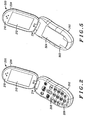
FIG. 5 is a perspective view of the handheld radiotelephone in the second open position according to the present invention of the preferred embodiment. -
FIG. 6 is a perspective view of the handheld radiotelephone in the third open position according to the present invention of the preferred embodiment. -
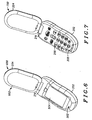
FIG. 7 is a perspective view of the handheld radiotelephone in the fourth open position according to the present invention of the preferred embodiment. -
FIG. 8 is a perspective view of the handheld radiotelephone showing the swivel motion of the first housing portion relative to the second housing portion about the second axis of the swivel hinge according to the present invention of the preferred embodiment. -
FIG. 9 is a perspective view of the handheld radiotelephone showing the folding together of the first housing portion and the second housing portion about the first axis of the swivel hinge according to the present invention of the preferred embodiment. -
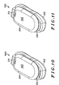
FIG. 10 is a perspective view of the handheld radiotelephone in the first closed position according to the present invention of the preferred embodiment. -
FIG. 11 is a perspective view of the handheld radiotelephone in the second closed position according to the present invention of the preferred embodiment. -
FIG. 12 is a perspective view of the handheld radiotelephone in the third closed position according to the present invention of the preferred embodiment. -
FIG. 13 is a perspective view of the handheld radiotelephone in the fourth closed position according to the present invention of the preferred embodiment. -
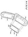
FIG. 14 is an exploded view of the handheld radiotelephone showing the detachable user interface according to the present invention of the preferred embodiment. - A handheld electronic device such as a cellular radiotelephone includes two housing portions. A first housing portion comprises at least two user interfaces and a second housing portion contains at least one user interface. The device incorporates a swivel hinge coupling the two housing portions together allowing the housing portions to rotate about a first axis such that the two housings can fold together or apart and at the same time rotate about a second axis allowing the housing portions to rotate relative to one another. This allows the multiple user interfaces of the first housing portion to rotatably align with the user interfaces of the second housing portion. Each user interface may be selectively adapted to operate in an inactive operation mode, an input operation mode, an output operation mode or a combination thereof. The user interfaces may be detachable from its associated housing portion allowing different types of user interfaces to be integrated into the electronic device. This permits an electronic device to be sold with a detachable user interface selected from plurality of user interfaces types. They may be sold separately from the electronic device itself or packaged with the device. This allows multiple combinations to be sold by packaging the device with a certain user interface. The user can easily customize the electronic device to meet that individual's need or as new types of user interfaces become available, the user may easily upgrade the electronic device by substituting the new user interface for the old thereby enhancing the product and improving its operability. The user may also want to change the mode of operation of the device by purchasing a new user interface for the device. For example, a user may want to add personal digital assistant (PDA) capability to their existing radiotelephone The PDA requires a larger display than the radiotelephone in order to view the pertinent information. Current radiotelephones require a small display as typically only a phone number and other minimal information needs to be displayed. Existing devices having this combination require complex user interfaces and large and heavy housings The present invention allows the user to easily install the new user interface with PDA operation mode capability and now the device has the additional capability of a PDA. The swivel hinge allows the user to rotate the housing portions to adapt the device to either the PDA or the radiotelephone mode. This is just but one example of mode combinations possible, other potential modes may include a wireless internet terminal, a pager, a calculator, or a hearing or vision impaired input and output device. Having multiple user interfaces in one device allows simple operation and maintains the size and weight requirements desired by the consumer.
- Turning to
FIG. 1 , a block diagram of a wireless communication device such as a cellular radiotelephone incorporating the present invention is shown. In the preferred embodiment, aframe generator ASIC 101, such as a CMOS ASIC available from Motorola, Inc. and amicroprocessor 103, such as a 68HC11 microprocessor also available from Motorola, Inc., combine to generate the necessary communication protocol for operating in a cellular system.Microprocessor 103 usesmemory 104 comprisingRAM 105,EEPROM 107, andROM 109, preferably consolidated in onepackage 111, to execute the steps necessary to generate the protocol and to perform other functions for the wireless communication device, such as reading and or writing to afirst user interface 113,second user interface 114, athird user interface 115, or afourth user interface 116, according to the present invention, or controlling afrequency synthesizer 125.ASIC 101 processes audio transformed byaudio circuitry 119 from amicrophone 117 and to aspeaker 121. - A transceiver processes the radio frequency signals. In particular, a
transmitter 123 transmits through an antenna 129 using carrier frequencies produced by afrequency synthesizer 125. Information received by the communication device's antenna 129 enters thereceiver 127 that demodulates the symbols using the carrier frequencies fromfrequency synthesizer 125. The communication device may optionally include a message receiver and storage device 130 including digital signal processing means. The message receiver and storage device could be, for example, a digital answering machine or a paging receiver. - In the present embodiment the
microprocessor 103 is used to control thefirst user interface 113,second user interface 114,third user interface 115, andfourth user interface 116. Themicroprocessor 103 may also receive input from one user interface to control the operation thereof or control the operation of another user interface. In the preferred embodiment of the present invention there are three operation modes: a first operation mode which is an inactive mode, a second operation mode which is a user input mode, and a third operation mode which is a user output mode. Thecontroller 103 can control the appropriate user interface to enter a desired operation mode or combination thereof based on the position of the first housing portion relative to the second housing portion or based on user input commands. The microprocessor may further receive signals from afirst position sensor 133 indicating whether the housing is in the open or closed position or asecond position sensor 135 indicating the rotation position of thefirst housing portion 202 relative to thesecond housing portion 204. - Turning to
FIGs. 2 to 7 , the handheldelectronic device 100 has two housing portions, afirst housing portion 202 and asecond housing portion 204. Each housing portion has at least two faces. The face of the housing portion is a substantially flat surface that is large enough to accommodate some form of user interface. In the preferred embodiment of the present invention, each housing portion has a pair of opposing faces; thefirst housing portion 202 has afirst face 206 and asecond face 502, and thesecond housing portion 204 has athird face 210 and afourth face 602. Mounted within thefirst housing portion 202 and accessible on thefirst face 206 is afirst user interface 208. Asecond user interface 504 is also mounted within thefirst housing portion 204 and accessible on thesecond face 502. Athird user interface 212 is mounted within thesecond housing portion 202 and accessible from thethird face 210. In addition, a fourth user interface (not shown) may be added to thesecond housing portion 204, accessible on thefourth face 602 of thesecond housing portion 204. - The housing portions are coupled end to end by a
swivel hinge 214 depicted inFIGs. 3 and 4 . The swivel hinge allows thefirst housing portion 202 and thesecond housing portion 204 to fold together in a clam shell fashion, rotating about afirst axis 302 theswivel hinge 214. This rotation about thefirst axis 302 of theswivel hinge 214 is shown inFIG. 9 . Thefirst axis 302 allows thesecond housing portion 204 to rotate from a closed position to an open position. In the closed position, thefirst housing portion 202 and thesecond housing portion 204 are planarly adjacent such that the device is folded in half. In the open position thefirst housing portion 202 is angularly displaced at an angel between 90 and 180 degrees. - Also shown in
FIGs. 3 and 4 is aflex circuit 306 that electrically connects a first electronic portion in the first housing portion and a second electronic portion in the second housing portion and is routed through theswivel hinge 214. Theflex circuit 306 is extremely malleable allowing it to bend and flex and maintain continuous continuity while the shape of theflex circuit 306 allows it to fit within theswivel hinge 214. A constant electrical connection between the first electronic portion and the second electronic portion can therefore be maintained during the swiveling from position to position of the first and second housing portions.FIG. 3 shows the flex circuit outside of theswivel hinge 214 whileFIG. 4 shows the flex circuit inside theswivel hinge 214. - A
second axis 304 of theswivel hinge 214 allows thefirst housing portion 202 to advantageously rotate relative to thesecond housing portion 204 in a swiveling motion as shown inFIG. 8 . This allows thefirst housing portion 202 to adaptably rotate to a first housing portion first rotation position, and a first housing portion second rotation position relative to saidsecond housing portion 204. This advantageously allows one device to have multiple user interfaces within the two housing portions and further allows the user to align the user interfaces in multiple combinations giving the device increased functionality as each interface provides a different mode of operation without increasing the complexity of the device. Theswivel hinge 214 further allows thesecond housing portion 204 to rotate from a second housing portion first rotation position to a second housing portion second rotation position, relative to thefirst housing portion 202. - The combination of the
first axis 302 with thesecond axis 304 into one coupling is highly beneficial as it allows a plurality of user interface combinations. For example, in the preferred embodiment of the present invention thefirst housing portion 202 in the first housing portion first rotation position and the second housing portion in the second housing portion first rotation position, aligns thefirst user interface 208 with thethird user interface 212 while the device is in a closed or open position. In a first closed position, Shown inFIG. 10 , with this user interface alignment, thefirst user interface 208 is adjacent to thethird user interface 212 and enclosed between thefirst housing portion 202 and thesecond housing portion 204. In this position, bothuser interfaces - However, the device itself could still be powered on and in a monitoring mode. Depending on the device mode, it may be waiting for an incoming signal. If the device is a radiotelephone, as in the preferred embodiment of the present invention, the device would monitor the cellular telephone system for incoming call signals. If the device is a PDA, data transmissions in the form of web pages or other information of the like may be received. In the first closed position
FIG. 10 the first user interface and the third user interface would be protected between the two housing portions while the device remains powered on. When an incoming phone call is received and the user alerted to the call, the device may be unfolded by rotating the two housing portions apart about thefirst axis 302 to the first open position,FIG. 2 so that the first housing portion and the second housing portion are angularly displaced. This is considered the normally closed position and is therefore used when the device is not in use protecting the user interfaces from damage. - While in the first open position
FIG. 2 , having the first housing portioned 202 in the first housing portion first rotation position and thesecond housing portion 204 in the second housing portion first rotation position, thesecond housing portion 204 may be rotated, relative to thefirst housing portion 202, to the second housing portion second rotation position putting the housing in the third open positionFIG. 6 . Subsequently, from the third open positionFIG. 6 , the device may be folded into a third closed position as shown inFIG. 13 . In the third closed positionFIG. 13 , thefirst user interface 208 is enclosed between thefirst housing portion 202 and thesecond housing portion 204, while thethird user interface 212 is on the outside of the device accessible to the user. - In the third closed position
FIG. 13 , the first user interface may extend beyond thesecond housing portion 204 such that a third closed positionaccessible portion 1302 of the first user interface is accessible to the user. The combination of the third closed positionaccessible portion 1302 and the exposedthird user interface 212 allows the user to affect the operation of thethird user interface 212 by the third closed positionaccessible portion 1302 of thefirst user interface 208. - The present invention may further be rotated to a fourth open position shown in
FIG. 7 . In the fourth open positionFIG. 7 , having the first housing portioned 202 in the first housing portion second rotation position and thesecond housing portion 204 in the second housing portion second rotation position, thesecond housing portion 204 may be folded into a fourth closed position as shown inFIG. 12 . In the fourth closed positionFIG. 12 , thesecond user interface 504 is enclosed between thefirst housing portion 202 and thesecond housing portion 204, while thethird user interface 212 is on the outside of the device accessible to the user. - In the fourth closed position
FIG. 12 , thesecond user interface 504 may extend beyond thesecond housing portion 204 such that a fourth closed positionaccessible portion 1302 of thesecond user interface 504 is accessible to the user. The combination of the fourth closed positionaccessible portion 1302 and the exposedthird user interface 212 allows the user to affect the operation of the third user interface by the fourth closed positionaccessible portion 1302 of thesecond user interface 212. The fourth closed positionaccessible portion 1302 may include navigation buttons for web page control or menu navigation, or a power button to turn the device on or off, or other buttons of the like. - When rotating the device from position to position detectors mounted within the first housing portion and coupled to the
microprocessor 103, provide housing position information thereto. In the case of the preferred embodiment of the present invention, the detector is a reed switch. The reed switch is closed, therefor completing the circuit when a magnet is place adjacent thereto. A first detector 228 is located in thefirst housing portion 202 at the end longitudinally opposite theswivel hinge 214. A first magnet 222 is located in thesecond housing portion 204, longitudinally opposite theswivel hinge 214 and aligned with the first detector 228 such that the first magnet 222 becomes substantially adjacent to the first detector 228 when the housing is rotated to the first, second, third or fourth closed positionsFIG. 10, FIG. 11 ,FIG. 12, FIG. 13 respectively. In response to the magnet activating the first detector, a first position signal is sent to themicroprocessor 103. Based on the first position signal themicroprocessor 103 sends a signal to the appropriate user interface in accordance with the programmed operation mode of the device. - Further comprised in the preferred embodiment of the present invention is a second detector 226. The second detector 226 is located in the
first housing portion 202 along the first axis of theswivel hinge 214. A second magnet 224 is located in thesecond housing portion 204, such that when thesecond housing portion 204 is in the second housing portion first rotation position, the second magnet 224 aligns with the second detector 228. The close proximity of the second magnet 224 to the second detector 228 activates the second detector 228 providing a second position signal to themicroprocessor 103. Based on the second position signal and the first position signal, themicroprocessor 103 sends a operating mode signal to the appropriate user interface in accordance with the programmed operation modes available in the device. - Even Further, the preferred embodiment of the present invention incorporates a
detachable user interface 1400 as shown inFIG. 14 . In the case of the present invention, the detachable user interface serves two purposes: auser interface 1402 of multiple types and modes, and abattery door 1404 for coupling to thefirst housing portion 202. The battery door is secured to thefirst housing portion 202 bylatch 1406. Theuser interface 1402 mounted within the battery door is coupled to a first interconnect means 1208 located on the opposite side of thedetachable user interface 1400. The first interconnect means 1208 aligns with a second interconnect means 1210 mounted to thefirst housing portion 202 such that when the detachable user interface is secured to thefirst housing portion 202 the first interconnect means makes electrical contact with the second interconnect means. This provides multiple electrical links from theuser interface 1402 of thedetachable user interface 1400 to themicroprocessor 103 for control thereof. - Having multiple user interfaces allows for multiple modes of operation within a single handheld device. The detachable user interface further allows the manufacture to easily market devices with in a plurality of combinations. For instance one device can be manufactured and then simply packag4ed with a detachable user interface that is directed to a certain consumer. This significantly reduces the cost to the manufacture by postponing the customization of the device until the packaging stage. The device itself must only necessarily be manufactured to accommodate the different detachable user interfaces. The detachable user interface can now be manufactured to accommodate smaller consumer markets such as providing access to the disabled. User interfaces may easily be manufactured to accommodate the vision and hearing impaired and either sold separately or combined with the product in the packaging stage.
- For example, vision impaired output device may include a Braille output device or a display that has very large fonts and icons that are easily identifiable. Another example may be to increase the button size which could accommodate both vision impaired and the dexterity impaired. User interfaces that accommodate hearing impaired may also be adapted to the detachable user interface. Examples include an enhanced loudspeaker, TTY, or more visual icons and cues to alert the user.
- Even Further a detachable user interface may be a touch pad, full-text mini keyboard, remote control unit for home audio. The device may also be an output device to operate in conjunction with the third user interface. In the preferred embodiment of the present invention incorporates a detachable user interface into the batter door. Removing the detachable user interface allows for replacement of the battery pack.
- Although the invention has been described and illustrated in the above description and drawings, it is understood that this description is by way of example only and that numerous changes and modifications can me made by those skilled in the art without departing from the scope of the invention. For example, although one device includes three user interfaces, more may be included. The invention is not limited by the type of user interface and may include other types that the user desires Although the present invention finds particular use in portable cellular radiotelephones, the invention could be applied to any wireless communication device, including pagers, electronic organizers, and computers as well. Applicant's invention should be limited only by the following claims.
- We Claim:
Claims (9)
- A handheld radiotelephone comprising:a housing having a first housing portion (202) and a second
housing portion (204), said first housing portion having a first and second face (206, 502), and said second housing portion having a third and fourth face (210, 602);a first user interface (208) mounted within said first
housing portion and accessible on said first face (206);a third user interface (212) mounted within said second
housing portion and accessible on said third face (210); anda hinge (214) for coupling said first housing portion (202)
to said second housing portion (204) such that said first housing portion and said second housing portion rotate about a first axis (302) of said hinge (214) and wherein said hinge further couples said first housing portion and said second housing portion such that said first and said second housing portions rotate about a second axis (304) of said hinge perpendicular to said first axis,wherein said first housing portion and said second housing
portion are rotatable to a first closed position (1000) wherein the first face (206) of said first housing portion is planarly adjacent to the third face (210) of said second housing portion and,wherein said first housing portion and said second housing
portion are rotatable to a second closed position wherein said second face (502) of the first housing portion is planarly adjacent to the third face (210) of said second housing portion;the handheld radiotelephone being characterised by:a second user interface (504) mounted within said first
housing portion and accessible on said second face (502), wherein the first, second and third user interfaces are arranged to enable the device to operate in a plurality of operation modes, a desired operation mode being user selectable by rotating either of the first and second housing portions to a position associated with the desired operation modewherein said first housing portion and said second housing
portion are rotatable to a third closed position wherein the first face (206) of said first housing portion is planarly adjacent to said fourth face (602) of said second housing portion, andwherein said first housing portion and said second housing
portion are rotatable to a fourth closed position wherein said second face (502) of said first housing portion is planarly adjacent to said fourth face (602) of said second housing portion. - The handheld radiotelephone of claim 1,
wherein said first housing portion and said second housing
portion are rotatable to a first open position (200) wherein the first face (206) of said first housing portion is angularly displaced from the third face (210) of said second housing portion and,
wherein said first housing portion and said second housing
portion are rotatable to a second open position wherein
said second face (502) of the first housing portion is angularly displaced from the third face (210) of said second housing portion;
wherein said first housing portion and said second housing
portion are rotatable to a third open position wherein the first face (206) of said first housing portion is angularly displaced from said fourth face (602) of said second housing portion, and
wherein said first housing portion and said second housing
portion are rotatable to a fourth open position wherein said second face (502) of said first housing portion is angularly displaced from said fourth face (602) of said second housing portion. - The handheld radiotelephone according to claim 1 or 2,
wherein said second housing portion partially covers said first user interface in said first and said third closed position to define a first closed position accessible portion (1202) and a third closed accessible portion (1302) thereof and a first closed position inaccessible portion and a third closed position inaccessible portion thereof, and wherein said second housing portion partially covers said second user interface in said second and said fourth closed position to define a second closed position accessible portion and a fourth closed position accessible portion and a second closed position inaccessible portion and a fourth closed position inaccessible portion. - The handheld radiotelephone according to claim 3, wherein said first accessible portion (1202) of said first user interface of said housing in said first closed position is in an input operation mode, output operation mode or combination thereof and said inaccessible portion is in an inactive mode and said second user interface is in said input operation mode, said output operation mode, or a combination thereof, and
wherein said first accessible portion of said first user
interface of said housing in said first open position is in an input operation mode, output operation mode or combination thereof, and said inaccessible portion is in an input operation mode, output operation mode or combination thereof and said second user interface is in said input operation mode, said output operation mode, or a combination thereof. - The handheld radiotelephone according to any preceding claim, further comprising a controller (103) coupled to said first user interface (208), said second user interface (504), and said third user interface (212), for generating and providing an operation mode signal therefore for control thereof in an inactive mode, an input operation mode or an output operation mode.
- The handheld radiotelephone according to claim 5,
wherein said controller (103) receives a user selectable
operating mode selection signal generated by said first user interface (208), second user interface (504), or third user interface (212) to define the operating mode of said first, said second, or said third user interface. - The handheld radiotelephone according to claim 5 or 6, further comprising:a first position detector (133) for generating a first position signal for indicating whether the housings are in an open or closed position and coupled to said controller (103) for providing said first position signal thereto, anda second position detector (135) for generating a second position signal for indicating the rotation position of the first housing portion (202) relative to the second housing portion (204) about the second axis (304), and coupled to said controller (103) for providing said second position signal thereto.
- The handheld radiotelephone according to any preceding claim, further comprising a fourth user interface mounted within said second housing portion accessible on said fourth face (602).
- The handheld radio telephone according to any preceding claim wherein one or more of said first user interface (208), said second user interface (504), and said third user interface (212) is attachably removable from its associated housing portion and wherein its associated housing portion is adapted to accommodate different attachably removable user interfaces.
Priority Applications (1)
| Application Number | Priority Date | Filing Date | Title |
|---|---|---|---|
| EP07003733A EP1804470A3 (en) | 2000-04-28 | 2001-04-24 | Portable electronic device with an adaptable user interface |
Applications Claiming Priority (3)
| Application Number | Priority Date | Filing Date | Title |
|---|---|---|---|
| US560767 | 2000-04-28 | ||
| US09/560,767 US6549789B1 (en) | 2000-04-28 | 2000-04-28 | Portable electronic device with an adaptable user interface |
| PCT/US2001/013262 WO2001084729A1 (en) | 2000-04-28 | 2001-04-24 | Portable electronic device with an adaptable user interface |
Related Child Applications (2)
| Application Number | Title | Priority Date | Filing Date |
|---|---|---|---|
| EP07003733A Division EP1804470A3 (en) | 2000-04-28 | 2001-04-24 | Portable electronic device with an adaptable user interface |
| EP07003733.8 Division-Into | 2007-02-23 |
Publications (3)
| Publication Number | Publication Date |
|---|---|
| EP1293046A1 EP1293046A1 (en) | 2003-03-19 |
| EP1293046A4 EP1293046A4 (en) | 2004-04-14 |
| EP1293046B1 true EP1293046B1 (en) | 2011-08-03 |
Family
ID=24239279
Family Applications (2)
| Application Number | Title | Priority Date | Filing Date |
|---|---|---|---|
| EP01930729A Expired - Lifetime EP1293046B1 (en) | 2000-04-28 | 2001-04-24 | Portable electronic device with an adaptable user interface |
| EP07003733A Withdrawn EP1804470A3 (en) | 2000-04-28 | 2001-04-24 | Portable electronic device with an adaptable user interface |
Family Applications After (1)
| Application Number | Title | Priority Date | Filing Date |
|---|---|---|---|
| EP07003733A Withdrawn EP1804470A3 (en) | 2000-04-28 | 2001-04-24 | Portable electronic device with an adaptable user interface |
Country Status (9)
| Country | Link |
|---|---|
| US (1) | US6549789B1 (en) |
| EP (2) | EP1293046B1 (en) |
| JP (1) | JP2003533090A (en) |
| KR (1) | KR100507820B1 (en) |
| CN (1) | CN1241331C (en) |
| AT (1) | ATE519324T1 (en) |
| AU (1) | AU2001257235A1 (en) |
| ES (1) | ES2367418T3 (en) |
| WO (1) | WO2001084729A1 (en) |
Families Citing this family (195)
| Publication number | Priority date | Publication date | Assignee | Title |
|---|---|---|---|---|
| US7491861B2 (en) * | 2002-07-31 | 2009-02-17 | Studsvik, Inc. | In-drum pyrolysis |
| FI19992510A (en) * | 1999-11-24 | 2001-05-25 | Nokia Mobile Phones Ltd | Electronic device and method in the electronic device |
| JP2001236138A (en) * | 2000-02-22 | 2001-08-31 | Sony Corp | Communication terminal |
| KR100460105B1 (en) * | 2000-02-22 | 2004-12-03 | 엘지전자 주식회사 | Method for searching a menu in a mobile communication terminal |
| JP2001268613A (en) * | 2000-03-15 | 2001-09-28 | Sony Corp | Portable information terminal |
| JP4385490B2 (en) * | 2000-05-12 | 2009-12-16 | ソニー株式会社 | Mobile terminal device |
| US6952676B2 (en) * | 2000-07-11 | 2005-10-04 | Sherman William F | Voice recognition peripheral device |
| JP3542955B2 (en) * | 2000-10-11 | 2004-07-14 | 埼玉日本電気株式会社 | Mobile phone |
| JP2002158758A (en) * | 2000-11-20 | 2002-05-31 | Nec Corp | Opening/closing type portable information terminal |
| US6850784B2 (en) * | 2001-01-31 | 2005-02-01 | Microsoft Corporation | Modular two-body design for integration of mobile computing device features with a wireless communication device |
| US6834199B2 (en) * | 2001-03-19 | 2004-12-21 | Samsung Electronics Co., Ltd. | Portable telephone with an exchangeable data input apparatus |
| US7077841B2 (en) | 2001-03-26 | 2006-07-18 | Curon Medical, Inc. | Systems and methods employing a guidewire for positioning and stabilizing external instruments deployed within the body |
| US7173665B2 (en) * | 2001-03-30 | 2007-02-06 | Sanyo Electric Co., Ltd. | Folding mobile communication terminal |
| US6768899B2 (en) * | 2001-04-04 | 2004-07-27 | Motorola, Inc. | Rotational mechanism for a wireless communication device |
| US6920338B2 (en) * | 2001-05-17 | 2005-07-19 | Wildseed, Ltd. | Adding I/O ports to mobile device via smart interchangeable cover |
| US7079864B2 (en) * | 2001-05-17 | 2006-07-18 | Wildseed, Ltd. | Adding peripheral devices to mobile devices via smart interchangeable cover |
| US20030104791A1 (en) * | 2001-05-17 | 2003-06-05 | Engstrom G. Eric | Adding peripherals to mobile device via smart interchangeable cover |
| US20030073462A1 (en) * | 2001-05-17 | 2003-04-17 | Peter Zatloukal | Adding control keys to mobile device via smart interchangeable cover |
| US7054440B2 (en) * | 2001-05-23 | 2006-05-30 | Telefonaktiebolaget Lm Ericsson (Publ) | Method and apparatus for keypad representation in a mobile communication device |
| ITMI20011163A1 (en) * | 2001-05-31 | 2002-12-01 | Gianni Salpietra | TELEPHONE FOR THE BLIND |
| FI20015005A (en) * | 2001-05-31 | 2002-12-01 | Nokia Corp | A mobile station comprising a display element |
| US20040127262A1 (en) * | 2001-05-31 | 2004-07-01 | Yoshiharu Ohno | Cellular telephone |
| JP2002368850A (en) * | 2001-06-05 | 2002-12-20 | Sony Corp | Portable wireless terminal |
| KR100382938B1 (en) | 2001-06-21 | 2003-05-09 | 엘지전자 주식회사 | Folder type mobile phone added sub-display |
| KR100470172B1 (en) * | 2001-06-22 | 2005-02-04 | 주식회사 임팩트라 | Mobile Station having Display Part Convertible Vertical into Horizontal |
| JP2003008695A (en) * | 2001-06-25 | 2003-01-10 | Pioneer Electronic Corp | Personal digital assistant |
| KR100438433B1 (en) * | 2001-06-26 | 2004-07-03 | 삼성전자주식회사 | Combination device with portable radiotelephone/personal digital assistant/digital camera assembly |
| CN1177453C (en) * | 2001-07-19 | 2004-11-24 | 朱占新 | Mobile phone set with rotatable display screen |
| US7006853B2 (en) * | 2001-08-24 | 2006-02-28 | Samsung Electronics Co., Ltd. | Rotary type hinge module for portable wireless terminal |
| US7729698B2 (en) * | 2001-09-27 | 2010-06-01 | Qualcomm Incorporated | Communication system receiver and method for concurrent receiving of multiple channels |
| JP2003174495A (en) * | 2001-09-28 | 2003-06-20 | Nec Corp | Folding portable information terminal |
| US6999062B2 (en) * | 2001-10-09 | 2006-02-14 | Sony Corporation | Dual electro-luminance back light remote commander and method |
| US7881743B2 (en) * | 2001-10-16 | 2011-02-01 | Research In Motion Limited | Handheld mobile communication device |
| US9755314B2 (en) | 2001-10-16 | 2017-09-05 | Fractus S.A. | Loaded antenna |
| JP2003120653A (en) * | 2001-10-17 | 2003-04-23 | Ohashi Technica Inc | Hinge device and cellular phone using this hinge device |
| US6934518B2 (en) * | 2001-11-05 | 2005-08-23 | Quanta Computer Inc. | Mobile phone with a hidden input device |
| JP2003152840A (en) * | 2001-11-13 | 2003-05-23 | Nec Corp | Mobile phone |
| KR100421370B1 (en) * | 2001-11-16 | 2004-03-06 | 엘지전자 주식회사 | Fpc connecting structure for electronic equipment and fpc thereof |
| JP3648476B2 (en) * | 2001-11-30 | 2005-05-18 | 株式会社東芝 | Portable information equipment |
| KR100486611B1 (en) | 2001-12-18 | 2005-05-03 | 주식회사 팬택앤큐리텔 | A personal mobile telephone haivng a LCD apparatus being capable of rotating |
| EP1324571A3 (en) * | 2001-12-28 | 2004-12-15 | Matsushita Electric Industrial Co., Ltd. | Mobile terminal device |
| US20030142471A1 (en) * | 2002-01-29 | 2003-07-31 | Palm, Inc. | Replaceable cover for handheld computer |
| US6781824B2 (en) * | 2002-01-29 | 2004-08-24 | Palm, Inc. | Encasement for handheld computer |
| WO2003075475A1 (en) * | 2002-03-02 | 2003-09-12 | M2Sys Co., Ltd. | Rotary hinge mechanism of portable phone |
| JP4019750B2 (en) * | 2002-03-06 | 2007-12-12 | 日本電気株式会社 | Foldable portable information terminal, response hold method used therefor, and program thereof |
| JP4309091B2 (en) * | 2002-03-06 | 2009-08-05 | 日本電気株式会社 | Foldable portable information terminal, status notification method used therefor, and program thereof |
| US7289627B2 (en) * | 2002-03-19 | 2007-10-30 | Matsushita Electric Industrial Co., Ltd. | Hinge, and opening/closing type portable terminal device having the same |
| JP4063571B2 (en) * | 2002-04-10 | 2008-03-19 | 日本電気株式会社 | Foldable mobile communication terminal |
| KR100461180B1 (en) * | 2002-04-12 | 2004-12-13 | 삼성전자주식회사 | Portable Computer |
| DE10219404B4 (en) * | 2002-04-30 | 2005-06-02 | Siemens Ag | Foldable information technology device |
| US7257430B2 (en) * | 2002-05-11 | 2007-08-14 | Motorola, Inc. | Self configuring multiple element portable electronic device |
| US6728557B1 (en) * | 2002-05-17 | 2004-04-27 | Motorola, Inc. | Hinge assembly for a multi-configuration portable electronic device |
| US20030222846A1 (en) * | 2002-05-31 | 2003-12-04 | Huy Nguyen | Multi-functional handheld device having moveable segments |
| US6856506B2 (en) * | 2002-06-19 | 2005-02-15 | Motion Computing | Tablet computing device with three-dimensional docking support |
| US8060167B2 (en) * | 2002-07-19 | 2011-11-15 | Panasonic Corporation | Portable wireless machine |
| US7773957B2 (en) * | 2002-07-22 | 2010-08-10 | Samsung Electronics Co., Ltd | Mobile communication terminal with rotational display unit |
| KR20040011275A (en) * | 2002-07-30 | 2004-02-05 | 엘지전자 주식회사 | Structure of camera in portable image phone |
| US7184718B2 (en) * | 2002-07-30 | 2007-02-27 | Nokia Corporation | Transformable mobile station |
| JP3941933B2 (en) * | 2002-08-26 | 2007-07-11 | 松下電器産業株式会社 | Opening and closing communication terminal and hinge device |
| EP1403753A3 (en) * | 2002-09-25 | 2006-11-29 | Sharp Kabushiki Kaisha | Electronic appliance |
| JP3999092B2 (en) * | 2002-09-30 | 2007-10-31 | 京セラ株式会社 | Stackable mobile terminal device |
| JP2004343677A (en) * | 2002-10-02 | 2004-12-02 | Nec Saitama Ltd | Mobile phone, its auto dialing lock method, and program |
| JP2004134975A (en) | 2002-10-09 | 2004-04-30 | Matsushita Electric Ind Co Ltd | Communication terminal |
| JP2004134976A (en) * | 2002-10-09 | 2004-04-30 | Matsushita Electric Ind Co Ltd | Communication terminal |
| KR100810300B1 (en) | 2002-10-15 | 2008-03-06 | 삼성전자주식회사 | Portable communication device |
| TW551787U (en) * | 2002-10-21 | 2003-09-01 | Wistron Corp | Electronic equipment having rotation positioning device |
| US7565182B2 (en) * | 2002-10-22 | 2009-07-21 | Samsung Electronics Co., Ltd. | Wireless cell phone |
| US6830456B2 (en) * | 2002-10-28 | 2004-12-14 | Hewlett-Packard Development Company, L.P. | Connector and apparatus including the same |
| JP3961397B2 (en) * | 2002-10-29 | 2007-08-22 | 京セラ株式会社 | Mobile terminal device |
| KR101004300B1 (en) * | 2002-11-20 | 2010-12-28 | 파나소닉 주식회사 | Portable communication terminal |
| WO2004049150A2 (en) | 2002-11-21 | 2004-06-10 | Danger, Inc. | Data processing device with adjuntable display and input devices with multiple orientations |
| JP4238571B2 (en) * | 2002-12-06 | 2009-03-18 | 日本電気株式会社 | Foldable portable device, its wiring device and wiring method |
| US7117009B2 (en) * | 2002-12-20 | 2006-10-03 | Motorola, Inc. | Apparatus and method for electronic device control |
| ES2380576T3 (en) * | 2002-12-22 | 2012-05-16 | Fractus, S.A. | Unipolar multiband antenna for a mobile communications device |
| KR100841306B1 (en) * | 2002-12-26 | 2008-06-26 | 엘지전자 주식회사 | Mobile telecommunication terminal having multiple display |
| US6839576B2 (en) * | 2002-12-30 | 2005-01-04 | Motorola, Inc. | Multiple axis hinge assembly |
| EP1435724A1 (en) * | 2002-12-30 | 2004-07-07 | Motorola, Inc. | Housing |
| US6856792B2 (en) * | 2002-12-30 | 2005-02-15 | Motorola, Inc. | Self operating opening mechanism for use in a hand-held electronic device |
| US7031759B2 (en) * | 2002-12-30 | 2006-04-18 | Motorola, Inc. | Rotating user interface |
| US7269255B2 (en) * | 2003-02-12 | 2007-09-11 | Matsushita Electric Industrial Co., Ltd. | Portable terminal device |
| US6798646B2 (en) * | 2003-02-14 | 2004-09-28 | Lite-On Technology Corporation | Rotary axle structure for portable computers |
| KR20040079203A (en) * | 2003-03-06 | 2004-09-14 | 삼성전자주식회사 | Portable communication device |
| KR100463777B1 (en) * | 2003-03-11 | 2004-12-29 | 삼성전자주식회사 | Bar type portable wireless terminal and rotary type hinge device thereof |
| US20040192220A1 (en) * | 2003-03-24 | 2004-09-30 | Inventec Appliances Corp. | Mechanism for switching cellular phone to digital camera |
| FI118668B (en) * | 2003-04-01 | 2008-01-31 | Samsung Electro Mech | Mobile phone and its automatic rotation method |
| JP4010975B2 (en) * | 2003-04-07 | 2007-11-21 | ソニー・エリクソン・モバイルコミュニケーションズ株式会社 | Mobile communication terminal device |
| KR100513015B1 (en) * | 2003-04-08 | 2005-09-05 | 삼성전자주식회사 | Rotary type hinge device for portable wireless terminal |
| JP2004312476A (en) * | 2003-04-09 | 2004-11-04 | Nec Corp | Foldable portable information terminal |
| JP2004310659A (en) * | 2003-04-10 | 2004-11-04 | Matsushita Electric Ind Co Ltd | Information processor |
| JP2004320375A (en) * | 2003-04-15 | 2004-11-11 | Sony Ericsson Mobilecommunications Japan Inc | Electronic apparatus |
| JP2004336091A (en) * | 2003-04-30 | 2004-11-25 | Nec Corp | Foldable mobile communication apparatus |
| KR101018375B1 (en) | 2003-05-06 | 2011-03-02 | 삼성전자주식회사 | Hinge device and electric cable being used for same |
| JP4297725B2 (en) * | 2003-05-07 | 2009-07-15 | スガツネ工業株式会社 | Portable device and hinge device |
| US7475452B2 (en) * | 2003-05-21 | 2009-01-13 | Premier Image Technology Corporation | Swivel structure for information product |
| ATE333749T1 (en) * | 2003-05-21 | 2006-08-15 | Sony Ericsson Mobile Comm Ab | FOLDABLE MOBILE TERMINAL WITH A FLEXIBLE DISPLAY UNIT |
| EP1496673B1 (en) * | 2003-07-11 | 2014-09-10 | LG Electronics Inc. | Swivel hinge and portable terminal using the same |
| US7450977B2 (en) * | 2003-07-31 | 2008-11-11 | Vodafone K.K. | Mobile communication terminal |
| JP2005054890A (en) * | 2003-08-04 | 2005-03-03 | Kato Electrical Mach Co Ltd | Hinge for portable terminal |
| US7506152B2 (en) | 2003-08-11 | 2009-03-17 | Lg Electronics Inc. | Convertible computer with selective loading of an operating system based on a tablet or notebook mode |
| TWM243896U (en) * | 2003-08-15 | 2004-09-11 | Hon Hai Prec Ind Co Ltd | Repalceable panel for handset |
| KR100563724B1 (en) * | 2003-08-22 | 2006-03-28 | 엘지전자 주식회사 | Two way rotation hinge module having folder type mobile phone |
| JP2005078316A (en) * | 2003-08-29 | 2005-03-24 | Kyocera Corp | Portable terminal device |
| KR100979108B1 (en) | 2003-09-08 | 2010-08-31 | 엘지전자 주식회사 | Apparatus and method for controlling power supply in convertible computer |
| JP2005191832A (en) * | 2003-12-25 | 2005-07-14 | Fujitsu Ltd | Cell phone |
| US7636748B2 (en) | 2003-09-29 | 2009-12-22 | Microsoft Corporation | Display configurations for a data processing device |
| US7280346B2 (en) * | 2003-09-29 | 2007-10-09 | Danger, Inc. | Adjustable display for a data processing apparatus |
| TWI267334B (en) * | 2003-09-29 | 2006-11-21 | Benq Corp | Hand-held electronic apparatus |
| JP2005107840A (en) * | 2003-09-30 | 2005-04-21 | Toshiba Corp | Electronic appliance |
| US7342806B2 (en) * | 2003-10-14 | 2008-03-11 | Sony Ericsson Mobile Communications Ab | Portable electronic device with multiple input interfaces |
| KR100566276B1 (en) * | 2003-10-17 | 2006-03-30 | 삼성전자주식회사 | Portable terminal and swing hinge module thereof |
| US7236356B2 (en) | 2003-10-22 | 2007-06-26 | Motion Computing, Inc. | External battery pack |
| US20050091431A1 (en) * | 2003-10-23 | 2005-04-28 | Robert Olodort | Portable communication devices |
| US20050125570A1 (en) * | 2003-10-23 | 2005-06-09 | Robert Olodort | Portable communication devices |
| JP4113092B2 (en) * | 2003-10-24 | 2008-07-02 | 三菱製鋼株式会社 | Biaxial hinge rotation mechanism and mobile phone equipped with the same |
| US7532915B2 (en) * | 2003-11-03 | 2009-05-12 | Agere Systems Inc. | Electronic apparatus having three modes of operation |
| KR100677300B1 (en) * | 2003-11-21 | 2007-02-05 | 엘지전자 주식회사 | Mobile device |
| KR100575752B1 (en) * | 2003-11-27 | 2006-05-03 | 엘지전자 주식회사 | Apparatus and method control speaker for communication of mobile station |
| KR100608731B1 (en) | 2003-12-22 | 2006-08-04 | 엘지전자 주식회사 | Swible mobile phone and communicating method using the same |
| GB2409497B (en) * | 2003-12-23 | 2007-06-20 | Nokia Corp | Modular hinge for handheld electronic devices |
| US7274746B2 (en) * | 2003-12-24 | 2007-09-25 | Spirent Communications Of Rockville, Inc. | System and method for mitigating noise associated with information communication |
| US20050150080A1 (en) * | 2004-01-12 | 2005-07-14 | Shin Zu Shing Co., Ltd. | Dual-directional hinge for a mobile phone |
| EP1709704A2 (en) | 2004-01-30 | 2006-10-11 | Fractus, S.A. | Multi-band monopole antennas for mobile communications devices |
| JP4102768B2 (en) * | 2004-02-06 | 2008-06-18 | 埼玉日本電気株式会社 | Portable information terminal device |
| US7330547B2 (en) * | 2004-02-26 | 2008-02-12 | Nokia Corporation | Dual keypad phone |
| US20050192066A1 (en) * | 2004-02-26 | 2005-09-01 | Samsung Electronics Co., Ltd. | Portable communication apparatus having triple-axis hinge folder and rotation locking device thereof |
| US20050193524A1 (en) * | 2004-03-05 | 2005-09-08 | First International Computer Inc. | Pivot structure for a foldable product |
| JP4552463B2 (en) * | 2004-03-08 | 2010-09-29 | 日本電気株式会社 | Mobile device |
| JP2005286610A (en) * | 2004-03-29 | 2005-10-13 | Nec Corp | Collapsible portable telephone |
| US20050245294A1 (en) * | 2004-03-30 | 2005-11-03 | Amphenol-T&M Antennas. | Dual axis hinge for handheld device |
| EP1735995A1 (en) * | 2004-04-05 | 2006-12-27 | Nokia Corporation | An electronic imaging device |
| KR20050100154A (en) * | 2004-04-13 | 2005-10-18 | 주식회사 팬택앤큐리텔 | Mobile communication terminal easy to take a photograph using digital camera |
| TWM255633U (en) * | 2004-04-23 | 2005-01-11 | Inventec Corp | Portable electronic device |
| US6976861B2 (en) * | 2004-04-26 | 2005-12-20 | Motorola, Inc. | Handheld electronics device having pivotal hinge mechanism |
| KR100630067B1 (en) * | 2004-04-29 | 2006-09-27 | 삼성전자주식회사 | Dual hinge type portable communication device with pda |
| JP2005341027A (en) | 2004-05-25 | 2005-12-08 | Nec Saitama Ltd | Mobile communication terminal and forming method thereof |
| FI20045210A (en) * | 2004-06-04 | 2005-12-05 | Nokia Corp | Electronic device and method for providing the structure of the electronic device for various modes of use |
| JP2005354384A (en) * | 2004-06-10 | 2005-12-22 | Nec Saitama Ltd | Mechanism and method for detecting opening and closing of foldable mobile terminal device |
| US20080055829A1 (en) * | 2004-06-26 | 2008-03-06 | M2Sys Co., Ltd. | Display Swing Mechanism of Portable Terminal |
| US20060003818A1 (en) * | 2004-06-30 | 2006-01-05 | Jacob Navntoft | Hinge lock |
| JP4286735B2 (en) * | 2004-07-08 | 2009-07-01 | シャープ株式会社 | Portable device |
| US20060046792A1 (en) * | 2004-08-31 | 2006-03-02 | Hassemer Brian J | Hinge apparatus and methods therefor |
| JP4510024B2 (en) * | 2004-09-07 | 2010-07-21 | パイオニア株式会社 | Electronics |
| EP1792470A1 (en) * | 2004-09-20 | 2007-06-06 | Nokia Corporation | Foldable cellular phone device |
| US7565183B2 (en) * | 2004-11-15 | 2009-07-21 | Sony Ericsson Mobile Communications Ab | Mobile device with selectable camera position |
| KR100672513B1 (en) * | 2004-11-19 | 2007-01-24 | 엘지전자 주식회사 | Bar type mobile communication device |
| US7580518B2 (en) * | 2004-12-01 | 2009-08-25 | Motorola, Inc. | Dual-axes hinge part for hinged components |
| US20060121852A1 (en) * | 2004-12-03 | 2006-06-08 | Samsung Electronics Co., Ltd. | Portable apparatus |
| US7136687B2 (en) * | 2004-12-16 | 2006-11-14 | Chi Mei Communication Systems, Inc. | Electrical device for adjusting the angle between a top module and a bottom module |
| US20060135226A1 (en) * | 2004-12-21 | 2006-06-22 | Samsung Electronics Co., Ltd. | Mobile communication terminal for changing operation mode based on opening direction of folder cover and method thereof |
| TWM269695U (en) * | 2004-12-22 | 2005-07-01 | Lite On Technology Corp | Hand-held-type electronic data processor |
| WO2006071040A1 (en) * | 2004-12-27 | 2006-07-06 | Phoenix Korea Co., Ltd. | Portable device having two units being folded or unfolded by rotation and coupling device for use in the same |
| US7499540B2 (en) * | 2004-12-30 | 2009-03-03 | Motorola, Inc. | Device having pivotable hinges |
| JP4189928B2 (en) * | 2005-02-18 | 2008-12-03 | ソニー・エリクソン・モバイルコミュニケーションズ株式会社 | Portable electronic device, function control method and program for portable electronic device |
| JP4581788B2 (en) | 2005-03-30 | 2010-11-17 | 日本電気株式会社 | Portable information terminal device and function selection activation method used therefor |
| TWI265759B (en) * | 2005-06-20 | 2006-11-01 | Lite On Technology Corp | Electrical apparatus |
| KR100682634B1 (en) | 2005-06-27 | 2007-02-15 | (주)케이티에프테크놀로지스 | Portable Terminal |
| KR100682637B1 (en) * | 2005-06-27 | 2007-02-15 | (주)케이티에프테크놀로지스 | Portable Terminal |
| KR100726468B1 (en) * | 2005-06-27 | 2007-06-11 | (주)케이티에프테크놀로지스 | Hinge Device and Mobile Terminal thereof |
| JP4584052B2 (en) * | 2005-06-28 | 2010-11-17 | 富士通株式会社 | Biaxial rotating parts and electronic equipment |
| US7525533B2 (en) * | 2005-09-29 | 2009-04-28 | Sony Corporation | Audio communication device and audio communication method |
| KR100751940B1 (en) * | 2005-10-21 | 2007-08-24 | 엘지전자 주식회사 | Slide module and portable terminal having the same |
| JP4176756B2 (en) * | 2005-10-26 | 2008-11-05 | モレックス インコーポレーテッド | Electric wire support device |
| US20070159801A1 (en) * | 2005-12-21 | 2007-07-12 | Motorola, Inc. | Insert molded flexible circuit with stiffener and flip housing assembly and method of manufacture |
| KR100678064B1 (en) * | 2006-01-11 | 2007-02-02 | 삼성전자주식회사 | Joystick apparatus for mobile phone |
| US7546152B2 (en) * | 2006-02-17 | 2009-06-09 | Nokia Corporation | Portable swivel-fold electronic device with offset swivel |
| KR100842527B1 (en) * | 2006-04-17 | 2008-07-01 | 삼성전자주식회사 | Hinge apparatus for portable terminal |
| JP4757754B2 (en) * | 2006-09-22 | 2011-08-24 | 富士通株式会社 | Electronic device, display control method thereof, display control program thereof, and recording medium |
| US8185957B2 (en) * | 2006-10-30 | 2012-05-22 | Lexmark International, Inc. | Peripheral device |
| US8743388B2 (en) * | 2006-10-31 | 2014-06-03 | Lexmark International, Inc. | Access to networked peripheral device for impaired users |
| US20080144134A1 (en) * | 2006-10-31 | 2008-06-19 | Mohamed Nooman Ahmed | Supplemental sensory input/output for accessibility |
| KR100842390B1 (en) * | 2006-11-02 | 2008-07-01 | 노키아 코포레이션 | An electronic imaging device |
| KR100829111B1 (en) * | 2006-11-27 | 2008-05-16 | 삼성전자주식회사 | A mobile terminal and a controlling method thereof |
| KR100836139B1 (en) * | 2006-12-28 | 2008-06-09 | 삼성전자주식회사 | Swivel type portable terminal with device for detecting ratational derection of swivel body and method for detecting rotational derection using the same |
| KR101348211B1 (en) * | 2007-11-12 | 2014-01-07 | 엘지전자 주식회사 | Portable terminal |
| US8056780B1 (en) * | 2008-01-08 | 2011-11-15 | Bruns Judi L | Belt buckle with compartment for portable device |
| US20100113100A1 (en) * | 2008-11-04 | 2010-05-06 | Motorola, Inc. | Electronic device having a clamshell configuration |
| TWM363626U (en) * | 2009-05-07 | 2009-08-21 | Inventec Appliances Corp | Operating device and portable electric device |
| US20100331059A1 (en) * | 2009-06-30 | 2010-12-30 | Jeffrey Apgar | Apparatus with swivel hinge and associated method |
| US8462126B2 (en) * | 2009-07-20 | 2013-06-11 | Motorola Mobility Llc | Method for implementing zoom functionality on a portable device with opposing touch sensitive surfaces |
| US8497884B2 (en) | 2009-07-20 | 2013-07-30 | Motorola Mobility Llc | Electronic device and method for manipulating graphic user interface elements |
| JP5333054B2 (en) * | 2009-08-26 | 2013-11-06 | ソニー株式会社 | Electronics |
| WO2011082247A1 (en) * | 2009-12-31 | 2011-07-07 | Motorola Mobility, Inc. | Electronic device having a hinge with a slidable coupling |
| TWI393309B (en) * | 2010-01-20 | 2013-04-11 | Powertech Ind Ltd | Reversable and concealable electrical power receptacle |
| US9041661B2 (en) * | 2010-08-13 | 2015-05-26 | Nokia Corporation | Cover for an electronic device |
| US8344836B2 (en) | 2010-09-17 | 2013-01-01 | Apple Inc. | Protective cover for a tablet computer |
| US8264310B2 (en) * | 2010-09-17 | 2012-09-11 | Apple Inc. | Accessory device for peek mode |
| CN102710273A (en) * | 2011-01-16 | 2012-10-03 | 艾欧互联有限公司 | Operation mode setting method and pedestal |
| US9081542B2 (en) | 2012-08-28 | 2015-07-14 | Google Technology Holdings LLC | Systems and methods for a wearable touch-sensitive device |
| US8737668B1 (en) | 2013-01-23 | 2014-05-27 | Koss Corporation | Headband for personal speakers |
| US8861770B2 (en) | 2013-01-23 | 2014-10-14 | Koss Corporation | Headband for personal speakers |
| KR102060756B1 (en) | 2013-03-14 | 2019-12-30 | 삼성전자주식회사 | Electronic device with protective case and operating method thereof |
| CN104735250B (en) * | 2015-03-16 | 2017-09-29 | 联想(北京)有限公司 | Information processing method and electronic equipment |
| US10983753B2 (en) | 2017-06-09 | 2021-04-20 | International Business Machines Corporation | Cognitive and interactive sensor based smart home solution |
| US10847056B2 (en) * | 2018-01-26 | 2020-11-24 | Prceptiv Research Office Limited | Portable multi-interface braille keyboard system for handheld devices |
| KR102113269B1 (en) * | 2019-12-23 | 2020-05-20 | 삼성전자 주식회사 | Electronic device with protective case and operating method thereof |
Family Cites Families (23)
| Publication number | Priority date | Publication date | Assignee | Title |
|---|---|---|---|---|
| ATE17062T1 (en) * | 1981-03-27 | 1986-01-15 | Nixdorf Computer Ag | INFORMATION INPUT AND OUTPUT UNIT FOR DATA PROCESSING EQUIPMENT. |
| DE3607549A1 (en) * | 1985-11-18 | 1987-05-21 | Papenmeier Friedrich Horst | INFORMATION ACCEPTANCE SYSTEM FOR A DATA PROCESSING SYSTEM |
| US5276916A (en) * | 1991-10-08 | 1994-01-04 | Motorola, Inc. | Communication device having a speaker and microphone |
| US5533097A (en) * | 1992-02-26 | 1996-07-02 | Motorola, Inc. | Portable communication system comprising a local and wide area communication units which can store a communication when the wide area communication system is not available |
| JP2755096B2 (en) * | 1993-02-26 | 1998-05-20 | 三菱電機株式会社 | Mobile phone structure |
| JP2630224B2 (en) * | 1993-09-30 | 1997-07-16 | 日本電気株式会社 | Portable radio |
| US5485517A (en) * | 1993-12-07 | 1996-01-16 | Gray; Robert R. | Portable wireless telephone having swivel chassis |
| US5419707A (en) * | 1993-12-17 | 1995-05-30 | Kelley; Shawn T. | Swivel electrical connector |
| US5625673A (en) * | 1994-09-22 | 1997-04-29 | Lucent Technologies Inc. | Modular communication apparatus |
| US5797089A (en) * | 1995-09-07 | 1998-08-18 | Telefonaktiebolaget Lm Ericsson (Publ) | Personal communications terminal having switches which independently energize a mobile telephone and a personal digital assistant |
| US6009336A (en) * | 1996-07-10 | 1999-12-28 | Motorola, Inc. | Hand-held radiotelephone having a detachable display |
| AU4919297A (en) * | 1996-10-29 | 1998-05-22 | Ericsson Inc. | Telecommunication apparatus having dual keypads |
| US5896575A (en) * | 1997-02-28 | 1999-04-20 | Motorola, Inc. | Electronic device with display viewable from two opposite ends |
| US6002946A (en) * | 1997-04-14 | 1999-12-14 | Motorola, Inc. | Handheld device having an optical data reader |
| US5929774A (en) * | 1997-06-13 | 1999-07-27 | Charlton; Norman J | Combination pager, organizer and radio |
| JP3037217B2 (en) * | 1997-07-08 | 2000-04-24 | 埼玉日本電気株式会社 | Foldable portable electronic devices |
| JPH1168896A (en) * | 1997-08-11 | 1999-03-09 | Nec Corp | Portable radio equipment |
| US6144358A (en) * | 1997-08-20 | 2000-11-07 | Lucent Technologies Inc. | Multi-display electronic devices having open and closed configurations |
| US5948086A (en) * | 1997-10-03 | 1999-09-07 | Inventec Corporation | Electronic still camera adapted for use in the battery receiving chamber of a portable computer |
| JPH11215218A (en) * | 1998-01-21 | 1999-08-06 | Matsushita Electric Ind Co Ltd | Portable radio communication equipment |
| WO1999048264A1 (en) * | 1998-03-19 | 1999-09-23 | Samsung Electronics Co., Ltd. | Folding communication device |
| US6359984B1 (en) * | 1998-07-28 | 2002-03-19 | Samsung Electronics Co., Ltd. | Flip-up type or folder type mobile telephone terminal which enables user to answer call without opening flip or folder |
| US6269395B1 (en) * | 1998-12-21 | 2001-07-31 | Nortel Networks Limited | Method and system in a computer-based system for providing access to services associated with different access points |
-
2000
- 2000-04-28 US US09/560,767 patent/US6549789B1/en not_active Expired - Lifetime
-
2001
- 2001-04-24 EP EP01930729A patent/EP1293046B1/en not_active Expired - Lifetime
- 2001-04-24 AU AU2001257235A patent/AU2001257235A1/en not_active Abandoned
- 2001-04-24 WO PCT/US2001/013262 patent/WO2001084729A1/en active IP Right Grant
- 2001-04-24 KR KR10-2002-7014510A patent/KR100507820B1/en active IP Right Grant
- 2001-04-24 EP EP07003733A patent/EP1804470A3/en not_active Withdrawn
- 2001-04-24 AT AT01930729T patent/ATE519324T1/en not_active IP Right Cessation
- 2001-04-24 ES ES01930729T patent/ES2367418T3/en not_active Expired - Lifetime
- 2001-04-24 CN CNB018087493A patent/CN1241331C/en not_active Expired - Lifetime
- 2001-04-24 JP JP2001581433A patent/JP2003533090A/en active Pending
Also Published As
| Publication number | Publication date |
|---|---|
| KR20020089574A (en) | 2002-11-29 |
| KR100507820B1 (en) | 2005-08-10 |
| AU2001257235A1 (en) | 2001-11-12 |
| CN1426631A (en) | 2003-06-25 |
| JP2003533090A (en) | 2003-11-05 |
| EP1293046A1 (en) | 2003-03-19 |
| ATE519324T1 (en) | 2011-08-15 |
| CN1241331C (en) | 2006-02-08 |
| EP1293046A4 (en) | 2004-04-14 |
| EP1804470A3 (en) | 2010-08-25 |
| US6549789B1 (en) | 2003-04-15 |
| ES2367418T3 (en) | 2011-11-03 |
| EP1804470A2 (en) | 2007-07-04 |
| WO2001084729A1 (en) | 2001-11-08 |
Similar Documents
| Publication | Publication Date | Title |
|---|---|---|
| EP1293046B1 (en) | Portable electronic device with an adaptable user interface | |
| US7983628B2 (en) | Cellular telephone and personal digital assistant | |
| US6662244B1 (en) | Information terminal | |
| EP1503564B1 (en) | Portable electronic apparatus | |
| US20090017875A1 (en) | Cellular telephone and personal digital assistant | |
| JP2658928B2 (en) | Portable communication device | |
| US20020022503A1 (en) | Mobile phone of dual display and method for displaying data using the same | |
| JP3428564B2 (en) | Foldable portable communication device | |
| JP2001237932A (en) | Portable terminal device and radio communication terminal device | |
| GB2326051A (en) | Mobile phone having multiple displays | |
| WO2005121930A1 (en) | Device and method for configuring a user operated screen controller | |
| JP2000068883A (en) | Portable communication set | |
| CA2484613A1 (en) | Wrist-mounted portable telephone set | |
| JP2821376B2 (en) | Portable radio | |
| JP4087610B2 (en) | Portable communication device | |
| EP0658030B1 (en) | Foldable portable radiotelephone | |
| JP2003229935A (en) | Portable electronic appliance | |
| JP2976936B2 (en) | Portable wireless information terminal | |
| EP1480417B1 (en) | Clamshell-type mobile terminal with flexible display | |
| JP2002237763A (en) | Portable radio equipment | |
| JP2003087377A (en) | Foldable mobile phone | |
| JP2000232502A (en) | Portable telephone set | |
| JPH0514464A (en) | Portable telephone set | |
| JP2003046625A (en) | Portable radio equipment | |
| JP2001285425A (en) | Portable radio equipment |
Legal Events
| Date | Code | Title | Description |
|---|---|---|---|
| PUAI | Public reference made under article 153(3) epc to a published international application that has entered the european phase |
Free format text: ORIGINAL CODE: 0009012 |
|
| 17P | Request for examination filed |
Effective date: 20021128 |
|
| AK | Designated contracting states |
Kind code of ref document: A1 Designated state(s): AT BE CH CY DE DK ES FI FR GB GR IE IT LI LU MC NL PT SE TR Designated state(s): AT BE CH CY DE DK ES FI FR GB GR IE IT LI LU MC NL PT SE TR |
|
| AX | Request for extension of the european patent |
Extension state: AL LT LV MK RO SI |
|
| A4 | Supplementary search report drawn up and despatched |
Effective date: 20040301 |
|
| RIC1 | Information provided on ipc code assigned before grant |
Ipc: 7H 04M 1/02 A |
|
| 17Q | First examination report despatched |
Effective date: 20050223 |
|
| 17Q | First examination report despatched |
Effective date: 20050223 |
|
| GRAP | Despatch of communication of intention to grant a patent |
Free format text: ORIGINAL CODE: EPIDOSNIGR1 |
|
| RAP1 | Party data changed (applicant data changed or rights of an application transferred) |
Owner name: MOTOROLA MOBILITY, INC. |
|
| GRAS | Grant fee paid |
Free format text: ORIGINAL CODE: EPIDOSNIGR3 |
|
| GRAA | (expected) grant |
Free format text: ORIGINAL CODE: 0009210 |
|
| AK | Designated contracting states |
Kind code of ref document: B1 Designated state(s): AT BE CH CY DE DK ES FI FR GB GR IE IT LI LU MC NL PT SE TR |
|
| REG | Reference to a national code |
Ref country code: GB Ref legal event code: FG4D |
|
| REG | Reference to a national code |
Ref country code: DE Ref legal event code: R081 Ref document number: 60145076 Country of ref document: DE Owner name: GOOGLE TECHNOLOGY HOLDINGS LLC, MOUNTAIN VIEW, US Free format text: FORMER OWNER: MOTOROLA, INC., SCHAUMBURG, ILL., US |
|
| REG | Reference to a national code |
Ref country code: CH Ref legal event code: EP |
|
| REG | Reference to a national code |
Ref country code: IE Ref legal event code: FG4D |
|
| REG | Reference to a national code |
Ref country code: DE Ref legal event code: R096 Ref document number: 60145076 Country of ref document: DE Effective date: 20110929 |
|
| REG | Reference to a national code |
Ref country code: ES Ref legal event code: FG2A Ref document number: 2367418 Country of ref document: ES Kind code of ref document: T3 Effective date: 20111103 |
|
| REG | Reference to a national code |
Ref country code: NL Ref legal event code: VDEP Effective date: 20110803 |
|
| PG25 | Lapsed in a contracting state [announced via postgrant information from national office to epo] |
Ref country code: FI Free format text: LAPSE BECAUSE OF FAILURE TO SUBMIT A TRANSLATION OF THE DESCRIPTION OR TO PAY THE FEE WITHIN THE PRESCRIBED TIME-LIMIT Effective date: 20110803 Ref country code: NL Free format text: LAPSE BECAUSE OF FAILURE TO SUBMIT A TRANSLATION OF THE DESCRIPTION OR TO PAY THE FEE WITHIN THE PRESCRIBED TIME-LIMIT Effective date: 20110803 Ref country code: PT Free format text: LAPSE BECAUSE OF FAILURE TO SUBMIT A TRANSLATION OF THE DESCRIPTION OR TO PAY THE FEE WITHIN THE PRESCRIBED TIME-LIMIT Effective date: 20111205 Ref country code: SE Free format text: LAPSE BECAUSE OF FAILURE TO SUBMIT A TRANSLATION OF THE DESCRIPTION OR TO PAY THE FEE WITHIN THE PRESCRIBED TIME-LIMIT Effective date: 20110803 |
|
| REG | Reference to a national code |
Ref country code: AT Ref legal event code: MK05 Ref document number: 519324 Country of ref document: AT Kind code of ref document: T Effective date: 20110803 |
|
| PG25 | Lapsed in a contracting state [announced via postgrant information from national office to epo] |
Ref country code: GR Free format text: LAPSE BECAUSE OF FAILURE TO SUBMIT A TRANSLATION OF THE DESCRIPTION OR TO PAY THE FEE WITHIN THE PRESCRIBED TIME-LIMIT Effective date: 20111104 Ref country code: AT Free format text: LAPSE BECAUSE OF FAILURE TO SUBMIT A TRANSLATION OF THE DESCRIPTION OR TO PAY THE FEE WITHIN THE PRESCRIBED TIME-LIMIT Effective date: 20110803 Ref country code: CY Free format text: LAPSE BECAUSE OF FAILURE TO SUBMIT A TRANSLATION OF THE DESCRIPTION OR TO PAY THE FEE WITHIN THE PRESCRIBED TIME-LIMIT Effective date: 20110803 |
|
| PG25 | Lapsed in a contracting state [announced via postgrant information from national office to epo] |
Ref country code: BE Free format text: LAPSE BECAUSE OF FAILURE TO SUBMIT A TRANSLATION OF THE DESCRIPTION OR TO PAY THE FEE WITHIN THE PRESCRIBED TIME-LIMIT Effective date: 20110803 |
|
| PLBE | No opposition filed within time limit |
Free format text: ORIGINAL CODE: 0009261 |
|
| STAA | Information on the status of an ep patent application or granted ep patent |
Free format text: STATUS: NO OPPOSITION FILED WITHIN TIME LIMIT |
|
| PG25 | Lapsed in a contracting state [announced via postgrant information from national office to epo] |
Ref country code: DK Free format text: LAPSE BECAUSE OF FAILURE TO SUBMIT A TRANSLATION OF THE DESCRIPTION OR TO PAY THE FEE WITHIN THE PRESCRIBED TIME-LIMIT Effective date: 20110803 |
|
| 26N | No opposition filed |
Effective date: 20120504 |
|
| REG | Reference to a national code |
Ref country code: DE Ref legal event code: R097 Ref document number: 60145076 Country of ref document: DE Effective date: 20120504 |
|
| PG25 | Lapsed in a contracting state [announced via postgrant information from national office to epo] |
Ref country code: MC Free format text: LAPSE BECAUSE OF NON-PAYMENT OF DUE FEES Effective date: 20120430 |
|
| REG | Reference to a national code |
Ref country code: CH Ref legal event code: PL |
|
| REG | Reference to a national code |
Ref country code: IE Ref legal event code: MM4A |
|
| PG25 | Lapsed in a contracting state [announced via postgrant information from national office to epo] |
Ref country code: IE Free format text: LAPSE BECAUSE OF NON-PAYMENT OF DUE FEES Effective date: 20120424 Ref country code: LI Free format text: LAPSE BECAUSE OF NON-PAYMENT OF DUE FEES Effective date: 20120430 Ref country code: CH Free format text: LAPSE BECAUSE OF NON-PAYMENT OF DUE FEES Effective date: 20120430 |
|
| PG25 | Lapsed in a contracting state [announced via postgrant information from national office to epo] |
Ref country code: TR Free format text: LAPSE BECAUSE OF FAILURE TO SUBMIT A TRANSLATION OF THE DESCRIPTION OR TO PAY THE FEE WITHIN THE PRESCRIBED TIME-LIMIT Effective date: 20110803 |
|
| PG25 | Lapsed in a contracting state [announced via postgrant information from national office to epo] |
Ref country code: LU Free format text: LAPSE BECAUSE OF NON-PAYMENT OF DUE FEES Effective date: 20120424 |
|
| REG | Reference to a national code |
Ref country code: FR Ref legal event code: PLFP Year of fee payment: 16 |
|
| REG | Reference to a national code |
Ref country code: FR Ref legal event code: PLFP Year of fee payment: 17 |
|
| REG | Reference to a national code |
Ref country code: GB Ref legal event code: 732E Free format text: REGISTERED BETWEEN 20170831 AND 20170906 |
|
| REG | Reference to a national code |
Ref country code: ES Ref legal event code: PC2A Owner name: GOOGLE TECHNOLOGY HOLDING LLC Effective date: 20171121 |
|
| REG | Reference to a national code |
Ref country code: FR Ref legal event code: CD Owner name: GOOGLE TECHNOLOGY HOLDINGS LLC, US Effective date: 20171214 Ref country code: FR Ref legal event code: TP Owner name: GOOGLE TECHNOLOGY HOLDINGS LLC, US Effective date: 20171214 |
|
| REG | Reference to a national code |
Ref country code: FR Ref legal event code: PLFP Year of fee payment: 18 |
|
| REG | Reference to a national code |
Ref country code: DE Ref legal event code: R082 Ref document number: 60145076 Country of ref document: DE Representative=s name: BETTEN & RESCH PATENT- UND RECHTSANWAELTE PART, DE Ref country code: DE Ref legal event code: R081 Ref document number: 60145076 Country of ref document: DE Owner name: GOOGLE TECHNOLOGY HOLDINGS LLC, MOUNTAIN VIEW, US Free format text: FORMER OWNER: MOTOROLA MOBILITY, INC., LIBERTYVILLE, ILL., US |
|
| PGFP | Annual fee paid to national office [announced via postgrant information from national office to epo] |
Ref country code: DE Payment date: 20200429 Year of fee payment: 20 Ref country code: FR Payment date: 20200427 Year of fee payment: 20 Ref country code: ES Payment date: 20200504 Year of fee payment: 20 |
|
| PGFP | Annual fee paid to national office [announced via postgrant information from national office to epo] |
Ref country code: IT Payment date: 20200423 Year of fee payment: 20 Ref country code: GB Payment date: 20200427 Year of fee payment: 20 |
|
| REG | Reference to a national code |
Ref country code: DE Ref legal event code: R071 Ref document number: 60145076 Country of ref document: DE |
|
| REG | Reference to a national code |
Ref country code: GB Ref legal event code: PE20 Expiry date: 20210423 |
|
| PG25 | Lapsed in a contracting state [announced via postgrant information from national office to epo] |
Ref country code: GB Free format text: LAPSE BECAUSE OF EXPIRATION OF PROTECTION Effective date: 20210423 |
|
| PG25 | Lapsed in a contracting state [announced via postgrant information from national office to epo] |
Ref country code: ES Free format text: LAPSE BECAUSE OF EXPIRATION OF PROTECTION Effective date: 20210425 |
|
| P01 | Opt-out of the competence of the unified patent court (upc) registered |
Effective date: 20230516 |