EP1292817B1 - Verfahren und vorrichtung zur messung von packungseigenschaften von erdmassen und anderen ähnlichen massen - Google Patents
Verfahren und vorrichtung zur messung von packungseigenschaften von erdmassen und anderen ähnlichen massen Download PDFInfo
- Publication number
- EP1292817B1 EP1292817B1 EP01934030A EP01934030A EP1292817B1 EP 1292817 B1 EP1292817 B1 EP 1292817B1 EP 01934030 A EP01934030 A EP 01934030A EP 01934030 A EP01934030 A EP 01934030A EP 1292817 B1 EP1292817 B1 EP 1292817B1
- Authority
- EP
- European Patent Office
- Prior art keywords
- specimen
- cylinder
- compaction
- frame
- platen
- Prior art date
- Legal status (The legal status is an assumption and is not a legal conclusion. Google has not performed a legal analysis and makes no representation as to the accuracy of the status listed.)
- Expired - Lifetime
Links
- 238000000034 method Methods 0.000 title claims abstract description 28
- 239000002689 soil Substances 0.000 title claims abstract description 9
- 238000012856 packing Methods 0.000 title 1
- 238000005056 compaction Methods 0.000 claims abstract description 52
- 238000010276 construction Methods 0.000 claims description 40
- 238000003825 pressing Methods 0.000 claims description 16
- 230000001105 regulatory effect Effects 0.000 claims description 15
- 230000007246 mechanism Effects 0.000 description 16
- 230000033001 locomotion Effects 0.000 description 9
- 239000000463 material Substances 0.000 description 8
- 238000012360 testing method Methods 0.000 description 7
- 229910000831 Steel Inorganic materials 0.000 description 4
- 230000005540 biological transmission Effects 0.000 description 4
- 238000005259 measurement Methods 0.000 description 4
- 239000000203 mixture Substances 0.000 description 4
- 239000010959 steel Substances 0.000 description 4
- 210000000056 organ Anatomy 0.000 description 3
- 239000002245 particle Substances 0.000 description 3
- 239000010426 asphalt Substances 0.000 description 2
- 238000012356 Product development Methods 0.000 description 1
- XAGFODPZIPBFFR-UHFFFAOYSA-N aluminium Chemical compound [Al] XAGFODPZIPBFFR-UHFFFAOYSA-N 0.000 description 1
- 229910052782 aluminium Inorganic materials 0.000 description 1
- 239000004411 aluminium Substances 0.000 description 1
- 238000005452 bending Methods 0.000 description 1
- 238000005520 cutting process Methods 0.000 description 1
- 238000004519 manufacturing process Methods 0.000 description 1
- 238000011160 research Methods 0.000 description 1
- 239000007787 solid Substances 0.000 description 1
Images

Classifications
-
- G—PHYSICS
- G01—MEASURING; TESTING
- G01N—INVESTIGATING OR ANALYSING MATERIALS BY DETERMINING THEIR CHEMICAL OR PHYSICAL PROPERTIES
- G01N3/00—Investigating strength properties of solid materials by application of mechanical stress
- G01N3/02—Details
-
- G—PHYSICS
- G01—MEASURING; TESTING
- G01N—INVESTIGATING OR ANALYSING MATERIALS BY DETERMINING THEIR CHEMICAL OR PHYSICAL PROPERTIES
- G01N2203/00—Investigating strength properties of solid materials by application of mechanical stress
- G01N2203/0014—Type of force applied
- G01N2203/0016—Tensile or compressive
- G01N2203/0019—Compressive
-
- G—PHYSICS
- G01—MEASURING; TESTING
- G01N—INVESTIGATING OR ANALYSING MATERIALS BY DETERMINING THEIR CHEMICAL OR PHYSICAL PROPERTIES
- G01N2203/00—Investigating strength properties of solid materials by application of mechanical stress
- G01N2203/0014—Type of force applied
- G01N2203/0025—Shearing
-
- G—PHYSICS
- G01—MEASURING; TESTING
- G01N—INVESTIGATING OR ANALYSING MATERIALS BY DETERMINING THEIR CHEMICAL OR PHYSICAL PROPERTIES
- G01N2203/00—Investigating strength properties of solid materials by application of mechanical stress
- G01N2203/0014—Type of force applied
- G01N2203/0026—Combination of several types of applied forces
-
- G—PHYSICS
- G01—MEASURING; TESTING
- G01N—INVESTIGATING OR ANALYSING MATERIALS BY DETERMINING THEIR CHEMICAL OR PHYSICAL PROPERTIES
- G01N2203/00—Investigating strength properties of solid materials by application of mechanical stress
- G01N2203/02—Details not specific for a particular testing method
- G01N2203/025—Geometry of the test
- G01N2203/0254—Biaxial, the forces being applied along two normal axes of the specimen
-
- G—PHYSICS
- G01—MEASURING; TESTING
- G01N—INVESTIGATING OR ANALYSING MATERIALS BY DETERMINING THEIR CHEMICAL OR PHYSICAL PROPERTIES
- G01N2203/00—Investigating strength properties of solid materials by application of mechanical stress
- G01N2203/02—Details not specific for a particular testing method
- G01N2203/026—Specifications of the specimen
- G01N2203/0284—Bulk material, e.g. powders
Definitions
- Subject of the invention is a method to measure compaction properties of masses of the soil and other masses of the kind.
- a mass specimen in a cylinder is pressed with standard pressure between an upper platen and a lower platen and the height of the specimen is measured in this method.
- Subject of the invention is also a device to accomplish earlier mentioned task. There is a frame, a specimen cylinder and a pressing device with an upper platen and a lower platen to be pressed against a specimen and placed in an angle with respect to the central axle of the specimen cylinder in this device.
- the method of gyratory compaction is used and a device for gyratory compaction is needed.
- the compaction is in most cases provided by pressing upper and lower platens of a cylindric mould with standard pressure and rotating the other end of the cylinder abount a point, other than the centre axis of the cylinder in a circular manner (so called gyratory-motion).
- Pressure and gyratory-motion create continuous sine-shaped reversal cross sectional deformation.
- the shape and the location of the curve describing the densifying process depend on the material to be densified and its properties, the size of its particles and while mixtures are in question, the composition of separate components. Measured densifying properties can be utilized to determine the optimal composition and preparing methods for materials, like asphalt, used in earth and road works.
- Gyratory compaction motion in those devices is provided either by moving one end of the specimen cylinder in a circular manner (gyratory-motion) or by inclining the upper platen and the lower platen of the specimen cylinder on various sides by means of a rod adjusted in the middle of them with gyratory motions.
- the purpose of the invention is to create a method and a device to measure compaction properties of masses of the soil and other masses of the kind to prevent earlier mentioned problems.
- Characteristic to the method according to the invention is the fact that the mass specimen in the gyratory compaction device is rotated round the centre axle that is inclined with respect to the upper and lower platen, thus generating densifying cross sectional deformations.
- the gyratory compaction devices may be relatively simple and exact. Manufacturing costs will be advantageous because of the simplicity of the devices.
- Characteristic to the device according to the invention is the fact that the specimen cylinder has been attached to the frame of the gyratory compaction device mainly to be rotated with respect to its centre axle. Constructions of the specimen cylinder which has been attached to be rotated with respect to its centre axle as well as the upper and lower platens in the upper and lower part can be designed to be simple, rigid and very exact.
- a specimen cylinder has been mounted on bearings into a supporting construction, which has been attached to the frame in the way that the lower part is turnable. Because of the turnable attachment of the lower part inclining of the specimen cylinder can be successfully carried out because of the simple exact and reliable construction.
- the device according to the invention there is a regulating device between the upper part of the supporting construction and the frame to incline the supporting construction and the specimen cylinder to a wanted position.
- the specimen cylinder can be inclined to the wanted position exactly and reliably.
- a rotating device has been connected to the specimen cylinder in order to rotate the specimen cylinder and the specimen during the compaction.
- the rotating device connected to the specimen cylinder the specimen cylinder and the specimen can be rotated according to the demands of the test simply and advantageously.
- a rotating device has been connected to the upper platen to rotate the upper platen and the specimen during the compaction.
- a rotating device has been connected to the lower platen to rotate the lower platen and the specimen during the compaction.
- the upper part of the specimen cylinder has been supported to the frame by at least two rolls mounted in bearings to the frame. Because of the support organised with the rolls the mounting in bearings is simple, without clearances and rigid.
- the rolls have been mounted in bearings to be moved with a regulating device to incline the specimen cylinder to a wanted position. Because of the rolls mounted in bearings with regulating device the specimen cylinder can be inclined in a functional way advantageously and exactly to the wanted position.
- the lower part of the specimen cylinder has been supported from the inner surface to the lower platen to mount in bearings the lower part of the specimen cylinder to the frame. Because of the support of the lower platen of the specimen cylinder the mounting in bearings of the specimen cylinder is simple and economical to make and the lower platen can be used to rotate the specimen cylinder thus avoiding the need of a separate rotating device for the specimen cylinder.
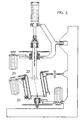
- figure 1 there is a cross section figure of the gyratory compaction device according to one method according to the invention from side, and in figure 2 there is a cross section figure of the gyratory compaction device according to another method according to the invention.
- figure 1 there is the frame 1, the specimen cylinder 2, the upper platen of the specimen cylinder 3, the lower platen of the specimen cylinder 4, the control construction of the specimen cylinder 5, the regulating device of the angle of inclination of the specimen cylinder 6, rotating device of the specimen cylinder 7, the shaft of the upper platen 8, the rotating device of the shaft of the upper platen 9, bearings of the shaft of the upper platen 10, the moving attachment of the shaft of the upper platen and its drive mechanism 11, the pneumatic cylinder functioning as a pressing device 12, the moving end of the pneumatic cylinder 13, the connecting organ of the pneumatic cylinder 14, the fixing shoulder of the pneumatic cylinder 15, bearings of the lower platen 16 and the rotating device of the lower platen 17 in the gyratory compaction device. Furthermore there are drive mechanisms 18, 19 and 20 to rotate the upper platen, the specimen cylinder and the lower platen and also other earlier known connecting parts and mechanical components to connect various parts of the gyratory compaction device with one another in due form.
- the frame 1 of the gyratory compaction device according to figure 1 has been made of steel plates and using various existing mechanical and connecting components like groove ball bearings and bolts. Plate parts like various fixing constructions and housing have been made by bending and cutting the plate and by using various connecting methods.
- the construction of the frame is earlier known so that the outer shape of the frame resembles frames of earlier known gyratory compaction devices.
- the specimen cylinder 2 has been connected to the rotating inner cylinder mounted in bearings to the control construction 5 in a removable way.
- the control construction has been fixed in a lower part of the solid part turnable to the frame 1.
- the specimen cylinder 2 is a cylindric object made of a steel pipe slightly broaden in a suitable way from the upper and lower ends.
- the specimen cylinder locks by means of its broadened parts to the shoulders of the upper and lower ends of the inner cylinder of the control construction, when the specimen cylinder is placed inside the control construction.
- the rotating device in the upper part of the specimen cylinder consists of a primary wheel and a secondary wheel and a chain or a belt adjusted between them.
- the smaller primary wheel of the rotating device has been adjusted to the end of the shaft of the drive mechanism 19 fixed to the control construction.
- the purpose of the rotating device of the specimen cylinder is to rotate the specimen cylinder as required.
- the upper platen 3 of the specimen cylinder 2 is a flange made of the shaft 8. It has been connected to the shaft in the way that the upper platen can be rotated inside the specimen cylinder by rotating the shaft.
- the diameter of the upper platen is the same as the inner diameter of the specimen cylinder, however adjustable inside the cylinder.
- the shaft 8 has been connected by means of bearings 10 so that it can be rotated and moved vertically to the construction 11 fixed to the frame 1 so that it can be moved sideways. Because of it the shaft and the upper platen adjusted inside the specimen cylinder move sideways with the upper part of the specimen cylinder.
- To rotate the shaft 8 it has been connected with a secondary wheel of the rotating device 9 adjusted to the shaft in rotating direction but moving in axial direction.
- a joint element 14 has been connected with bearings to the upper end of the shaft. This element allows rotation of the shaft, but transmits the motions of the moving end 13 of the pneumatic cylinder that has been adjusted to the shoulder 15 of the attachment 11 moving sideways to the shaft and the upper platen.
- the shaft 8 and the upper platen 3 can be moved with the pneumatic cylinder 12 functioning as a pressing device vertically inside the specimen cylinder in functional way. Because of the attachment moving sideways the pressing device can be moved as wanted according to the angle of the specimen cylinder.
- Lineary moving operating device 12 which moves vertically the upper platen 3 and the shaft 8 functioning as a pressing device is in the application according to figure 1 a double-acting pneumatic cylinder. By means of its moving end 13 the upper platen can be moved up and down and press it against the specimen. The pressing force is maintained constant according to the densifying test by regulating the pressure of the pneumatic cylinder.
- bearings 10 There are grooves for the bearings on the shaft 8 of the upper platen 3, where the axial shoulders (not presented in figures 1 and 2 ) of the corresponding shape are locked preventing the sliding of the rotating side of the bearing and of the secondary wheel of the rotating device on the axle in rotating direction.
- Mounting in bearings 10 has been accomplished in other parts in earlier known methods according to figure 1 with two radial bearings attached to the construction 11 movable sideways and vertically at a certain distant from one another.
- Construction 11 movable sideways consists of a part, fixed movable sideways to the frame and including shoulders for bearings 10 of the shaft 8 and for pneumatic cylinder 12.
- the construction movable sideways has been connected with drive mechanism 19 of the shaft 8. In the end of the shaft of the drive mechanism there is the primary wheel of the rotating device 9.
- a connecting element 14 has been mounted in bearings to connect the shaft with the pneumatic cylinder 12 functioning as a pressing device.
- the connecting element 14 is a component designed to the shape of the end of the shaft 8 and to which the earlier mentioned bearings are adjusted.
- the lower platen 4 has been adjusted to the frame 1 with a vertical shaft and bearings 16 in the way that the lower platen is placed in the lower part of the specimen cylinder according to the figure 1 and 2 inside the specimen cylinder.
- the lower platen is by size and shape a flange like element equivalent to the upper platen and it has been made of the same steel element as the shaft of the lower platen.
- the other end of the shaft of the lower platen reaches the lower part of the bearings.
- the primary wheel of the rotating device has been adjusted to the end of the shaft of the drive mechanism 20 of the rotating device of the lower platen.
- the rotating device and the drive mechanism connected to the lower platen it can be rotated with the specimen cylinder and the upper platen. Because of the construction described above the specimen cylinder, the upper platen and the lower platen form a unit, inside of which a specimen of mass of desired size and according to the dimensions of the specimen cylinder can be placed.
- the regulating device 6 of the angle of inclination of the specimen cylinder in the application according to figure 1 is a bolt organ which is rotated by fingers and the length of which changes according to the direction of rotation of the bolt organ.
- the regulating device is self locking thus the length and the angle of inclination of the control construction 5 of the specimen cylinder stays in adjusted position without other locking elements.
- the regulating device has been adjusted to the frame by a turnable fixing element in the fixed end. The fixing of the moving end to the control construction of the specimen cylinder is turnable so that the inclining mechanism of the control construction of the specimen cylinder and the regulating device would function as needed.
- Drive mechanisms of the specimen cylinder, the upper platen and the lower platen are in the application according to figure 1 alternating current motors. Transmission from the primary wheels on the shafts of the drive mechanisms to the secondary wheels has been accomplished by chain or belt transmission. Speed of rotation and the gear ratio i.e. the relationship between the size of the primary and secondary wheels of all drive mechanisms is the same so that the speed of rotation of the specimen cylinder, the upper platen and the lower platen would be as equivalent as possible.
- the frame, the specimen cylinder and the upper platen are equivalent to those in the application in figure 1 .
- the rotating device, drive mechanism and the fixing elements of the specimen cylinder, the upper platen and the lower platen as well as the regulating device between the upper part of the control construction and the frame are equivalent to those presented in the application according to figure 1 .
- the strut of the specimen cylinder is, however, different. It is organised by means of rolls 21 supporting the inner cylinder of the control construction and mounted in bearings in every 120 degrees seen from above around the specimen cylinder.
- the rolls supporting the inner cylinder are adjusted according to figure 2 to the outer cylindrical construction of the control construction 22 in the place of the upper and lower part of the specimen cylinder.
- the inner cylinder of the control construction between them and the removable specimen cylinder adjusted to it are to be rotated with respect to their central axle according to the invention.
- Preparing stages for a specimen of mass in starting the compaction test with a gyratory compaction device according to figures 1 and 2 are accomplished according to earlier known methods.
- the actual compaction of the specimen is realized by compressing the specimen by a pneumatic cylinder 12 and rotating the cylinder, the upper platen and the lower platen while the specimen stays inside the specimen cylinder.
- the specimen cylinder and the specimen itself are rotated according to the method according to the invention about its own central axle for instance for a pre-set number of gyrations or until target change in density has been achieved.
- the compaction pressure stays constant during the rotation. Compaction pressure and the other parameters can be chosen according to the regulations in standards for the material of the specimen.
- the rotation of the mass specimen with the inclined cylinder and the horizontal upper platen and the lower platen provides at different points according to radius a vertical sine-shaped reversal cross sectional deformation. This provides densifying accordingly to the earlier known gyratory compaction devices.
- the number of cycles of the specimen cylinder corresponds to the number of cycles like gyratory motions of the earlier known devices. Therefore by means of the gyratory compaction device according to the invention the compaction behaviour of bituminous and concrete mass samples can be determined as could be done with known gyratory compaction devices.
- the frame 1 can be accomplished in very many various ways. As distinct from the application in figures 1 and 2 it can be realized of various kinds of mould elements or metallic parts using various kinds of connecting and/or fixing elements. Also the shape and dimensions of the frame may vary for instance depending on the construction of various devices and mechanical elements.
- the specimen cylinder 2 of the gyratory compaction device according to the invention can be realized by many other ways and also of other material than steel. It may be made of aluminium or plastic in some other application.
- the dimensions, shapes and fixing methods of the specimen cylinder to the frame may differ from the applications according to figures 1 and 2 .
- the specimen cylinder can be supported at the lower part with a lower platen only inside the cylinder in the third application modified from the application according to figure 2 . In this case the fixing of the lower part of the specimen cylinder does not need other separate fixing elements, but the turnable fixing to the lower platen can be accomplished for instance with a lower platen adjusted turnable without clearance and sliding inside the specimen cylinder.
- the upper platen 3 and the construction of the rotating device 7 connected to it can also vary.
- the upper platen may be a separate part, adjusted vertically movable with respect to the shaft 8. This part is moved by means of a pivot going through the shaft in vertical direction and rotates with the shaft and has been mounted in axial bearings to the moving end 13 of the pneumatic cylinder.
- the size of the specimen cylinder can be chosen according to standards, therefore the method and the device can be applied for materials of various particle sizes.
- Control of temperature and the pressing force of the upper platen and the lower platen can be chosen to meet various requirements.
- All necessary equipment for control, regulation and measurements can be adjusted to the device according to the invention, in order to realize necessary measurement according to various requirements and standards.
- the method and the device according to the invention can be applied to many other researches and product development projects where it is not necessary to use amounts of specimen and/or specimen cylinders according to standards of today.
Landscapes
- Immunology (AREA)
- Pathology (AREA)
- Life Sciences & Earth Sciences (AREA)
- Chemical & Material Sciences (AREA)
- Analytical Chemistry (AREA)
- Biochemistry (AREA)
- Health & Medical Sciences (AREA)
- General Health & Medical Sciences (AREA)
- Physics & Mathematics (AREA)
- General Physics & Mathematics (AREA)
- Road Paving Machines (AREA)
- Sampling And Sample Adjustment (AREA)
- Investigating Strength Of Materials By Application Of Mechanical Stress (AREA)
- Investigation Of Foundation Soil And Reinforcement Of Foundation Soil By Compacting Or Drainage (AREA)
- Sorting Of Articles (AREA)
- Length Measuring Devices With Unspecified Measuring Means (AREA)
Claims (9)
- Verfahren zum Messen der Verdichtungseigenschaften von Bodenmassen und anderen Massen dieser Art, wobei ein Rahmen (1) mit einer Tragekonstruktion (5), eine Pressvorrichtung (12, 13), ein Probenzylinder (2) mit einer Mittelachse, eine obere Platte (3) und eine untere Platte (4) benutzt wird, wobei das Verfahren die folgenden Schritte umfasst:- Anordnen einer Massenprobe in dem Zylinder (2);- Drehen des Zylinders (2) und der Massenprobe um die Mittelachse des Zylinders;- Pressen der Massenprobe zwischen einer oberen Platte (3) und einer unteren Platte (4) unter Anwendung eines Standarddrucks;- und Messen der Höhe der Massenprobe als Indikator für die Verdichtungseigenschaft der Massenprobe, gekennzeichnet durch das- Drehen des Zylinders und der Massenprobe um die Zylindermittelachse um seine schräge Mittelachse, die in Bezug auf die obere Platte (3) und eine untere Platte (4) geneigt ist und so für die Verformungen sorgt, welche die Probe verdichten, und das- Beibehalten des Neigungswinkels der Probe durch die Tragekonstruktion (5) während der Verdichtung.
- Vorrichtung zum Messen der Verdichtungseigenschaften von Bodenmassen und anderen Massen dieser Art, welche einen Rahmen (1) mit einer Tragekonstruktion (5), einen Probenzylinder (2), eine Pressvorrichtung (12, 13) und eine obere Platte (3) und eine untere Platte (4) umfasst, die mit einer Pressvorrichtung gegen eine Probe gepresst werden, und wobei die Platten in Bezug auf die Mittelachse eines Probenzylinders geneigt sind, wobei der Probenzylinder (2) so an dem Rahmen (1) angebracht ist, dass er hauptsächlich um seine Mittelachse gedreht wird, die im Verhältnis zur Vertikalachse angewinkelt ist, dadurch gekennzeichnet, dass der Probenzylinder (2) in Lagerungen an der Tragekonstruktion (5) angebracht ist, deren unterer Teil beweglich an dem Rahmen (1) angebracht ist, und dass der Neigungswinkel der Probe während der Verdichtung aufgrund der Tragekonstruktion (5) dieselbe Position aufweist.
- Vorrichtung nach Anspruch 2, dadurch gekennzeichnet, dass zwischen dem oberen Teil der Tragekonstruktion (5) und dem Rahmen (1) eine Regulierungsvorrichtung (6) angeordnet ist, um die Tragekonstruktion und den Probenzylinder (2) in die gewünschte Position zu neigen.
- Vorrichtung nach einem der Ansprüche 2 bis 3, dadurch gekennzeichnet, dass sie eine Drehvorrichtung (7) umfasst, die mit einem Probenzylinder (2) verbunden ist, um den Probenzylinder und die Probe während der Verdichtung zu drehen.
- Vorrichtung nach einem der Ansprüche 2 bis 4, dadurch gekennzeichnet, dass sie eine Drehvorrichtung (9, 18) umfasst, die mit der oberen Platte (3) verbunden ist, um die obere Platte und die Probe während der Verdichtung zu drehen.
- Vorrichtung nach einem der Ansprüche 2 bis 5, dadurch gekennzeichnet, dass sie eine Drehvorrichtung (12, 20) umfasst, die mit der unteren Platte (4) verbunden ist, um die untere Platte und die Probe während der Verdichtung zu drehen.
- Vorrichtung nach einem der Ansprüche 2 bis 6, dadurch gekennzeichnet, dass der Probenzylinder (2) an seinem oberen Teil mittels mindestens zweier Rollen, die in der Lagerung an dem Rahmen angebracht sind, von dem Rahmen (1) getragen wird.
- Vorrichtung nach Anspruch 7, dadurch gekennzeichnet, dass sie Rollen umfasst, die in Lagerungen an dem Rahmen (1) angebracht sind und mittels einer Regulierungsvorrichtung zu bewegen sind, um den Probenzylinder in die gewünschte Position zu neigen.
- Vorrichtung nach einem der Ansprüche 2 bis 8, dadurch gekennzeichnet, dass der untere Teil des Probenzylinders (2) nur von der unteren Platte (4) getragen wird, um den unteren Teil des Probenzylinders in Lagerungen an dem Rahmen (1) anzubringen.
Applications Claiming Priority (3)
| Application Number | Priority Date | Filing Date | Title |
|---|---|---|---|
| FI20001129A FI114171B (fi) | 2000-05-12 | 2000-05-12 | Menetelmä ja laite maamassojen ja muiden niiden kaltaisten massojen tiivistysominaisuuksien mittaamiseksi |
| FI20001129 | 2000-05-12 | ||
| PCT/FI2001/000446 WO2001086251A1 (en) | 2000-05-12 | 2001-05-10 | Method and apparatus for measuring packing properties of soil masses and other similar masses |
Publications (2)
| Publication Number | Publication Date |
|---|---|
| EP1292817A1 EP1292817A1 (de) | 2003-03-19 |
| EP1292817B1 true EP1292817B1 (de) | 2009-09-02 |
Family
ID=8558373
Family Applications (1)
| Application Number | Title | Priority Date | Filing Date |
|---|---|---|---|
| EP01934030A Expired - Lifetime EP1292817B1 (de) | 2000-05-12 | 2001-05-10 | Verfahren und vorrichtung zur messung von packungseigenschaften von erdmassen und anderen ähnlichen massen |
Country Status (8)
| Country | Link |
|---|---|
| US (1) | US6729189B2 (de) |
| EP (1) | EP1292817B1 (de) |
| AT (1) | ATE441845T1 (de) |
| AU (2) | AU2001260347B2 (de) |
| CA (1) | CA2408365A1 (de) |
| DE (1) | DE60139775D1 (de) |
| FI (1) | FI114171B (de) |
| WO (1) | WO2001086251A1 (de) |
Cited By (1)
| Publication number | Priority date | Publication date | Assignee | Title |
|---|---|---|---|---|
| CN105910846A (zh) * | 2016-06-24 | 2016-08-31 | 镇江市建科工程质量检测中心有限公司 | 一种用于环刀法测试土密度的取土机 |
Families Citing this family (77)
| Publication number | Priority date | Publication date | Assignee | Title |
|---|---|---|---|---|
| GB2378766A (en) * | 2001-08-14 | 2003-02-19 | Ele Internat Ltd | Apparatus for testing compaction of material samples |
| FI119035B (fi) | 2002-03-22 | 2008-06-30 | Antti Paakkinen | Menetelmä ja laitteisto kiertotiivistimen joustojen määrittämiseksi |
| US6925889B2 (en) * | 2002-10-18 | 2005-08-09 | Pine Instrument Company | Devices and methods for applying known resistance loads and measuring internal angles of gyration in gyratory compactors |
| US7121149B2 (en) * | 2003-01-10 | 2006-10-17 | Troxler Electronic Laboratories, Inc. | Gyratory compactor apparatus and associated devices and methods |
| US7107858B2 (en) * | 2003-06-30 | 2006-09-19 | Test Quip Llc | Hot mix asphalt load simulator |
| US7584671B2 (en) * | 2005-06-21 | 2009-09-08 | Architecture And Building Research Institute, Ministry Of The Interior | Apparatus for testing the load bearing strength of an architectural structure |
| US7624646B2 (en) * | 2007-02-27 | 2009-12-01 | Corning Incorporated | Systems and methods for evaluating material for pulling rolls |
| US8359900B2 (en) * | 2009-01-09 | 2013-01-29 | Troxler Electronic Laboratories, Inc. | Calibration of gyratory compactor apparatuses and associated methods |
| US8438914B2 (en) * | 2010-11-13 | 2013-05-14 | Gregory P. Martiska | Apparatus for measuring the unconfined yield strength and time unconfined yield strength of bulk granular material |
| US9671385B2 (en) * | 2014-05-15 | 2017-06-06 | H. Joseph Buhac | Compaction testing sampler assembly |
| CN106353161A (zh) * | 2016-11-14 | 2017-01-25 | 北京市地质工程勘察院 | 一种搓条仪 |
| CN107907661A (zh) * | 2017-12-15 | 2018-04-13 | 中国科学院地质与地球物理研究所兰州油气资源研究中心 | 盆地深部储层岩石与流体相互作用模拟装置及使用方法 |
| CN108037016B (zh) * | 2017-12-28 | 2020-08-18 | 太原理工大学 | 超临界co2反应釜及岩体蠕变扩散侵蚀试验系统 |
| CN108414273A (zh) * | 2018-05-02 | 2018-08-17 | 西北综合勘察设计研究院 | 一种用于检测砂石垫层密实度的挖掘装置及其方法 |
| US11589509B2 (en) | 2018-10-26 | 2023-02-28 | Deere & Company | Predictive machine characteristic map generation and control system |
| US11079725B2 (en) | 2019-04-10 | 2021-08-03 | Deere & Company | Machine control using real-time model |
| US11467605B2 (en) | 2019-04-10 | 2022-10-11 | Deere & Company | Zonal machine control |
| US11957072B2 (en) | 2020-02-06 | 2024-04-16 | Deere & Company | Pre-emergence weed detection and mitigation system |
| US11240961B2 (en) | 2018-10-26 | 2022-02-08 | Deere & Company | Controlling a harvesting machine based on a geo-spatial representation indicating where the harvesting machine is likely to reach capacity |
| US11641800B2 (en) | 2020-02-06 | 2023-05-09 | Deere & Company | Agricultural harvesting machine with pre-emergence weed detection and mitigation system |
| US12069978B2 (en) | 2018-10-26 | 2024-08-27 | Deere & Company | Predictive environmental characteristic map generation and control system |
| US11672203B2 (en) | 2018-10-26 | 2023-06-13 | Deere & Company | Predictive map generation and control |
| US11653588B2 (en) | 2018-10-26 | 2023-05-23 | Deere & Company | Yield map generation and control system |
| US11178818B2 (en) | 2018-10-26 | 2021-11-23 | Deere & Company | Harvesting machine control system with fill level processing based on yield data |
| US11234366B2 (en) | 2019-04-10 | 2022-02-01 | Deere & Company | Image selection for machine control |
| US11778945B2 (en) | 2019-04-10 | 2023-10-10 | Deere & Company | Machine control using real-time model |
| CN110320149B (zh) * | 2019-08-02 | 2021-08-03 | 西南石油大学 | 一种流向可调式不规则岩样高压渗透装置及测试方法 |
| US12329148B2 (en) | 2020-02-06 | 2025-06-17 | Deere & Company | Predictive weed map and material application machine control |
| US12225846B2 (en) | 2020-02-06 | 2025-02-18 | Deere & Company | Machine control using a predictive map |
| US12035648B2 (en) | 2020-02-06 | 2024-07-16 | Deere & Company | Predictive weed map generation and control system |
| US11477940B2 (en) | 2020-03-26 | 2022-10-25 | Deere & Company | Mobile work machine control based on zone parameter modification |
| US11635765B2 (en) | 2020-10-09 | 2023-04-25 | Deere & Company | Crop state map generation and control system |
| US12550802B2 (en) | 2020-10-08 | 2026-02-17 | Deere & Company | Predictive machine characteristic map generation and control system |
| US11845449B2 (en) | 2020-10-09 | 2023-12-19 | Deere & Company | Map generation and control system |
| US12419220B2 (en) | 2020-10-09 | 2025-09-23 | Deere & Company | Predictive map generation and control system |
| US12013245B2 (en) | 2020-10-09 | 2024-06-18 | Deere & Company | Predictive map generation and control system |
| US12069986B2 (en) | 2020-10-09 | 2024-08-27 | Deere & Company | Map generation and control system |
| US11711995B2 (en) | 2020-10-09 | 2023-08-01 | Deere & Company | Machine control using a predictive map |
| US11927459B2 (en) | 2020-10-09 | 2024-03-12 | Deere & Company | Machine control using a predictive map |
| US11874669B2 (en) | 2020-10-09 | 2024-01-16 | Deere & Company | Map generation and control system |
| US12422847B2 (en) | 2020-10-09 | 2025-09-23 | Deere & Company | Predictive agricultural model and map generation |
| US11844311B2 (en) | 2020-10-09 | 2023-12-19 | Deere & Company | Machine control using a predictive map |
| US11474523B2 (en) | 2020-10-09 | 2022-10-18 | Deere & Company | Machine control using a predictive speed map |
| US11889788B2 (en) | 2020-10-09 | 2024-02-06 | Deere & Company | Predictive biomass map generation and control |
| US11983009B2 (en) | 2020-10-09 | 2024-05-14 | Deere & Company | Map generation and control system |
| US11864483B2 (en) | 2020-10-09 | 2024-01-09 | Deere & Company | Predictive map generation and control system |
| US11825768B2 (en) | 2020-10-09 | 2023-11-28 | Deere & Company | Machine control using a predictive map |
| US11650587B2 (en) | 2020-10-09 | 2023-05-16 | Deere & Company | Predictive power map generation and control system |
| US11895948B2 (en) | 2020-10-09 | 2024-02-13 | Deere & Company | Predictive map generation and control based on soil properties |
| US11946747B2 (en) | 2020-10-09 | 2024-04-02 | Deere & Company | Crop constituent map generation and control system |
| US11592822B2 (en) | 2020-10-09 | 2023-02-28 | Deere & Company | Machine control using a predictive map |
| US11871697B2 (en) | 2020-10-09 | 2024-01-16 | Deere & Company | Crop moisture map generation and control system |
| US11849672B2 (en) | 2020-10-09 | 2023-12-26 | Deere & Company | Machine control using a predictive map |
| US11675354B2 (en) | 2020-10-09 | 2023-06-13 | Deere & Company | Machine control using a predictive map |
| US12386354B2 (en) | 2020-10-09 | 2025-08-12 | Deere & Company | Predictive power map generation and control system |
| US20220110238A1 (en) | 2020-10-09 | 2022-04-14 | Deere & Company | Machine control using a predictive map |
| US12178158B2 (en) | 2020-10-09 | 2024-12-31 | Deere & Company | Predictive map generation and control system for an agricultural work machine |
| US11849671B2 (en) | 2020-10-09 | 2023-12-26 | Deere & Company | Crop state map generation and control system |
| US11727680B2 (en) | 2020-10-09 | 2023-08-15 | Deere & Company | Predictive map generation based on seeding characteristics and control |
| US12250905B2 (en) | 2020-10-09 | 2025-03-18 | Deere & Company | Machine control using a predictive map |
| US11889787B2 (en) | 2020-10-09 | 2024-02-06 | Deere & Company | Predictive speed map generation and control system |
| CN112748023B (zh) * | 2020-12-29 | 2023-10-31 | 广西科技大学 | 一种土工合成材料温度控制斜剪试验装置及试验方法 |
| US12127500B2 (en) | 2021-01-27 | 2024-10-29 | Deere & Company | Machine control using a map with regime zones |
| CN112964601B (zh) * | 2021-02-06 | 2022-09-09 | 青岛建一混凝土有限公司 | 砼贯入阻力仪 |
| US12229886B2 (en) | 2021-10-01 | 2025-02-18 | Deere & Company | Historical crop state model, predictive crop state map generation and control system |
| US12310286B2 (en) | 2021-12-14 | 2025-05-27 | Deere & Company | Crop constituent sensing |
| US12302791B2 (en) | 2021-12-20 | 2025-05-20 | Deere & Company | Crop constituents, predictive mapping, and agricultural harvester control |
| US12245549B2 (en) | 2022-01-11 | 2025-03-11 | Deere & Company | Predictive response map generation and control system |
| US12520759B2 (en) | 2022-01-26 | 2026-01-13 | Deere & Company | Systems and methods for predicting material dynamics |
| US12082531B2 (en) | 2022-01-26 | 2024-09-10 | Deere & Company | Systems and methods for predicting material dynamics |
| US12295288B2 (en) | 2022-04-05 | 2025-05-13 | Deere &Company | Predictive machine setting map generation and control system |
| US12298767B2 (en) | 2022-04-08 | 2025-05-13 | Deere & Company | Predictive material consumption map and control |
| US12058951B2 (en) | 2022-04-08 | 2024-08-13 | Deere & Company | Predictive nutrient map and control |
| US12358493B2 (en) | 2022-04-08 | 2025-07-15 | Deere & Company | Systems and methods for predictive power requirements and control |
| US12284934B2 (en) | 2022-04-08 | 2025-04-29 | Deere & Company | Systems and methods for predictive tractive characteristics and control |
| US12582035B2 (en) | 2022-04-08 | 2026-03-24 | Deere & Company | Systems and methods for predictive power requirements and control |
| CN117288565B (zh) * | 2023-10-11 | 2024-06-11 | 广州番禺职业技术学院 | 一种有限土体土压力测量装置及测量方法 |
Family Cites Families (25)
| Publication number | Priority date | Publication date | Assignee | Title |
|---|---|---|---|---|
| US569789A (en) * | 1896-10-20 | leland | ||
| US2972249A (en) * | 1958-02-20 | 1961-02-21 | John L Mcrae | Kneader compactor |
| FR1462343A (fr) * | 1965-10-21 | 1966-04-15 | Ethylene Plastique Sa | Procédé de mise en évidence simultanée et de mesure des propriétés mécaniquesd'un milieu viscoélastique, et balance-rhéomètre pour sa mise en oeuvre |
| US3461717A (en) * | 1968-03-29 | 1969-08-19 | Wayne A Dunlap | Gyratory compactor |
| US3478572A (en) * | 1968-07-12 | 1969-11-18 | John L Mcrae | Wall friction device |
| CH529587A (de) * | 1970-10-22 | 1972-10-31 | Von Roll Ag | Vorrichtung zur Herstellung von Blöcken |
| US3925000A (en) * | 1973-09-29 | 1975-12-09 | Wilhelm Haberle | Molding apparatus including conically-shaped compacting member |
| US3986566A (en) * | 1975-05-21 | 1976-10-19 | Rainhart Co. | Compaction apparatus |
| US3998090A (en) * | 1975-11-07 | 1976-12-21 | The United States Of America As Represented By The Secretary Of The Army | Soil compactor |
| FI71619C (fi) * | 1985-04-03 | 1987-01-19 | Partek Ab | Foerfarande och apparat foer maetning av egenskaperna speciellt foertaetningsbarheten av en troeg, gjutbar massa. |
| FI75672C (fi) * | 1986-10-02 | 1988-07-11 | Ilmari Paakkinen | Foerfarande foer maetning av egenskaper hos formbara material, saerskilt plastiska och reologiska egenskaper. |
| US4784206A (en) * | 1987-12-03 | 1988-11-15 | Combustion Engineering, Inc. | Sand vibration and compaction apparatus and method |
| US4942768A (en) * | 1989-06-06 | 1990-07-24 | Mcrae John L | Paving material testing machine |
| US5036709A (en) * | 1989-06-06 | 1991-08-06 | Mcrae John L | Paving materials testing machine |
| US5275056A (en) * | 1992-10-20 | 1994-01-04 | Rainhart Co. | Gyratory shear material compacting device |
| US5323655A (en) * | 1993-04-23 | 1994-06-28 | Troxler Electronic Laboratories, Inc. | Method and apparatus for compacting material samples |
| FI96243C (fi) | 1993-10-26 | 1996-05-27 | Ilmari Paakkinen | Menetelmä ja laite rakeisten maamassojen ominaisuuksien mittaamiseksi |
| US5456118A (en) * | 1994-02-18 | 1995-10-10 | Pine Instrument Company | Gyratory compactor |
| US5606133A (en) * | 1995-10-06 | 1997-02-25 | Pine Instrument Company | Gyratory compactor with mold specimen extruder |
| US5817946A (en) * | 1996-10-28 | 1998-10-06 | Test Quip, Inc. | Gyratory compaction apparatus for creating compression and shear forces in a sample material |
| US5824913A (en) * | 1997-01-10 | 1998-10-20 | Pine Instrument Company | Portable gyratory compactor and extruder with a single pivot and two gyration actuators |
| US5916504A (en) * | 1997-07-07 | 1999-06-29 | Pavement Technology, Inc. | Method for forming a test specimen from a mixture of asphalt concrete |
| US5911164A (en) * | 1998-02-10 | 1999-06-08 | Mcrae; John L. | Compaction and pavement design testing machine and method for testing flexible pavement materials |
| US5939642A (en) * | 1998-03-25 | 1999-08-17 | Troxler Electronic Laboratories, Inc. | Gyratory compactor |
| FR2781283B1 (fr) * | 1998-07-15 | 2000-10-06 | France Etat Ponts Chaussees | Presse a cisaillement giratoire |
-
2000
- 2000-05-12 FI FI20001129A patent/FI114171B/fi not_active IP Right Cessation
-
2001
- 2001-05-10 WO PCT/FI2001/000446 patent/WO2001086251A1/en not_active Ceased
- 2001-05-10 AU AU2001260347A patent/AU2001260347B2/en not_active Ceased
- 2001-05-10 CA CA002408365A patent/CA2408365A1/en not_active Abandoned
- 2001-05-10 AT AT01934030T patent/ATE441845T1/de not_active IP Right Cessation
- 2001-05-10 AU AU6034701A patent/AU6034701A/xx active Pending
- 2001-05-10 EP EP01934030A patent/EP1292817B1/de not_active Expired - Lifetime
- 2001-05-10 DE DE60139775T patent/DE60139775D1/de not_active Expired - Lifetime
-
2002
- 2002-11-12 US US10/292,229 patent/US6729189B2/en not_active Expired - Lifetime
Cited By (2)
| Publication number | Priority date | Publication date | Assignee | Title |
|---|---|---|---|---|
| CN105910846A (zh) * | 2016-06-24 | 2016-08-31 | 镇江市建科工程质量检测中心有限公司 | 一种用于环刀法测试土密度的取土机 |
| CN105910846B (zh) * | 2016-06-24 | 2020-02-07 | 镇江市建设工程质量检测中心有限公司 | 一种用于环刀法测试土密度的取土机 |
Also Published As
| Publication number | Publication date |
|---|---|
| US20030089178A1 (en) | 2003-05-15 |
| DE60139775D1 (de) | 2009-10-15 |
| US6729189B2 (en) | 2004-05-04 |
| FI114171B (fi) | 2004-08-31 |
| CA2408365A1 (en) | 2001-11-15 |
| EP1292817A1 (de) | 2003-03-19 |
| ATE441845T1 (de) | 2009-09-15 |
| FI20001129L (fi) | 2001-11-13 |
| AU2001260347B2 (en) | 2006-03-02 |
| AU6034701A (en) | 2001-11-20 |
| WO2001086251A1 (en) | 2001-11-15 |
Similar Documents
| Publication | Publication Date | Title |
|---|---|---|
| EP1292817B1 (de) | Verfahren und vorrichtung zur messung von packungseigenschaften von erdmassen und anderen ähnlichen massen | |
| AU2001260347A1 (en) | Method and apparatus for measuring packing properties of soil masses and other similar masses | |
| US6026692A (en) | Gyratory compaction apparatus for creating compression and shear forces in a sample material | |
| CA2158735C (en) | Method and apparatus for compacting material samples | |
| US20110158745A1 (en) | Vibratory system for a compactor | |
| FI75672C (fi) | Foerfarande foer maetning av egenskaper hos formbara material, saerskilt plastiska och reologiska egenskaper. | |
| US5275056A (en) | Gyratory shear material compacting device | |
| US3937076A (en) | Device for testing tyres for vehicles | |
| US4108009A (en) | Variable-force vibrator | |
| EP0588844B1 (de) | Zentrifugen, und verwandte vorrichtungen und verfahren (16.12.93) | |
| AU2020273297A1 (en) | Method and Device for Measuring an Axial Displaceability of a Rotatably Mounted Shaft | |
| EP3516362A1 (de) | Schwingungserreger zur belastungsprüfung eines rotorblatts, system, prüfstand und anordnung mit einem solchen schwingungserreger sowie betriebsverfahren | |
| US2972249A (en) | Kneader compactor | |
| CH666758A5 (de) | Vorrichtung zur veraenderung der durch eine rotierende masse erzeugten vibrationskraft. | |
| US5824913A (en) | Portable gyratory compactor and extruder with a single pivot and two gyration actuators | |
| AU745872B2 (en) | Gyratory shear press | |
| US3461717A (en) | Gyratory compactor | |
| CN211426108U (zh) | 一种用于土石混填料的旋转压实装置 | |
| CN1053737C (zh) | 压实材料试样的方法和装置 | |
| FI115618B (fi) | Sovitelma ja menetelmä tiivistysliikkeen aikaansaamiseksi betonin valu koneessa | |
| US5429440A (en) | Mechanism for adjusting the position of supports for large rotating apparatus | |
| SU1490570A1 (ru) | Устройство дл определени коэффициентов внешнего и внутреннего трени сыпучих материалов | |
| Crockford et al. | Hollow cylinder specimen preparation: Cohesive materials | |
| CN120779015A (zh) | 一种基于精细分离的rap微表处路用性能检测系统 | |
| Morrison et al. | Design-development of a variable load tension—compression creep testing machine |
Legal Events
| Date | Code | Title | Description |
|---|---|---|---|
| PUAI | Public reference made under article 153(3) epc to a published international application that has entered the european phase |
Free format text: ORIGINAL CODE: 0009012 |
|
| 17P | Request for examination filed |
Effective date: 20021210 |
|
| AK | Designated contracting states |
Kind code of ref document: A1 Designated state(s): AT BE CH CY DE DK ES FI FR GB GR IE IT LI LU MC NL PT SE TR |
|
| AX | Request for extension of the european patent |
Extension state: AL LT LV MK RO SI |
|
| 17Q | First examination report despatched |
Effective date: 20080704 |
|
| GRAP | Despatch of communication of intention to grant a patent |
Free format text: ORIGINAL CODE: EPIDOSNIGR1 |
|
| GRAS | Grant fee paid |
Free format text: ORIGINAL CODE: EPIDOSNIGR3 |
|
| GRAA | (expected) grant |
Free format text: ORIGINAL CODE: 0009210 |
|
| AK | Designated contracting states |
Kind code of ref document: B1 Designated state(s): AT BE CH CY DE DK ES FI FR GB GR IE IT LI LU MC NL PT SE TR |
|
| REG | Reference to a national code |
Ref country code: CH Ref legal event code: EP |
|
| REG | Reference to a national code |
Ref country code: IE Ref legal event code: FG4D |
|
| REF | Corresponds to: |
Ref document number: 60139775 Country of ref document: DE Date of ref document: 20091015 Kind code of ref document: P |
|
| PG25 | Lapsed in a contracting state [announced via postgrant information from national office to epo] |
Ref country code: SE Free format text: LAPSE BECAUSE OF FAILURE TO SUBMIT A TRANSLATION OF THE DESCRIPTION OR TO PAY THE FEE WITHIN THE PRESCRIBED TIME-LIMIT Effective date: 20090902 Ref country code: FI Free format text: LAPSE BECAUSE OF FAILURE TO SUBMIT A TRANSLATION OF THE DESCRIPTION OR TO PAY THE FEE WITHIN THE PRESCRIBED TIME-LIMIT Effective date: 20090902 |
|
| NLV1 | Nl: lapsed or annulled due to failure to fulfill the requirements of art. 29p and 29m of the patents act | ||
| PG25 | Lapsed in a contracting state [announced via postgrant information from national office to epo] |
Ref country code: NL Free format text: LAPSE BECAUSE OF FAILURE TO SUBMIT A TRANSLATION OF THE DESCRIPTION OR TO PAY THE FEE WITHIN THE PRESCRIBED TIME-LIMIT Effective date: 20090902 |
|
| PG25 | Lapsed in a contracting state [announced via postgrant information from national office to epo] |
Ref country code: CY Free format text: LAPSE BECAUSE OF FAILURE TO SUBMIT A TRANSLATION OF THE DESCRIPTION OR TO PAY THE FEE WITHIN THE PRESCRIBED TIME-LIMIT Effective date: 20090902 |
|
| PG25 | Lapsed in a contracting state [announced via postgrant information from national office to epo] |
Ref country code: PT Free format text: LAPSE BECAUSE OF FAILURE TO SUBMIT A TRANSLATION OF THE DESCRIPTION OR TO PAY THE FEE WITHIN THE PRESCRIBED TIME-LIMIT Effective date: 20100104 Ref country code: ES Free format text: LAPSE BECAUSE OF FAILURE TO SUBMIT A TRANSLATION OF THE DESCRIPTION OR TO PAY THE FEE WITHIN THE PRESCRIBED TIME-LIMIT Effective date: 20091213 |
|
| PG25 | Lapsed in a contracting state [announced via postgrant information from national office to epo] |
Ref country code: AT Free format text: LAPSE BECAUSE OF FAILURE TO SUBMIT A TRANSLATION OF THE DESCRIPTION OR TO PAY THE FEE WITHIN THE PRESCRIBED TIME-LIMIT Effective date: 20090902 Ref country code: BE Free format text: LAPSE BECAUSE OF FAILURE TO SUBMIT A TRANSLATION OF THE DESCRIPTION OR TO PAY THE FEE WITHIN THE PRESCRIBED TIME-LIMIT Effective date: 20090902 |
|
| PLBE | No opposition filed within time limit |
Free format text: ORIGINAL CODE: 0009261 |
|
| STAA | Information on the status of an ep patent application or granted ep patent |
Free format text: STATUS: NO OPPOSITION FILED WITHIN TIME LIMIT |
|
| PG25 | Lapsed in a contracting state [announced via postgrant information from national office to epo] |
Ref country code: DK Free format text: LAPSE BECAUSE OF FAILURE TO SUBMIT A TRANSLATION OF THE DESCRIPTION OR TO PAY THE FEE WITHIN THE PRESCRIBED TIME-LIMIT Effective date: 20090902 |
|
| PGFP | Annual fee paid to national office [announced via postgrant information from national office to epo] |
Ref country code: FR Payment date: 20100506 Year of fee payment: 10 |
|
| 26N | No opposition filed |
Effective date: 20100603 |
|
| PG25 | Lapsed in a contracting state [announced via postgrant information from national office to epo] |
Ref country code: GR Free format text: LAPSE BECAUSE OF FAILURE TO SUBMIT A TRANSLATION OF THE DESCRIPTION OR TO PAY THE FEE WITHIN THE PRESCRIBED TIME-LIMIT Effective date: 20091203 |
|
| PGFP | Annual fee paid to national office [announced via postgrant information from national office to epo] |
Ref country code: GB Payment date: 20100519 Year of fee payment: 10 |
|
| PG25 | Lapsed in a contracting state [announced via postgrant information from national office to epo] |
Ref country code: MC Free format text: LAPSE BECAUSE OF NON-PAYMENT OF DUE FEES Effective date: 20100531 |
|
| REG | Reference to a national code |
Ref country code: CH Ref legal event code: PL |
|
| PG25 | Lapsed in a contracting state [announced via postgrant information from national office to epo] |
Ref country code: LI Free format text: LAPSE BECAUSE OF NON-PAYMENT OF DUE FEES Effective date: 20100531 Ref country code: CH Free format text: LAPSE BECAUSE OF NON-PAYMENT OF DUE FEES Effective date: 20100531 |
|
| PG25 | Lapsed in a contracting state [announced via postgrant information from national office to epo] |
Ref country code: IE Free format text: LAPSE BECAUSE OF NON-PAYMENT OF DUE FEES Effective date: 20100510 |
|
| GBPC | Gb: european patent ceased through non-payment of renewal fee |
Effective date: 20110510 |
|
| REG | Reference to a national code |
Ref country code: FR Ref legal event code: ST Effective date: 20120131 |
|
| PG25 | Lapsed in a contracting state [announced via postgrant information from national office to epo] |
Ref country code: FR Free format text: LAPSE BECAUSE OF NON-PAYMENT OF DUE FEES Effective date: 20110531 |
|
| PG25 | Lapsed in a contracting state [announced via postgrant information from national office to epo] |
Ref country code: GB Free format text: LAPSE BECAUSE OF NON-PAYMENT OF DUE FEES Effective date: 20110510 |
|
| PG25 | Lapsed in a contracting state [announced via postgrant information from national office to epo] |
Ref country code: LU Free format text: LAPSE BECAUSE OF NON-PAYMENT OF DUE FEES Effective date: 20100510 |
|
| PG25 | Lapsed in a contracting state [announced via postgrant information from national office to epo] |
Ref country code: TR Free format text: LAPSE BECAUSE OF FAILURE TO SUBMIT A TRANSLATION OF THE DESCRIPTION OR TO PAY THE FEE WITHIN THE PRESCRIBED TIME-LIMIT Effective date: 20090902 |
|
| PGFP | Annual fee paid to national office [announced via postgrant information from national office to epo] |
Ref country code: DE Payment date: 20130522 Year of fee payment: 13 |
|
| REG | Reference to a national code |
Ref country code: DE Ref legal event code: R119 Ref document number: 60139775 Country of ref document: DE |
|
| REG | Reference to a national code |
Ref country code: DE Ref legal event code: R119 Ref document number: 60139775 Country of ref document: DE Effective date: 20141202 |
|
| PG25 | Lapsed in a contracting state [announced via postgrant information from national office to epo] |
Ref country code: DE Free format text: LAPSE BECAUSE OF NON-PAYMENT OF DUE FEES Effective date: 20141202 |
|
| PGFP | Annual fee paid to national office [announced via postgrant information from national office to epo] |
Ref country code: IT Payment date: 20200505 Year of fee payment: 20 |