Technical Field
The present invention relates to a radio reception
apparatus and radio reception method for use in a digital
wireless communication system.
Background Art
In view of the spread and development of wireless
internet connections, high-speed, large volume wireless
communication has drawn attention over recent years. In order
to implement this high-speed, large volume communication, the
W-CDMA (Wideband-Code Division Multiple Access) scheme has come
under attention, and under the conditions of multi-path fading,
coherent RAKE combining reception holds great significance.
In order to realize the above, highly accurate reception timing
detection for every path (path search) and channel estimation
are needed.
To meet these needs, iterative path search and channel
estimation are being studied. Such iterative path search and
channel estimation are disclosed in "Iterative
Decision-Directed Path Search and Channel Estimation For
Multi-Carrier/DS-CDMA Broadband Packet Wireless Access" by
Atarashi, Abeta, Sawahashi, and Adachi, in Technical Report
of IEICE, RCS2000-4 (2000-04). According to this technique,
after performing the initial path search and channel estimation
using only pilot symbols and performing RAKE combining and error
correction decoding, the decision-directed data symbols after
decoding are added to the pilot symbols and path search and
channel estimation are recursively repeated. By this means,
it is possible to improve reception performance.
However, by the above-mentioned iterative path search
and channel estimation, cases might arise where performance
improvement is little due to decoding errors from early stages
of repetition. In addition, the above technique is based on
the premise that known signals and data signals are
time-multiplexed and the transmission power is even. Because
of this, in case DPDCH (Dedicated Physical Data CHannel) and
DPCCH (Dedicated Physical Control CHannel) are
code-multiplexed and their normal transmission power rates vary
such as uplink channel signals in W-CDMA, it is not possible
to use them for accurate iterative path search and channel
estimation, and consequently, little performance improvement
can be expected.
Summary of the invention
An object of the present invention is to provide a
radio reception apparatus and radio reception method that reduce
the effect of bit errors from early stages of repetition and
that enable accurate iterative path search and channel
estimation even in case transmission power rates differ between
known signals and data signals.
Brief Description of Drawings
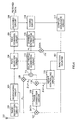
FIG.1 is a block diagram showing a configuration of
a wireless base station apparatus comprising a radio reception
apparatus according to Embodiment 1 of the present invention;
FIG.2 is a block diagram showing a configuration of
a communications terminal apparatus that performs wireless
communication with a wireless base station apparatus comprising
a radio reception apparatus of the present invention;
Fig.3A shows a state of mapping of PL signal according
to Embodiment 1 of the present invention;
Fig.3B shows a state of mapping of pseudo PL signal
according to Embodiment 1 of the present invention;
Fig.3C shows a state where pseudo PL signal is
phase-corrected through a phase correction circuit according
to Embodiment 1 of the present invention;
FIG.3D shows a state of signal in which PL signal and
pseudo PL signal according to Embodiment 1 of the present
invention are added;
FIG.3E describes delay profile generation according
to Embodiment 1 of the present invention;
FIG.4 is a block diagram showing a configuration of
a wireless base station apparatus comprising a radio reception
apparatus according to Embodiment 2 of the present invention;
FIG.5 is a block diagram showing a configuration of
a wireless base station apparatus comprising a radio reception
apparatus according to Embodiment 3 of the present invention;
FIG.6 is a block diagram showing a configuration of
a wireless base station apparatus comprising a radio reception
apparatus according to Embodiment 4 of the present invention;
FIG.7 is a block diagram showing a configuration of
a wireless base station apparatus comprising a radio reception
apparatus according to Embodiment 5 of the present invention;
FIG.8A describes delay profile generation according
to Embodiment 5 of the present invention;
FIG.8B describes delay profile generation according
to Embodiment 5 of the present invention; and
FIG.9 is a block diagram showing a configuration of
a communications terminal apparatus comprising a radio
reception apparatus according to Embodiment 6 of the present
invention.
Best Mode for Carrying out the Invention
The present inventor has discovered that when
iterative path search and channel estimation using known signals
and data are to be performed, it is effective to perform weighting
and in-phase addition in order to minimize the effect of data
decision errors and thus arrived at the present invention.
That is, the essence of the present invention is that
weight is assigned to pseudo known signals made up of known
signals and to data signals according to signal quality and
in-phase addition is performed so that even where the quality
of received signals is poor, the effect of data decision errors
can be minimized and iterative path search and channel
estimation can be performed with accuracy.
With reference to the accompanying drawings now,
embodiments of the present invention will be described below.
(Embodiment 1)
A case will be described here with reference to the
present embodiment where, in iterative path search and channel
estimation, after uplink channel signals composed of
IQ-multiplexed known signals and data are subjected to phase
correction in such a way as to synchronize the phase, the signals
are assigned weight according to transmission power rates and
then in-phase addition is performed.
FIG.1 is a block diagram showing the configuration
of a wireless base station apparatus comprising a radio
reception apparatus according to Embodiment 1 of the present
invention. The wireless base station apparatus in FIG.1 shows
the configuration of the receiver side alone; however, this
wireless base station apparatus includes configuration of the
transmitter side as well.
A uplink channel signal from a communication terminal
is received in radio reception circuit 102 by way of antenna
101. In radio reception circuit 102, the uplink channel signal
is subjected to predetermined radio reception processing (i.e.,
down-conversion and A/D conversion), and the signal after radio
reception processing is output to despreading circuit 103.
In despreading circuit 103, the signal after radio
reception processing is subjected to despreading processing
using the spreading code used by the communication terminal
and output to path selection circuit 104 while also output to
multipliers 107 and 109. That is, the despread signal is output
to path selection circuit 104 for path selection. In addition,
the despread signal of the pilot (PL) portion (known signal)
of DPCCH is output to multiplier 109 while the despread signal
of the DPDCH (data) portion is output to multiplier 107.
In multiplier 107, the despread signal of the data
portion is multiplied by a complex conjugate value of data in
which decoded data is coded once again, and the result of
multiplication is output to phase correction circuit 108 as
a pseudo pilot signal. In phase correction circuit 108, the
phase of the pseudo pilot signal is shifted by 90° and the shifted
signal is output to multiplier 110.
In multiplier 110, the shifted signal is multiplied
by gain factor βd. In actuality, maximum ratio combining takes
place using βd2. The pseudo pilot signal multiplied by gain
factor βd is output to adder 111. In multiplier 109, the despread
signal (PL signal) of the PL portion is multiplied by gain factor
βc. In actuality, maximum ratio combining takes place using
βc2. The PL signal multiplied by gain factor βc is output to
adder 111. Incidentally, gain factors βc and βd are controlled
in weight controlling circuit 112.
In adder 111, the pseudo PL signal output from
multiplier 109 and the PL signal output from multiplier 110
are added, and the added PL signal after addition (that in which
the pseudo PL signal and PL signal are added) is output to delay
profile generation circuit 113.
In delay profile generation circuit 113, a delay
profile is generated using the added PL signal. This delay
profile is output to path selection circuit 104. In path
selection circuit 104, a given number of paths (reception
timings) exceeding a given threshold level are selected. The
despread signals of these selected reception timings are output
to RAKE combining circuit 105. In RAKE combining circuit 105,
channel estimation results output from channel estimation
circuit 115 are used to RAKE-combine the selected paths, and
the signal after combination is output to decoding circuit 106.
The despread signals of the reception timings selected
in path selection circuit 104 are output also to channel
estimation circuit 115. In multiplier 114, the despread signal
of the data portion is multiplied by a complex conjugate value
of data in which decoded data is coded once again, and the result
of multiplication is output to channel estimation circuit 115
as a pseudo pilot signal. In channel estimation circuit 115,
channel estimation is performed using the pseudo PL signal and
the PL signal, and this channel estimation result is output
to RAKE combining circuit 105. In decoding circuit 106, the
signal after RAKE combining is decoded and output as received
data while also output to coding circuit 116. In coding circuit
116, the decoded data is recoded and then output to complex
conjugate circuit 117. In complex conjugate circuit 117, complex
conjugates of the recoded data are picked and output to
multiplier 107 and multiplier 114.
FIG.2 is a block diagram showing the configuration
of a communications terminal apparatus that performs wireless
communication with a wireless base station apparatus comprising
a radio reception apparatus of the present invention.
A downlink channel signal from a base station is
received in radio section 202 by way of antenna 201. In radio
section 202, the downlink channel signal is subjected to
predetermined radio reception processing (e.g.,
down-conversion and A/D conversion), and the signal after radio
reception processing is output to demodulation section 203.
Demodulation section 203 performs processings such as
despreading processing, synchronous detection, RAKE combining,
channel codec, and separation.
The demodulated data demodulated in demodulation
section 203 is obtained as received data while also output to
G parameter controlling section 204. In G parameter controlling
section 204, gain factors βd and βc corresponding to the G
parameters from the base station are obtained, and transmission
data is multiplied (weighted) by these gain factors βd and βc.
That is, transmission data of DPDCH (I ch) is output to multiplier
205 and there multiplied by gain factor βd for DPDCH. The
transmission data of DPCCH (Q ch) is output to multiplier 206
and there multiplied by gain factor βc for DPCCH. In this way,
DPDCH (I ch) and DPCCH (Q ch) are gain-adjusted.
Transmission data of DPDCH and DPCCH, each multiplied
by βd or βc, are multiplexed in multiplexing section 207 and
thereafter output to modulation section 208. In modulation
section 208, the multiplexed signal is subjected to digital
modulation processing and despreading modulation processing
and the signal after demodulation is output to radio section
202.
In radio section 202, the modulated signal is subjected
to predetermined radio transmission processing (e.g., D/A
conversion and up-conversion). The signal after this radio
transmission processing is transmitted to a base station as
a uplink channel signal by way of antenna 201.
Next, the operation of a radio reception having the
above configuration will be described.
In communications terminals, transmission data is
multiplied by gain factor. That is, transmission data of DPDCH
(Ich) is multiplied by gain factor βd for DPDCH, and transmission
data of DPCCH (Q ch) is multiplied by gain factor βc for DPCCH.
These gain factors βc and βd are determined by G parameters
contained in downlink channel signals. Therefore, uplink
channel signals are gain-adjusted by gain factors βc and βd
determined in base stations.
Then, the gain-adjusted transmission data of DPDCH
and transmission data of DPCCH are IQ-multiplexed and
transmitted to as a uplink channel signal to a base station.
In the base station, despreading processing is
performed on the uplink channel signal, and the despread signal
of the PL portion (PL portions of DPCCH) and the despread signal
of the data portion (DPDCH) are obtained. At the initial path
search and channel estimation, a delay profile is generated
in delay profile generation circuit 113 using the despread
signal of the PL portion, and based on this delay profile, a
reception timing of path is selected in path selection
circuit104 (path search).
Channel estimation is performed in channel estimation
circuit 115 using the PL signals of the selected reception
timings, and using these channel estimation results, despread
signals of data portions are RAKE-combined in the RAKE combining
circuit. The signal after combination is decoded in decoding
circuit 106 to obtain received data, and meanwhile this decoded
data is subjected to recoding in coding circuit 116 and then
output to complex conjugate circuit 117. In complex conjugate
circuit 117, complex conjugates of coded data are output to
multiplier 107 and multiplier 114 for iterative path search
and channel estimation.
In multiplier 107, the despread signal of the data
portion is multiplied by a complex conjugate of the recoded
data, whereby a pseudo PL signal is obtained. As described above,
through multiplication by complex conjugates of data, the
orthogonal modulation elements of recoded data are removed,
which makes possible the use of pseudo PL signals. Now, the
process of obtaining added PL signals where the pseudo PL signal
and PL signal are added will be described with reference to
FIGs.3A∼E.
In a uplink channel signal, the PL portion (PL portion
of DPCCH) and data portion (DPDCH) are code-multiplexed (IQ
multiplexed). That is, the PL portion (PL portion of DPCCH)
and data portion (DPDCH) are multiplexed in a state where they
are subject to despreading modulation processing using
different despreading codes. Because of this, the PL signal
is mapped on the Q axis as in FIG.3A and data (pseudo PL signal)
is mapped on the I axis as in FIG.3B.
As for the data (pseudo PL signal), the phase is shifted
by 90° in phase correction circuit 108 and the data moves onto
the Q axis as in FIG.3C. Then the PL signal is multiplied by
gain factor βc in multiplier 109, and in multiplier 110, the
data (pseudo PL signal) is multiplied by gain factor βd. These
gain factors βc and βd are controlled in weight controlling
circuit 112.
Since gain factors are determined in base stations
and informed to communication terminals as G parameters, in
weight controlling circuit 112, gain factors are controlled
based on G parameters informed to communication terminals. In
such case, in weight controlling circuit 112, gain factors are
controlled considering the energy for every 1 bit in the PL
signal and pseudo PL signal.
The PL signal and data (pseudo PL signal) multiplied
by gain factors are added in adder 111 and become an added PL
signal as shown FIG.3D. This added PL signal is output to delay
profile generation circuit 113. In delay profile generation
circuit 113, a delay profile is generated using the added PL
signal.
The delay profile is output to path selection
circuit104 where path search takes place as described above,
and the information corresponding to the selected reception
timings are output to RAKE combining circuit 105 and channel
estimation circuit 115.
Meanwhile, in multiplier 114, the despread signal of
the data portion is multiplied by complex conjugates of the
recoded data, whereby a pseudo PL signal is obtained. As
described above, by multiplying complex conjugates of data,
the orthogonal modulation elements of recoded data are removed,
which makes possible the use of pseudo PL signals.
In channel estimation circuit 115, channel estimation
is performed using the pseudo PL signal and PL signal, and this
channel estimation result is output to RAKE combining circuit
105. Processings in RAKE combining circuit 105, decoding circuit
106, coding circuit 116, and in complex conjugate circuit 117
are as described above. Then, the complex conjugate data from
complex conjugate circuit 117 is output again to multiplier
107 and multiplier 114. By thus performing iterative path search
and channel estimation, the accuracy of path search and channel
estimation is heightened to improve reception performance.
As thus described, according to the present embodiment,
IQ-multiplexed (code-multiplexed) DPCCH signals and DPDCH
signals of different transmission power rates are subject to
phase rotation correction and then to in-phase addition, whereby
the number of samples per time unit increases and delay profiles
can be averaged in a shorter time period. Furthermore by thus
subjecting DPCCH signals and DPDCH signals of different
transmission power rates to in-phase addition (maximum ratio
combining) after power adjustment, it is possible to improve
the SN ratio (Signal to Noise Ratio) after in-phase addition
and perform iterative path search with high accuracy.
Although a case was described above with the present
embodiment where data (pseudo PL signal) is subjected to phase
correction and thereafter multiplied by a gain factor, the
present invention can be configured such that data (pseudo PL
signal) is multiplied by a gain factor prior to phase correction.
(Embodiment 2)
A case will be described here with the present
embodiment where DPCCH and DPDCH are assigned weight in
accordance with the number of times iterative path search and
channel estimation are repeated.
FIG.4 is a block diagram showing the configuration
of a wireless base station apparatus comprising a radio
reception apparatus according to Embodiment 2 of the present
invention. Parts in FIG.4 identical to those in above FIG.1
are assigned the same codes as in FIG.1 and their detailed
explanations are omitted.
The wireless base station apparatus shown in FIG.4
comprises repetition counter 401 that counts the number of times
iterative path search and channel estimation take place. In
repetition counter 401, the number of output times from complex
conjugate circuit 117 is counted, and the information of the
repetition times is output to weight controlling circuit 112.
As to controlling the number of repetition times, it
is also possible to use CRC (Cyclic Redundancy Check)
information and, provided that CRC is OK, stop the repetition
and counting the number of repetition times.
In weight controlling circuit 112, based on the number
of times iterative path search channel estimation take place,
gain factors βc and βd are multiplied by a predetermined
coefficient α1 and output to multiplier 109 and multiplier 110.
That is, the PL signal is multiplied by βc×α1 in multiplier
109, and the pseudo PL signal is multiplied by βd×α2 in multiplier
110.
These α1 and α2 are set from time to time in accordance
with the number of repetition times. For example, when the number
of repetition times is small, based on the assumption that the
reliability of the pseudo PL signal is low, the weight of βd
is reduced while the weight of βc is increased. That is, in
weight controlling circuit 112, α1 is made big and α2 is set
small, and this α1 is multiplied by βc and output to multiplier
109, while α2 is multiplied by βd and output to multiplier 110.
On the other hand, when the number of repetitions is
big, based on the assumption that the reliability of the pseudo
PL signal is high, the weight of βd is made big while the weight
of βc is made small. That is, in weight controlling circuit
112, α1 is made small and α2 is set big, and this α1 is multiplied
by βc and output to multiplier 109, and α2 is multiplied by
βd and output to multiplier 110.
By thus increasing the weight of the pseudo PL signal
according to the number of repetition times, i.e., as the
reliability of the pseudo PL signal becomes higher, iterative
path search and channel estimation can be performed with high
accuracy and the reception performance is enhanced.
(Embodiment 3)
A case will be described here with the present
embodiment where DPCCH and DPDCH are assigned weight according
to reception quality. A case will be described here where SIR
(Signal to Interference Ratio) is used as reception quality;
nevertheless, it is still possible to use other parameters than
SIR as reception quality.
FIG.5 is a block diagram showing the configuration
of a wireless base station apparatus comprising a radio
reception apparatus according to Embodiment 1 of the present
invention. Parts in FIG.5 identical to those in above FIG.1
are assigned the same codes as in FIG.1 and their detailed
explanations are omitted.
The wireless base station apparatus shown in FIG.5
comprises SIR measurement circuit 501 that measures SIR, which
is reception quality. In SIR measurement circuit 501, SIR is
measured using the despread signal of the PL portion that is
output from despreading circuit 103, and the measurement result
is output to weight controlling circuit 112.
In weight controlling circuit 112, based on the SIR
measurement result, gain factors βc and βd are multiplied by
a predetermined coefficient α1 and output to multiplier 109
and to multiplier 110. That is, the PL signal is multiplied
by βc×α1 inmultiplier 109, and the pseudo PL signal is multiplied
by βd×α2 in multiplier 110.
These α1 and α2 are changed and set from time to time
in accordance with SIR measurement results. For example, when
the SIR measurement result is poor, based on the assumption
that the condition of transmission path is poor and that the
reliability of the pseudo PL signal is low, the weight of βd
is reduced while the weight of βc is increased. That is, in
weight controlling circuit 112, α1 is made big and α2 is set
small, and this α1 is multiplied by βc and output to multiplier
109, while α2 is multiplied by βd and output to multiplier 110.
On the other hand, when the SIR measurement result
is good, based on the assumption that the condition of
transmission path is good and that the reliability of the pseudo
PL signal is high, the weight of βd is increased while the weight
of βc is reduced. That is, in weight controlling circuit 112,
α1 is made small and α2 is set big, and this α1 is multiplied
by βc and output to multiplier 109, while α2 is multiplied by
βd and output to multiplier 110.
As to whether SIR is good or poor, this can be determined
by, for instance, applying threshold determination to SIR
measurement results.
By thus increasing the weight of the pseudo PL signal
according to reception quality, i.e., as the reliability of
the pseudo PL signal becomes higher, iterative path search and
channel estimation can be performed with high accuracy and the
reception performance is enhanced.
(Embodiment 4)
A case will be described here with the present
embodiment where a signal after RAKE combining is subjected
to harddecision and a pseudo PL signal is generated using complex
conjugates to perform iterative path search and channel
estimation.
FIG.6 is a block diagram showing the configuration
of a wireless base station apparatus comprising a radio
reception apparatus according to Embodiment 4 of the present
invention. Parts in FIG.6 identical to those in above FIG.1
are assigned the same codes as in FIG.1 and their detailed
explanations are omitted.
The wireless base station apparatus shown in FIG.6
comprises hard decision circuit 601 that performs hard decision
of the data that is RAKE-combined in RAKE combining circuit
105. In hard decision circuit 601, the data that is RAKE combined
in RAKE combining circuit 105 is subjected to hard decision,
and this hard decision data is output to complex conjugate
circuit 117. In complex conjugate circuit 117, complex
conjugates of the hard decision data are obtained, which are
output to multiplier 107 and to multiplier 114.
According to the present embodiment, the output from
RAKE combining circuit 105 is decoded instead of being recoded,
and the output from RAKE combining circuit 105 is subjected
to hard decision and output to complex conjugate circuit 117,
and hence it is possible to increase the speed of procedure
compared to a case where decoding and recoding are performed.
Incidentally, according to the present embodiment,
data that is subject to hard decision can be the PL portion
of DPCCH as well as data of the non-PL portion and such.
(Embodiment 5)
A case will be described here with the present
embodiment where delay profiles are averaged by DPDCH alone,
and delay profiles of DPDCH are subjected to in-phase addition
after phase rotation correction, and iterative path search and
channel estimation are performed.
FIG.7 is a block diagram showing the configuration
of a wireless base station apparatus comprising a radio
reception apparatus according to Embodiment 5 of the present
invention. Parts in FIG.7 identical to those in above FIG.1
are assigned the same codes as in FIG.1 and their detailed
explanations are omitted.
According to the wireless base station apparatus shown
in FIG.7, the despread signal obtained in despreading circuit
103 is output to path selection circuit 104 for path selection,
while the despread signal of the DPCCH (PL) portion is output
to delay profile generation circuit 701 and the despread signal
of the DPDCH (data) portion is output to multiplier 107.
In multiplier 107, the despread signal of the data
portion is multiplied by a complex conjugate value of data in
which decoded data is coded once again, and the result of
multiplication is output to delay profile generation circuit
702 as a pseudo pilot signal.
In delay profile generation circuit 701, delay
profiles are generated using only DPCCH signals and averaged,
and the averaged delay profile (the upper delay profile in
FIG.8A) is output to multiplier 109.
In delay profile generation circuit 702, delay
profiles are generated using only DPDCH signals and averaged,
and the averaged delay profile (the lower delay profile in
FIG.8A) is output to phase correction circuit 108. In phase
correction circuit 108, the phase of the delay profile of the
pseudo pilot signal is shifted by 90°and the delay profile after
the shift is output to multiplier 110.
In multiplier 110, the shifted delay profile is
multiplied by gain factor βd. The delay profile of the pseudo
pilot signal thus multiplied by gain factor βd is output to
adder 111. In multiplier 109, the delay profile of DPCCH is
multiplied by gain factor βc. The delay profile multiplied by
gain factor βc is output to adder 111. Incidentally, gain factors
βc and βd are controlled in weight controlling circuit 112.
In adder 111, the delay profile of the pseudo PL signal
output from multiplier 109 and the delay profile of DPCCH output
from multiplier 110 are added, and the added delay profile after
addition (that in which the delay profile of the pseudo PL signal
and the delay profile of the PL signal are added together
(FIG.8B)) is output to power calculator circuit 703. In power
calculator circuit 703, power (I2 + Q2) is calculated from the
added delay profile, and the calculation result (power delay
profile) is output to path selection circuit 104. In path
selection circuit 104, a given number of paths exceeding a given
threshold level are selected from the power delay profile.
According to the present embodiment, delay profiles
using DPCCH alone and delay profiles using DPDCH alone are
subject to in-phase addition, and hence it is possible to reduce
the amount of operation even though the memory volume increases
compared to a case where despread signals are subject to in-phase
addition.
(Embodiment 6)
Embodiment 1 through 5 described cases of (uplink
channel signal) reception (wireless base station reception)
where DPCCH and DPDCH were IQ-multiplexed; however, a case
described here with the present embodiment (downlink channel
signal) pertains to reception (communication terminal
reception) where DPCCH and DPDCH are time-multiplexed.
FIG.9 is a block diagram showing the configuration
of a communications terminal apparatus comprising a radio
reception apparatus according to Embodiment 6 of the present
invention. The wireless base station apparatus in FIG.9 shows
the configuration of the receiving side alone; however, this
communication terminal apparatus includes the configuration
of the transmitting side as well.
A downlink channel signal from a wireless base station
apparatus is received in radio reception circuit 902 by way
of antenna 901. In radio reception circuit 902, the downlink
channel signal is subjected to predetermined radio reception
processing (e.g., down-conversion and A/D conversion), and the
signal after radio reception processing is output to despreading
circuit 903.
In despreading circuit 903, the signal after radio
reception processing is subjected to despreading processing
using the spreading code used by the wireless base station and
output to path selection circuit 904 while also output to
multiplier 907 and multiplier 908. That is, the despread signal
is output to path selection circuit 904 for path selection.
In addition, the despread signal of the pilot (PL) portion (known
signal) of DPCCH is output to multiplier 908, while the despread
signal of the DPDCH (data) portion is output to multiplier 907.
In multiplier 907, the despread signal of the data
portion is multiplied by a complex conjugate value of data in
which decoded data is coded once again, and the result of
multiplication is output to multiplier 909 as a pseudo pilot
signal.
In multiplier 909, the pseudo PL signal is multiplied
by a weight coefficient controlled by weight controlling circuit
911, and the multiplication result is output to adder 910. In
multiplier 908, the PL signal output from despreading circuit
903 is multiplied by a weight coefficient controlled by weight
controlling circuit 911, and this multiplication result is
output to adder 910. In adder 910, the pseudo PL signal multiplied
by a weight coefficient and the PL signal multiplied by a weight
coefficient are added, and the added PL signal after addition
(that in which the pseudo PL signal and PL signal are added)
is output to delay profile generation circuit 912.
In delay profile generation circuit 912, a delay
profile is generated using the added PL signal. This delay
profile is output to path selection circuit 904. In path
selection circuit 904, a given number of paths (reception
timings) exceeding a given threshold level are selected from
the delay profiles. The despread signals of these selected
reception timings are output to RAKE combining circuit 905.
In RAKE combining circuit 905, channel estimation results output
from channel estimation circuit 914 are used to RAKE-combine
the selected paths, and the signal after combination is output
to decoding circuit 906.
The despread signals of the reception timings selected
in path selection circuit 904 are output also to channel
estimation circuit 914. In multiplier 913, the despread signal
of the data portion is multiplied by a complex conjugate value
of data in which decoded data is coded once again, and the result
of multiplication is output to channel estimation circuit 914
as a pseudo pilot signal. In channel estimation circuit 914,
channel estimation is performed using the pseudo PL signal and
PL signal, and this channel estimation result is output to RAKE
combining circuit 905.
In decoding circuit 906, the signal after RAKE
combining is decoded and output as received data, while also
output to coding circuit 915. In coding circuit 915, the decoded
data is recoded and then output to complex conjugate circuit
916. In complex conjugate circuit 916, complex conjugates of
the recoded data are picked and output to multiplier 914 and
repetition counter 917. In repetition counter 917, the number
of output times from complex conjugate circuit 916 is counted,
and the information of the repetition times is output to weight
controlling circuit 911.
As to controlling the number of repetition times, it
is also possible to use CRC (Cyclic Redundancy Check)
information and, provided that CRC is OK, stop the repetition
and counting the number of repetition times.
Next, the operation of a communication terminal
comprising a radio reception apparatus having the above
configuration will be described.
In a communication terminal, despreading processing
is performed on the downlink channel signal to obtain the
despread signal of the PL portion (PL portion of DPCCH) and
the despread signal of the data portion (DPDCH). At the initial
path search and channel estimation, a delay profile is generated
in delay profile generation circuit 912 using the despread
signal of the PL portion, and based on this delay profile, a
reception timing for path is selected in path selection circuit
904 (path search).
Channel estimation is performed in channel estimation
circuit 914 using the PL signals of the selected reception
timings, and using these channel estimation results, despread
signals of data portions are RAKE-combined in the RAKE combining
circuit 905. The signal after combination is decoded in decoding
circuit 906 to obtain received data, and meanwhile this decoded
data is subjected to recoding in coding circuit 915 and then
output to complex conjugate circuit 916. In complex conjugate
circuit 916, complex conjugates of coded data are output to
repetition counter 917 and multiplier 916 for iterative path
search and channel estimation.
In multiplier 907, the despread signal of the data
portion is multiplied by complex conjugates of the recoded data,
whereby a pseudo PL signal is obtained. As described above,
by multiplying complex conjugates of data, the orthogonal
modulation elements of recoded data are removed, which makes
possible the use of pseudo PL signals.
In a downlink channel signal, the PL portion (PL portion
of DPCCH) and data portion (DPDCH) are multiplexed
(time-multiplexed). That is, the PL portion (PL portion of
DPCCH) and data portion (DPDCH) are multiplexed in such a way
as to be transmitted at different timings.
In multiplier 908, the PL portion (PL portion of DPCCH)
is multiplied by a weight coefficient controlled by weight
controlling circuit 911, and in multiplier 909, the data portion
(DPDCH) is multiplied by a weight coefficient controlled by
weight controlling circuit 911. In weight controlling circuit
911, weight coefficients are controlled in accordance with the
number of repetition times, which corresponds to outputs from
repetition counter 917.
To be more specific, in weight controlling circuit
911, when the number of repetitions is small, based on the
assumption that the reliability of the pseudo PL signal is low,
the weight is reduced on the data side and increased on the
PL side. On the other hand, when the number of repetitions is
large, based on the assumption that the reliability of the pseudo
PL signal is high, the weight on the data side is increased.
The pseudo signal and PL signal multiplied by weight
coefficients are added in adder 910 and become an added PL signal.
This added PL signal is output to delay profile generation
circuit 912. In delay profile generation circuit 912, a delay
profile is generated using the added PL signal.
The delay profile is output to path selection circuit
904 where path search is performed as described above, and the
information of the selected reception timings are output to
RAKE combining circuit 905 and channel estimation circuit 914.
In multiplier 907, the despread signal of the data
portion is multiplied by complex conjugates of the recoded data,
whereby a pseudo PL signal is obtained. As described above,
by multiplying complex conjugates of data, the orthogonal
modulation elements of recoded data are removed, which makes
the use of pseudo PL signals possible.
In channel estimation circuit 914, channel estimation
is performed using the pseudo PL signal and PL signal, and this
channel estimation result is output to RAKE combining circuit
905. Processings in RAKE combining circuit 905, decoding circuit
906, coding circuit 915, and in complex conjugate circuit 916
are as described above. Then, complex conjugates from complex
conjugate circuit 916 are output to multiplier 907 and
multiplier 914. By thus performing iterative path search and
iterative channel estimation, the accuracy of path search and
channel estimation is heightened to enhance reception
performance.
Thus according to the present embodiment, the weight
of the pseudo PL signal is increased according to the number
of repetition times, i.e., as the reliability of the pseudo
PL signal becomes higher, so that iterative path search and
channel estimation can be performed with high accuracy, and
hence enhanced reception performance. Furthermore,
time-multiplexed DPCCH signals and DPDCH signals are subjected
to in-phase addition after assigned weight, so that the number
of samples per time unit increases, which makes it possible
to average delay profiles in a shorter time period. Moreover,
it is possible to improve the SN ratio (Signal to Noise Ratio)
after in-phase addition and perform iterative path search more
accurately.
A case was described above with the present embodiment
where iterative path search and channel estimation are performed
using time-multiplexed data portion and PL portion;
nevertheless, according to the present embodiment, it is still
possible to perform iterative path search and channel estimation
using downlink common pilot signals multiplexed with channels
for transmitting time-multiplexed data and PL. In such case,
the transmission power of downlink common pilot signals differs
from that of channels for transmitting time-multiplexed data
and PL, and so, in addition to the number of repetition times,
the transmission power ratio between both is taken into
consideration to control weight coefficients as in Embodiment
1 through 5.
The present invention is not limited to Embodiment
1 through 6 and can be implemented in various other forms. For
example, Embodiments 1 to 6 can be combined in various ways
and implemented.
According to above Embodiments 1 to 5, the DPDCH side
is subjected to phase rotation correction and thereafter to
in-phase addition; however, the present invention is still
applicable to cases where DPCCH is subjected to phase rotation
correction and thereafter to in-phase addition.
With respect to gain factors βc and βd, the transmission
side and the reception side do not have to use identical values
as long as the ratio between gain factors βc and βd is maintained.
As described above, according to the radio reception
apparatus and radio reception method of the present invention,
it is possible to assign weight to pseudo known signals composed
of known signals and data signals according to signal quality
and subject them to in-phase addition, and consequently it is
possible to improve signal quality after in-phase addition and
perform iterative path search with high accuracy.
The present specification is based on Japanese Patent
Application No. 2001-095153 filed on March 29, 2001, entire
content of which is expressly incorporated herein for reference.
Industrial Applicability
The present invention suits for use with a radio
reception apparatus and radio reception method used in a digital
wireless communication system.