EP1291992A1 - Power distribution assembly - Google Patents
Power distribution assembly Download PDFInfo
- Publication number
- EP1291992A1 EP1291992A1 EP01943810A EP01943810A EP1291992A1 EP 1291992 A1 EP1291992 A1 EP 1291992A1 EP 01943810 A EP01943810 A EP 01943810A EP 01943810 A EP01943810 A EP 01943810A EP 1291992 A1 EP1291992 A1 EP 1291992A1
- Authority
- EP
- European Patent Office
- Prior art keywords
- twisted
- terminal
- alloy
- wire conductor
- metal
- Prior art date
- Legal status (The legal status is an assumption and is not a legal conclusion. Google has not performed a legal analysis and makes no representation as to the accuracy of the status listed.)
- Granted
Links
Images


Classifications
-
- H—ELECTRICITY
- H01—ELECTRIC ELEMENTS
- H01B—CABLES; CONDUCTORS; INSULATORS; SELECTION OF MATERIALS FOR THEIR CONDUCTIVE, INSULATING OR DIELECTRIC PROPERTIES
- H01B7/00—Insulated conductors or cables characterised by their form
-
- H—ELECTRICITY
- H01—ELECTRIC ELEMENTS
- H01R—ELECTRICALLY-CONDUCTIVE CONNECTIONS; STRUCTURAL ASSOCIATIONS OF A PLURALITY OF MUTUALLY-INSULATED ELECTRICAL CONNECTING ELEMENTS; COUPLING DEVICES; CURRENT COLLECTORS
- H01R4/00—Electrically-conductive connections between two or more conductive members in direct contact, i.e. touching one another; Means for effecting or maintaining such contact; Electrically-conductive connections having two or more spaced connecting locations for conductors and using contact members penetrating insulation
- H01R4/10—Electrically-conductive connections between two or more conductive members in direct contact, i.e. touching one another; Means for effecting or maintaining such contact; Electrically-conductive connections having two or more spaced connecting locations for conductors and using contact members penetrating insulation effected solely by twisting, wrapping, bending, crimping, or other permanent deformation
- H01R4/18—Electrically-conductive connections between two or more conductive members in direct contact, i.e. touching one another; Means for effecting or maintaining such contact; Electrically-conductive connections having two or more spaced connecting locations for conductors and using contact members penetrating insulation effected solely by twisting, wrapping, bending, crimping, or other permanent deformation by crimping
- H01R4/183—Electrically-conductive connections between two or more conductive members in direct contact, i.e. touching one another; Means for effecting or maintaining such contact; Electrically-conductive connections having two or more spaced connecting locations for conductors and using contact members penetrating insulation effected solely by twisting, wrapping, bending, crimping, or other permanent deformation by crimping for cylindrical elongated bodies, e.g. cables having circular cross-section
-
- H—ELECTRICITY
- H01—ELECTRIC ELEMENTS
- H01R—ELECTRICALLY-CONDUCTIVE CONNECTIONS; STRUCTURAL ASSOCIATIONS OF A PLURALITY OF MUTUALLY-INSULATED ELECTRICAL CONNECTING ELEMENTS; COUPLING DEVICES; CURRENT COLLECTORS
- H01R4/00—Electrically-conductive connections between two or more conductive members in direct contact, i.e. touching one another; Means for effecting or maintaining such contact; Electrically-conductive connections having two or more spaced connecting locations for conductors and using contact members penetrating insulation
- H01R4/10—Electrically-conductive connections between two or more conductive members in direct contact, i.e. touching one another; Means for effecting or maintaining such contact; Electrically-conductive connections having two or more spaced connecting locations for conductors and using contact members penetrating insulation effected solely by twisting, wrapping, bending, crimping, or other permanent deformation
- H01R4/18—Electrically-conductive connections between two or more conductive members in direct contact, i.e. touching one another; Means for effecting or maintaining such contact; Electrically-conductive connections having two or more spaced connecting locations for conductors and using contact members penetrating insulation effected solely by twisting, wrapping, bending, crimping, or other permanent deformation by crimping
- H01R4/188—Electrically-conductive connections between two or more conductive members in direct contact, i.e. touching one another; Means for effecting or maintaining such contact; Electrically-conductive connections having two or more spaced connecting locations for conductors and using contact members penetrating insulation effected solely by twisting, wrapping, bending, crimping, or other permanent deformation by crimping having an uneven wire-receiving surface to improve the contact
-
- H—ELECTRICITY
- H01—ELECTRIC ELEMENTS
- H01R—ELECTRICALLY-CONDUCTIVE CONNECTIONS; STRUCTURAL ASSOCIATIONS OF A PLURALITY OF MUTUALLY-INSULATED ELECTRICAL CONNECTING ELEMENTS; COUPLING DEVICES; CURRENT COLLECTORS
- H01R4/00—Electrically-conductive connections between two or more conductive members in direct contact, i.e. touching one another; Means for effecting or maintaining such contact; Electrically-conductive connections having two or more spaced connecting locations for conductors and using contact members penetrating insulation
- H01R4/58—Electrically-conductive connections between two or more conductive members in direct contact, i.e. touching one another; Means for effecting or maintaining such contact; Electrically-conductive connections having two or more spaced connecting locations for conductors and using contact members penetrating insulation characterised by the form or material of the contacting members
- H01R4/62—Connections between conductors of different materials; Connections between or with aluminium or steel-core aluminium conductors
-
- H—ELECTRICITY
- H01—ELECTRIC ELEMENTS
- H01R—ELECTRICALLY-CONDUCTIVE CONNECTIONS; STRUCTURAL ASSOCIATIONS OF A PLURALITY OF MUTUALLY-INSULATED ELECTRICAL CONNECTING ELEMENTS; COUPLING DEVICES; CURRENT COLLECTORS
- H01R43/00—Apparatus or processes specially adapted for manufacturing, assembling, maintaining, or repairing of line connectors or current collectors or for joining electric conductors
- H01R43/02—Apparatus or processes specially adapted for manufacturing, assembling, maintaining, or repairing of line connectors or current collectors or for joining electric conductors for soldered or welded connections
- H01R43/0207—Ultrasonic-, H.F.-, cold- or impact welding
-
- H—ELECTRICITY
- H01—ELECTRIC ELEMENTS
- H01R—ELECTRICALLY-CONDUCTIVE CONNECTIONS; STRUCTURAL ASSOCIATIONS OF A PLURALITY OF MUTUALLY-INSULATED ELECTRICAL CONNECTING ELEMENTS; COUPLING DEVICES; CURRENT COLLECTORS
- H01R43/00—Apparatus or processes specially adapted for manufacturing, assembling, maintaining, or repairing of line connectors or current collectors or for joining electric conductors
- H01R43/04—Apparatus or processes specially adapted for manufacturing, assembling, maintaining, or repairing of line connectors or current collectors or for joining electric conductors for forming connections by deformation, e.g. crimping tool
- H01R43/048—Crimping apparatus or processes
Definitions
- the present invention relates to an electric distributor assembly preferable for movable means such as vehicles including automobiles, which are required to be lightened, and in particular, to an electric distributor assembly comprising an aluminum twisted cable conductor and an aluminum terminal attached to the cable conductor (hereafter, the term “aluminum or aluminum metal” is often noted as “Al").
- Copper assemblies have conventionally been used as distribution assemblies for automobiles in the form of harness wires, battery cables, and others mounted thereon. Each assembly has not only a distribution cable of which conductors are copper twisted wires but also copper terminals coupled to the cable. In such circumstances, a recent trend is that a new type of automobile of which drive power is partly or entirely supplied by electric power has been under development.
- One key factor in the development is what type of electric distributor assembly should be used. It has been considered that an Al assembly comprising a distribution cable made of Al-twisted wires and Al terminals coupled to the cable should be used for such electric distributor assembly, because there is an advantage of being lighter in weight which stems from aluminum metal.
- the Al assembly has various problems. In other words, using the Al-made assembly for a long time causes a thick oxide layer generated between connected boundary faces of the Al twisted-wire conductor and each Al terminal. Additionally, in a corrosive environment, the Al-made assembly is easier to be corroded. If being placed in such a corrosive environment, contact resistance between the Al-made twisted-wire conductor and the Al terminal increases little by little, thus a connection characteristic therebetween being spoiled in course of time.
- An object of the present invention is to provide a distribution cable assembly for movable means whose cable is easier to be handled, whose terminals are excellent in workability, and which has an excellent connection characteristic between an Al twisted-wire conductor of the cable and each Al terminal.
- a first embodiment of the present invention is an electric distributor assembly comprising a distribution cable composed of an insulation-coated twisted-wire conductor and a connecting terminal connected to one end of the conductor, wherein
- a second embodiment of the present invention is an electric distributor assembly in which the metal for the connecting terminal connected to the twisted-wire conductor is an aluminum metal or aluminum alloy whose elongation is 20 % or more.
- a third embodiment of the present invention is an electric distributor assembly in which the aluminum alloy composing the twisted-wire conductor consists of Zr : 0.03 to 0.4 wt %, Fe : 0.05 to 0.2 wt %, and Si : 0.05 to 0.2 wt % and further includes in total 0.003 to 0.05 wt % of one or more elements selected from Be, Sr, Mg, Ti and V, and the balance consists of Al and unavoidable impurities.
- a fourth embodiment of the present invention is an electric distributor assembly in which the aluminum alloy composing the connecting terminal consists of Zr : 0.03 to 0.4 wt % and Si : 0.05 to 0.15 wt % and the balance consists of Al and unavoidable impurities.
- a fifth embodiment of the present invention is an electric distributor assembly in which the aluminum alloy composing the terminal includes Mg : 0.3 to 1.8 wt %, Si : 0.15 to 1.5 wt %, Fe : 0.1 to 1.0 wt %, and Cu : 0.05 to 0.5 wt % and further includes in total 0.03 to 0.6 wt % of one or more elements selected from Mn, Cr and Ti, and the balance consists of Al and unavoidable impurities.
- a sixth embodiment of the present invention is an electric distributor assembly in which the terminal is coated on its surface with Ni metal or an nickel alloy with a thickness of 5 ⁇ m or less.
- a seventh embodiment of the present invention is an electric distributor assembly comprising an electromagnetic shielding metal layer covering an outer surface thereof and an insulation-coated layer covering an outer surface of the metal layer.
- An eight embodiment of the present invention is an electric distributor assembly in which the electromagnetic shielding metal layer is composed of a reticulated member made of aluminum metal or aluminum alloy.
- Fig. 1(a) shows the conductor 2 of which an outer surface is coated with an insulating layer 3.
- Fig. 1(b) shows the conductor 2 whose outer surface is coated with a series of layers consisting of an insulating layer 3, magnetic shielding layer 4, and a further insulating layer 5 layered one on another in this order.
- the Al twisted-wire conductor 2 defined by the present invention includes an ordinary Al twisted-wire conductor made by twisting a plurality of Al strands as well as any conductor fabricated from a plurality of Al strands, such as a conductor comprising combined Al strands.
- the reason why the present invention requires the Al twisted-wire conductor to have a conductivity of 50 % or more under IACS (International Annealed Copper Standard) can be explained as follows. In cases where the conductivity is less than 50 % under IACS, supplying desired amounts of current through the Al twisted-wire conductor requires the conductor with a larger outer diameter, which deteriorates the flexibility of the conductor. A larger outer diameter is opposed to a trend of lightening in weight the assembly, thereby increasing cost in material. The flexibility of the Al twisted-wire conductor is ensured by making the Al strand thinner down to 0.8 mm or less in diameter.
- a metal terminal which constitutes part of the electric distributor assembly according to the present invention, can be produced using copper, copper alloy, aluminum metal, or aluminum alloy, which are higher in electric conductivity. From a view point to reduce the weight, however, it is preferable to use aluminum metal or aluminum alloy as a material for the terminal. As shown in Fig. 2(a), an open barrel type of terminal 6 is provided as the metal terminal, which has a grasping member 61 for grasping the Al twisted-wire conductor 2.
- a plurality of grooves or serrations 63 on the inner surface of a grasping element 62, which is to be pressed onto the Al twisted-wire conductor 2.
- the grooves or serrations are made parallel to the direction orthogonal to the longitudinal direction of the conductor 2.
- those grooves or serrations operate to allow both of the conductor 2 and the grooves or serrations 63 to engage with each other, which brings forth an advantage that the metal terminal 6 is prevented from being pulled easily from the Al-made twisted-wire conductor 2.
- Fig. 3 shows another embodiment of the metal terminal, wherein a terminal 7 is integrally coupled with a tube type of grasping element 71 on which a rectangular location 72 is formed by pressing for contact.
- connection of the grasping member 61 or 62 with the twisted-wire conductor 2 is shown in Fig. 2(a) or Fig. 2(b).
- Such connection which is normally performed in an ordinary temperature condition, is realized by using a press machine 8, which is called pressure welding as a general term.
- a reception base 81 of the machine 8 accepts the grasping member 61 or 62 in which the twisted-wire conductor 2 is placed.
- a press head 82 thereof is pressed, with ultrasonic vibrations, onto the grasping member 61 or 62 on the base 81.
- the frequency of ultrasonic wave is preferably 10 to 30 kHz, by way of example.
- the method of pressing shown in Fig. 4 is just one example and does not limit the scope of the present invention.
- the elongation thereof is set to an amount of 20 % or more. The reason is that if the elongation is less than 20 %, the workability is poor, so that cracks may be caused within the Al terminal in forming the metal to the terminal or in bonding the terminal onto the Al twisted-wire conductor by pressure welding.
- the present invention uses the pressure welding as bonding technique to attach the metal terminal to the Al twisted-wire conductor.
- the reason that the pressure welding is used is that its attachment operation is easier in handling and provides an excellent productivity.
- the reason that the pressure welding is done with vibrations generated by ultrasonic waves in the present invention is as follows. Giving vibrations derived from the ultrasonic waves can destroy the oxide layers of both of the each strand itself of the conductor and the terminal. Hence, the twisted strands themselves are mutually bonded to form a single conductor and both the twisted-wire conductor and the metal terminal are metal-bonded to each other. Those metal bonding reduce contact resistance, providing a good connection characteristic in a stable manner.
- any aluminum metal or aluminum alloy can be used as the Al twisted-wire conductor as for the distribution cable, if it has 50% or more conductivity under IACS.
- a preferable component composition of the Al alloy is as follows: the Al alloy consists of; Zr : 0.03 to 0.4 wt %, Fe : 0.05 to 0.2 wt %, and Si : 0.05 to 0.2 wt % and further includes in total 0.003 to 0.05 wt % of one or more elements selected from Be, Sr, Mg, Ti and V, and the balance thereof consists of Al and unavoidable impurities.
- the Al alloy thus composed is excellent in strength, conductivity, creep resistance, and others, so it can be used best.
- the Al alloy also has the advantage that its oxide layer grows at slower speeds. Thus, contact resistance among the strands of the Al twisted-wire conductor is kept lower for a longer time, providing a higher, stable conductivity in course of time.
- Zr is partly solved in matrix and partly precipitated, with the result that creep resistance is raised.
- the reason that Zr is regulated to a content of ranging from 0.03 to 0.4 wt % is that if the content is less than 0.03 wt %, the advantages of the Al alloy are not fully realized, while it exceeds 0.4 wt %, the conductivity is fairly reduced.
- Si is employed to promote precipitation of Zr, thereby raising both of conductivity and the characteristic of creep resistance.
- the reason that Si is confined to a content of 0.05 to 0.2 wt % is derived from the fact that its content of less than 0.05 wt % gives no sufficient advantage, whilst that higher than 0.2 wt % reduces the conductivity.
- Fe is employed to increase heat resistance. Why Fe is limited to a content of 0.05 to 0.2 wt % is derived from the fact that its content of less than 0.05 wt % gives no sufficient advantage, whilst that higher than 0.2 wt % reduces the conductivity.
- One or more elements selected from Be, Sr, Mg, Ti and V contribute to raising the strength of the Al alloy by solution and precipitation and to raising the conductivity and creep resistance characteristics by promoting the deposition of the Zr.
- the elements are selected in total to a content of 0.003 to 0.05 wt %. This is because the total content of less than 0.003 wt % gives no sufficient advantage, whilst that higher than 0.05 wt % causes the advantage to be saturated.
- the Al alloy can be formed into twisted strands through conventional techniques.
- the melt of the Al alloy is formed into a cast by continuous casting and the cast is hot-rolled to hot-rolled materials.
- the hot-rolled material is formed into twisted strands by cold working. It is preferred that an aging treatment is performed on the hot-rolled materials during the cold working or after the cold working so that the strength and conductivity thereof are adjusted to desired values.
- any Al or Al alloy of which elongation is 20 % or more is used as the metal terminal.
- a preferred component composition of the alloy is an Al-Zr-Si alloy that consists of: Zr : 0.03 to 0.4 wt % and Si : 0.05 to 0.15 wt %, and the balance consists of Al and unavoidable impurities.
- Zr which increases the creep resistance of the alloy, is confined to a content of 0.03 to 0.4 wt %. This is because the content of less than 0.03 wt % gives no sufficient advantage, while that higher than 0.4 wt % reduces its conductivity.
- Adding Si promotes the precipitation of Zr to increase the conductivity of the creep resistance characteristic of the terminal.
- the reason why the content of Si is 0.05 to 0.15 wt % is that the content of less than 0.05 wt % gives no sufficient advantage, while that higher than 0.15 wt % reduces the conductivity of the alloy.
- Al alloy which consists of; Mg : 0.3 to 1.8 wt %, Si : 0.15 to 1.5 wt %, Fe : 0.1 to 1.0 wt %, and Cu : 0.05 to 0.5 wt %, which can further includes one or more elements in a total content of 0.03 to 0.6 wt % selected from a group of Mn, Cr, and Ti, and the balance of which consists of Al and unavoidable impurities.
- This alloy has an electric conductivity of 40 % IACS or more and a high creep strength, and hence the alloy is preferably used for the metal terminal.
- Mg and Si react to each other so as to form a compound to raise the creep resistance characteristic.
- the reason that the content of Mg is limited to 0.3 to 1.8 wt % and Si is limited to 0.15 to 1.5 wt % is that either element of the content of less than each lower limit gives no sufficient advantage, while that higher than each upper limit reduces the conductivity of the alloy.
- Fe contained in this alloy undergoes solution or deposition to enhance the creep resistance characteristic of the alloy.
- the reason the content of Fe is 0.1 to 1.0 wt % relies on the fact that the content of less than 0.1 wt % gives no sufficient advantage, while that higher than 1.0 wt % reduces the conductivity of the alloy.
- Cu contained in this alloy is also soluble in the matrix and precipitated so that it improves the creep resistance characteristic of the alloy.
- the reason that the content of Cu is regulated to 0.05 to 0.5 wt % is that the content of less than 0.05 wt % gives no sufficient advantage, while that higher than 0.5 wt % reduces the conductivity of the alloy.
- an Al alloy, from which the terminal is made is machined into tubing material, rod material, bar material, or others. Then such material undergoes bending, cutting, stamping, and/or others so that a terminal is formed.
- the tubing material, rod material, bar material, or others is formed by following method:
- a Ni, and a Ni alloy of which substantial component is Ni is preferably coated on the surface of the alloy without such problems in the production process as stated above. Because this coating improves the corrosion resistance of the terminal, the terminal can be used even in a corrosive environment. Galvanic corrosion, which might be occurred between the terminal and an external device to which the terminal is connected, can be avoided as well.
- the thickness of the coating layer is limited to a thickness of 5 ⁇ m or less because of the following reasons. If such thickness is over 5 ⁇ m, there is a possibility that cracks occur within the terminal when an Al twisted conductor and the terminal are pressed for welding together. If the crack actually appears, the advantages of the pressure are spoiled.
- any method chosen from various methods such as electroplating, electroless plating, pressure welding by rolling and physical deposition, can be used.
- Some vehicles require a distribution cable to additionally be coated with a metal magnetic shielding layer, such as an Al net or a copper net, and a plurality of insulation layers.
- the magnetic shielding layer is used for shielding an electromagnetic field to be generated when electricity is supplied through the cable.
- the assembly according to the present invention is still effective for such a cable, that is, still advantageous regardless of such outer insulation structures of the distribution cable. This is because the magnetic shielding layer and a plurality of insulation layers, which are overlapped as outer layers on a distribution cable, will not change a function of delivering electricity through the cable.
- the insulation layers are formed with layers made from synthetic resin, such as vinyl chloride or polyolefin.
- Al alloy consisting of; Zr : 0.1 wt %, Fe : 0.1 wt %, Si : 0.1 wt % , Ti : 0.003 wt % and the balance is made up of Al and unavoidable impurities, was first prepared.
- This Al alloy was then prepared using a conventional procedure, and the prepared melt was subject to continuous casting and rolling so as to produce a rough-drawn wire (a hot-drawn material).
- This wire then underwent cold wire drawing to form a strand of 0.32 mm in diameter. 25-piece strands were then twisted together to form a twisted member. 19-piece twisted members were then further twisted together so that an Al twisted-wire conductor (represented by a reference A).
- This Al twisted-wire conductor was then subjected to coating of PVC by extrusion at a thickness of 1 mm, with the result that the distribution cable shown in Fig. 1(a) was made.
- a first Al alloy consisting of Zr : 0.1 wt %, Si : 0.1 wt % and the balance made up of Al and unavoidable impurities
- a second Al alloy consisting of Mg : 0.5 wt %, Si : 0.35 wt %, Fe : 0.1 wt %, Cu : 0.1 wt %, Mn : 0.1 wt %, and the balance made up of Al and unavoidable impurities were first prepared.
- Each of the first and second Al alloys was prepared and, then the melt of the first and second alloy were subject to continuous casting rolling so as to produce a rough-drawn wire.
- Each wire was used as a feed stock and subject to conform-extruding to extrude a plate of 45 mm in width and 2.5 mm in thickens.
- Each plate was cold-rolled into a plate of which thickness is 2.3 mm, and then this cold-rolled plate was annealed at 350 degrees in centigrade for 6 hours.
- the annealed plates were respectively subjected to press working and bending in this order, so that two types of open barrel terminals formed into the size BA 608 designated by the JIS (Japanese Industrial Standard) were made.
- a reference Z is made from the foregoing Al-Zr-Si alloy
- the other, represented by a reference M is made from the foregoing Al-Mg-Si-Fe-Cu-Mn alloy (refer to Figs. 2(a) and 2(b)).
- An Al twisted-wire conductor represented by a reference B, was first manufactured from a conventional Al alloy that consists of Mg : 4 wt %, Mn : 0.4 wt %, Fe : 0.5 wt %, Si : 0.4 wt %, Zn : 0.25 wt %, and the balance made up of Al and unavoidable impurities.
- the remaining manufacturing conditions were set to the same as those in the foregoing example 1, thus two types of assemblies (B/Z and B/M) were manufactured in the similar way.
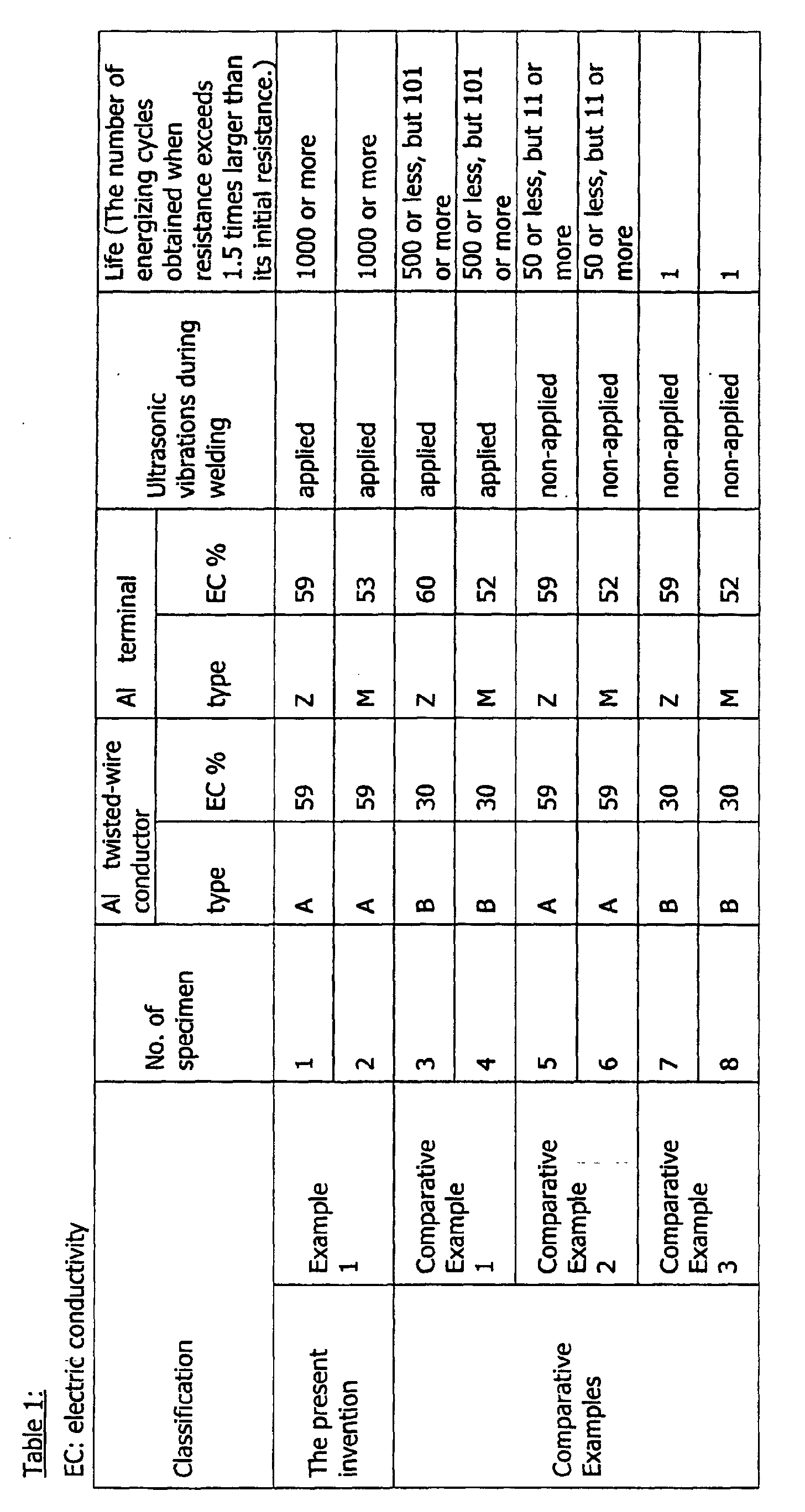
- Each of the assemblies manufactured in the example 1 and comparative example 1 to 3 underwent an energizing cycle test in which electric power of 4 kVA is turned on and off at 1, 10, 50, 100, 500 and 1000 cycles, respectively. After turning on and off at each cycle, electric resistance was measured between a certain location a on the terminal and a location b on the distribution cable, the location b being located 100 mm apart from the location a (refer to Fig. 2(a)). The life of the assemblies was measured as the number of energizing cycles obtained when the resistance exceeded an amount 1.5 times larger than its initial resistance. The results of the test are shown in Table 1.
- the assemblies according to the present invention showed excellent terminal/cable connection characteristics. After the test at 1000 cycles, those assemblies according to the present invention exhibited an electric resistance which is not more than 1.08 times larger than its initial value of electric resistance.
- the specimens of Nos. 3 and 4 manufactured in the comparative example 1 showed only a shorter life of 500 to 100 times with respect to energizing cycles, because the conductivity of the Al twisted-wire conductor was lower.
- the specimens of Nos. 5 and 6 manufactured in the comparative example 2 showed a mere shorter life of 50 to 10 times with respect to energizing cycles, because no ultrasonic vibrations were applied in the welding.
- the specimens of Nos. 7 and 8 manufactured in the comparative example 3 showed only an extremely shorter life of 1 times with respect to energizing cycles, because the Al twisted-wire conductor is lower in conductivity and no ultrasonic vibrations were applied in the welding.
- Al alloy billet was first manufactured which consists of Mg : 4.0 wt %, Mn : 0.4 wt %, Fe : 0.5 wt %, Si : 0.4 wt %, Zn : 0.25 wt % and balance made up of Al and unavoidable impurities.
- This Al alloy billet was hot-rolled into a material of which thickness is 5 mm, and then this rolled material was cold-rolled into that of a thickness of 2.3 mm. After being annealed, this cold-rolled was slit into a material of 45 mm in width, then the slit material was subjected to pressure welding and bending in this order so as to produce an Al terminal.
- This Al terminal was welded onto the foregoing Al twisted-wire conductor A with ultrasonic vibrations applied. However, the elongation of this terminal was only 18 percents, which caused a crack within the terminal in the welding operation.
- the two Al terminals Z manufactured in the example 1 were further subject to electroplating with Ni performed on the terminal at a thickness of 3 ⁇ m and to electroless plating with Ni-P alloy performed on the terminal at a thickness of 3 ⁇ m, respectively.
- Each of those Ni-plated Al terminals is welded onto the Al twisted-wire conductor A with ultrasonic vibrations applied (1400 W x 1 sec.), so that two types of assemblies were produced.
- the three Al terminals Z manufactured in the example 1 were further subject to electroplating with Ni performed on the terminal at a thickness of 10 ⁇ m, to electroless plating of Ni-P performed on the terminal at a thickness of 10 ⁇ m, and to electroplating with Sn performed on the terminal at a thickness of 3 ⁇ m, respectively.
- Those plated Al terminals were used to produce three types of assemblies in a similar way with that in the example 2.
- a 96-hours neutral salt spray test defined by JIS Z2371 was performed with each assembly manufactured in the example 2 and comparative example 5. After the spray test, the assemblies underwent the cycle test in the same way as that employed in the example 1 so that the life of each assembly was examined. For comparison, the life of terminals with no plating was also examined in the same way as above. The results of the test are shown in Table 2.
- the assemblies according to the present invention showed excellent terminal/cable connection characteristics. After the test at 1000 cycles, those assemblies according to the present invention exhibited electric resistance whose value was nearly 1.11 times larger than its initial value of electric resistance.
- the assembly according to the present invention employs a construction wherein a metal terminal is attached to an Al twisted-wire conductor employed as the conductor of a distribution cable, so that the cable is lightened.
- the Al twisted-wire conductor can be made thinner in diameter, because its conductivity is 50 % or more under IACS, providing an excellent flexibility. Thus the cable is easier to handle.
- the metal terminal is made from, preferably, an aluminum metal or aluminum alloy of which elongation is 20 % or more. Therefore, no cracks will be caused when forming the terminal and welding the terminal onto the conductor.
- This metal terminal is welded onto the Al twisted-wire terminal under the application of ultrasonic vibrations, which will cause oxide layers formed on both of the conductor and the terminal to be destroyed.
- the metal materials themselves of the conductor and the terminal come to be exposed and made to directly contact with each other, providing a superior connection characteristic with stability.
- coating Ni on the terminal is able to provide a satisfactory use even under a corrosive environment. Accordingly, the assembly has such remarkable advantages when used in industrial applications.
Landscapes
- Conductive Materials (AREA)
Abstract
Description
- the twisted-wire conductor is made of an aluminum metal or an aluminum alloy of which conductivity is 50 % or more under IACS,
- the connecting terminal connected to the twisted-wire conductor is made of a metal, and
- the twisted wire conductor and the connecting terminal are connected by pressure welding accompanied by ultrasonic vibrations.
Specifically, Fig. 1(a) shows the
The Al alloy thus composed is excellent in strength, conductivity, creep resistance, and others, so it can be used best. The Al alloy also has the advantage that its oxide layer grows at slower speeds. Thus, contact resistance among the strands of the Al twisted-wire conductor is kept lower for a longer time, providing a higher, stable conductivity in course of time.
Zr : 0.03 to 0.4 wt % and Si : 0.05 to 0.15 wt %, and the balance consists of Al and unavoidable impurities.
Mg : 0.3 to 1.8 wt %, Si : 0.15 to 1.5 wt %, Fe : 0.1 to 1.0 wt %, and Cu : 0.05 to 0.5 wt %, which can further includes one or more elements in a total content of 0.03 to 0.6 wt % selected from a group of Mn, Cr, and Ti, and the balance of which consists of Al and unavoidable impurities. This alloy has an electric conductivity of 40 % IACS or more and a high creep strength, and hence the alloy is preferably used for the metal terminal.
In the working of the alloy based on the foregoing forming methods, it is preferred that an aging treatment be performed in a proper manner in the course of the working or at the final stage of the working, so that the terminal is formed with higher conductivity and higher strength.
Mn : 0.4 wt %, Fe : 0.5 wt %, Si : 0.4 wt %, Zn : 0.25 wt % and balance made up of Al and unavoidable impurities. This Al alloy billet was hot-rolled into a material of which thickness is 5 mm, and then this rolled material was cold-rolled into that of a thickness of 2.3 mm. After being annealed, this cold-rolled was slit into a material of 45 mm in width, then the slit material was subjected to pressure welding and bending in this order so as to produce an Al terminal. This Al terminal was welded onto the foregoing Al twisted-wire conductor A with ultrasonic vibrations applied. However, the elongation of this terminal was only 18 percents, which caused a crack within the terminal in the welding operation.

Claims (8)
- An electric distributor assembly comprising a distribution cable composed of an insulation-coated twisted-wire conductor made of an aluminum metal or aluminum alloy and a connecting terminal connected to one end of said twisted wire conductor, wherein
said twisted-wire conductor is made of an aluminum metal or aluminum alloy wherein electric conductivity is 50 % or more under IACS,
said connecting terminal connected to said twisted-wire conductor is made of a metal, and
said twisted wire conductor and said connecting terminal are connected by pressure welding with ultrasonic vibrations. - The electric distributor assembly of claim 1, wherein said metal for said connecting terminal is an aluminum metal or an aluminum alloy whose elongation is 20 % or more.
- The electric distributor assembly of claim 1 or 2, wherein said aluminum alloy composing the twisted-wire conductor consists of Zr : 0.03 to 0.4 wt %, Fe : 0.05 to 0.2 wt %, and Si : 0.05 to 0.2 wt % and further includes in total 0.003 to 0.05 wt % of one or more elements selected from Be, Sr, Mg, Ti and V, and the balance consists of Al and unavoidable impurities.
- The electric distributor assembly of claim 2 or 3, wherein said aluminum alloy for said connecting terminal consists of Zr : 0.03 to 0.4 wt % and Si : 0.05 to 0.15 wt % and the balance consists of Al and unavoidable impurities.
- The electric distributor assembly of claim 2 or 3, wherein said aluminum alloy for connecting terminal consists of Mg : 0.3 to 1.8 wt %, Si : 0.15 to 1.5 wt %, Fe : 0.1 to 1.0 wt %, and Cu : 0.05 to 0.5 wt % and further includes in total 0.03 to 0.6 wt % of one or more elements selected from Mn, Cr and Ti, and the balance consists of Al and unavoidable impurities.
- The electric distributor assembly of any one of claims 1 to 5, wherein said connecting terminal is coated on a surface thereof with Ni or an Ni alloy whose main component is Ni with a thickness of 5 µm or less.
- The electric distributor assembly of claim 1, further comprising an electromagnetic shielding metal layer for covering an outer surface of the electric distributor assembly and an insulation-coated layer covering said outer surface of the metal layer.
- The electric distributor assembly of claim 7, wherein the electromagnetic shielding metal layer is composed of a reticulated member made of an aluminum metal or an aluminum alloy.
Applications Claiming Priority (3)
| Application Number | Priority Date | Filing Date | Title |
|---|---|---|---|
| JP2001057438 | 2001-03-01 | ||
| JP2001057438 | 2001-03-01 | ||
| PCT/JP2001/005348 WO2002071563A1 (en) | 2001-03-01 | 2001-06-22 | Power distribution assembly |
Publications (4)
| Publication Number | Publication Date |
|---|---|
| EP1291992A1 true EP1291992A1 (en) | 2003-03-12 |
| EP1291992A4 EP1291992A4 (en) | 2005-03-09 |
| EP1291992B1 EP1291992B1 (en) | 2007-05-16 |
| EP1291992B9 EP1291992B9 (en) | 2007-11-14 |
Family
ID=18917314
Family Applications (1)
| Application Number | Title | Priority Date | Filing Date |
|---|---|---|---|
| EP01943810A Expired - Lifetime EP1291992B9 (en) | 2001-03-01 | 2001-06-22 | Power distribution assembly |
Country Status (6)
| Country | Link |
|---|---|
| US (1) | US6573454B2 (en) |
| EP (1) | EP1291992B9 (en) |
| JP (1) | JPWO2002071563A1 (en) |
| KR (1) | KR100434617B1 (en) |
| DE (1) | DE60128468T2 (en) |
| WO (1) | WO2002071563A1 (en) |
Cited By (6)
| Publication number | Priority date | Publication date | Assignee | Title |
|---|---|---|---|---|
| EP1295956A3 (en) * | 2001-09-25 | 2003-07-02 | The Furukawa Electric Co., Ltd. | Aluminium alloy material for use in a terminal and terminal using the same |
| EP2383357A4 (en) * | 2009-01-19 | 2013-01-02 | Furukawa Electric Co Ltd | Aluminum alloy wire |
| EP2381001A4 (en) * | 2009-01-19 | 2013-01-02 | Furukawa Electric Co Ltd | Aluminum alloy wire |
| WO2015154808A1 (en) * | 2014-04-10 | 2015-10-15 | Kromberg & Schubert Gmbh | Electric conductor with a plurality of individual wires and method for the production thereof |
| DE112010000873B4 (en) | 2009-02-17 | 2019-10-10 | Yazaki Corporation | Method for connecting electrical lines |
| US10931038B2 (en) | 2018-05-11 | 2021-02-23 | Autonetworks Technologies, Ltd. | Terminal-attached electric wire and wire harness |
Families Citing this family (48)
| Publication number | Priority date | Publication date | Assignee | Title |
|---|---|---|---|---|
| JP3824809B2 (en) * | 1999-06-16 | 2006-09-20 | 古河電気工業株式会社 | Automotive power cable and terminal for the power cable |
| US6878882B2 (en) * | 2002-09-19 | 2005-04-12 | Kevin B. Larkin | Electrical cable moisture barrier with strain relief bridge |
| US6897383B2 (en) * | 2002-09-19 | 2005-05-24 | Westek Electronics, Inc. | Electrical cable moisture barrier |
| JP4383735B2 (en) * | 2002-12-13 | 2009-12-16 | 矢崎総業株式会社 | Crimp terminal |
| JP2004288625A (en) | 2003-03-06 | 2004-10-14 | Auto Network Gijutsu Kenkyusho:Kk | Automotive wires |
| WO2005091439A1 (en) * | 2004-03-23 | 2005-09-29 | Gebauer & Griller Kabelwerke Gesellschaft M.B.H. | Method for joining a connecting element to an electric conductor made of aluminium and electric conductor produced according to said method |
| US20070119562A1 (en) * | 2004-04-14 | 2007-05-31 | Gregory George R | System and method for termination of a wire rope |
| US7231957B2 (en) * | 2004-04-14 | 2007-06-19 | George Robert Gregory | System and method for termination of a wire rope |
| JP4728599B2 (en) * | 2004-06-17 | 2011-07-20 | 古河電気工業株式会社 | Aluminum conductive wire for automobile wiring and electric wire for automobile wiring |
| JP4667770B2 (en) * | 2004-06-17 | 2011-04-13 | 古河電気工業株式会社 | Aluminum conductive wire for automobile wiring and electric wire for automobile wiring |
| DE102004030784A1 (en) * | 2004-06-25 | 2006-01-19 | Leoni Ag | Electrical contact connection and method for forming such a contact connection |
| JP2006172927A (en) * | 2004-12-16 | 2006-06-29 | Yazaki Corp | Ultrasonic bonding method and ultrasonic bonding apparatus for electric wire |
| EP1688966B1 (en) * | 2005-02-03 | 2014-03-26 | Auto-Kabel Management GmbH | Electrical flat cable for motor vehicles |
| DE102006021422B8 (en) * | 2006-05-05 | 2008-06-26 | Schunk Ultraschalltechnik Gmbh | Method of making a passage or end node, and passage or end nodes |
| EP1863139A1 (en) * | 2006-06-03 | 2007-12-05 | Hirschmann Automotive GmbH | Welding of a recast connection |
| DE102006050705B4 (en) * | 2006-10-24 | 2009-01-02 | Auto-Kabel Management Gmbh | battery lead |
| DE202007013957U1 (en) | 2007-04-23 | 2007-12-20 | Kromberg & Schubert Gmbh & Co. Kg | Ladder with contact part |
| JP5219494B2 (en) * | 2007-12-20 | 2013-06-26 | 矢崎総業株式会社 | Plated terminal crimping method |
| DE102008058047B4 (en) * | 2008-11-18 | 2013-11-07 | Auto-Kabel Management Gmbh | Connection of electrical cables by means of ultrasonic welding |
| US20100164677A1 (en) * | 2008-12-29 | 2010-07-01 | Chin-Chi Yang | Fuse |
| DE102009011934B4 (en) * | 2009-03-10 | 2018-09-20 | Auto-Kabel Management Gmbh | A method of manufacturing a battery pole terminal and a battery terminal made by the method |
| DE102009053199B4 (en) * | 2009-11-06 | 2014-02-13 | Bdk Drahtzieh- Und Kunststoffaufbereitungsgesellschaft Mbh | Strand and method for its production |
| DE102009056799A1 (en) | 2009-12-03 | 2011-06-09 | Kromberg & Schubert Gmbh & Co. Kg | Thin electrical conductor i.e. aluminum cable, for motor vehicle, has three crimp connections enclosing conductor partial areas, where conductor and contact part are connected with each other by weld joint in areas by areas |
| CN102792391B (en) | 2010-03-05 | 2016-01-20 | 矢崎总业株式会社 | Flame retardant resin composition for aluminum electric wire and aluminum electric wire using same |
| DE102010020346A1 (en) * | 2010-05-12 | 2011-11-17 | Harting Electric Gmbh & Co. Kg | Electrical contact element |
| JP5723112B2 (en) | 2010-07-05 | 2015-05-27 | 矢崎総業株式会社 | Insulated wire connection structure and connection method |
| DE102010027033A1 (en) | 2010-07-14 | 2012-01-19 | Kromberg & Schubert Kg | Conductor for electrical cable in car, has contact part connected with connector having crimping connections, where conductor and contact part are connected are joined by laser welding |
| EP2625746B1 (en) | 2010-10-06 | 2017-11-01 | Sonics & Materials, Inc. | System and method for terminating aluminum conductors |
| DE102011016556B4 (en) | 2011-04-08 | 2020-02-06 | Kromberg & Schubert Kg | Electrical contact device |
| US8826533B2 (en) * | 2011-06-24 | 2014-09-09 | Delphi Technologies, Inc. | Crimp connection to aluminum cable |
| DE102011112936A1 (en) | 2011-09-13 | 2013-03-14 | Kromberg & Schubert Kg | Electrical contact device for use in motor vehicle, has electrical conductor made from aluminum and comprising end piece, and contact part connected with vehicle-specifically designed contact part designed as punching or casting part |
| CN102899535A (en) * | 2012-10-29 | 2013-01-30 | 熊科学 | Aluminum alloy material for battery connection terminal |
| DE102013201167A1 (en) * | 2013-01-24 | 2014-08-07 | Elringklinger Ag | A method of making an electrically conductive connection between an electrical lead and an electrically conductive member and assembly manufactured by the method |
| US9849268B2 (en) * | 2013-02-06 | 2017-12-26 | Biosense Webster (Israel), Ltd. | Catheter having flat beam deflection tip with fiber puller members |
| JP5971562B2 (en) * | 2013-05-31 | 2016-08-17 | 株式会社オートネットワーク技術研究所 | Short-circuit protection device for battery monitoring system |
| JP5659274B1 (en) * | 2013-07-18 | 2015-01-28 | 大電株式会社 | Connection method of metal conductor and metal terminal |
| JP6163149B2 (en) * | 2014-12-15 | 2017-07-12 | 株式会社オートネットワーク技術研究所 | Manufacturing method of electric wire with terminal |
| DE102015210458A1 (en) * | 2015-06-08 | 2016-12-08 | Te Connectivity Germany Gmbh | Method for connecting a conductor having a base metal with a copper-containing terminal element by means of welding and a connection arrangement produced thereby |
| DE102015214408C5 (en) * | 2015-07-29 | 2020-01-09 | Telsonic Holding Ag | Sonotrode, device and method for producing a welded connection |
| JP6597212B2 (en) * | 2015-11-12 | 2019-10-30 | 住友電装株式会社 | Conductive member |
| MA44561A1 (en) * | 2016-07-21 | 2019-12-31 | Univ Du Quebec A Chicoutimi | Conductive aluminum alloys with improved creep resistance |
| DE102016124583B3 (en) * | 2016-12-16 | 2018-02-15 | Auto-Kabel Management Gmbh | Joining a connection element with a stranded conductor |
| US20210344155A1 (en) * | 2018-07-20 | 2021-11-04 | Elco Enterprises, Inc. | Electrical cable having at least one consolidated end |
| JP2020030909A (en) * | 2018-08-21 | 2020-02-27 | 矢崎総業株式会社 | Junction structure of coated wire and terminal, and junction method of wire and terminal |
| CN109802340A (en) * | 2019-01-02 | 2019-05-24 | 安徽坤和电气有限公司 | A kind of high vapor-permeable type cable testing bridge |
| US11471650B2 (en) | 2019-09-20 | 2022-10-18 | Biosense Webster (Israel) Ltd. | Mechanism for manipulating a puller wire |
| JP7488151B2 (en) * | 2020-08-06 | 2024-05-21 | 古河電気工業株式会社 | Wire with crimp terminal |
| JP7688058B2 (en) * | 2023-01-23 | 2025-06-03 | 矢崎総業株式会社 | Terminal fittings and wires with terminals |
Family Cites Families (14)
| Publication number | Priority date | Publication date | Assignee | Title |
|---|---|---|---|---|
| US3717842A (en) * | 1971-02-26 | 1973-02-20 | Perfection Electrical Prod Inc | Method of connecting aluminum wire to electrical terminals |
| US3914009A (en) * | 1971-11-19 | 1975-10-21 | Southwire Co | Electrical contact device and method of preparation thereof |
| FR2501923A1 (en) * | 1981-03-13 | 1982-09-17 | Pechiney Aluminium | Ultrasonic vibration assisted crimp cable connector for stranded wires - compresses lug wings onto bared wire and onto wired insulation during or before application ultrasonic waves |
| JPS59107067A (en) * | 1982-12-08 | 1984-06-21 | Furukawa Electric Co Ltd:The | Production of heat resistant aluminum alloy conductor |
| JPH0339441A (en) * | 1989-07-06 | 1991-02-20 | Sumitomo Light Metal Ind Ltd | Aluminum alloy for vtr cylinder |
| JPH03222796A (en) * | 1990-01-30 | 1991-10-01 | Nippon Light Metal Co Ltd | Aluminum support for planographic printing plate |
| JPH0465022A (en) * | 1990-07-02 | 1992-03-02 | Sumitomo Electric Ind Ltd | Automotive wire conductor |
| JPH04301046A (en) * | 1991-03-28 | 1992-10-23 | Fujikura Ltd | Heat resisting aluminum alloy material for electrification |
| JP2850640B2 (en) * | 1992-04-28 | 1999-01-27 | 株式会社デンソー | Hybrid integrated circuit device |
| JP3127698B2 (en) * | 1994-01-27 | 2001-01-29 | 住友電装株式会社 | Wire harness splicing method |
| JP2869617B2 (en) * | 1994-11-08 | 1999-03-10 | 三菱電線工業株式会社 | Manufacturing method of aluminum alloy wire |
| JP3724033B2 (en) * | 1996-01-30 | 2005-12-07 | 住友電気工業株式会社 | High-strength, high-heat-resistant aluminum alloy and its manufacturing method, conductive wire and overhead wire |
| JP3394175B2 (en) * | 1998-01-13 | 2003-04-07 | 矢崎総業株式会社 | Termination treatment structure and termination treatment method for shielded wires |
| JP3824809B2 (en) * | 1999-06-16 | 2006-09-20 | 古河電気工業株式会社 | Automotive power cable and terminal for the power cable |
-
2001
- 2001-06-22 KR KR10-2002-7000005A patent/KR100434617B1/en not_active Expired - Fee Related
- 2001-06-22 EP EP01943810A patent/EP1291992B9/en not_active Expired - Lifetime
- 2001-06-22 JP JP2002522485A patent/JPWO2002071563A1/en active Pending
- 2001-06-22 DE DE60128468T patent/DE60128468T2/en not_active Expired - Lifetime
- 2001-06-22 WO PCT/JP2001/005348 patent/WO2002071563A1/en not_active Ceased
- 2001-11-13 US US09/993,458 patent/US6573454B2/en not_active Expired - Lifetime
Cited By (8)
| Publication number | Priority date | Publication date | Assignee | Title |
|---|---|---|---|---|
| EP1295956A3 (en) * | 2001-09-25 | 2003-07-02 | The Furukawa Electric Co., Ltd. | Aluminium alloy material for use in a terminal and terminal using the same |
| EP2383357A4 (en) * | 2009-01-19 | 2013-01-02 | Furukawa Electric Co Ltd | Aluminum alloy wire |
| EP2381001A4 (en) * | 2009-01-19 | 2013-01-02 | Furukawa Electric Co Ltd | Aluminum alloy wire |
| EP2719783A3 (en) * | 2009-01-19 | 2014-04-30 | Furukawa Electric Co., Ltd. | Aluminum alloy wire |
| US8951370B2 (en) | 2009-01-19 | 2015-02-10 | Furukawa Electric Co., Ltd. | Aluminum alloy wire material |
| DE112010000873B4 (en) | 2009-02-17 | 2019-10-10 | Yazaki Corporation | Method for connecting electrical lines |
| WO2015154808A1 (en) * | 2014-04-10 | 2015-10-15 | Kromberg & Schubert Gmbh | Electric conductor with a plurality of individual wires and method for the production thereof |
| US10931038B2 (en) | 2018-05-11 | 2021-02-23 | Autonetworks Technologies, Ltd. | Terminal-attached electric wire and wire harness |
Also Published As
| Publication number | Publication date |
|---|---|
| KR100434617B1 (en) | 2004-06-04 |
| US20020162683A1 (en) | 2002-11-07 |
| KR20030008204A (en) | 2003-01-24 |
| EP1291992A4 (en) | 2005-03-09 |
| EP1291992B1 (en) | 2007-05-16 |
| US6573454B2 (en) | 2003-06-03 |
| JPWO2002071563A1 (en) | 2004-09-30 |
| EP1291992B9 (en) | 2007-11-14 |
| WO2002071563A1 (en) | 2002-09-12 |
| DE60128468T2 (en) | 2008-01-17 |
| DE60128468D1 (en) | 2007-06-28 |
Similar Documents
| Publication | Publication Date | Title |
|---|---|---|
| US6573454B2 (en) | Electric distribution assembly | |
| JP3824809B2 (en) | Automotive power cable and terminal for the power cable | |
| EP3604579B1 (en) | Aluminium alloy material, conductive member using same, conductive component, spring member, spring component, semiconductor module member, semiconductor module component, structure member, and structure component | |
| JP4171888B2 (en) | Automotive conductor | |
| CN110914923B (en) | Covered Wire, Wire with Terminals, and Stranded Wire | |
| JPWO2005024851A1 (en) | Covered wire and automotive wire harness | |
| US11183780B2 (en) | Connection structure | |
| AT506897B1 (en) | METALLIC COMPOSITE WIRE WITH AT LEAST TWO METALLIC LAYERS | |
| JPH04230905A (en) | Copper-clad aluminum composite wire and manufacture thereof | |
| JP5365998B2 (en) | Electric wire with terminal and terminal member | |
| JP4330005B2 (en) | Aluminum conductive wire | |
| JP4041970B2 (en) | Automotive conductor | |
| JP4330003B2 (en) | Aluminum conductive wire | |
| US9412483B2 (en) | Composite wire and contact element | |
| JP4728599B2 (en) | Aluminum conductive wire for automobile wiring and electric wire for automobile wiring | |
| JP2021144805A (en) | Connection structure | |
| JP4667770B2 (en) | Aluminum conductive wire for automobile wiring and electric wire for automobile wiring | |
| JP2006004760A (en) | Aluminum conductive wire | |
| JP2003086259A (en) | Connection between aluminum stranded conductor and terminal and connection method thereof | |
| RU238748U1 (en) | ELECTRIC WIRE | |
| JPH0210525B2 (en) |
Legal Events
| Date | Code | Title | Description |
|---|---|---|---|
| PUAI | Public reference made under article 153(3) epc to a published international application that has entered the european phase |
Free format text: ORIGINAL CODE: 0009012 |
|
| 17P | Request for examination filed |
Effective date: 20021031 |
|
| AK | Designated contracting states |
Kind code of ref document: A1 Designated state(s): AT BE CH CY DE DK ES FI FR GB GR IE IT LI LU MC NL PT SE TR |
|
| A4 | Supplementary search report drawn up and despatched |
Effective date: 20050125 |
|
| RIC1 | Information provided on ipc code assigned before grant |
Ipc: 7H 02G 1/14 A Ipc: 7H 01R 43/02 B Ipc: 7H 01R 13/03 B |
|
| 17Q | First examination report despatched |
Effective date: 20050621 |
|
| GRAP | Despatch of communication of intention to grant a patent |
Free format text: ORIGINAL CODE: EPIDOSNIGR1 |
|
| RBV | Designated contracting states (corrected) |
Designated state(s): DE FR GB IT SE |
|
| GRAS | Grant fee paid |
Free format text: ORIGINAL CODE: EPIDOSNIGR3 |
|
| GRAA | (expected) grant |
Free format text: ORIGINAL CODE: 0009210 |
|
| AK | Designated contracting states |
Kind code of ref document: B1 Designated state(s): DE FR GB IT SE |
|
| REG | Reference to a national code |
Ref country code: GB Ref legal event code: FG4D |
|
| REF | Corresponds to: |
Ref document number: 60128468 Country of ref document: DE Date of ref document: 20070628 Kind code of ref document: P |
|
| PG25 | Lapsed in a contracting state [announced via postgrant information from national office to epo] |
Ref country code: SE Free format text: LAPSE BECAUSE OF FAILURE TO SUBMIT A TRANSLATION OF THE DESCRIPTION OR TO PAY THE FEE WITHIN THE PRESCRIBED TIME-LIMIT Effective date: 20070816 |
|
| ET | Fr: translation filed | ||
| PLBE | No opposition filed within time limit |
Free format text: ORIGINAL CODE: 0009261 |
|
| STAA | Information on the status of an ep patent application or granted ep patent |
Free format text: STATUS: NO OPPOSITION FILED WITHIN TIME LIMIT |
|
| 26N | No opposition filed |
Effective date: 20080219 |
|
| GBPC | Gb: european patent ceased through non-payment of renewal fee |
Effective date: 20070816 |
|
| PG25 | Lapsed in a contracting state [announced via postgrant information from national office to epo] |
Ref country code: IT Free format text: LAPSE BECAUSE OF FAILURE TO SUBMIT A TRANSLATION OF THE DESCRIPTION OR TO PAY THE FEE WITHIN THE PRESCRIBED TIME-LIMIT Effective date: 20070516 |
|
| PG25 | Lapsed in a contracting state [announced via postgrant information from national office to epo] |
Ref country code: GB Free format text: LAPSE BECAUSE OF NON-PAYMENT OF DUE FEES Effective date: 20070816 |
|
| REG | Reference to a national code |
Ref country code: FR Ref legal event code: PLFP Year of fee payment: 15 |
|
| PGFP | Annual fee paid to national office [announced via postgrant information from national office to epo] |
Ref country code: FR Payment date: 20150608 Year of fee payment: 15 |
|
| REG | Reference to a national code |
Ref country code: FR Ref legal event code: ST Effective date: 20170228 |
|
| PG25 | Lapsed in a contracting state [announced via postgrant information from national office to epo] |
Ref country code: FR Free format text: LAPSE BECAUSE OF NON-PAYMENT OF DUE FEES Effective date: 20160630 |
|
| PGFP | Annual fee paid to national office [announced via postgrant information from national office to epo] |
Ref country code: DE Payment date: 20190612 Year of fee payment: 19 |
|
| REG | Reference to a national code |
Ref country code: DE Ref legal event code: R119 Ref document number: 60128468 Country of ref document: DE |
|
| PG25 | Lapsed in a contracting state [announced via postgrant information from national office to epo] |
Ref country code: DE Free format text: LAPSE BECAUSE OF NON-PAYMENT OF DUE FEES Effective date: 20210101 |