EP1291661A1 - Procédé et dispositif de controle d'organes électriques à bord d'un véhicule - Google Patents
Procédé et dispositif de controle d'organes électriques à bord d'un véhicule Download PDFInfo
- Publication number
- EP1291661A1 EP1291661A1 EP02292182A EP02292182A EP1291661A1 EP 1291661 A1 EP1291661 A1 EP 1291661A1 EP 02292182 A EP02292182 A EP 02292182A EP 02292182 A EP02292182 A EP 02292182A EP 1291661 A1 EP1291661 A1 EP 1291661A1
- Authority
- EP
- European Patent Office
- Prior art keywords
- current
- organs
- organ
- central unit
- battery
- Prior art date
- Legal status (The legal status is an assumption and is not a legal conclusion. Google has not performed a legal analysis and makes no representation as to the accuracy of the status listed.)
- Withdrawn
Links
Images



Classifications
-
- G—PHYSICS
- G01—MEASURING; TESTING
- G01R—MEASURING ELECTRIC VARIABLES; MEASURING MAGNETIC VARIABLES
- G01R31/00—Arrangements for testing electric properties; Arrangements for locating electric faults; Arrangements for electrical testing characterised by what is being tested not provided for elsewhere
- G01R31/005—Testing of electric installations on transport means
Definitions
- the invention relates to a method and a device for control of electrically operated components on board a vehicle.
- a vehicle includes many controlled components electrically such as windshield wipers, position lights and lighting, direction indicators, radio, air conditioning, etc. To this end, each of these organs is linked to an activator controlled by the driver and / or so automatic in a decentralized or centralized mode.
- the activator is directly connected to the organ.
- control signals of the activator are transmitted to the organ to be controlled by through a central unit, for example a microprocessor.
- a centralized control allows, thanks to a central unit programming, to correlate a command manual with automatic control. For example, we can program the central unit so that the rear wiper is automatically activated when the front wiper is activated and the vehicle reverse gear is engaged.
- centralized control simplifies the architecture of the control network since it allows connect several organs to the central unit by the same circuit multiplexing control.
- the operation of the electrical components can be controlled from manual or automatic.
- Manual control called diagnostic, consists of successively activate and deactivate each organ and measure the current delivered by the battery after each activation. These measurements are compared to supply currents theoretically necessary for the proper functioning of each organ and, if the value of the current measured for an organ differs of the expected value, a malfunction of this organ is diagnostic. Manual control is long, expensive and inexpensive reliable.
- This control mode is not used for a vehicle in operation where several organs can be activated simultaneously, a measurement of the supply current cannot not be attributed specifically to the functioning of an organ. This is why, we use a self-diagnostic device to control the various parts of a vehicle operation, that is to say when the "ignition" is on.
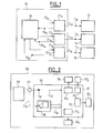
- a known control and command device represented in FIG. 1, comprises a central unit 10 (FIG. 1) supplying organs 12, 14 and 16 connected to the latter by respective connections C 12 , C 14 and C 16 transmitting the supply current I 12 , I 14 or I 16 respective to each member 12, 14 or 16.
- the emission of these currents I 12 , I 14 and I 16 is triggered by a processor 18 included in the central unit 10, for example as a function of control signals emitted by actuators (not shown) of these members 12, 14 or 16.
- This processor sends control signals 17 12 , 17 14 , 17 16 to regulating elements 21 12 , 21 14 and 21 16 .
- Each regulating element 21 j delivers, as a function of the control signal 17 j , the required intensity I j to the member j via the connection Cj.
- Diagnostic signals 19 12 , 19 14 or 19 16 emitted by each element 21 12 , 21 14 or 21 16 to the processor 18 inform the latter of the operation of each member i.
- each element 21 i checks that the intensity I j delivered to the member j corresponds to the intensity necessary for the operation of this member in accordance with the controlled operating state. For example, if the member 14 is a bulb requiring a current of 5 mA when it is activated, the element 21 14 checks that, in this case, the supply current I 14 has an intensity of 5 mA.
- the processor 18 If the processor 18 is informed by an element 21 i of the failure of an organ, it triggers a preprogrammed procedure corresponding to the type of failure identified and to the organ concerned. For example, if the processor 18 is informed of a too low consumption of the bulb 14, it informs the user of the vehicle of a possible breakdown of this bulb by means of a synthetic voice or an indicator.
- This continuous control mode has the disadvantage of requiring a large flow of diagnostic signals 19 j which the central unit must process. This flow requires the use of numerous connections and a complex processor, the control device then being of high cost.
- the invention overcomes this drawback. It relates to a method for controlling organs on board a vehicle comprising at least one battery for supplying these organs with electrical energy and a central unit to memorize the commands transmitted to them. This process is characterized in that we measure on a supply conductor connecting the battery to the organs controlled at least one representative signal the state of functioning of these organs and that compares this state to the operating state determined by commands stored in the central unit.
- the organs checked do not are not working properly and a fault is diagnosed.
- organs are checked without the transmission of diagnostic signals specific to each organ, such as the signals 19 i in FIG. 1, since all of these organs are controlled from a single signal.
- the flow of signals processed by the central unit is then greatly reduced, its operating reliability increasing by its simplification.
- this method allows a diagnostic check. automatic type, which is reliable and inexpensive.
- the signal representative of the operating state is the intensity of the current in said conductor.
- the comparison is carried out following an order from an organ. For example, if the low beams are turned on, their actuation corresponds to a predetermined current draw. Yes this predetermined current draw is detected, operation lights can be considered correct; on the other hand, if the measured current variation is significantly greater or less than an expected value, a fault is diagnosed.
- this signal representing the state of operation is the intensity of the electric current supplied by the battery and / or the variation of this intensity when a controlled organ is activated or deactivated.
- determining the intensity of the current is only taken into account when this intensity is stable over a predetermined period.
- each organ is assigned a characteristic signal transmitted on the conductor power supply, this signal being present (or absent) when the organ is activated and absent (or present) when the organ is disabled.
- this characteristic signal is a constant frequency signal, this frequency being specific to a organ.
- this process advantageously applies in the case where the vehicle comprises a centralized control network since the central unit controls the operation of electrical components and can be developed, by simple programming, to perform a comparison between expected values.
- the organs are controlled from the central unit.
- the comparison between the state of operation determined from the signal taken and the state of stored operation can be performed in the unit central in an achievement.
- the invention also relates to a vehicle comprising a battery to supply these organs with electrical energy and a central unit to memorize the commands transmitted to these last.
- This vehicle is characterized in that it includes means for implementing the method as defined above.
- the invention also relates to a control and electrical power supply device for organs on board a vehicle, comprising a battery to power these organs in electrical energy and a central unit for memorize the transmitted commands.
- a control and electrical power supply device for organs on board a vehicle, comprising a battery to power these organs in electrical energy and a central unit for memorize the transmitted commands.
- Such a device is characterized in that it includes means for setting work of the process as defined above.
- a rectangle 30 symbolically represents a vehicle equipped with a battery 29 supplying organs 32 1 , 32 2 , ... 32 j ... 32 n .
- This electrical supply is transmitted in the form of an electric current of intensity I 31 which, via a conductor C 31 , connects the battery 29 to the assembly 31 of the regulation elements 31 j of a central unit 35.
- Each of these elements 31 j subsequently feeds a member 32 j when an element 31 j receives an activation command as described later.
- a current sensor 34 on this conductor C 31 measures the intensity of the current I 31 supplied by the battery 29 to the set 31 of regulating elements, a conductor C 34 connecting this sensor 34 to a processor 36 included in the central unit 35.
- This processor 36 controls the electrical components 32 1 , 32 2 , ... 32 j ..., 32 n of the vehicle. To this end, it is connected to the assembly 31 by means of a bus C 36 transmitting control signals to the elements 31 j .
- an organ can be defined by a or several criteria (its state activated, "on”, or deactivated, "off", a level of power used, etc.). To simplify the description, it will be assumed in what follows that the functioning of an organ is defined by its state alone activation, "on” or “off”. But of course the invention is not limited to this simplified example.
- the processor 36 comprises a database B 36 in which the values of each intensity i th (32 j ) theoretically necessary for the operation of each member 32 j are stored. From this base, and knowing the state, "on” or “off", of each organ 32 j , the theoretical value of the current I th necessary to supply the organs 32 1 , 32 2 , ... 32 j ..., 32 n is determined by this processor 36 by summing the theoretical intensities necessary for the operation of the activated organs 32 j . These theoretical values can take into account various parameters such as the internal resistance of the connectors, the aging of the network, etc.
- a member 32 j is controlled when an activation or deactivation command for this member is issued by the central unit. Consequently, the latter compares the variation in the intensity of the current I 31 measured with the theoretical variation I th determined as described in the example below.
- the member 32 j requires, to operate, a current of known intensity i th (32 j ).
- the processor 36 transmits an activation command to the element 31 j for regulating this member 32 j via the conductor C 36 , this processor 36 measures the variations in the amplitude of the supply current I 31 parallel to the execution of the order.
- the intensity of the current I 31 delivered by the battery 29 increases by one value i th (32 d ).
- the processor 36 noting the equality between the measured variation of the current and the expected variation, diagnoses a correct functioning of the member 32 j .
- the processor 36 concludes that there is a failure in the device for supplying the member 32 j .
- This failure may be due to a malfunction of the battery 29, of the conductor C 31 , of the element 31 j or of the member 32 i .
- the processor 36 then triggers preprogrammed commands, for example to recommend, by means of a signal such as a synthetic voice, to the user of the vehicle to go to a garage.
- the device described in Figure 2 uses a battery 29 to power a set of organs 32 1 , 32 2 , ... 32 j ..., 32 n controlled by the same central unit 36. Any variation of the intensity I 31 is due to starting or stopping an organ 32 j .
- the network of a vehicle 40 comprises a battery 41, central units 48 and 50 and several types of organs:
- Organs 42 and 43 of a first type are directly connected to the battery 41; they don't get control signals from the central unit 48. These organs are, for example, an alternator 42 and a starter 43 controlled by actuators (not shown) according to a control mode decentralized.
- the sets of organs 46 1 and 46 2 are not directly supplied by the battery 41 but via the processor 49 of the central unit 48 - for the set of organs 46 1 - or via the processor 51 of the unit appendix 50 such as a motor unit, for all the organs 46 2 .
- the regulatory elements associated with the members 46 1j and 46 2j ' are not shown.
- Organs 44 and 45 such as a cigarette lighter and a rear view mirror which, powered by processor 51, are directly controlled by actuators not shown.
- a sensor 52 detects the current at the output of the battery 41. This sensor is used during diagnostic type checks where each member is tested successively. Thus, when an organ is activated and then deactivated, the sensor 52 measures the current I 41 supplied by the battery 41 and, by comparing the measured current with the current theoretically required during the activation of this organ, the operation of this organ.
- a sensor 52 at the outlet of the battery 41 must take into account the possible presence of organs heavy consumers of electricity and the need to diagnose the charge or discharge of the battery. In in other words, such a sensor 52 must be able to measure high currents, on the order of 100 amps, and measure the direction of these currents.
- This sensor being permanently installed in the vehicle, it allows a diagnostic check which avoids the installation of sensors by an operator as in the prior art.
- the organ tested is an organ 46 1j or 46 2j ' controlled by the processor 49, the latter can automatically carry out the diagnostic operation (activation, measurement, deactivation and diagnosis), for example in accordance with specific programming .
- organs 46 1j and 46 2j are also checked in self-diagnostic mode, that is to say independently of the functioning of other organs.
- a difficulty in the execution of this control lies in the presence of organs 42, 43, 44 and 45 which can be activated or deactivated without the processor 49 being informed thereof. The latter cannot associate a variation of the current I 41 measured by the sensor 52 with an activation or deactivation of an organ 46 1j or 46 2j since these measurements can be disturbed by the activation or deactivation of these organs 42, 43, 44 or 45.
- Another difficulty lies in the fact that the supply of the organs 46 1j and 46 2j is ensured, respectively, via the motor processor 51 and via the processor 49, themselves energy consumers.
- processors 48 and 50 The own consumption of processors 48 and 50 is symbolized by an organ 53 consuming a current of which the intensity is equal to the sum of the intensities consumed by units 48 and 50.
- two sensors 54 and 56 are then used to measure the variations in the supply currents i 461 or i 462 during a activation or deactivation of an organ 46 1j or 46 2j ' .
- the sensor 54 placed on the power supply of the assembly 46 2 measures the intensity i 462 while the sensor 56 measures the intensity i 461 .
- the variations in current caused by the activation or deactivation of members 46 1j and / or 46 2j are measured, the latter being checked by comparing the measured current variations with the expected variations.
- the processor 49 controls any modification in the operation of the organs 46 1j or 46 2j ' .
- This processor 49 is connected to the sensors 54 or 56 via the supply network to receive the current measurements made from these sensors. In another embodiment (not shown), these measurements are transmitted by a control network connecting these sensors 54 or 56 to the processor 49.
- the sensors include a current detector and a conditioner as described, for example, in the preamble to patent application FR 9900235. More specifically, a detector 60 (FIG. 4) comprises a magnetic toroid 64 surrounding a conductor 66 traversed by a current I 66 to be measured. When the current I 66 flows in the conductor 66, a magnetic field H 66 appears in the magnetic core.
- the detector 60 also includes a coil 68 surrounding the torus 64.
- a compensation current I 68 flows in the coil 68 and creates a second magnetic field H 68 opposing the first magnetic field H 66 .
- a conditioner (not shown) associated with this probe detects the voltage e, maintains the current I 68 compensating for the current I 66 and delivers a signal transmitting the measurement of the voltage.
- the same conditioner can process signals transmitted by multiple probes.
- the conditioner is connected to each probe and shares its analysis time with the various signals transmitted by each probe.
- the sensors 52, 54 and 56 can be probes such as described in connection with FIG. 4 which transmit current measurements at a conditioner located in the unit central 48. Such sharing reduces the cost of the measured.
- An operation 74 determines the theoretical variation ⁇ i (th) 461 of the current i 461 corresponding to a command 72 for activating or deactivating an organ 46 1g . To this end, this command 72, transmitted by a signal 72 74 , is recorded during an operation 74 1 .
- This memorization of the commands makes it possible to calculate the theoretical current i (th) 461 necessary for the assembly 46 1 at any time by an operation 74 2 .
- This current i (th) 461 is the sum of the currents i (th) 461i necessary for the functioning of the activated organs 46 1i . Therefore , if an organ 46 1g is activated by the command 72, the estimate of the current i (th) 461 increases by a value i 461g .
- the workload of the central unit 48 is reduced by carrying out this operation 74 2 only if the current i 461 measured is stable, this being determined during operation 70.
- An operation 74 3 modifies the value of the theoretical estimate of ⁇ i (th) 461 when particular situations arise such as the rapid activation / deactivation of an organ, for example during headlight calls. In this specific case, it is avoided that the activation command is taken into account in the calculation of the supply current because the fugitive activation of the lights prevents the current from stabilizing at an intensity corresponding to an activated mode.
- a comparison operation 76 the variation ⁇ i 461 measured is compared with the variation ⁇ i (th) 461 calculated. If this comparison shows that the two values are close enough, operation 76 diagnoses correct operation of the organ 46 1g controlled.
- the chronology of operations 70 and 74 can be such that the comparison 76 between the measured value ⁇ i 461 and the calculated value ⁇ i (th) 461 does not make sense, for example if stabilization of the supply current after a command requires a particularly long delay.
- a delay operation 74 4 is then carried out to compare the expected ⁇ i (th) 461 value with a subsequently obtained ⁇ i 461 value, as described later.
- the determination of the allowed deviation between the expected variation ⁇ i (th) 461 and the measured variation ⁇ i 461 must take into account the operating uncertainty or tolerance ⁇ I 46j of the supply current, for example due to each member 46 1j in operation.
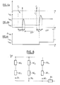
- a first delay ⁇ TR is the delay necessary for any member to receive a command transmitted to, or issued by, the central unit at an instant t; this delay ⁇ TR is thereafter considered identical for all the organs ordered.
- a first activation command C i (FIG. 6a) of an organ 46 1i
- a second command C j of activation of an organ 46 1j issued by the central unit 48 at respective instants t i and t j , are only received by the bodies concerned at instants t i + ⁇ TR and t j + ⁇ TR.
- a second transition delay ⁇ TT is required by each member to stabilize after the execution of the command.
- the current consumed by an organ is variable and the current measurements made during this period are not taken into account to control the organ.
- the member 46 1i is in transient state during the period t i + ⁇ TR to t i + ⁇ TR + ⁇ TT.
- the member 46 1j is in transient state during the period t j + ⁇ TR to t j + ⁇ TR + ⁇ TT.
- a third delay is a control duration ⁇ TF during which the measured current must be stable for its measurement to be taken into account in the control operations. Consequently, as shown in FIG. 6c, the variation in measured current ⁇ i 461 is established only after stabilization of the current after a command for a duration ⁇ TF.
- the first command C i is executed and checked before the second command is issued.
- the command C i is issued at an instant t i and the command C j is issued at an instant t j such that t j -t i > ⁇ TR + ⁇ TR + ⁇ TT + ⁇ TF.
- the control of the organs 46 1i and 46 1j is then carried out in succession
- the analysis of current measurements uses, in a preferred embodiment, a discrete Fourier transform. This transformation determines the stability of the current measured while filtering out spurious signals.
- the value of the measured current I M , during the time interval ⁇ TF, is determined from these signals S (0), S (1) ... when the measured value I M is constant during the delay ⁇ TF. In this case only the constant signal S (0) is non-zero and the value of I M is equal to the module of S (0).
- the periods ⁇ TF are detected where the measured intensity I M is constant by checking that all the signals S (i), i being non-zero, are equal to zero.
- Figure 7 is a diagram showing a current intensity (on the ordinate) as a function of time (in abscissa). This intensity, which corresponds to the functioning of a wiper, is determined every 10 ms from Last 20 measured values, a new value being measured every 10 milliseconds. The Fourier transform takes place therefore over a control period ⁇ TF of 200 ms.
- Signal processing by Fourier transform also has the advantage of filtering the measurements made by the detector 34 (Figure 2) vis-à-vis disturbances. In these disturbances being mainly irregular, they only influence the values of the signals S (1), S (2), ... and S (N), not on S (0). Now the value of the measured current is taken into consideration when these signals are zero.
- the invention is susceptible of numerous variants. For example, we can use a central unit auxiliary which does not control the electrical parts but which is informed of the order status of these organs. Since then, this central unit can control these organs in accordance with the invention from measurements of the supply current of these organs.
- each member electric is associated with oscillators so that when organ functioning, low alternating current amplitude and frequency specific to each organ circulates in a common part of the organ supply network.
- each organ is associated with a signal specific to this organ.
- FIG. 8 A device operating according to this principle is represented in FIG. 8.
- organs 80 1 , 80 2 ... 80 n are represented supplied by a current I 80 .
- Each organ 80 k is associated with an oscillator 82 k which generates an alternating current i 80k and of small amplitude compared to I 80 when the organ 80 k is activated.
- Each current i 80 is then superimposed on current I 80 so that, by performing a filtering or a spectral analysis of the supply current I 80 , each AC component of the current and the associated frequency are detected. For example, we can combine the use of Fourier Transform processing to detect the stability of a current and to perform filtering.
- an organ 80 k is then checked by checking that the appearance or disappearance of the current i 80k corresponds to the emission of commands, respectively activation or deactivation, vis-à-vis this organ.
- the failure of an organ can be detected at any time, without it being necessary to issue a command from this organ.
- this embodiment allows control permanent of the last organs whereas with the example described with figures 2 and 3 the control is carried out only during an activation or deactivation of an organ.
Landscapes
- Physics & Mathematics (AREA)
- General Physics & Mathematics (AREA)
- Electrotherapy Devices (AREA)
- Measurement And Recording Of Electrical Phenomena And Electrical Characteristics Of The Living Body (AREA)
Abstract
Description
Claims (15)
- Procédé de contrôle d'organes (32j, 461j, 462j') embarqués dans un véhicule (30, 40) comprenant au moins une batterie (29, 41) pour alimenter ces organes (32j, 461j, 462j') en énergie électrique et une unité centrale (35, 49) pour mémoriser les commandes transmises à ces derniers,
caractérisé en ce qu'on mesure sur un conducteur (C31) d'alimentation reliant la batterie (29) aux organes (32j) commandés au moins un signal représentatif de l'état de fonctionnement de ces organes (32j) et en ce qu'on compare cet état à l'état de fonctionnement déterminé par les commandes mémorisées dans l'unité centrale (35, 49, 51). - Procédé selon la revendication 1 caractérisé en ce que le signal représentant l'état de fonctionnement est l'intensité du courant (I31, i461, i462) électrique fourni par la batterie (29, 41).
- Procédé selon la revendication 1 ou 2 caractérisé en ce que le signal représentant l'état de fonctionnement est la variation de l'intensité du courant (I31, i461, i462) fourni par la batterie (29, 41) quand un organe (32j, 461j, 462j') contrôlé est activé ou désactivé.
- Procédé selon la revendication 2 ou 3 caractérisé en ce que la détermination de l'intensité du courant (I31, i461, i462) n'est prise en compte que lorsque cette intensité est stable sur une période prédéterminée.
- Procédé selon la revendication 4 caractérisé en ce que, pour détecter la stabilité du courant (I31, i461, i462), on effectue une analyse spectrale de ce dernier, par exemple par une Transformée de Fourier Discrète, le signal étant considéré stable quand les harmoniques sont nuls ou négligeables.
- Procédé selon l'une des revendications 3 à 5 caractérisé en ce que, le véhicule (30, 40) comportant des organes (42, 43, 44, 45) pour lesquels les commandes ne sont pas mémorisées dans l'unité centrale (35), l'intensité du courant (I31, i461, i462) est détectée dans une dérivation alimentant uniquement des organes contrôlés.
- Procédé selon l'une des revendications 3 à 6 caractérisé en ce qu'on prend en compte des délais prédéterminés de réception des signaux de commande par les organes (32j, 461j, 462j') commandés et des délais de stabilisation du courant (I31, i461, i462) avant de déterminer une mesure du courant, de telle sorte que si ces délais ne sont pas respectés, le contrôle est retardé ou annulé.
- Procédé selon l'une des revendications 3 à 7 caractérisé en ce qu'on prend en compte des incertitudes ou tolérances du courant (I31, i461, i462), par exemple dues aux organes en fonctionnement, de telle sorte que la variation de courant n'est considérée dans le contrôle d'un organe 32j, 461j, 462j') que si elle est supérieure à ces incertitudes ou tolérances.
- Procédé selon l'une des revendications précédentes caractérisé en ce qu'à chaque organe (80j) on affecte un signal caractéristique transmis sur le conducteur d'alimentation, ce signal étant présent (ou absent) lorsque l'organe (80j) est activé et absent (ou présent) lorsque l'organe (80j) est désactivé.
- Procédé selon la revendication 9 caractérisé en ce que le signal caractéristique est un signal à fréquence constante, cette fréquence étant propre à un organe.
- Procédé selon les revendications 5 et 10 caractérisé en ce que l'analyse spectrale est aussi utilisée pour détecter les fréquences propres aux organes.
- Procédé selon l'une des revendications précédentes caractérisé en ce qu'on commande les organes (32j, 461j, 462j' 80j) à partir de l'unité centrale.
- Procédé selon l'une des revendications précédentes caractérisé en ce que la comparaison entre l'état de fonctionnement déterminé à partir du signal prélevé et l'état de fonctionnement mémorisé est effectuée dans l'unité centrale.
- Véhicule (30, 40) comprenant une batterie (29, 41) pour alimenter ces organes (32j, 461j, 462j') en énergie électrique et une unité centrale (35, 49) pour mémoriser les commandes transmises à ces derniers, caractérisé en ce qu'il comprend des moyens pour la mise en oeuvre du procédé conforme à l'une des revendications précédentes.
- Dispositif de contrôle et d'alimentation électrique d'organes à bord d'un véhicule (30, 40), comprenant une batterie (29, 41) pour alimenter ces organes (32j, 461j, 462j') en énergie électrique et une unité centrale (35, 49) pour mémoriser les commandes transmises, caractérisé en ce qu'il comprend des moyens pour la mise en oeuvre du procédé conforme à l'une des revendications 1 à 13.
Applications Claiming Priority (2)
| Application Number | Priority Date | Filing Date | Title |
|---|---|---|---|
| FR0111558A FR2829310B1 (fr) | 2001-09-06 | 2001-09-06 | Procede et dispositif de controle d'organes electriques a bord d'un vehicule |
| FR0111558 | 2001-09-06 |
Publications (1)
| Publication Number | Publication Date |
|---|---|
| EP1291661A1 true EP1291661A1 (fr) | 2003-03-12 |
Family
ID=8867042
Family Applications (1)
| Application Number | Title | Priority Date | Filing Date |
|---|---|---|---|
| EP02292182A Withdrawn EP1291661A1 (fr) | 2001-09-06 | 2002-09-05 | Procédé et dispositif de controle d'organes électriques à bord d'un véhicule |
Country Status (2)
| Country | Link |
|---|---|
| EP (1) | EP1291661A1 (fr) |
| FR (1) | FR2829310B1 (fr) |
Citations (7)
| Publication number | Priority date | Publication date | Assignee | Title |
|---|---|---|---|---|
| US3629695A (en) * | 1969-07-31 | 1971-12-21 | Texas Instruments Inc | Prerecorded electronic tape controlled circuit testing system utilizing digital signal logic |
| FR2595829A1 (fr) * | 1986-03-17 | 1987-09-18 | Rege Nero Didier | Dispositif de securite controlant une variation anormale de courant dans un circuit electrique d'un vehicule |
| EP0398481A2 (fr) * | 1989-05-18 | 1990-11-22 | Ford Motor Company Limited | Procedure et appareil pour diagnostiquer un système de réglage électronique d'un véhicule par intermédiaire de reconnaissance de caractères |
| US5550762A (en) * | 1993-12-20 | 1996-08-27 | Doll; John A. | Diagnostic system for electronic automotive system |
| EP0762135A2 (fr) * | 1995-09-05 | 1997-03-12 | Sun Electric Uk Ltd. | Test d'unités de régulation, des batteries et similaires d'automobiles |
| US5836156A (en) * | 1994-09-16 | 1998-11-17 | Hitachi, Ltd. | Driving device of sensors and actuators |
| US6122576A (en) * | 1998-01-17 | 2000-09-19 | Robert Bosch Gmbh | Diagnosis of electrical consumers in a motor vehicle |
-
2001
- 2001-09-06 FR FR0111558A patent/FR2829310B1/fr not_active Expired - Fee Related
-
2002
- 2002-09-05 EP EP02292182A patent/EP1291661A1/fr not_active Withdrawn
Patent Citations (7)
| Publication number | Priority date | Publication date | Assignee | Title |
|---|---|---|---|---|
| US3629695A (en) * | 1969-07-31 | 1971-12-21 | Texas Instruments Inc | Prerecorded electronic tape controlled circuit testing system utilizing digital signal logic |
| FR2595829A1 (fr) * | 1986-03-17 | 1987-09-18 | Rege Nero Didier | Dispositif de securite controlant une variation anormale de courant dans un circuit electrique d'un vehicule |
| EP0398481A2 (fr) * | 1989-05-18 | 1990-11-22 | Ford Motor Company Limited | Procedure et appareil pour diagnostiquer un système de réglage électronique d'un véhicule par intermédiaire de reconnaissance de caractères |
| US5550762A (en) * | 1993-12-20 | 1996-08-27 | Doll; John A. | Diagnostic system for electronic automotive system |
| US5836156A (en) * | 1994-09-16 | 1998-11-17 | Hitachi, Ltd. | Driving device of sensors and actuators |
| EP0762135A2 (fr) * | 1995-09-05 | 1997-03-12 | Sun Electric Uk Ltd. | Test d'unités de régulation, des batteries et similaires d'automobiles |
| US6122576A (en) * | 1998-01-17 | 2000-09-19 | Robert Bosch Gmbh | Diagnosis of electrical consumers in a motor vehicle |
Also Published As
| Publication number | Publication date |
|---|---|
| FR2829310B1 (fr) | 2004-09-24 |
| FR2829310A1 (fr) | 2003-03-07 |
Similar Documents
| Publication | Publication Date | Title |
|---|---|---|
| FR2857516A1 (fr) | Appareil de surveillance de l'etat d'une batterie d'automobile | |
| FR3054772B1 (fr) | Circuit d'eclairage et feu de vehicule | |
| EP1794446A1 (fr) | Procede de controle d'une commande de demarrage/arret automatique d'un vehicule | |
| EP1797316B1 (fr) | Dispositif de controle d'un systeme de demarrage/arre automatique | |
| FR2528583A1 (fr) | Dispositif de diagnostic de circuit de charge | |
| EP2707737B1 (fr) | Procede d'estimation de l'etat de fonctionnement d'une batterie pour un systeme d'arret/relance automatique du moteur thermique d'un vehicule, capteur et systeme de gestion de batterie adaptes | |
| FR2607984A1 (fr) | Systeme de commande de regulateurs de glaces motorisees de vehicule | |
| EP1549963A1 (fr) | Procece de diagnostic concernant le branchement d une antenn e | |
| EP2311182B1 (fr) | Procede pour commander une machine electrique tournante, notamment un alternateur | |
| FR2742549A1 (fr) | Procede pour controler des appareils d'utilisation electriques dans un reseau de bord de vehicule | |
| FR2968769A1 (fr) | Procede de determination de l'etat de sante d'une batterie pour l'alimentation d'un vehicule electrique | |
| FR2920884A1 (fr) | Procede d'estimation de l'etat de sante d'une batterie embarquee dans un vehicule automobile. | |
| EP1333174A1 (fr) | Dispositif pour actionner automatiquement le démarreur du moteur thermique d'un véhicule | |
| FR2981219A1 (fr) | Methode securisee de coupure d'alimentation d'un moteur electrique et dispositif correspondant | |
| FR2829310A1 (fr) | Procede et dispositif de controle d'organes electriques a bord d'un vehicule | |
| EP2503575B1 (fr) | Procédé et dispositif de diagnostic d'un actionneur, et actionneur comportant un tel dispositif | |
| JP2005014707A (ja) | 車載バッテリの状態監視装置 | |
| EP0518716B1 (fr) | Dispositif de direction assistée électrique pour véhicule | |
| FR2869266A1 (fr) | Procede et dispositif de gestion d'un vehicule automobile equipe d'accessoires | |
| EP3361623B1 (fr) | Alterno-démarreur, véhicule automobile et procédé de commande associés | |
| FR2918760A1 (fr) | Procede et dispositif de diagnostic d'une grandeur de sortie fournie par un moteur a courant continu | |
| EP4251465B1 (fr) | Procede utilisant un compteur d'etat d'une batterie | |
| EP0919439B1 (fr) | Circuit électrique de véhicule automobiles adapté pour l'alimentation d'un microcontrôleur | |
| JPH05215052A (ja) | エンジンの自動始動装置 | |
| FR2792159A1 (fr) | Dispositif et procede de commande de l'eclairage d'un vehicule equipe d'un reseau de distribution a tension augmentee |
Legal Events
| Date | Code | Title | Description |
|---|---|---|---|
| PUAI | Public reference made under article 153(3) epc to a published international application that has entered the european phase |
Free format text: ORIGINAL CODE: 0009012 |
|
| AK | Designated contracting states |
Kind code of ref document: A1 Designated state(s): AT BE BG CH CY CZ DE DK EE ES FI FR GB GR IE IT LI LU MC NL PT SE SK TR Designated state(s): AT BE BG CH CY CZ DE DK EE ES FI FR GB GR IE IT LI LU MC NL PT SE SK TR |
|
| AX | Request for extension of the european patent |
Extension state: AL LT LV MK RO SI |
|
| 17P | Request for examination filed |
Effective date: 20030826 |
|
| AKX | Designation fees paid |
Designated state(s): AT BE BG CH CY CZ DE DK EE ES FI FR GB GR IE IT LI LU MC NL PT SE SK TR |
|
| 17Q | First examination report despatched |
Effective date: 20070509 |
|
| STAA | Information on the status of an ep patent application or granted ep patent |
Free format text: STATUS: THE APPLICATION IS DEEMED TO BE WITHDRAWN |
|
| 18D | Application deemed to be withdrawn |
Effective date: 20100113 |