EP1291548A2 - Stossdämpfer - Google Patents
Stossdämpfer Download PDFInfo
- Publication number
- EP1291548A2 EP1291548A2 EP02256207A EP02256207A EP1291548A2 EP 1291548 A2 EP1291548 A2 EP 1291548A2 EP 02256207 A EP02256207 A EP 02256207A EP 02256207 A EP02256207 A EP 02256207A EP 1291548 A2 EP1291548 A2 EP 1291548A2
- Authority
- EP
- European Patent Office
- Prior art keywords
- rebound
- passageway
- fluid
- chamber
- compression
- Prior art date
- Legal status (The legal status is an assumption and is not a legal conclusion. Google has not performed a legal analysis and makes no representation as to the accuracy of the status listed.)
- Withdrawn
Links
Images

Classifications
-
- F—MECHANICAL ENGINEERING; LIGHTING; HEATING; WEAPONS; BLASTING
- F16—ENGINEERING ELEMENTS AND UNITS; GENERAL MEASURES FOR PRODUCING AND MAINTAINING EFFECTIVE FUNCTIONING OF MACHINES OR INSTALLATIONS; THERMAL INSULATION IN GENERAL
- F16F—SPRINGS; SHOCK-ABSORBERS; MEANS FOR DAMPING VIBRATION
- F16F9/00—Springs, vibration-dampers, shock-absorbers, or similarly-constructed movement-dampers using a fluid or the equivalent as damping medium
- F16F9/32—Details
- F16F9/44—Means on or in the damper for manual or non-automatic adjustment; such means combined with temperature correction
- F16F9/46—Means on or in the damper for manual or non-automatic adjustment; such means combined with temperature correction allowing control from a distance, i.e. location of means for control input being remote from site of valves, e.g. on damper external wall
- F16F9/466—Throttling control, i.e. regulation of flow passage geometry
Definitions
- This invention relates to a shock absorber, and more particularly, the invention relates to a shock absorber having a fluid passageway in the piston rod for damping adjustment.
- shock absorbers are used in vehicles to dampen inputs from roadways. For some vehicle applications, such as snowmobiles, it may be highly desirable to provide the operator the ability to externally adjust damping characteristics of the shock absorber.
- some shock absorbers have incorporated a fluid passageway in the shock absorber piston rod to fluidly connect the rebound and compression fluid chambers.
- the rod has included a longitudinal bore with a plunger arranged within the bore.
- An adjustment knob which is accessible to the vehicle operator from the exterior of the shock absorber, cooperates with the plunger to move the plunger between various positions to control the flow of fluid through the passageway. In this manner, damping characteristics may be adjusted by the operator.
- Adjusting the plunger in the manner described above has affected the damping characteristics for both the rebound and compression strokes of the shock absorber. However, for a particular application it may be desirable to provide adjustment of the plunger that affects the damping characteristics for only one of the compression or rebound strokes. Therefore, what is needed is through the rod damping adjustment that affects the damping characteristics for one of the rebound or compression strokes.
- the present invention provides a shock absorber including a shock absorber body defining a cavity that is at least partially filled with hydraulic fluid.
- a piston is slidably arranged within the body and separates the cavity into rebound and compression fluid chambers.
- a rod is secured to the piston and includes first and second portions that are respectively adjacent to the rebound and compression chambers.
- a fluid passageway extends between the first and second portions to fluidly connect the rebound and compression chambers. In this manner, fluid is permitted to flow through the rod to provide damping characteristics in addition to those damping characteristics typically provided by the piston.
- a valve assembly which may include a one-way check valve, is arranged within the passageway for controlling the flow of fluid between the rebound and compression chambers through the passageway.
- the rod includes a longitudinal bore having an adjustable plunger arranged therein. The plunger may be adjusted by a knob to move the plunger to block at least a portion of the passageway to further control the flow of hydraulic fluid through the passageway.
- the above invention provides through the rod damping adjustment that affects the damping characteristics for one of the rebound or compression strokes.
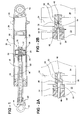
- a monotube shock absorber 10 is shown in Figure 1, although the present invention may also be used with twin tube shock absorbers.
- the shock absorber 10 is connected between a suspension and a vehicle body by upper 12 and lower 14 ends.
- the absorber 10 includes a body 16 defining a cavity 18 that is filled with hydraulic fluid.
- a piston 24 is disposed within the cavity 18 and separates compression 20 and rebound 22 fluid chambers from one another.
- a rod 26 is secured to the piston 24 typically by a nut 27 to transmit the input received from the upper end 12 to the piston 24 to move the piston 24 within the cavity 18.
- a floating piston 28 is arranged in the cavity 18 to separate the compression chamber 20 from a gas chamber 30. As is known in the art, the floating piston 28 moves within the cavity 18 to accommodate the additional volume of the rod 26 during the compression and rebound strokes.
- the piston 24 typically includes numerous valves and passages that controls the flow of fluid between the compression 20 and rebound 22 chambers to define the damping characteristics of the absorber 10 as the piston 24 moves longitudinally in the cavity 18.
- the rod 26 has included a bore 38 with a plunger 40 movable within the bore.
- a passageway 36 extends from a first portion 32 adjacent to the compression chamber 20 to a second portion 34 that is adjacent to the rebound chamber 22. Hydraulic fluid is permitted to flow between the compression 20 and rebound 22 chambers through the passageway 36.
- the adjustment knob 42 includes a cammed surface 44 that coacts with the end of the plunger 40 to move the plunger within the bore 38.
- the plunger 40 is moved within the bore 38 to manipulate an end of the plunger 40 opposite the adjustment knob 42 within the passageway 36. That is, the plunger 40 is manipulated to increase or decrease the flow of hydraulic fluid through the passageway 36 to adjust the damping characteristics provided by fluid flow through the passageway 36.
- the present invention incorporates a valve assembly 46 arranged within the passageway 36 to permit adjustments of the damping characteristics during either the compression or rebound strokes depending upon the particular application. For example, it may be desirable to provide adjustment of the absorber for the compression stroke only to accommodate a different number of passengers or passenger weights on the snowmobile.
- the passageway 36 may include a first passage 48 extending longitudinally from the first portion 32 in the direction of the plunger 40.
- the passageway 36 also includes a second passage 50 extending from the second portion 34 transverse to the first passage 48 such that the first 48 and second 50 passages meet at an intersection.
- the end of the plunger 40 is arranged within the passageway 36 at the intersection to adjust the flow therethrough as described above.
- FIGs 2A and 2B depicts an arrangement in which adjustment of the plunger 40 affects the damping characteristics of the absorber 10 during the compression stroke only.
- the valve assembly 46 may include a one-way check valve 52 arranged within the passageway 36 to prevent flow to the passageway 36 during the rebound stroke, as illustrated in Figure 2 ⁇ . Conversely, the check valve 52 permits flow through the passageway 36 during the compression stroke, as illustrated in Figure 2B.
- the check valve 52 may be arranged within the first passage 48.
- the check valve 52 includes a tapered valve seat 54 and a ball 56 seated against the valve seat 54, as shown in Figure 2A.
- the increase in fluid pressure in the compression chamber 20 forces the ball 56 from the valve seat 54 to an open position (shown in Figure 2B) to permit flow of fluid through the passageway 36.
- the rod end supporting the piston 24 may be alternatively configured as shown in Figure 2C.
- the first passage 48 may include straight walls suitable for flow during the compression stroke only as opposed to including an additional valve seat so that the rod may also be used for rebound flow configurations (shown in Figures 3A and 3B).
- valve assembly 46 may be arranged as shown in Figures 3A and 3B.
- the one-way check valve 52 is reversed from the orientation shown in Figures 2A and 2B such that the ball 56 is seated against the valve seat 54 during the compression stroke, shown in Figure 3A, so that fluid is prevented from flowing from the compression chamber 20 to the rebound chamber 22.
- the check valve 52 may include a retainer 58 to retain the ball 56 within the passageway 36. In this manner, adjustment of the plunger 40 adjusts the damping characteristics provided by fluid flow through the passageway 36 during only one of either the compression or rebound strokes.
- Figure 4 depicts an alternative construction for the rod 26.
- Insert 60a and 60b may be inserted into the first passage 48 to provide the valve seats 54 thereby eliminating difficulty in machining the valve seats in the rod 26.
- the arrangement may be used for flow during a compression stroke. That is, the ball 56 may be arranged on the other side of the retainer 58 for use during the compression stroke to provide flow through the first passage 48.
- the plunger 40 may be a screw type plunger having an end with a needle 62.
- the needle 62 may cooperate with the insert 60a to meter the flow from the second passage 50 to the first passage 48 when the plunger 40 adjusted longitudinally by an adjustment screw similar to the cam and knob discussed above.
Landscapes
- Engineering & Computer Science (AREA)
- General Engineering & Computer Science (AREA)
- Mechanical Engineering (AREA)
- Fluid-Damping Devices (AREA)
Applications Claiming Priority (2)
| Application Number | Priority Date | Filing Date | Title |
|---|---|---|---|
| US950099 | 2001-09-10 | ||
| US09/950,099 US6659239B2 (en) | 2001-09-10 | 2001-09-10 | Shock absorber through the rod damping adjustment |
Publications (2)
| Publication Number | Publication Date |
|---|---|
| EP1291548A2 true EP1291548A2 (de) | 2003-03-12 |
| EP1291548A3 EP1291548A3 (de) | 2003-12-17 |
Family
ID=25489949
Family Applications (1)
| Application Number | Title | Priority Date | Filing Date |
|---|---|---|---|
| EP02256207A Withdrawn EP1291548A3 (de) | 2001-09-10 | 2002-09-06 | Stossdämpfer |
Country Status (3)
| Country | Link |
|---|---|
| US (1) | US6659239B2 (de) |
| EP (1) | EP1291548A3 (de) |
| CA (1) | CA2398873C (de) |
Cited By (2)
| Publication number | Priority date | Publication date | Assignee | Title |
|---|---|---|---|---|
| ITFI20080178A1 (it) * | 2008-09-17 | 2010-03-18 | David Ciolini | Ammortizzatore oleodinamico |
| US8256587B2 (en) | 2007-07-18 | 2012-09-04 | Eab Engineering As | Shock absorber |
Families Citing this family (11)
| Publication number | Priority date | Publication date | Assignee | Title |
|---|---|---|---|---|
| CA2563794A1 (fr) * | 2004-04-26 | 2005-11-24 | Amortisseur Donerre | Systeme amortisseur a detente rapide et butee hydraulique de fin de course et procede d'utilisation |
| ITMI20050420A1 (it) * | 2005-03-15 | 2006-09-16 | Agostino Ferrari Spa | Dispositivo ammortizzante per elementi di arredamento |
| US10900539B2 (en) | 2005-12-30 | 2021-01-26 | Fox Factory, Inc. | Fluid damper having a damping profile favorable for absorbing the full range of compression forces, including low- and high-speed compression forces |
| US9494209B1 (en) * | 2007-06-21 | 2016-11-15 | Bill J. Gartner | Regressive hydraulic damper |
| US8978848B2 (en) | 2010-05-13 | 2015-03-17 | Durashox Technology Co., Ltd. | Apparatus for modularly adjusting shock absorber |
| JP5886287B2 (ja) * | 2010-08-12 | 2016-03-16 | グラム、カーショー、ロバートソンGraeme Kershaw Robertson | 衝撃吸収装置に対する改良 |
| CN105864347A (zh) * | 2015-01-23 | 2016-08-17 | 长春孔辉汽车科技股份有限公司 | 一种机械式可调阻尼减振器 |
| CN108119590B (zh) * | 2016-11-30 | 2019-09-27 | 同济大学 | 一种基于生物启发的阻尼器 |
| CN106678246A (zh) * | 2017-03-01 | 2017-05-17 | 长春孔辉汽车科技股份有限公司 | 可调阻尼减振器 |
| CN111828530B (zh) * | 2020-07-23 | 2022-05-20 | 北京汽车股份有限公司 | 减震器和车辆 |
| CN116592085A (zh) * | 2023-05-15 | 2023-08-15 | 西格迈股份有限公司 | 阻尼可调减振器 |
Family Cites Families (25)
| Publication number | Priority date | Publication date | Assignee | Title |
|---|---|---|---|---|
| US2592656A (en) * | 1948-11-19 | 1952-04-15 | John G Catranis | Piston and valve assembly for hydraulic control devices |
| US2825427A (en) * | 1953-08-13 | 1958-03-04 | Dumore Company | Hydraulic dashpot |
| US3003595A (en) * | 1959-03-06 | 1961-10-10 | Gabriel Co | Shock absorbers |
| US3848710A (en) * | 1971-09-13 | 1974-11-19 | Bobrick Corp | Shock absorber, piston and valve structure |
| JPS5822424Y2 (ja) * | 1978-02-06 | 1983-05-13 | トキコ株式会社 | 油圧緩衝器 |
| US4305486A (en) * | 1979-10-11 | 1981-12-15 | Interpart Corporation | Dual damping control valve shock absorber |
| GB2123922A (en) * | 1982-06-15 | 1984-02-08 | Tokico Ltd | Hydraulic damper with adjustable flow path |
| JPS59217027A (ja) * | 1983-05-20 | 1984-12-07 | Tokico Ltd | 油圧緩衝器 |
| DE3421601A1 (de) * | 1984-06-09 | 1985-12-19 | Boge Gmbh, 5208 Eitorf | Verstellbarer, hydraulischer stossdaempfer |
| EP0173020A2 (de) * | 1984-06-28 | 1986-03-05 | Stephen W. Simons | Motorradvorderradgabel mit Antikavitationssystem |
| US4593921A (en) | 1985-04-15 | 1986-06-10 | Yamaha Hatsudoki Kabushiki Kaisha | Stabilizer system for a snowmobile |
| US4826260A (en) | 1987-11-09 | 1989-05-02 | Aime Plourde | Pneumatic system for endless track vehicles |
| US4874066A (en) * | 1987-12-04 | 1989-10-17 | S.U.I. Corporation | Variable flow shock absorber and method |
| US4958706A (en) * | 1988-11-14 | 1990-09-25 | Richardson Donald G | Adjustable shock absorbers |
| DE3917064A1 (de) * | 1989-05-26 | 1990-11-29 | Bosch Gmbh Robert | Stossdaempfer ii |
| DE4016807A1 (de) * | 1989-07-21 | 1991-01-24 | Boge Ag | Regelbarer schwingungsdaempfer |
| US5094325A (en) * | 1990-06-21 | 1992-03-10 | Smith J Marlow | Vehicle shock absorber assembly |
| US5207300A (en) * | 1990-06-29 | 1993-05-04 | Boge Aktiengesellschaft | Hydraulic, adjustable vibration damper for motor vehicles |
| JP3342719B2 (ja) * | 1992-02-03 | 2002-11-11 | トキコ株式会社 | サスペンション制御装置 |
| US5667031A (en) | 1992-09-25 | 1997-09-16 | Polaris Industries Partners L.P. | Long travel suspension for tracked vehicle |
| US5370198A (en) | 1992-09-25 | 1994-12-06 | Karpik; Gerard J. | Long travel suspension for tracked vehicle |
| IT242443Y1 (it) * | 1996-11-13 | 2001-06-14 | Marzocchi Spa | Ammortizzatore idropneumatico con dispositivo di regolazione adistanza. |
| US5988330A (en) * | 1997-07-03 | 1999-11-23 | Morris; Jay | Adjustable shock absorber |
| US6360857B1 (en) * | 1999-03-19 | 2002-03-26 | Fox Factory, Inc. | Damping adjuster for shock absorber |
| US6279703B1 (en) * | 2000-05-15 | 2001-08-28 | A-Pro Cycles, Inc. | Shock absorbing adjusting structure |
-
2001
- 2001-09-10 US US09/950,099 patent/US6659239B2/en not_active Expired - Lifetime
-
2002
- 2002-08-19 CA CA002398873A patent/CA2398873C/en not_active Expired - Fee Related
- 2002-09-06 EP EP02256207A patent/EP1291548A3/de not_active Withdrawn
Non-Patent Citations (1)
| Title |
|---|
| None |
Cited By (3)
| Publication number | Priority date | Publication date | Assignee | Title |
|---|---|---|---|---|
| US8256587B2 (en) | 2007-07-18 | 2012-09-04 | Eab Engineering As | Shock absorber |
| ITFI20080178A1 (it) * | 2008-09-17 | 2010-03-18 | David Ciolini | Ammortizzatore oleodinamico |
| EP2166250A1 (de) * | 2008-09-17 | 2010-03-24 | Stefano Quirini | Öldynamischer Dämpfer |
Also Published As
| Publication number | Publication date |
|---|---|
| CA2398873A1 (en) | 2003-03-10 |
| US20030047396A1 (en) | 2003-03-13 |
| CA2398873C (en) | 2009-03-24 |
| EP1291548A3 (de) | 2003-12-17 |
| US6659239B2 (en) | 2003-12-09 |
Similar Documents
| Publication | Publication Date | Title |
|---|---|---|
| US7997394B2 (en) | Damping force adjustable fluid pressure shock absorber | |
| US5934422A (en) | Step motor actuated continuously variable shock absorber | |
| KR101326935B1 (ko) | 감쇠력 조정식 유압 완충기 | |
| JP3978707B2 (ja) | 減衰力調整式油圧緩衝器 | |
| JP3978708B2 (ja) | 減衰力調整式油圧緩衝器 | |
| US6474454B2 (en) | Damping force control type hydraulic shock absorber | |
| CA2398873C (en) | Shock absorber through the rod damping adjustment | |
| US5588510A (en) | Variable damping force shock absorber | |
| US6883650B2 (en) | Adjustable shock absorber | |
| CN100510462C (zh) | 减振器活塞组件、减振器和抑制车辆行驶变形的方法 | |
| EP1293702A2 (de) | Stossdämpfereinheit | |
| US11524544B2 (en) | Spring-absorber system with variable spring rate | |
| CN1890485A (zh) | 用于调节减振器和支架中的阻尼的电磁线圈作动连续可变伺服阀 | |
| JP2003184936A (ja) | 減衰力調整式油圧緩衝器 | |
| JPH084818A (ja) | 減衰力調整式油圧緩衝器 | |
| WO1991019914A1 (en) | Vehicle shock absorber assembly | |
| US20240286452A1 (en) | Shuttle valve shock assembly | |
| JP2000193014A (ja) | 減衰力調整式油圧緩衝器 | |
| JP2003194133A (ja) | 減衰力調整式油圧緩衝器 | |
| US7137491B2 (en) | Shock absorber non-vibrating check valve assembly | |
| JP2001012530A (ja) | 減衰力調整式油圧緩衝器 | |
| JP2002168281A (ja) | 減衰力調整式油圧緩衝器 | |
| JPH09242805A (ja) | 減衰力調整式油圧緩衝器 | |
| JP2001090768A (ja) | 減衰力調整式油圧緩衝器 | |
| JPH07269627A (ja) | 減衰力調整式油圧緩衝器 |
Legal Events
| Date | Code | Title | Description |
|---|---|---|---|
| PUAI | Public reference made under article 153(3) epc to a published international application that has entered the european phase |
Free format text: ORIGINAL CODE: 0009012 |
|
| AK | Designated contracting states |
Kind code of ref document: A2 Designated state(s): AT BE BG CH CY CZ DE DK EE ES FI FR GB GR IE IT LI LU MC NL PT SE SK TR Designated state(s): AT BE BG CH CY CZ DE DK EE ES FI FR GB GR IE IT LI LU MC NL PT SE SK TR |
|
| AX | Request for extension of the european patent |
Extension state: AL LT LV MK RO SI |
|
| PUAL | Search report despatched |
Free format text: ORIGINAL CODE: 0009013 |
|
| AK | Designated contracting states |
Kind code of ref document: A3 Designated state(s): AT BE BG CH CY CZ DE DK EE ES FI FR GB GR IE IT LI LU MC NL PT SE SK TR |
|
| AX | Request for extension of the european patent |
Extension state: AL LT LV MK RO SI |
|
| 17P | Request for examination filed |
Effective date: 20040127 |
|
| 17Q | First examination report despatched |
Effective date: 20040402 |
|
| AKX | Designation fees paid |
Designated state(s): DE ES FR GB IT |
|
| GRAP | Despatch of communication of intention to grant a patent |
Free format text: ORIGINAL CODE: EPIDOSNIGR1 |
|
| GRAS | Grant fee paid |
Free format text: ORIGINAL CODE: EPIDOSNIGR3 |
|
| RIN1 | Information on inventor provided before grant (corrected) |
Inventor name: HARBU, JULIAN Inventor name: FARR, NEIL Inventor name: VAN WONDEREN, SIMON |
|
| STAA | Information on the status of an ep patent application or granted ep patent |
Free format text: STATUS: THE APPLICATION IS DEEMED TO BE WITHDRAWN |
|
| 18D | Application deemed to be withdrawn |
Effective date: 20070403 |