EP1291457A2 - Air vortex spinning device with arrangements for assisting piecing - Google Patents
Air vortex spinning device with arrangements for assisting piecing Download PDFInfo
- Publication number
- EP1291457A2 EP1291457A2 EP02018723A EP02018723A EP1291457A2 EP 1291457 A2 EP1291457 A2 EP 1291457A2 EP 02018723 A EP02018723 A EP 02018723A EP 02018723 A EP02018723 A EP 02018723A EP 1291457 A2 EP1291457 A2 EP 1291457A2
- Authority
- EP
- European Patent Office
- Prior art keywords
- yarn
- spinning
- nozzle
- air current
- assistant
- Prior art date
- Legal status (The legal status is an assumption and is not a legal conclusion. Google has not performed a legal analysis and makes no representation as to the accuracy of the status listed.)
- Withdrawn
Links
Images




Classifications
-
- D—TEXTILES; PAPER
- D01—NATURAL OR MAN-MADE THREADS OR FIBRES; SPINNING
- D01H—SPINNING OR TWISTING
- D01H4/00—Open-end spinning machines or arrangements for imparting twist to independently moving fibres separated from slivers; Piecing arrangements therefor; Covering endless core threads with fibres by open-end spinning techniques
- D01H4/02—Open-end spinning machines or arrangements for imparting twist to independently moving fibres separated from slivers; Piecing arrangements therefor; Covering endless core threads with fibres by open-end spinning techniques imparting twist by a fluid, e.g. air vortex
-
- D—TEXTILES; PAPER
- D01—NATURAL OR MAN-MADE THREADS OR FIBRES; SPINNING
- D01H—SPINNING OR TWISTING
- D01H1/00—Spinning or twisting machines in which the product is wound-up continuously
- D01H1/11—Spinning by false-twisting
- D01H1/115—Spinning by false-twisting using pneumatic means
-
- D—TEXTILES; PAPER
- D01—NATURAL OR MAN-MADE THREADS OR FIBRES; SPINNING
- D01H—SPINNING OR TWISTING
- D01H15/00—Piecing arrangements ; Automatic end-finding, e.g. by suction and reverse package rotation; Devices for temporarily storing yarn during piecing
- D01H15/002—Piecing arrangements ; Automatic end-finding, e.g. by suction and reverse package rotation; Devices for temporarily storing yarn during piecing for false-twisting spinning machines
Definitions
- the present invention relates to a spinning device, which produces a truly twisted-like spun yarn by applying a vortex air current to a fiber bundle.
- a fiber is separated from a fiber bundle delivered from a drafting device by using the vortex air current generated by a compressed air which is jetted from an air spinning nozzle in and around a tip part of the hollow guide shaft, the fiber is made to be a truly twisted-like spun yarn after twisting the fiber to the rotating direction, and the fiber is discharged continuously by passing a yarn passage provided in a central part of the hollow guide shaft member and is wound to a winding package.
- the vortex air current is generated by the compressed air jetted from the assistant nozzle that is formed in the yarn passage of the hollow guide shaft member and is open and stretched to the direction orthogonal to the yarn delivering direction as well as the direction tangent to the yarn passage.
- the first fiber bundle is sucked into the yarn passage by making the pressure in the entrance of the yarn passage negative, and the yarn in the spinning side is discharged by making the fiber bundle the annoyed yarn by using the cooperative work of the vortex air current from the assistant nozzle and from the air spinning nozzle (this is called "yarn discharge spinning").
- a yarn end in the spinning side and a yarn in a winding side are pieced by a knotter or a splicer.
- the present invention is provided in view of the above problems, and it is an object of the present invention to secure high success rate of piecing the yarns in a spinning device for discharging the yarn by cooperative work of an air spinning nozzle and an assistant nozzle.
- a spinning device of the present invention comprising an air spinning nozzle for generating the vortex air current in and around the tip part of the hollow guide shaft member, and an assistant nozzle for generating the vortex air current in the yarn passage of the hollow guide shaft member when piecing the yarns, sucking the fiber bundle into the yarn passage, and carrying out the yarn delivering spinning
- the assistant nozzle is comprised so as to generate the vortex air current that flows to the opposite direction of the air spinning nozzle and is tilted to the downstream side to a plain orthogonal to the yarn passage.
- the vortex air current generated by the assistant nozzle to the downstream side can be stronger. Therefore, the power of delivering the yarn to the downstream side and the negative pressure can be stronger in the entrance of the yarn passage, and the first suction of the fiber bundle into the yarn passage can be surely done.
- the vortex air current from the assistant nozzle to the downstream direction and to the rotating direction are balanced suitably and yarn strength of a faced yarn which is discharged from the spinning device becomes stronger, so that the problems such as yarn breakage before piecing are prevented and the success rate in piecing the yarns can be improved.
- the tilt angle of the assistant nozzle is desired to be not smaller than 10 degrees and not higher than 35 degrees, more preferably 20 degrees.
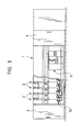
- FIG. 5 illustrates a spinning machine 1 having numerous spinning units 2 which are laid in parallel.
- the spinning machine 1 is equipped with a yarn piecing device (yarn piecing truck) 3 that is provided along the spinning units 2 so as to travel freely, a blower box 4, and a motor box 5.
- a yarn piecing device yarn piecing truck
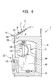
- the respective spinning units 2 are provided in a casing 6 in the main body of the spinning machine 1, and comprise a drafting device 7 provided in the vicinity of the upper end of the casing 6, a spinning part 9, which is provided in the downstream side of the drafting device 7, for spinning a fiber bundle 8 which is delivered from the drafting device 7, a yarn delivering device 11, which is provided in the downstream side of the spinning part 9, for delivering a spun yarn 10 discharged from the spinning part 9, a winding device 12, which is provided in the downstream side of the yarn delivering device 11, for winding the spun yarn 10, and a slack tube 50 and a yarn clearer 51 which are provided between the yarn delivering device 11 and the winding device 12.
- the drafting device 7 is provided for drafting a sliver 13 to make the fiber bundle 8, comprising four rollers including a back roller 14, a third roller 15, a middle roller 17 on which an apron belt 16 is bridged, and a front roller 18.
- the yarn delivering device 11 comprising a delivery roller 39 supported by the casing 6 in the main body of the spinning machine 1 and a nip roller 40 provided to be freely separated or closed to the delivery roller 39, can deliver the spun yarn 10 to the winding device 12 side after sandwiching the spun yarn 10 discharged from the spinning part 9 in between the delivery roller 39 and the nip roller 40 and driving to rotate the delivery roller 39.
- the yarn piecing device 3 comprises a truck 42 traveling on a rail 41 provided in the casing 6 in the main body of the spinning machine 1, a knotter (or a splicer, etc.) 43 provided in the truck 42, a suction pipe 44 provided to be moved up and down freely in the truck 42 and guided to a knotter 43 after sucking and catching a yarn end discharged from the spinning part 9, and a suction mouth 46 provided to be moved up and down freely in the truck 42 and guided the yarn end from a package 45 supported rotatably in the winding device 12 to the knotter 43 after sucking and grasping the yarn end.
- the slack tube 50 is provided for storing the spun yarn 10 temporarily when piecing yarns.
- the yarn clearer 51 is provided for detecting defects of the spun yarn 10.
- the spinning part 9 in the preferred embodiment of the present invention mainly comprises a spinning nozzle part 19 for applying the vortex air current to the fiber bundle 8 while passing the fiber bundle 8 delivered from the front roller 18 through the spinning part 9, a hollow guide shaft member (a spindle) 20 wherein the tip part of the fiber bundle 8 is inserted into the spinning nozzle part 19 concentrically, and a holder member 52 retaining the hollow guide shaft member 20.
- a spinning nozzle part 19 for applying the vortex air current to the fiber bundle 8 while passing the fiber bundle 8 delivered from the front roller 18 through the spinning part 9, a hollow guide shaft member (a spindle) 20 wherein the tip part of the fiber bundle 8 is inserted into the spinning nozzle part 19 concentrically, and a holder member 52 retaining the hollow guide shaft member 20.
- the nozzle part 19 comprises a needle holder 23 located in an outlet part of the front roller 18 and a casing 53 in the nozzle part wherein the needle holder 23 is fixed.
- a taper hole 54 is provided in the casing 53 in the nozzle part regarding the location in the downstream side than the needle holder 23, and a tip part 24 of the hollow guide shaft member 20 which has an almost same taper angle as the one of the taper hole 54 is inserted into the taper hole 54 concentrically and at a predetermined intervals.
- a spinning room 26 is formed between a tip surface of the hollow guide shaft member 20 and the needle holder 23, and the tip of the needle 22 is protruded in the spinning room 26 and faced to the tip surface of the hollow guide shaft member 20. Moreover, a vortex air current generating room 25 is formed between the taper hole 54 and the tip part 24.
- a plurality of air spinning nozzles 27 whose outlet end is open to the spinning room 26 is provided in the casing 53 in the nozzle part.
- These air spinning nozzles 27, comprising holes made in the casing 53 in the nozzle part, are oriented after tilting to a tangent direction of the spinning room 26 and to a downstream side to a yarn delivering direction, and get compressed air from a compressed air source (not shown in the drawings).
- these air spinning nozzles 27 jet compressed air to the spinning room 26, and generate such as the vortex air current which rotates counterclockwise in the spinning room 26, as shown in Figure 3.
- This vortex air current flows downstream spirally along with the vortex air current generating room 25 around the tip part 24 of the hollow guide shaft member 20, and is discharged from a discharge room 55 formed in the casing 53 in the nozzle part.
- the hollow guide shaft member 20 comprises an external chassis 56 having the tip part 24 and an internal chassis 57 which is engaged concentrically and fixed integrally with the external chassis 56.
- the cross sectional area of the yarn passage 29 becomes broader step by step as heading for the downstream side.
- a thick diameter part 58 whose diameter becomes broader to the downstream side than the tip part 24 of the external chassis 56 is formed in the hollow guide shaft member 20, and the thick diameter part 58 is exposed in the discharge room 55.
- a shaft retention member 59 is fitted in the casing 53 in the nozzle part to be removed freely and the thick diameter part 58 is inserted and fixed in the shaft retention member 59.
- a plurality of assistant nozzles 36 for jetting compressed air during the yarn discharging spinning is provided in the hollow guide shaft member 20.
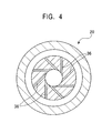
- the assistant nozzles 36 comprising holes formed by penetrating in the internal chassis 57 in the vicinity of the connecting location with the external chassis 56, are oriented to the tangent direction to the yarn passage 29 as shown in Figure 4, and generate the vortex air current which flows clockwise, that is the opposite direction to the vortex air current generated by the air spinning nozzle 27 in the yarn passage 29 as shown in Figure 3.
- a compressed air passage 37 for introducing compressed air to the assistant nozzle 36 is formed between the internal chassis 57 and the external chassis 56.
- the compressed air passage 37 is connected to a compressed air introduction hole 60 formed in the external chassis 56 and a compressed air source (not shown in the drawings) through a supply tube 38 etc. that is communicated with the compressed air introduction hole 60.
- the assistant nozzle 36 is tilted by an angle ⁇ so as to head for the downstream side to a plane P orthogonal to the yarn passage 29. More specifically, the assistant nozzle 36 is provided for jetting compressed air, heading for the downstream side of the yarn passage 29 by the angle ⁇ .
- the internal chassis 57 and the external chassis 56 are engaged together in an engage part 61 in the downstream side or the back end side of the hollow guide shaft member 20.
- a front holder 64 and a back holder 65 forming a shaft holder 63 are screwed together in a screw part 66 with sandwiching a collar part 62 formed in the external chassis 56, and retain the back side of the hollow guide shaft member 20 from the peripheral side.
- the supply tube 38 is fixed to the front holder 64.
- the holder member 52 comprises the shaft retention member 59 and the shaft holder 63.
- An tip engage part 67 formed in the tip part of the internal chassis 57 and located in the upper stream side than the assistant nozzle 36, is engaged in an engage hole 68 formed in the external chassis 56, and the contact surfaces of the tip engage part 67 and the engage hole 68 are bonded.
- the internal chassis 57 and the external chassis 56 are engaged together in the vicinity of the root of the tip part 24, and they are bonded in the peripheral surface and the tip surface of the tip engage part 67 as well as the engage part 61 located in the downstream side. Additionally, they are engaged and bonded so as not to generate gap and projection in the yarn passage 29.
- the yarn passage 29 comprises a hole 69 formed in the tip part 24 of the external chassis 56, a hole 70 provided in the upper stream side than the assistant nozzle 36 of the internal chassis 57 and having the same diameter as the one of the hole 69, and a hole 71 which has a slight larger diameter than the one of the hole 70 and provided in the downstream side of the hole 70 in the internal chassis 57 and the assistant nozzle 36.
- the assistant nozzle 36 does not jet compressed air, which is not in the working condition, and only the air spinning nozzle 27 jets compressed air, which is in the working condition.
- the vortex air current flowing counterclockwise is generated in the spinning room 26 as shown in Figure 3, and the vortex air current is discharged from a discharge room 55 with flowing spirally in the vortex air current generating room 25.
- the fiber bundle 8 or the yarn come from the front roller 18 to the yarn delivering device 11 through the guide hole 21, the spinning room 26 and the yarn passage 29, and tension is applied to the yarn as the delivering power is applied to the downstream side by the yarn delivering device 11.
- the fiber bundle 8 discharged from the front roller 18 of the drafting device 7 comes from the guide hole 21 into the spinning room 26, and the vortex air current is applied from the air spinning nozzle 27 to the fiber bundle 8.
- a residual short fiber is separated from a long fiber that becomes a core fiber in the fiber bundle 8, and the fiber bundle 8 is stirred in the vortex air current generating room 25 and twisted (see Figure 3).
- the twist tends to be propagated to the front roller 18 side, however the fiber bundle 8 is not twisted by the above twist as the needle 22 prevents the propagation.
- the needle 22 comprises a twist propagation prevention means.
- the fiber twisted as described above is made to be a truly twisted-like spun yarn whose most part becomes twining fiber sequentially, and is discharged from the outlet 34 by passing through the yarn passage 29. After that, the spun yarn 10 is wound to the winding device 12 through the yarn delivering device 11.
- the drafting device 7, the air spinning nozzle 27, and the assistant nozzle 36 are not in the working condition. Moreover, the fiber and the yarn are not existed in the downstream side of the front roller 18. Thus, the yarn tension is not also generated by the yarn delivering device 11.
- the yarn piecing device 3 is moved to the spinning unit 2, where yarns are pieced before starting yarn piecing, and next, the drafting device 7, the air spinning nozzle 27 and the assistant nozzle 36 are operated.
- the fiber bundle 8 is delivered to the spinning part 9 by the operation of the drafting device 7.
- the delivered fiber bundle 8 is entered into the spinning room 26 after passing through the guide hole 21, and the vortex air current is applied from the air spinning nozzle 27 to the fiber bundle 8.
- the fiber bundle 8 is guided by the needle 22 and delivered to the vicinity of the entrance 28 of the yarn passage 29 with the state of loose false twisting by the vortex air current. Also in this case, the twist propagation is prevented by the needle 22, the residual fiber is separated from the fiber in the core part by the vortex air current, and the fiber is swung in the vortex air current generation room 25.
- the vortex air current from the air spinning nozzle 27 in starting yarn piecing prevents the fiber bundle 8 from overswinging and the stable yarn piecing can be made, so that it is preferable that the vortex air current (the compressed air to be jetted) is made to be low pressure in a predetermined time after operating the air spinning nozzle 27, and after that, the pressure is switched to be high pressure (the nozzle pressure in the normal spinning).
- the compressed air jetted from the assistant nozzle 36 generates the vortex air current in the yarn passage 29.
- the area of the yarn passage 29 becomes broader as it goes to the downstream side and the assistant nozzle 36 is tilted to the downstream side, so that the vortex air current in the yarn passage 29 flows spirally to the downstream side.
- the assistant nozzle 36 can suck the fiber bundle into the yarn passage 29 if there is no yarn tension generated by the yarn delivering device 11 and deliver the fiber bundle to the downstream direction.
- the twining fiber can be twined around the core fiber strongly by untwisting the core fiber, and the annoyed yarn that the twining fiber is twined can be generated around the core fiber that is untwisted.
- the yarn piecing device 3 that is arrived in advance is driven and the intimid yarn 47 is sucked by the suction pipe 44 and is guided to the knotter 43.
- the assistant nozzle 36 is stopped and the yarn delivering is controlled by the yarn delivering device 11. After that, the yarn is spun in the normal spinning condition, and the truly twisted-like spun yarn is generated. Finally, the whole entertaining yarn 47 is sucked into the suction pipe 44, and the truly twisted-like spun yarn is passed to the knotter 43 substantially.
- the suction mouth 46 also sucks the yarn on the package 45 side, and the yarn is passed to the knotter 43. After that, the knotter 43 is driven, and the yarn piecing process is finished by knotting the both truly twisted-like spun yarns. In addition, the annoyed yarn 47 is eliminated by cutting yarn in piecing as described above.
- the assistant nozzle 36 is the angle ⁇ tilted to the downstream side to the plane P orthogonal to the yarn passage 29. Therefore, the stronger suction air to the downstream side can be generated in the yarn passage 29 compared with the conventional assistant nozzle orthogonal to the yarn passage 29, and the fiber bundle can be easily introduced to the yarn passage 29 as the negative pressure in the entrance 28 of the yarn passage 29 can be also stronger. Thus, the success rate of delivering yarn goes up even if the spinning speed is higher, and the success rate of piecing the yarns can also be improved.
- the problems such as breaking yarn before piecing the yarns can be prevented by strengthening the yarn strength of the annoyed yarn 47 discharged from the outlet 34 of the yarn passage 29, and the success rate of piecing the yarns can be improved. Therefore, high speed spinning can be carried out.
- Figure 8 and Figure 10 are curve charts showing the success rate (vertical axis) in piecing the yarns to the tilt angel ⁇ (horizontal axis) of the assistant nozzle 36 when changing a spinning speed V.
- Figure 8, Figure 9 and Figure 10 show the cases that the spinning speeds are 320, 350 and 370 (m/min.) respectively. It is known that the yarn delivering becomes more difficult as the fiber length of the material yarn becomes shorter and the composition number of the fiber becomes lower.
- success rate tests are performed using a carded cotton yarn (the fiber bundle is raveled and trued up to the longitudinal direction of the fiber to make the diameter even) 100% Ne 40 that is thought to be most difficult to succeed in piecing the yarns.
- the higher success rate can be acquired than before in the range of 10 degrees ⁇ ⁇ ⁇ 35 degrees at any spinning speed. Therefore, judging from the results so far obtained, the suitable angle ⁇ is not smaller than 10 degrees and not higher than 35 degrees, and the optimum angle is 20 degrees.
- the balance of the vortex air current to the rotating direction and the yarn delivering direction to the downstream side is important.
- the success rate becomes lower. This is because the vortex air current to the rotating direction becomes too small and the annoyed yarn spinning, working with the air spinning nozzle 27, cannot be carried out normally when the tilt angle ⁇ is set to be too wide, so that it is considered that the success rate of the yarn delivering spinning that is the yarn piecing success rate becomes lower.
- the assistant nozzle 36 is tilted and the tilt angle is set as described above, the balance of the both vortex air currents can be more suitable and the strong entertaining yarn can be produced even if the spinning speed is high. The yarn breakage in piecing the yarns can be prevented, the success rate of piecing the yarns can be improved, and the spinning speed can be high.
- the soft cloth can be made of the yarn generated by the high speed spinning.
- the high speed spinning can shorten the time of swinging the fiber of unit length by the vortex air current from the air spinning nozzle 27 and can be prevented the yarn from too fastening, so that the cloth as well as the generated yarn can be soften.
- the distance between the air spinning nozzle 27 and the assistant nozzle 36 (more specifically, the distance between the respective outlets) is almost same as or shorter than the average fiber length comprising the fiber bundle (see laid-open Japanese Patent Application Publication (Tokkai) No. 2001-159033). Therefore, most of the fiber can be affected by the vortex air currents from the both nozzles at the same time, the annoyed yarn to be generated can be strengthen more, and the yarn can be prevented from cutting and mistaking when piecing the yarns.
- the assistant nozzle 36 may be close to the air spinning nozzle 27 as much as possible structurally.
- the outlet of the assistant nozzle 36 may be close to the nipping point of the fiber bundle 8 of the front roller 18 as much as possible. This is because the fiber bundle 8 discharged from the front roller 18 is sucked into the spinning part 9 by the stronger suction power in the yarn delivering spinning, and the fiber loss is decreased by introducing the twist by the vortex air current from the assistant nozzle 36 to the vicinity of the front roller 18 as much as possible (the needle 22 prevents the twist introduction in the normal spinning) and by delivering a plurality of the fibers into the spinning part 9 after binding the yarn more strongly.
- the peripheral length of the thick diameter part 58 in the hollow guide shaft member 20 (the external chassis 56) is made to be longer than the average fiber length of the fiber bundle.
- the fiber swung around the hollow guide shaft member 20 can be prevented from involving each other.
- the hollow guide shaft member 20 is comprised by bonding (or sintering) the ceramic external chassis 56 and the internal chassis 57.
- the hollow guide shaft member 20 has to be exchanged altogether according to the spinning condition of yarn type and yarn count if the hollow guide shaft member 20 is comprised as one, many parts are needed according to the condition and the conventional hollow guide shaft causes to increase the number of the parts to be prepared, to waste parts management, and to add cost.
- the hollow guide shaft member 20 can be separated for solving the above problems.
- the hollow guide shaft member 20 comprises a former external chassis 75 corresponding to the former part (the upstream side) of the external chassis 56, a rear external chassis 76 corresponding to the integration of the last half (downstream side) of the external chassis 56 and the shaft holder 63, and an internal chassis 77 corresponding to the internal chassis 57.
- the former external chassis 75 includes the tip part 24, the hole 69, and the engaged hole 68, etc. as described above.
- the internal chassis 77 includes the holes 70, 71, and the assistant nozzle 36, etc. as described above.
- the rear external chassis 76 including the compressed air introduction hole 60 as described above, is connected to the supply tube 38.
- the same code is numbered in the Figures.
- the engage hole 68 of the former external chassis 75 and the tip engage part 67 of the inner chassis 77 are engaged each other in the vicinity of the root of the tip part 24. However, the engage hole 68 and the tip engage part 67 are not bonded and they can be separated.
- An 0-ring 78 is placed as the seal member and sealed in this engage part for preventing the air leakage between the yarn passage 29 and the compressed air passage 37.
- the former external chassis 75 and the rear external chassis 76 are also engaged each other. More specifically, an engage tube part 79, being formed in the protruding manner in the former end surface of the rear external chassis 76, is engaged in the inner side of the former external chassis 75.
- An 0-ring 80 used as the elastic member, lies between the back end surface (the downstream side) of the former external chassis 75 and the former end surface (the upstream side) of the rear external chassis 76.
- An insert hole 81 is provided in the shaft retention member 59 for inserting the former external chassis 75 and the rear external chassis 76 freely, and a collar part 82 is provided in the former end part of the insert hole 81 for regulating the insert position by engaging with the former external chassis 75.
- the internal chassis 77 and the rear external chassis 76 are also engaged and connected each other. More specifically, an engage part 83 whose diameter becomes a little bit wider, being formed in the rear end part of the internal chassis 77, is engaged with an engage hole 84 of the rear external chassis 76.
- the diameter of the outlet 34 in the rear part of the engage hole 84 is smaller than the one of the engage part 83, and a collar part 85 formed in the inner peripheral side in a protruding manner can push the internal chassis 77 forward.
- An 0-ring 86 provided as an elastic member, lies in between the collar part 85 and the internal chassis 77.
- a bolt 87 is inserted into the rear external chassis 76 from backside, and the bolt 87 is screwed into a screw hole 88 formed in the shaft retention member 59.
- the hollow guide shaft member 20 is assembled as follows.
- the former external chassis 75 fixing the 0-ring 78 is inserted into the insert hole 81 of the shaft retention member 59 from backside in advance, and the former external chassis 75 is fixed in the shaft retention member 59.
- the tip engage part 67 of the internal chassis 77 is engaged with the engage hole 68 of the former external chassis 75, and the internal chassis 77 is fixed in the former external chassis 75.
- the rear external chassis 76 fixing the 0-ring 80 in advance is inserted into the insert hole 81 from backside and engaged with the former external chassis 75, and the rear external chassis 76 is fixed in the shaft retention member 59 and the former external chassis 75.
- the bolt 87 is fastened.
- the former external chassis 75 and the internal chassis 77 are also pushed forward through the 0-rings 80, 86.
- the former external chassis 75 is positioned to the shaft direction by bumping into the collar part 82, and the internal chassis 77 is positioned to the shaft direction as the tip surface of the tip engage part 67 is bumped into the forward end surface (base) of the engage hole 68 in the former external chassis 75.
- the former external chassis 75 is contacted with the collar part 82 directly by a predetermined contact pressure, and the internal chassis 77 is also connected with the forward end surface of the engage hole 68 of the former external chassis 75 directly by a predetermined contact pressure.
- the contact parts are likely to be broken when a sizable pressure is placed on the contact parts.
- the contact parts are prevented from breaking by using the 0-rings 80, 86. More specifically, the power pressured by the rear external chassis 76 is loosen by the 0-rings 80, 86, and the power that is designed in advance can be applied to the former external chassis 75 and the internal chassis 77. Therefore, the excessive contact pressure in the contact part can be prevented, and the breakage in the contact part can be also prevented in advance.
- the 0-rings 80, 86 can also prevent air leakage.
- the hollow guide shaft member 20 is not comprised as one but is divided into the former external chassis 75, the rear external chassis 76, and the internal chassis 77, and they can be assembled and dismounted, so that the respective parts can be exchanged.
- the combination of the respective parts can be changed when the difference of the spinning condition including yarn type and count is occurred, the parts are not needed to be prepared respectively for every condition. Therefore, the number of the parts can be reduced, the parts management can be efficient, and the cost can be reduced.
- the hollow guide shaft member 20 can be disassembled easily even if the internal passage (the assistant nozzle 36, the yarn passage 29, etc.) is choked suddenly, the spinning machine can be easily maintained.
- the other operation and effect are same as the ones in the preferred embodiment of the present invention.
- the assistant nozzle might be close to the air spinning nozzle as much as possible.
- the assistant nozzle is arranged in the inner part in the tip part of the hollow guide shaft member generally, and it is difficult to process the assistant nozzle.
- the internal chassis 57, 77 wherein the assistant nozzle 36 is provided are the divided added parts. As the tip parts of the divided added parts are inserted and engaged with the external chassis 56 or the former external chassis 75, the assistant nozzle 36 can be easily processed and has access to the air spinning nozzle 27 as much as possible.
- the present invention is not limited to the embodiments as described above.
- the rotating direction of the assistant nozzle 36 can be same as the rotating direction of the air spinning nozzle 27. However, it is more preferable to adopt the opposite case for the effect.
- the member except the needle 22 can be used for preventing the propagation of the twist to the upstream side.
- the present invention demonstrates the following advantages. (1) The success rate of yarn discharge spinning and yarn piecing can be improved even in the case of high speed spinning. (2) Spinning speed can be higher, which leads to make soft cloth.
Landscapes
- Engineering & Computer Science (AREA)
- Mechanical Engineering (AREA)
- Textile Engineering (AREA)
- Spinning Or Twisting Of Yarns (AREA)
Abstract
Description
Claims (3)
- A spinning device comprising:an air spinning nozzle for generating vortex air current in and around a tip part of a hollow guide shaft member; and
an assistant nozzle for generating the vortex air current in the yarn passage of the hollow guide shaft member when piecing yarns, sucking the fiber bundle into the yarn passage, and carrying out the yarn delivering spinning;
wherein the assistant nozzle is comprised so as to generate the vortex air current that flows to the opposite direction of the air spinning nozzle and is tilted to the downstream side to a plain orthogonal to the yarn passage. - A spinning device as in claim 1, wherein the tilt angle of the assistant nozzle is not smaller than 10 degrees and not higher than 35 degrees.
- A spinning device as in claim 2, wherein the tilt angle of the assistant nozzle is 20 degrees.
Applications Claiming Priority (4)
| Application Number | Priority Date | Filing Date | Title |
|---|---|---|---|
| JP2001269015 | 2001-09-05 | ||
| JP2001269015 | 2001-09-05 | ||
| JP2001278407A JP2003155630A (en) | 2001-09-05 | 2001-09-13 | Spinning frame |
| JP2001278407 | 2001-09-13 |
Publications (2)
| Publication Number | Publication Date |
|---|---|
| EP1291457A2 true EP1291457A2 (en) | 2003-03-12 |
| EP1291457A3 EP1291457A3 (en) | 2003-07-23 |
Family
ID=26621708
Family Applications (1)
| Application Number | Title | Priority Date | Filing Date |
|---|---|---|---|
| EP02018723A Withdrawn EP1291457A3 (en) | 2001-09-05 | 2002-08-21 | Air vortex spinning device with arrangements for assisting piecing |
Country Status (3)
| Country | Link |
|---|---|
| EP (1) | EP1291457A3 (en) |
| JP (1) | JP2003155630A (en) |
| CN (1) | CN1407153A (en) |
Cited By (10)
| Publication number | Priority date | Publication date | Assignee | Title |
|---|---|---|---|---|
| WO2006063482A1 (en) * | 2004-12-15 | 2006-06-22 | Maschinenfabrik Rieter Ag | Spin box comprising a replaceable spindle |
| EP1826299A3 (en) * | 2006-02-28 | 2009-12-23 | Murata Kikai Kabushiki Kaisha | Spinning device and spinning method |
| WO2014041412A3 (en) * | 2012-09-14 | 2014-05-22 | Maschinenfabrik Rieter Ag | Spinning station of a roving machine |
| JP2014522919A (en) * | 2011-07-01 | 2014-09-08 | マシーネンファブリク リーター アクチェンゲゼルシャフト | A roving machine for producing roving yarn and a method of preparing and spinning a sliver |
| CN105113065A (en) * | 2015-09-25 | 2015-12-02 | 俞升洋 | Textile airflow twisting device with heat dissipation function |
| CN105113063A (en) * | 2015-09-25 | 2015-12-02 | 浦江特捷锁业有限公司 | Textile airflow twisting device with speed regulating function |
| CN105568455A (en) * | 2016-03-09 | 2016-05-11 | 苏州华策纺织科技有限公司 | Automatic connector for broken yarn |
| EP2573223A3 (en) * | 2011-09-21 | 2017-01-18 | Murata Machinery, Ltd. | Pneumatic spinning device, spinning unit, spinning machine, and pneumatic spinning method |
| US20220195637A1 (en) * | 2020-12-18 | 2022-06-23 | Saurer Intelligent Technology AG | Method for Monitoring the Spinning Process on a Spinning Device, Spinning Position of an Air-Spinning Machine and Spinning Device |
| CN117364320A (en) * | 2023-11-24 | 2024-01-09 | 苏州京正新材料科技有限公司 | Vortex spinning fancy yarn and production process thereof |
Families Citing this family (16)
| Publication number | Priority date | Publication date | Assignee | Title |
|---|---|---|---|---|
| DE10353317B4 (en) * | 2003-11-10 | 2013-06-27 | Wilhelm Stahlecker Gmbh | Method and device for restoring a previously interrupted spinning process |
| JP2008510891A (en) * | 2004-08-20 | 2008-04-10 | マシーネンファブリク リーター アクチェンゲゼルシャフト | Spindle with injector passage and method for yarn splicing in an air jet spinning machine |
| DE102005022187A1 (en) * | 2005-05-13 | 2006-11-16 | Saurer Gmbh & Co. Kg | Air spinning to produce high quality product uses an auxiliary thread which is cast off to allow knotting and splicing of newly spun thread with the upper thread |
| DE102006047120A1 (en) * | 2005-11-28 | 2007-05-31 | Wilhelm Stahlecker Gmbh | Air jet unit for producing a spun yarn |
| DE102007009074A1 (en) * | 2007-02-24 | 2008-08-28 | Oerlikon Textile Gmbh & Co. Kg | spinning device |
| DE102008006379A1 (en) * | 2008-01-29 | 2009-07-30 | Oerlikon Textile Gmbh & Co. Kg | Air-jet spinning device for use in production of yarn, has cladding gap downstream to plane, in which air flow initially withdrawing from nozzles impinges housing part surface, where gap width suddenly increases and is in specific range |
| DE102008050874A1 (en) * | 2008-09-29 | 2010-04-01 | Wilhelm Stahlecker Gmbh | Air jet spinning unit with spindle-shaped component |
| JP5333987B2 (en) * | 2008-12-19 | 2013-11-06 | 村田機械株式会社 | Pneumatic spinning machine |
| JP2010174405A (en) * | 2009-01-29 | 2010-08-12 | Murata Machinery Ltd | Yarn end catching device and spinning machine including the same |
| JP2013067882A (en) * | 2011-09-21 | 2013-04-18 | Murata Mach Ltd | Yarn winding machine, and method of producing spun yarn |
| CN102618973B (en) * | 2012-03-01 | 2013-03-27 | 江阴市华方新技术科研有限公司 | Spinning nozzle structure |
| CN102828289B (en) * | 2012-09-18 | 2014-11-05 | 东华大学 | Low-fiber falling air vortex spinning device |
| CH709756A1 (en) * | 2014-06-13 | 2015-12-15 | Rieter Ag Maschf | Spinneret for a spinning machine and air jet spinning machine with a corresponding spinneret. |
| CN105088439A (en) * | 2015-09-25 | 2015-11-25 | 郑世浦 | Dust-proof airflow twisting device with filter screen for spinning |
| CN105088435A (en) * | 2015-09-25 | 2015-11-25 | 杨田花 | Airflow bunching device for spinning |
| CN112127029A (en) * | 2020-09-24 | 2020-12-25 | 陕西华燕航空仪表有限公司 | A spinning and twisting device |
Family Cites Families (3)
| Publication number | Priority date | Publication date | Assignee | Title |
|---|---|---|---|---|
| DE3418322A1 (en) * | 1984-05-17 | 1985-11-21 | W. Schlafhorst & Co, 4050 Mönchengladbach | AIR SPIDER AND AIR SPIDER |
| JPH07113166B2 (en) * | 1991-09-04 | 1995-12-06 | 村田機械株式会社 | Spinning equipment |
| EP1072702B1 (en) * | 1999-07-28 | 2004-03-31 | Murata Kikai Kabushiki Kaisha | Spinning device and method |
-
2001
- 2001-09-13 JP JP2001278407A patent/JP2003155630A/en not_active Withdrawn
-
2002
- 2002-08-21 EP EP02018723A patent/EP1291457A3/en not_active Withdrawn
- 2002-09-04 CN CN 02132279 patent/CN1407153A/en active Pending
Cited By (13)
| Publication number | Priority date | Publication date | Assignee | Title |
|---|---|---|---|---|
| WO2006063482A1 (en) * | 2004-12-15 | 2006-06-22 | Maschinenfabrik Rieter Ag | Spin box comprising a replaceable spindle |
| EP1826299A3 (en) * | 2006-02-28 | 2009-12-23 | Murata Kikai Kabushiki Kaisha | Spinning device and spinning method |
| JP2014522919A (en) * | 2011-07-01 | 2014-09-08 | マシーネンファブリク リーター アクチェンゲゼルシャフト | A roving machine for producing roving yarn and a method of preparing and spinning a sliver |
| EP2573223A3 (en) * | 2011-09-21 | 2017-01-18 | Murata Machinery, Ltd. | Pneumatic spinning device, spinning unit, spinning machine, and pneumatic spinning method |
| US9677197B2 (en) | 2012-09-14 | 2017-06-13 | Maschinenfabrik Rieter Ag | Spinning station of a spinning preparation machine |
| WO2014041412A3 (en) * | 2012-09-14 | 2014-05-22 | Maschinenfabrik Rieter Ag | Spinning station of a roving machine |
| CN105113065A (en) * | 2015-09-25 | 2015-12-02 | 俞升洋 | Textile airflow twisting device with heat dissipation function |
| CN105113063A (en) * | 2015-09-25 | 2015-12-02 | 浦江特捷锁业有限公司 | Textile airflow twisting device with speed regulating function |
| CN105568455A (en) * | 2016-03-09 | 2016-05-11 | 苏州华策纺织科技有限公司 | Automatic connector for broken yarn |
| CN105568455B (en) * | 2016-03-09 | 2018-03-27 | 苏州华策纺织科技有限公司 | One kind broken string automatic connector |
| US20220195637A1 (en) * | 2020-12-18 | 2022-06-23 | Saurer Intelligent Technology AG | Method for Monitoring the Spinning Process on a Spinning Device, Spinning Position of an Air-Spinning Machine and Spinning Device |
| US11926934B2 (en) * | 2020-12-18 | 2024-03-12 | Saurer Intelligent Technology AG | Method for monitoring the spinning process on a spinning device, spinning position of an air-spinning machine and spinning device |
| CN117364320A (en) * | 2023-11-24 | 2024-01-09 | 苏州京正新材料科技有限公司 | Vortex spinning fancy yarn and production process thereof |
Also Published As
| Publication number | Publication date |
|---|---|
| JP2003155630A (en) | 2003-05-30 |
| CN1407153A (en) | 2003-04-02 |
| EP1291457A3 (en) | 2003-07-23 |
Similar Documents
| Publication | Publication Date | Title |
|---|---|---|
| US5511373A (en) | Method and apparatus for piecing a sliver and at least one of a leading yarn and a bobbin yarn | |
| JP3183607B2 (en) | Fiber bundling method and double apron drawing apparatus used therein | |
| JP4062869B2 (en) | Core yarn manufacturing apparatus and core yarn manufacturing method | |
| JP2003155630A (en) | Spinning frame | |
| JP5526915B2 (en) | Pneumatic spinning device and spinning machine | |
| JPH07122167B2 (en) | Yarn splicing method for spinning device | |
| JP2930010B2 (en) | Spinning machine piecing method and apparatus | |
| EP1072702B1 (en) | Spinning device and method | |
| JP3064951B2 (en) | Threader | |
| EP1316631A1 (en) | Spinning device and spinning method | |
| US4958487A (en) | Apparatus for producing spun yarn | |
| US4674274A (en) | Apparatus for manufacturing spun yarn | |
| JPH01118628A (en) | Production device for spun yarn | |
| JP5515933B2 (en) | Pneumatic spinning device and spinning machine | |
| JP2002363834A (en) | Apparatus for manufacturing core yarn | |
| JP2008517166A (en) | Method for preparing a splicing operation in an air jet spinning device | |
| CN213327994U (en) | Hollow guide shaft body and hollow guide unit | |
| JP3341726B2 (en) | Spinning equipment | |
| JP3551872B2 (en) | Spinning equipment | |
| JP3341732B2 (en) | Pneumatic spinning apparatus and splicing method thereof | |
| JP2005501184A (en) | Spinning machine method | |
| JP2003278034A (en) | Spinning device | |
| JP2001192938A (en) | Spinning apparatus and spinning method | |
| EP0068507A2 (en) | Apparatus for making fasciated spun yarn | |
| JPH0619572Y2 (en) | Spinning equipment |
Legal Events
| Date | Code | Title | Description |
|---|---|---|---|
| PUAI | Public reference made under article 153(3) epc to a published international application that has entered the european phase |
Free format text: ORIGINAL CODE: 0009012 |
|
| AK | Designated contracting states |
Kind code of ref document: A2 Designated state(s): AT BE BG CH CY CZ DE DK EE ES FI FR GB GR IE IT LI LU MC NL PT SE SK TR Designated state(s): AT BE BG CH CY CZ DE DK EE ES FI FR GB GR IE IT LI LU MC NL PT SE SK TR |
|
| AX | Request for extension of the european patent |
Extension state: AL LT LV MK RO SI |
|
| PUAL | Search report despatched |
Free format text: ORIGINAL CODE: 0009013 |
|
| AK | Designated contracting states |
Designated state(s): AT BE BG CH CY CZ DE DK EE ES FI FR GB GR IE IT LI LU MC NL PT SE SK TR |
|
| AX | Request for extension of the european patent |
Extension state: AL LT LV MK RO SI |
|
| 17P | Request for examination filed |
Effective date: 20040119 |
|
| AKX | Designation fees paid |
Designated state(s): CH DE LI |
|
| 17Q | First examination report despatched |
Effective date: 20041012 |
|
| STAA | Information on the status of an ep patent application or granted ep patent |
Free format text: STATUS: THE APPLICATION HAS BEEN WITHDRAWN |
|
| 18W | Application withdrawn |
Effective date: 20050317 |