EP1291209A2 - Ventilator - Google Patents
Ventilator Download PDFInfo
- Publication number
- EP1291209A2 EP1291209A2 EP02256195A EP02256195A EP1291209A2 EP 1291209 A2 EP1291209 A2 EP 1291209A2 EP 02256195 A EP02256195 A EP 02256195A EP 02256195 A EP02256195 A EP 02256195A EP 1291209 A2 EP1291209 A2 EP 1291209A2
- Authority
- EP
- European Patent Office
- Prior art keywords
- mode
- intermediate gear
- ventilator according
- cam groove
- ventilator
- Prior art date
- Legal status (The legal status is an assumption and is not a legal conclusion. Google has not performed a legal analysis and makes no representation as to the accuracy of the status listed.)
- Granted
Links
Images


Classifications
-
- B—PERFORMING OPERATIONS; TRANSPORTING
- B60—VEHICLES IN GENERAL
- B60H—ARRANGEMENTS OF HEATING, COOLING, VENTILATING OR OTHER AIR-TREATING DEVICES SPECIALLY ADAPTED FOR PASSENGER OR GOODS SPACES OF VEHICLES
- B60H1/00—Heating, cooling or ventilating devices
- B60H1/34—Nozzles; Air-diffusers
- B60H1/345—Nozzles; Air-diffusers with means for adjusting divergence, convergence or oscillation of air stream
-
- B—PERFORMING OPERATIONS; TRANSPORTING
- B60—VEHICLES IN GENERAL
- B60H—ARRANGEMENTS OF HEATING, COOLING, VENTILATING OR OTHER AIR-TREATING DEVICES SPECIALLY ADAPTED FOR PASSENGER OR GOODS SPACES OF VEHICLES
- B60H1/00—Heating, cooling or ventilating devices
- B60H1/34—Nozzles; Air-diffusers
- B60H2001/3471—Details of actuators
- B60H2001/3478—Details of actuators acting on additional damper doors
Definitions
- the present invention relates to a ventilator for adjusting the direction of wind blown out from an air outlet.
- the ventilator in the publication includes an air outlet, a support member and a link.
- the air outlet is provided with a plurality of turnable louvers which are parallel to each other.
- the support member is movable in a cross direction.
- the link is supported by the support member, and is movable in a direction perpendicular to the support member.
- An interlock shaft projected from the louver is engaged with a guide groove provided in the link. If a knob provided on a central louver is operated in a lateral direction, the direction of a parallel wind blown out from the air outlet can be adjusted in the lateral direction.
- a selector is operated vertically, the support member is moved in a back-and-forth direction, and a position of the interlock shaft is adjusted by the guide groove formed in the link. With this operation, a spot air flow mode, a diffusing air flow mode and an ordinal parallel air flow mode can be selected.
- the present invention has been accomplished to resolve the conventional problems. It is an object of the present invention to continuously select the normal mode which adjusts wind direction of the parallel wind and the specific mode which collects or diffuse the wind using a single operating apparatus. It is another object of the invention to provide a ventilator capable of closing the air outlet by means of fins, and to enhance the operatability and the appearance.
- the first aspect of the present invention provides a ventilator for adjusting a wind direction having a case, a plurality of fins being operated in a normal mode in which the wind direction is adjusted by turning the fins in parallel to each other, and in a specific mode in which the wind direction is collected or diffused, and a mode selector for continuously selecting the normal mode and the specific mode, wherein the mode selector has a normal operating region and a specific operating region, and the normal mode is performed in the normal operating region and the specific mode is performed in the specific operating region.
- the normal mode can adjust the wind direction of the parallel wind blown out from the air outlet.
- the specific mode can diffuse the wind blown out from the air outlet and blow the wind toward the passenger, or can collect and blow the wind. Operatability is remarkably enhanced as compared with other conventional operating apparatus in which the normal mode and the specific mode are selected separately.
- the second aspect of the present invention provides a ventilator according to the first aspect of the present invention, wherein the specific operating region is provided next to the normal operating region.
- the third aspect of the present invention provides a ventilator according to the first aspect of the present invention, wherein the mode selector comprises an operation dial, an intermediate gear which is rotated by the operation of operation dial, and a slide link which is engaged with a cam groove formed on the intermediate gear and is moved in a cross direction, and the slide link is moved from the normal operating region to the specific operating region via the intermediate gear such that the normal mode and the specific mode are continuously selected.
- the mode selector comprises an operation dial, an intermediate gear which is rotated by the operation of operation dial, and a slide link which is engaged with a cam groove formed on the intermediate gear and is moved in a cross direction, and the slide link is moved from the normal operating region to the specific operating region via the intermediate gear such that the normal mode and the specific mode are continuously selected.
- the third aspect it is possible to continuously select the normal mode and the specific mode with a single operation dial. Therefore, as compared with other conventional operating apparatus, operatability is remarkably enhanced. Since the rotation of the operation dial is transmitted to a slide link by a gear, the action of the mode selector becomes smooth, and it is possible to easily select the normal mode and the specific mode by a smaller operation force. Since the mode selector can be constituted by a small number of parts, the apparatus can be formed compactly, thus the size of the ventilator can be reduced. And workability of assembling can be improved.
- a ventilator 1 has a polygonal columnar case 2 whose front face is opened as an opening 2a.
- the case 2 is mounted inside an air outlet which is opened above an instrument panel for example such that the opening 2a is directed rearward of the vehicle (toward a passenger).
- a plurality of fins 3 are horizontally provided at distances from one another in a vertical direction.
- a shaft pin 3a projected from one end of each fins 3 is rotatably pivoted into a pin hole 2c formed in one of side plates 2b of the case 2.
- a shaft pin 3a and a connection pin 3b are projected from the other end of each of the fins 3.
- the shaft pin 3a is rotatably pivoted into a pin hole 4a of a spacer 4 provided along an opening edge of the other side plate 2b.
- a finisher 8 is mounted to the opening 2a of the case 2.
- the finisher 8 is formed by a plate which is curved in the vertical direction.
- An opening 8a is formed on a front side of the fins 3, and a side of the opening 8a is formed with a long hole 8b into which an operating portion 6p of the operation dial 6d is projected.
- Retaining pieces 8c are projected from opposite sides of the finisher 8 rearwardly. Tip ends of the retaining pieces 8c are engaged with retaining pawls 7a projected from an outside surface of the cover 7.
- the spacer 4 is mounted to the opening edge 2d of the case 2. Arc long holes 4b around the pin holes 4a are formed with respect to the center of the pin holes 4a.
- the connection pin 3b projected from the other end of the fin 3 passes through the long hole 4b, and is engaged with a guide hole 5a of a slide link 5 provided on the outer side surface of the spacer 4.
- the guide hole 5a located at an intermediate portion of the slide link 5 is disposed substantially horizontally, a tip end of the guide hole 5a located above the intermediate portion is inclined downwardly, and a tip end of the guide hole 5a located below the intermediate portion is inclined upwardly.
- projecting portions 5d have branched portions 5b and 5c whose tip end is bifurcated on upper and lower portions of the slide link 5.
- a pin 5e is projected on a tip end of the branched portion 5b, and a pin 5f is projected on a tip end of the branched portion 5c.
- the pins 5e and 5f are engaged with cam grooves 6b formed in a pair of intermediate gears 6a constituting a mode selector 6.
- the mode selector 6 selects a normal mode which adjusts a wind direction of the parallel wind blown out from the air outlet, and a specific mode which collects or diffuses the wind blown out from the air outlet.
- the intermediate gear 6a and the operation dial 6d having a pinion 6c which meshes simultaneously with the intermediate gear 6a are accommodated in the cover 7 provided in parallel to the other side plate 2b of the case 2 at a distance therebetween.
- the intermediate gear 6a is provided such that a surface thereof on which the cam groove 6b is formed is opposed to a side surface of each projecting portion 5d.
- the cam groove 6b which is moved the slide link 5 in a cross direction when it is rotated, comprises an arc portion 6f, a bent portion 6g and a merging portion 6h.
- the arc portions 6f are opposed to each other with respect to a center of the intermediate gear 6a.
- the bent portion 6g is formed by bending a from end of each of the arc portion 6f toward the center.
- the merging portion 6h is formed by merging the rear ends of the arc portions 6f, and is of substantially trapezoidal shape.
- a shaft hole 6j of the intermediate gear 6a is rotatably supported by a support shaft 2g projected from an outer side surface of the case 2, and a shaft hole 6k of the operation dial 6d is rotatably supported by a support shaft 2h.
- a boss portion 6m projected from one of a side surface of the intermediate gear 6a is rotatably pivoted into a circular hole 7b formed in the cover 7, and a boss portion 6n projected from one of a side surface of the operation dial 6d is rotatably pivoted into a circular hole 7c.
- a front side of an outer peripheral portion of the operation dial 6d is the operating portion 6p.
- This operating portion 6p is projected from a front surface of the finisher 8 through the long hole 8b formed in the finisher 8.
- a mark 6q showing an operating position is formed on an outer peripheral surface of the operating portion 6p by a recessed groove and a triangular mark.
- Reference numerals 2j and 2k represent guide ribs projected from one of the side plates 2b of the case 2.
- the guide rib 2j guides the intermediate gear 6a and the guide rib 2k guides the operation dial 6d such that they smoothly rotate.
- the mark 6q provided on the operation dial 6d of the mode selector 6 is set substantially at a central position of the long hole 8b.
- normal mode is selected as shown in FIG 3.
- the slide link 5 is in the normal operating region which is substantially at an intermediate portion of the back-and-forth ends.
- the pins 5e and 5f projected from tip ends of the branched portions 5b and 5c of the slide link 5 are located on the arc portion 6f of the cam groove 6b. Since each of the fins 3 are held horizontally, the direction of the wind blown out from the air outlet is adjusted into a horizontal parallel wind by the fins 3.
- the operating portion 6p of the operation dial 6d is turned downward.
- the slide link 5 is moved forward, and is moved toward a front end of the normal operating region.
- the fins 3 connected to the slide link 5 are turned around the shaft pin 3a in a clockwise direction via the connection pin 3b, and the direction of the wind blown out from the air outlet is adjusted into a downward parallel wind.
- the pins 5e and 5f are still located on the arc portion 6f of the cam groove 6b.
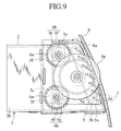
- the operating portion 6p of the operation dial 6d When the wind blown out from the air outlet is to be diffused vertically and blown out as shown in FIG. 5, the operating portion 6p of the operation dial 6d is turned further downward, and the specific mode is selected. With this, the pinion 6c provided on the operation dial 6d rotates the intermediate gear 6a in a counterclockwise direction. Therefore, the pin 5e reaches the bent portion 6g, and the pin 5f reaches the merging portion 6h of the cam groove 6b. This allows the slide link 5 to exceed the normal operating region and is retreated to the specific operating region.
- the fins 3 located at an intermediate position are held in a horizontal position by the guide hole 5a, the fins 3 located above the intermediate position are turned counterclockwise and oriented upward, and the fins 3 located below the intermediate position are turned clockwise and oriented downward.
- the wind blown out from the air outlet is diffused by the fins 3 and blown out toward a passenger.
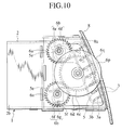
- the operating portion 6p of the operation dial 6d is further turned upward, and the specific mode is selected.
- the pinion 6c provided on the operation dial 6d rotates the intermediate gear 6a further in a clockwise direction. Therefore, the pin 5e reaches the merging portion 6h of the cam groove 6b, and the pin 5f reaches the bent portion 6g of the cam groove 6b. This allows the slide link 5 to exceed the normal operating region and retreat to the specific operating region.
- the fins 3 in the intermediate position are held in a horizontal position by the guide hole 5a of the slide link 5, the fins 3 located above the intermediate position are turned counterclockwise and turned upward, and the fins 3 located below the intermediate position are turned clockwise and turned downward. Therefore, the wind blown out from the air outlet is diffused by the fins 3 and blown out toward a passenger.
- the wind blown out from the air outlet is diffused.
- the direction of the guide hole 5a formed in the slide link 5 is set such that the guide hole 5a located at the intermediate position of the slide link 5 is formed substantially horizontally and the guide hole 5a located above the intermediate position is formed into a substantially U-shape and the guide hole 5a located below the intermediate position is formed into a substantially reversed U-shape and the specific mode is selected, the wind blown out from the air outlet can be collected toward the passenger.
- FIG. 8 to FIG. 17 show modifications. Next, these modifications will be explained.
- the same elements as those in the previous embodiment are designated with the same numerals, and explanation thereof is omitted.
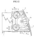
- FIG. 8 to FIG. 13 a shape of the cam groove 6b formed on the intermediate gear 6a is changed.
- the cam groove 6b with which the pin 5e is engaged is formed into a substantially J-shape having the arc portion 6f and a straight portion 6r
- the cam groove 6b with which the pin 5f is engaged is formed by the arc portion 6f and the bent portion 6g.
- the cam grooves 6b with which the pins 5e and 5f are engaged are each formed into substantially J-shapes each having the arc portion 6f, the straight portion 6r, and the merging portion 6h in which front ends of the arc portions 6f are connected to each other.
- the effects of the normal mode and the specific mode are the same as those of the previous embodiment, and thus, explanation thereof is omitted.
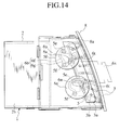
- the mode selector 6 is formed into a push type apparatus.
- an operation knob 6s is used instead of the operation dial 6d.
- the operation knob 6s is supported such that it is movable forward and backward, and guide grooves 6t are formed above and below the operation knob 6s. Pins 6u projected from the intermediate gears 6a are engaged with the guide grooves 6t. If the operation knob 6s is pushed from the specific mode shown in FIG 14, the intermediate gears 6a are rotated in a clockwise direction, and the slide link 5 is moved forward from the specific operating region toward the normal operating region as shown in FIG. 15. With this, the parallel wind blown out from the air outlet is directed into a horizontal direction and can be adjusted downward.
- the operation knob 6s is supported such that it is movable forward and backward, and racks 6v are formed on upper and lower edges of the operation knob 6s. Pinions 6x formed on the intermediate gears 6a are meshed with the racks 6v. If the operation knob 6s is pushed from the specific mode shown in FIG. 16, the intermediate gears 6a are rotated in a clockwise direction and the slide link 5 is moved forward from the specific operating region toward the normal operating region as shown in FIG. 17. Therefore, the parallel wind blown out from the air outlet is turned into a horizontal direction and can be adjusted downward.
- the operation knob 6s is operated in a cross direction in each of the modifications in FIG. 14 to FIG. 17, the normal mode and the specific mode may be selected by operating the operation knob 6s in the vertical direction.
- the fins 3 located above the intermediate position are turned upward, and the fins 3 located below the intermediate position are turned downward.
- the following structure may also be employed. That is, the specific operating region is provided at only one side of the normal operating region so that the fins 3 can be operated to the specific operating region continuously with the normal operating region when the fins 3 are moved upward in the normal operating region, and only the upper direction of the instrument panel may be set as a wind direction adjusting mode.
- the fins 3 may be along the opening 8a of the finisher 8 in the lower direction of the instrument panel, and a lower half of the opening 8a may be fully closed visually.
- a ventilator 11 has a polygonal columnar case 12 whose front face is opened as an opening 12a.
- the case 12 is mounted inside the air outlet which is opened above an instrument panel for example such that the opening 12a is directed rearward of the vehicle (toward a passenger).
- a plurality of fins 13 are horizontally provided at distances from one another in a vertical direction.
- a shaft pin 13a projected from one end of each fin 13 is rotatably pivoted into a notched pin receiver 12c formed on one of side plates 12b of the case 12.
- a shaft pin 13a and a connection pin 13b are projected from the other end of each of the fins 13.
- the shaft pin 13a is rotatably pivoted into a pin receiver 14a of a spacer 14 provided along an opening edge of the other side plate 12b.
- the shaft pins 13a are not pulled out from the receivers 12c and 14a by means of a finisher 18 which abuts against the opening 12a.
- the finisher 18 is formed by a plate which is curved in the vertical direction.
- Retaining pieces 18c projected rearward are provided on opposite sides of the finisher 18. Tip ends of the retaining pieces 18c are engaged with retaining pawls 17a projected from one of outer side surface of the case 12 and outer side surface of the cover 17.
- a spacer 14 is fitted to an opening edge 12d of the case 12.
- Arc long holes 14b curved around pin receivers 14a are formed with respect to a center of the pin receivers 14a.
- a connection pin 13b is projected from the other end of each of the fins 13. The connection pin 13b passes through the long hole 14b and is pivoted into a guide hole 15a of the slide link 15 provided on an outer side surface of the spacer 14.
- the guide holes 15a are formed such that the guide holes 15a located on the intermediate position of the slide link 15 arc formed to be substantially horizontal, the guide holes 15a located above the intermediate position are formed into a substantially reversed U-shape, and the guide holes 15a located below the intermediate position are formed into a substantially U-shape.
- Projecting portions 15b extending rearward are projected from upper and lower portions of the slide link 15.
- Pins 15c are provided at a base end of each of the projecting portion 15b, and Pins 15d are provided at a tip end of each of the projecting portion 15b.
- the pins 15c are engaged with a substantially C-shaped groove 12f formed in the side plate 12b.
- the pins 15d are engaged with substantially falcated cam grooves 16b respectively formed in a pair of intermediate gears 16a constituting a mode selector 16.
- the mode selector 16 selects a normal mode which adjusts a direction of the wind blown out from an air outlet and a specific mode which collects or diffuses the wind blown out from the air outlet.
- the intermediate gear 16a and the operation dial 16d having a pinion 16c which meshes with the intermediate gear 16a are at the same time accommodated in the cover 17 provided in parallel to the other side plate 12a of the case 12 at a distance from each other.
- a shaft hole 16e is formed in a central portion of the operation dial 16d.
- the shaft hole 16e is rotatably supported by a support shaft 12g which projects from an outer side surface of the case 12.
- An operating portion 16f is formed on a front side of the outer peripheral portion of the operation dial 16d.
- the operating portion 16f is projected from the long hole 18b formed in the finisher 18.
- a mark 16g showing an operating position is formed on an outer peripheral surface of the operating portion 16f by a recessed groove and a triangular mark.
- a shaft hole 16i formed in a central portion of the intermediate gear 16a is rotatably supported by the support shaft 12e projected from the outer surface of the case 12.
- a substantially fan-like cam 16h is projected from a rear side of the outer peripheral portion of the operation dial 16d, and an arc cam groove 16j is formed along the outer peripheral surface of the cam 16h.
- a lower end of the cam groove 16j is bent toward a center of the operation dial 16d, and a bent portion 16k is formed.
- a pin 19a projected from a tip end of a shutter opening and closing lever 19 is engaged with the cam groove 16j.
- a polygonal columnar shaft rod 19b is projected from a base end of the shutter opening and closing lever 19 in the opposite direction of the pin 19a.
- the shaft rod 19b is projected into the case 12 from a bearing hole 12h formed in the side plate 12b, and the shaft rod 19b is engaged with a shaft hole 20a of a shutter valve 20 provided in the case 12.
- the shutter valve 20 is formed by a plate having a size capable of rotating in the case 12.
- the shutter valve 20 is rotatably supported by a shaft pin 20b projected from the opposite side of the shaft hole 20a and a side plate 12b of the case 12.
- a sealing member (not shown) which abuts against an inner surface of the case 12 to prevent the wind from leaking when the shutter valve 20 is closed is provided to opposite ends of the shutter valve 2U.
- the mark 16g is set to a substantially central portion of the long hole 18b as shown in FIG. 20, thereby selecting the normal mode.
- the slide link 15 is retreated, and it is moved to a rear end of the normal operating region.
- the pin 15d is located on a connecting portion between the arc portion and the bent portion of the cam groove 16b. Since each of the fins 13 are held horizontally, the direction of the wind blown out from the air outlet is adjusted to the horizontal parallel wind.
- the operating portion 16f of the operation dial 16d When the blowing out direction of the wind is to be adjusted to the upper direction, the operating portion 16f of the operation dial 16d is turned upward. With this, the slide link 15 is moved downward as shown in FIG. 21, and thus, the fins 13 connected to the slide link 15 via the connection pin 13b are turned counterclockwise around the shaft pin 13a. With this, the direction of the wind blown out from the air outlet is adjusted into an upward parallel wind.
- the operating portion 16f is further turned upward to select the specific mode.
- the slide link 15 is moved forward toward a position shown in FIG. 22 by one end of the cam groove 16b.
- the fins 13 at an intermediate position are held horizontally by the guide hole 15a of the slide link 15, the fins 13 located above the intermediate position are turned counterclockwise and turned upward, and the fins 13 located below the intermediate position are turned clockwise and turned downward.
- the wind blown out from the air outlet is diffused by the fins 13 and blown out toward the passenger.
- the operating portion 16f When the wind blown out from the air outlet is to be cut off, the operating portion 16f is further turned downward. With this operation, the slide link 15 is moved to a shutting region, in which an air outlet is closed, in the mode selector 16. The operating portion 16f is further turned downward, so that the pinion 16c rotates the intermediate gear 16a in a counterclockwise direction. Accordingly, the slide link 15 is moved forward to a position shown in FIG. 25 by the other end of the cam groove 16b. Thus, as shown in FIG. 24, all the fins 13 are turned clockwise by the guide hole 15a, and the fins 13 are arranged on a surface along the curved surface of the finisher 18 to close the opening 18a of the finisher 18.
- the pin 19a engaged with the cam 16j is moved toward a center of the operation dial 16d by the bent portion 16k of the cam 16j, thereby turning the shutter opening and closing lever 19 in a counterclockwise direction. Therefore, the shutter valve 20 closes the case 12, thereby substantially completely cutting off the wind blown out from the air outlet. Since the air outlet can be closed by each fins in this manner, an outer appearance of the ventilator when it is not used is enhanced. Further, selection of the specific mode and closing operation of the air outlet can be carried out only by changing the rotating direction by the single mode selector, and thus, operatability of the apparatus is excellent.
- the specific mode is selected by the mode selector 16
- wind blown out from the air outlet is diffused.
- the directions of the guide holes 15a formed in the slide link 15 are formed such that the guide hole 15a located on the intermediate position of the slide link 15 is substantially horizontal and the guide hole 15a located above the intermediate position is formed into a substantially U-shape, and the guide hole 15a located below the intermediate position is formed into a substantially reversed U-shape, the wind blown out from the air outlet can be intensively blown out toward a passenger when the specific mode is selected.
- a direction of the cam groove 16b formed in the intermediate gear 16a may be set to be opposite to the above embodiment.
- the slide link 15 reaches the forward end, and if the operation dial 15d is rotated upward, the slide link 15 is retreated as shown in FIG. 26. With this, the wind blown out from the air outlet is diffused.
- the mode selector can easily be operated from a driver's seat or a passenger's seat and thus, operatability is enhanced. Since the wind blown out from the air outlet can be circulated over the entire compartment, the wind conditioning in the compartment can be carried out excellently.
Landscapes
- Physics & Mathematics (AREA)
- Thermal Sciences (AREA)
- Engineering & Computer Science (AREA)
- Mechanical Engineering (AREA)
- Air-Flow Control Members (AREA)
- Air-Conditioning For Vehicles (AREA)
- Structures Of Non-Positive Displacement Pumps (AREA)
Abstract
Description
Claims (19)
- A ventilator for adjusting a wind direction, comprising:wherein the mode selector has a normal operating region and a specific operating region, anda case;a plurality of fins being operated in a normal mode in which the wind direction is adjusted by turning the fins in parallel to each other, and in a specific mode in which the wind direction is collected or diffused; anda mode selector for continuously selecting the normal mode and the specific mode,
the normal mode is performed in the normal operating region and the specific mode is performed in the specific operating region. - A ventilator according to claim 1,
wherein the specific operating region is provided next to the normal operating region. - A ventilator according to claim 1,
wherein the mode selector comprises an operation dial, an intermediate gear which is rotated by the operation dial, and a slide link which is engaged with a cam groove formed on the intermediate gear and is moved in a cross direction, and
the slide link is moved from the normal operating region to the specific operating region via the intermediate gear such that the normal mode and the specific mode are continuously selected. - A ventilator according to claim 3,
wherein a portion of the operation dial is projected from a front surface of a finisher mounted to an opening of the case. - A ventilator according to claim 3,
wherein a connection pin projected on the fin is engaged with a guide hole formed in the slide link such that the slide link and the fins are interlocked with each other. - A ventilator according to claim 3,
wherein the cam groove comprises a plurality of are portions opposed to each other with respect to a center of the intermediate gear, a bent portion formed by bending one end of the are portions toward the center of the intermediate gear, and a substantialy trapezoidal merging portion formed by merging the other end of the arc portions. - A ventilator according to claim 3,
wherein the cam groove is formed into a substantially J-shape including an arc portion and a straight portion. - A ventilator according to claim 3,
wherein the cam groove comprises a first cam groove which is formed into a substantially J-shape including a first arc portion and a straight portion, and a second cam groove including a second arc portion and a bent portion formed by bending one end of the second arc portion toward a center of the intermediate gear, and
the first cam groove and the second cam groove are opposed to each other with respect to the center of the intermediate gear. - A ventilator according to claim 3,
wherein the cam groove comprises a plurality of grooves which are opposed to each other with respect to a center of the intermediate gear and are formed into a substantially J-shape including an arc portion and a straight portion, and a merging portion formed by merging one end of the grooves. - A ventilator according to claim 1,
wherein the mode selector comprises an operation knob, an intermediate gear rotated by the operation knob, and a slide link which is engaged with a cam groove formed on the intermediate gear and is moved in a cross direction, and
the slide link is moved from the normal operating region to the specific operating region via the intermediate gear such that the normal mode and the specific mode are continuously selected. - A ventilator according to claim 10,
wherein the operation knob includes a guide groove, the intermediate gear has a pin which is inserted into the guide groove, and
an operation force applied to the operation knob is converted into a rotation force of the intermediate gear via the guide groove and the pin. - A ventilator according to claim 10,
wherein the operation knob has a rack, and the intermediate gear has a pinion which is engaged with the rack, and
an operation force applied to the operation knob is converted into a rotation force of the intermediate gear via the rack and the pinion. - A ventilator according to claim 1,
wherein the mode selector has a shutting region in which an air outlet is closed to turn the fins such that an edge of the fin is opposed to an edge of the adjacent fin. - A ventilator according to claim 13,
wherein the mode selector is turned into one direction from the normal mode such that the air outlet is closed, and
the mode selector is turned into the other direction from the normal mode such that the specific mode is selected. - A ventilator according to claim 13,
wherein a shutter valve cooperating with the fins to close in the case when the air outlet is closed by the fins is provided in the case such that the shutter valve is opened and closed. - A ventilator according to claim 15,
wherein the mode selector comprises an operation dial, an intermediate gear which is rotated by the operation dial, and a slide link which is engaged with a cam groove formed on the intermediate gear and is moved in a cross direction,
the operation dial includes an opening and closing cam which is connected to the shutter valve, and
an operation force given to the operation dial is converted into an opening and closing force of the shutter valve via the opening and closing cam. - A ventilator according to claim 16,
wherein the opening and closing cam is set to a fan-like shape, and
an opening and closing cam groove is formed in the opening and closing cam,
an opening and closing pin connected to the shutter valve is engaged to the opening and closing cam groove, so that the shutter valve and the operation dial cooperate with each other. - A ventilator according to claim 1,
wherein the case is disposed on an upper portion of an instrument panel. - A ventilator (1; 11) comprising baffle means for controlling flow of air through an aperture, the baffle means comprising a plurality of baffle plates (3; 13) and pivoting means (5, 6; 15, 16) for pivoting said baffle plates, wherein the baffle means is operable in a first mode in which the baffle plates are pivotable to retain a substantially parallel relationship one to another for directing the flow of air, and in a second mode in which the baffle plates are pivotable to cause divergence or convergence of the flow of air; and wherein an actuator (6d; 16d) is provided for controlling actuation of said baffle means from one of said first and said second modes to another of said first and said second modes and for controlling pivotal movement of said baffle plates in said first mode and in said second mode.
Applications Claiming Priority (4)
| Application Number | Priority Date | Filing Date | Title |
|---|---|---|---|
| JP2001272226A JP4744038B2 (en) | 2001-09-07 | 2001-09-07 | Wind direction adjustment device |
| JP2001272226 | 2001-09-07 | ||
| JP2001294436 | 2001-09-26 | ||
| JP2001294436A JP4721590B2 (en) | 2001-09-26 | 2001-09-26 | Wind direction adjustment device |
Publications (3)
| Publication Number | Publication Date |
|---|---|
| EP1291209A2 true EP1291209A2 (en) | 2003-03-12 |
| EP1291209A3 EP1291209A3 (en) | 2004-04-14 |
| EP1291209B1 EP1291209B1 (en) | 2005-11-09 |
Family
ID=26621847
Family Applications (1)
| Application Number | Title | Priority Date | Filing Date |
|---|---|---|---|
| EP02256195A Expired - Lifetime EP1291209B1 (en) | 2001-09-07 | 2002-09-06 | Ventilator |
Country Status (3)
| Country | Link |
|---|---|
| US (1) | US6652371B2 (en) |
| EP (1) | EP1291209B1 (en) |
| DE (1) | DE60207168T2 (en) |
Cited By (6)
| Publication number | Priority date | Publication date | Assignee | Title |
|---|---|---|---|---|
| FR2864807A1 (en) * | 2004-01-07 | 2005-07-08 | Faurecia Interieur Ind | Ventilator for use in dashboard of motor vehicle, has transmission assembly displacing rotary operating device to vary relative inclination of fins, during diffuser mode, so that air flow is diffused in three directions |
| EP1752324A1 (en) * | 2005-08-10 | 2007-02-14 | Dr. Schneider Kunststoffwerke GmbH | Air nozzle |
| FR2901739A1 (en) | 2006-06-01 | 2007-12-07 | Coutier Moulage Gen Ind | Ventilator for diffusing air into cab interior of motor vehicle, has displacing unit orienting fins to be highly divergent with respect to each other and central fin to obtain soft diffusion mode |
| EP1867507A1 (en) * | 2006-06-15 | 2007-12-19 | Ford Global Technologies, LLC | Air vent outlet nozzle |
| EP1911616A1 (en) * | 2006-10-12 | 2008-04-16 | fischer automotive systems GmbH | Air jet for ventilating the inside of a vehicle |
| CN106687315A (en) * | 2014-09-24 | 2017-05-17 | 利富高(韩国)股份有限公司 | Air vent for vehicle |
Families Citing this family (33)
| Publication number | Priority date | Publication date | Assignee | Title |
|---|---|---|---|---|
| US6780098B2 (en) * | 2002-02-15 | 2004-08-24 | Nifco Inc. | Regulator for air outlet |
| GB2390891B (en) * | 2002-06-28 | 2006-05-10 | Nihon Plast Co Ltd | Ventilator |
| US6830511B2 (en) * | 2003-01-21 | 2004-12-14 | Collins & Aikman Products Co. | Air duct outlets with remotely-located joystick louver controls |
| GB0304791D0 (en) * | 2003-03-03 | 2003-04-09 | Ford Global Tech Llc | Air vent for vehicle air ducting |
| JP4259224B2 (en) * | 2003-08-06 | 2009-04-30 | 豊田合成株式会社 | Air conditioning register |
| US6974377B2 (en) * | 2004-02-05 | 2005-12-13 | Collins & Aikman Products Co. | Air duct outlets for inclined surfaces |
| JP4379188B2 (en) * | 2004-04-22 | 2009-12-09 | 豊田合成株式会社 | Air conditioning register |
| KR100613711B1 (en) * | 2004-09-15 | 2006-08-21 | 현대모비스 주식회사 | Air vent of vehicle |
| US6932695B1 (en) * | 2004-10-28 | 2005-08-23 | Daimlerchrysler Corporation | Vane for an air outlet |
| DE502005002658D1 (en) * | 2005-05-03 | 2008-03-13 | Behr France Rouffach Sas | Actuating device for at least three flaps of a ventilation, heating or air conditioning system of a motor vehicle |
| JP4678526B2 (en) * | 2005-09-14 | 2011-04-27 | 豊田合成株式会社 | Air conditioning register |
| EP2046591A4 (en) * | 2006-07-27 | 2010-04-21 | Collins & Aikman Prod Co | Air vent providing diffusion |
| KR101479369B1 (en) * | 2007-09-21 | 2015-01-05 | 에어그린 엘티디. | Equipment of dispersing air jets from air conditioning systems and mixing them with ambient air |
| US8113229B2 (en) * | 2008-07-24 | 2012-02-14 | Honda Motor Co., Ltd. | Gear operated shut valve for a ventilation system |
| US8403734B2 (en) * | 2009-02-20 | 2013-03-26 | Deere & Company | Vent control system |
| JP4856754B2 (en) * | 2009-12-25 | 2012-01-18 | 本田技研工業株式会社 | Air conditioning structure for vehicle air conditioning |
| KR101305822B1 (en) * | 2011-10-17 | 2013-09-06 | 현대자동차주식회사 | Air conditioning system for vehicle |
| KR101542853B1 (en) * | 2013-04-23 | 2015-08-07 | 현대모비스 주식회사 | The Airbent of Vehicle |
| DE102013111175B3 (en) * | 2013-10-09 | 2014-09-04 | Dr. Schneider Kunststoffwerke Gmbh | Air outlet for air conditioning apparatus, has lying chambers for first terminal and second terminal, which are opened for supplying or discharging air for generating overpressure and low pressure respectively |
| JP6160580B2 (en) * | 2014-08-08 | 2017-07-12 | トヨタ自動車株式会社 | Resistor fixing structure for vehicle |
| SE538880C2 (en) * | 2014-11-10 | 2017-01-24 | China-Euro Vehicle Tech Ab | Air nozzle device for a vehicle |
| KR101704916B1 (en) * | 2015-08-18 | 2017-02-08 | 주식회사 니프코코리아 | Dual Damper Device of Air Vent for Automobiles |
| CN107672419B (en) * | 2016-08-02 | 2022-08-12 | 福特环球技术公司 | Air outlet assembly and method for assembling air outlet system |
| US10752088B2 (en) * | 2016-12-09 | 2020-08-25 | Tesla, Inc. | Infotainment system with air-vent control |
| KR102429172B1 (en) * | 2016-12-21 | 2022-08-03 | 현대자동차주식회사 | Device for adjusting air flow direction of slim type air vent for vehicle |
| KR102394798B1 (en) * | 2017-09-25 | 2022-05-04 | 현대자동차주식회사 | Device for opening and closing damper using knob ofr air vent |
| KR102598528B1 (en) * | 2018-05-16 | 2023-11-03 | 현대자동차주식회사 | Motor driven air vent device for vehicle |
| DE102019100496B4 (en) * | 2019-01-10 | 2022-03-03 | Dr. Schneider Kunststoffwerke Gmbh | Bearing arrangement and air vent with a bearing arrangement |
| US11660930B2 (en) * | 2019-10-14 | 2023-05-30 | Denso International America, Inc. | Actuator assembly |
| US11738624B2 (en) | 2020-08-12 | 2023-08-29 | Ford Global Technologies, Llc | Air register assembly |
| KR20220114995A (en) | 2021-02-09 | 2022-08-17 | 현대모비스 주식회사 | Air vent apparatus of vehicle with direct and indirect mullti function |
| US20240190218A1 (en) * | 2022-12-13 | 2024-06-13 | Global Ip Holdings, Llc | Vent Register Having Movable Set of Differently Oriented Vanes to Reduce Air Blow Fanning |
| DE102023103899B4 (en) * | 2023-02-16 | 2025-01-09 | Weber Gmbh & Co. Kg Kunststofftechnik Und Formenbau | air outlet with adjustable air outlet direction |
Family Cites Families (16)
| Publication number | Priority date | Publication date | Assignee | Title |
|---|---|---|---|---|
| US2901961A (en) * | 1956-09-04 | 1959-09-01 | Louis C Cotts | Floor register with adjustable louvers |
| JPS6179145U (en) * | 1984-10-29 | 1986-05-27 | ||
| US4653386A (en) * | 1984-11-20 | 1987-03-31 | Toyota Jidosha Kabushiki Kaisha | Wind direction adjusting mechanism for air conditioner |
| DE3529463A1 (en) * | 1985-08-16 | 1987-02-26 | Opel Adam Ag | OUTLET NOZZLE ON VENTILATION OR AIR CONDITIONING |
| DE3628449A1 (en) * | 1986-08-21 | 1988-02-25 | Happich Gmbh Gebr | AIR DUCTING DEVICE |
| EP0417351B1 (en) * | 1989-09-12 | 1992-06-17 | Siemens Aktiengesellschaft | Discharge nozzle for ventilating or air conditioning installations |
| US5080002A (en) * | 1989-09-12 | 1992-01-14 | Siemens Aktiengesellschaft | Outlet nozzle for ventilation or air-conditioning systems |
| ES2034557T3 (en) * | 1989-10-24 | 1993-04-01 | Siemens Aktiengesellschaft | OUTLET NOZZLE FOR VENTILATION OR AIR CONDITIONING FACILITIES. |
| JP2840382B2 (en) | 1990-05-30 | 1998-12-24 | 日本プラスト株式会社 | Wind direction adjustment device |
| KR100230108B1 (en) * | 1991-12-30 | 1999-11-15 | 구자홍 | How to Play a Message on an Answering Machine |
| WO1994000310A1 (en) * | 1992-06-19 | 1994-01-06 | Dr. Franz Schneider Gmbh | Nozzle for ventilating or air conditioning installations, especially in motor vehicle interiors |
| US5338252A (en) * | 1993-05-06 | 1994-08-16 | Manchester Plastics, Ltd. | Air outlet louver assembly |
| US5470276A (en) * | 1993-09-21 | 1995-11-28 | Aeroquip Corporation | Diffuser air outlet |
| FR2766765B1 (en) * | 1997-08-04 | 1999-10-01 | Coutier Moulage Gen Ind | AERATOR BARREL FOR A MOTOR VEHICLE |
| US6129627A (en) * | 1998-10-21 | 2000-10-10 | Collins & Aikman Plastics, Inc. | Air outlet assembly having outer air directing doors |
| KR20020021720A (en) * | 2000-09-16 | 2002-03-22 | 이계안 | Air ventilator for automobile |
-
2002
- 2002-09-06 DE DE60207168T patent/DE60207168T2/en not_active Expired - Fee Related
- 2002-09-06 EP EP02256195A patent/EP1291209B1/en not_active Expired - Lifetime
- 2002-09-09 US US10/238,300 patent/US6652371B2/en not_active Expired - Fee Related
Cited By (8)
| Publication number | Priority date | Publication date | Assignee | Title |
|---|---|---|---|---|
| FR2864807A1 (en) * | 2004-01-07 | 2005-07-08 | Faurecia Interieur Ind | Ventilator for use in dashboard of motor vehicle, has transmission assembly displacing rotary operating device to vary relative inclination of fins, during diffuser mode, so that air flow is diffused in three directions |
| WO2005068234A1 (en) * | 2004-01-07 | 2005-07-28 | Faurecia Interieur Industrie | Adjustable ventilator for a motor vehicle cabin and an internal equipment element of a vehicle provided with said ventilator |
| EP1752324A1 (en) * | 2005-08-10 | 2007-02-14 | Dr. Schneider Kunststoffwerke GmbH | Air nozzle |
| FR2901739A1 (en) | 2006-06-01 | 2007-12-07 | Coutier Moulage Gen Ind | Ventilator for diffusing air into cab interior of motor vehicle, has displacing unit orienting fins to be highly divergent with respect to each other and central fin to obtain soft diffusion mode |
| EP1867507A1 (en) * | 2006-06-15 | 2007-12-19 | Ford Global Technologies, LLC | Air vent outlet nozzle |
| EP1911616A1 (en) * | 2006-10-12 | 2008-04-16 | fischer automotive systems GmbH | Air jet for ventilating the inside of a vehicle |
| CN106687315A (en) * | 2014-09-24 | 2017-05-17 | 利富高(韩国)股份有限公司 | Air vent for vehicle |
| CN106687315B (en) * | 2014-09-24 | 2018-12-18 | 利富高(韩国)股份有限公司 | Air vent of automobile |
Also Published As
| Publication number | Publication date |
|---|---|
| US20030050001A1 (en) | 2003-03-13 |
| DE60207168T2 (en) | 2006-08-10 |
| EP1291209B1 (en) | 2005-11-09 |
| DE60207168D1 (en) | 2005-12-15 |
| US6652371B2 (en) | 2003-11-25 |
| EP1291209A3 (en) | 2004-04-14 |
Similar Documents
| Publication | Publication Date | Title |
|---|---|---|
| EP1291209A2 (en) | Ventilator | |
| US9724981B2 (en) | Air conditioning register | |
| JP6536395B2 (en) | Air conditioning register | |
| WO2007136076A1 (en) | Air outlet structure for air conditioner | |
| JP3572480B2 (en) | Wind direction adjustment mechanism of automotive register | |
| JP6239858B2 (en) | register | |
| JP5724852B2 (en) | Air conditioning register | |
| JP5529564B2 (en) | register | |
| JP2022181529A (en) | Wind direction adjustment device | |
| JP2013112256A (en) | Register for air conditioning | |
| JP2008001344A (en) | Air conditioner outlet structure | |
| JP4118198B2 (en) | register | |
| JP4721590B2 (en) | Wind direction adjustment device | |
| JP3829691B2 (en) | Wind direction adjustment device | |
| JP3362124B2 (en) | register | |
| JP4744038B2 (en) | Wind direction adjustment device | |
| JP2005009751A (en) | Register | |
| JP2018065471A (en) | register | |
| JP5028349B2 (en) | register | |
| JP2840382B2 (en) | Wind direction adjustment device | |
| JP5873697B2 (en) | Air conditioning control device | |
| JP2015033905A (en) | Register | |
| JP3829700B2 (en) | Wind direction adjustment device | |
| JP3486727B2 (en) | Automotive registers | |
| JP3507950B2 (en) | Vehicle wind direction adjusting device |
Legal Events
| Date | Code | Title | Description |
|---|---|---|---|
| PUAI | Public reference made under article 153(3) epc to a published international application that has entered the european phase |
Free format text: ORIGINAL CODE: 0009012 |
|
| AK | Designated contracting states |
Kind code of ref document: A2 Designated state(s): AT BE BG CH CY CZ DE DK EE ES FI FR GB GR IE IT LI LU MC NL PT SE SK TR |
|
| AX | Request for extension of the european patent |
Extension state: AL LT LV MK RO SI |
|
| PUAL | Search report despatched |
Free format text: ORIGINAL CODE: 0009013 |
|
| AK | Designated contracting states |
Kind code of ref document: A3 Designated state(s): AT BE BG CH CY CZ DE DK EE ES FI FR GB GR IE IT LI LU MC NL PT SE SK TR |
|
| AX | Request for extension of the european patent |
Extension state: AL LT LV MK RO SI |
|
| RIC1 | Information provided on ipc code assigned before grant |
Ipc: 7B 60H 1/00 B Ipc: 7B 60H 1/34 A |
|
| 17P | Request for examination filed |
Effective date: 20040616 |
|
| 17Q | First examination report despatched |
Effective date: 20040723 |
|
| AKX | Designation fees paid |
Designated state(s): DE GB |
|
| GRAP | Despatch of communication of intention to grant a patent |
Free format text: ORIGINAL CODE: EPIDOSNIGR1 |
|
| GRAS | Grant fee paid |
Free format text: ORIGINAL CODE: EPIDOSNIGR3 |
|
| GRAA | (expected) grant |
Free format text: ORIGINAL CODE: 0009210 |
|
| AK | Designated contracting states |
Kind code of ref document: B1 Designated state(s): DE GB |
|
| REG | Reference to a national code |
Ref country code: GB Ref legal event code: FG4D |
|
| REF | Corresponds to: |
Ref document number: 60207168 Country of ref document: DE Date of ref document: 20051215 Kind code of ref document: P |
|
| PLBE | No opposition filed within time limit |
Free format text: ORIGINAL CODE: 0009261 |
|
| STAA | Information on the status of an ep patent application or granted ep patent |
Free format text: STATUS: NO OPPOSITION FILED WITHIN TIME LIMIT |
|
| 26N | No opposition filed |
Effective date: 20060810 |
|
| PGFP | Annual fee paid to national office [announced via postgrant information from national office to epo] |
Ref country code: DE Payment date: 20080919 Year of fee payment: 7 |
|
| PG25 | Lapsed in a contracting state [announced via postgrant information from national office to epo] |
Ref country code: DE Free format text: LAPSE BECAUSE OF NON-PAYMENT OF DUE FEES Effective date: 20100401 |
|
| PGFP | Annual fee paid to national office [announced via postgrant information from national office to epo] |
Ref country code: GB Payment date: 20100901 Year of fee payment: 9 |
|
| GBPC | Gb: european patent ceased through non-payment of renewal fee |
Effective date: 20110906 |
|
| PG25 | Lapsed in a contracting state [announced via postgrant information from national office to epo] |
Ref country code: GB Free format text: LAPSE BECAUSE OF NON-PAYMENT OF DUE FEES Effective date: 20110906 |