JP5529564B2 - register - Google Patents
register Download PDFInfo
- Publication number
- JP5529564B2 JP5529564B2 JP2010018912A JP2010018912A JP5529564B2 JP 5529564 B2 JP5529564 B2 JP 5529564B2 JP 2010018912 A JP2010018912 A JP 2010018912A JP 2010018912 A JP2010018912 A JP 2010018912A JP 5529564 B2 JP5529564 B2 JP 5529564B2
- Authority
- JP
- Japan
- Prior art keywords
- knob
- barrel
- register
- air outlet
- front plate
- Prior art date
- Legal status (The legal status is an assumption and is not a legal conclusion. Google has not performed a legal analysis and makes no representation as to the accuracy of the status listed.)
- Expired - Fee Related
Links
Images


Landscapes
- Air-Conditioning For Vehicles (AREA)
Description
本発明は、自動車等の空調の吹出口に使用される空気吹出調整用のレジスタに関し、特に空気吹出口の前面を視覚的に非透視性とした構造のレジスタに関する。 The present invention relates to an air blowing adjustment register used for an air-conditioning outlet of an automobile or the like, and more particularly to a register having a structure in which the front surface of an air outlet is visually non-transparent.
空気吹出調整用のレジスタとして、通風路を形成するベゼルまたはリテーナ内に、横可動ルーバと縦可動ルーバを前後して配設し、ベゼルに設けた空気吹出口から空気を吹き出す際、横可動ルーバ、縦可動ルーバの各フィンの角度を変えて空気の吹出し方向を調整するレジスタが、自動車の空調装置の吹出口としてインストルメントパネルなどに設けられている。 As a register for adjusting the air blowing, a laterally movable louver and a longitudinally movable louver are arranged in front and back in a bezel or retainer that forms a ventilation path, and when the air is blown from an air outlet provided in the bezel, the laterally movable louver A register that adjusts the air blowing direction by changing the angle of each fin of the longitudinally movable louver is provided on an instrument panel or the like as an air outlet of an automobile air conditioner.
近年、自動車室内におけるインストルメントパネル近傍のインテリアデザインは、全体的に統一感のある、シンプルでモデュール化されたイメージをコンセプトとする傾向にあり、このために、空気吹出口の前面を視覚的に非透視性とする空調用レジスタが、下記特許文献1などで提案されている。
In recent years, interior design in the vicinity of instrument panels in automobile interiors has a tendency to be based on the concept of a simple, modularized image with a sense of unity overall. A non-transparent air-conditioning register is proposed in
このレジスタは、空気吹出口の前面を格子により覆い、格子によって、内部に配設した風向調整のための干渉部材などの内部機構を視覚的に見えにくい非透視性の構造とし、このために、略長方形の環状リムの内側に多数の多角形孔を配置した構造の格子を、レジスタの空気吹出口の前面全体を覆うように被せて取り付けている。
しかし、この従来のレジスタは、格子によりレジスタの風向調整機構などを視覚的に見えにくくしているものの、周縁部に環状リムを設けた格子を、空気吹出口全体を覆って嵌着しているため、格子による送風時の圧力損失が大きく、また、操作ノブにより内部の風向調整機構を動かして風向を調整した場合、格子により風の風速感やスポット感が著しく低下する課題があった。 However, although this conventional register makes the wind direction adjustment mechanism of the register difficult to see visually by the lattice, a lattice having an annular rim at the peripheral edge is fitted over the entire air outlet. Therefore, the pressure loss at the time of the ventilation by a grating | lattice is large, and when the wind direction was adjusted by moving an internal wind direction adjustment mechanism with an operation knob, there existed a subject to which the wind speed feeling and spot feeling of a wind fell remarkably by a grating | lattice.
さらに、このレジスタの風向調整機構は、矩形フレーム状の干渉部材を、操作ノブにより左右または上下に傾動させて、風向を変える構造のため、矩形フレーム状の干渉部材を傾動させただけでは、風向を適正に変えることができず、これによっても、送風時の風速感やスポット感が損なわれていた。 Furthermore, the wind direction adjusting mechanism of this register is structured to change the wind direction by tilting the rectangular frame-shaped interference member left and right or up and down with the operation knob, so that the wind direction can be obtained only by tilting the rectangular frame-shaped interference member. As a result, the wind speed feeling and the spot feeling at the time of blowing were impaired.
一方、車内のインテリアデザインの全体的な統一性のため、或いはレジスタの空気吹出口の前面を視覚的に非透視性とするために、空気吹出口の形状を縦または横に細長いスリット状とすることが行われているが、上記従来のレジスタにおいて、空気吹出口の形状を長手方向に細長いスリット状にした場合、矩形フレーム状の干渉部材を傾動させて、吹出口の短手方向に風向を調整したとしても、干渉部材の風向調整機能が低く、風向調整時の風速感やスポット感を悪いという課題があった。 On the other hand, in order to make the interior design of the interior of the vehicle uniform, or to make the front of the air outlet of the register visually non-transparent, the shape of the air outlet is formed into a slit shape that is elongated vertically or horizontally. However, in the conventional register described above, when the shape of the air outlet is a long and narrow slit in the longitudinal direction, the rectangular frame-shaped interference member is tilted so that the air direction is changed in the short direction of the outlet. Even if the adjustment is made, the wind direction adjustment function of the interference member is low, and there is a problem that the wind speed feeling and the spot feeling at the time of wind direction adjustment are poor.
本発明は、上記の点に鑑みてなされたもので、空気吹出口の前面を視覚的に非透視性とすると共に、風向調整時の風速感やスポット感を向上させることができるレジスタを提供することを目的とする。 The present invention has been made in view of the above points, and provides a register capable of visually making the front surface of an air outlet visually non-transparent and improving a wind speed feeling and a spot feeling at the time of wind direction adjustment. For the purpose.
上記目的を達成するために、本発明のレジスタは、
長手方向に長く短手方向に短い細長の空気吹出口を有し、該空気吹出口の内側にバレルが該長手方向の軸の回りで回動可能に軸支されたレジスタにおいて、
該バレル内に可動ルーバが、複数のフィンを該バレルの回動軸と直交する軸の回りで回動可能に軸支して設けられ、
操作ノブが、該バレルを該回動軸の回りで回動させ、且つ該可動ルーバの各フィンを該軸の回りで回動させて風向を調整するように設けられ、
レジスタの前面がレジスタの前部を形成するベゼルの正面板により一体形成され、
該正面板は縦長に形成されるとともに、上下長手方向に湾曲して形成され、
該正面板の中央部に前記空気吹出口が縦長の長方形状に形成され、
該空気吹出口の正面を略覆うように格子部が設けられ、
該格子部の両側にスリット開口部が該空気吹出口の長手方向に向けて設けられたことを特徴とする。
In order to achieve the above object, the register of the present invention provides:
In a register having an elongated air outlet that is long in the longitudinal direction and short in the lateral direction, and a barrel pivotally supported around the longitudinal axis inside the air outlet,
A movable louver is provided in the barrel such that a plurality of fins are pivotally supported around an axis orthogonal to the rotation axis of the barrel.
An operation knob is provided to rotate the barrel about the rotation axis and adjust the wind direction by rotating the fins of the movable louver about the axis;
The front surface of the register is integrally formed by the front plate of the bezel that forms the front of the register,
The front plate is formed in a vertically long shape and is curved in the vertical direction.
The air outlet is formed in a vertically long rectangular shape at the center of the front plate,
A lattice portion is provided so as to substantially cover the front of the air outlet,
A slit opening is provided on both sides of the lattice portion in the longitudinal direction of the air outlet.
この発明のレジスタによれば、ベゼルの正面板が縦長に形成されるとともに、上下長手方向に湾曲して形成され、正面板の中央部に空気吹出口が縦長の長方形状に形成され、空気吹出口の正面を略覆うように格子部が設けられ、内部を隠蔽するので、レジスタ内を視覚的に非透視状態とし、レジスタの意匠性を改善することができる。また、格子部の両側にスリット開口部が空気吹出口の長手方向に向けて設けられるので、バレルを回動させて風向を左右に振ったとき、格子部の右側または左側のスリット開口部から風抜けの良好な送風を行なって、風向調整時の風速感やスポット感を向上させることができる。
また、レジスタの前面が、ベゼルの正面板により一体成形され、その正面板の空気吹出口を覆うように格子部が設けられるので、レジスタ前面におけるデザインの統一感を図ることができる。
According to the register of the present invention, the front plate of the bezel is formed vertically and curved in the vertical direction, and the air outlet is formed in a vertically long rectangular shape at the center of the front plate. Since the lattice portion is provided so as to substantially cover the front face of the outlet and the inside is concealed, the inside of the register can be visually made non-transparent and the design of the register can be improved . Further, since the slit opening on both sides of the grating portion is provided towards the longitudinal direction of the air outlet, when swung to the right and left wind direction by rotating the barrel, the wind from the right or left side of the slit opening of the grating portion It is possible to improve the wind speed feeling and the spot feeling at the time of adjusting the wind direction by blowing air with a good escape .
In addition, since the front surface of the register is integrally formed with the front plate of the bezel and the lattice portion is provided so as to cover the air outlet of the front plate, it is possible to achieve a unified design on the front surface of the register.
ここで、上記レジスタにおいて、上記正面板の縁部にノブ用開口部が設けられ、該ノブ用開口部に前記操作ノブを配設することが好ましい。 Here, in the register, the knob opening is provided in the edge of the front plate, it is preferable to provide the operation knob to the opening for the knob.
また、上記レジスタにおいて、前記操作ノブは、前記ベゼルの正面板の下側に水平に支持されたノブ軸上に、ノブ本体を摺動可能に軸支して構成され、該ノブ本体にはノブ保持部が該ノブ本体と共に移動可能に設けられ、該ノブ本体の軸方向の動きを、該ノブ保持部を介して前記バレルの回動軸に伝達して回動させるバレルリンク機構が設けられ、該ノブ本体の回動を前記可動ルーバの各フィンに伝達して傾動させる可動ルーバリンク機構を設けることが好ましい。 Further, in the register, the operation knob is configured such that a knob body is slidably supported on a knob shaft horizontally supported on a lower side of the front plate of the bezel, and the knob body includes a knob. A holding portion is provided so as to be movable together with the knob body, and a barrel link mechanism is provided that transmits the movement of the knob body in the axial direction to the turning shaft of the barrel via the knob holding portion, and rotates. It is preferable to provide a movable louver link mechanism that transmits the rotation of the knob body to each fin of the movable louver to tilt the knob body.
この発明によれば、簡単な機構と1個のノブ本体の操作により、バレルの向きの角度調整、及び可動ルーバのフィンの角度調整を行って、風向を上下左右に簡便に変えることができる。 According to the present invention, the angle of the barrel direction and the angle of the fins of the movable louver can be adjusted by a simple mechanism and operation of one knob body, and the wind direction can be easily changed vertically and horizontally.
本発明のレジスタによれば、空気吹出口の前面を視覚的に非透視性とし、風向調整時の風速感やスポット感を向上させることができる。 According to the register of the present invention, the front surface of the air outlet can be made visually non-transparent to improve the feeling of wind speed and the feeling of spot when adjusting the wind direction.
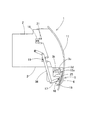
以下、本発明の実施の形態を図面に基づいて説明する。図1〜図7に示すように、本実施形態のレジスタは、ベゼル1に形成された空気吹出口10の前面が、格子部13により略覆われることにより、その内部を視覚的に非透視性とした構造となっている。ベゼル1の正面板11は、略長方形の板を上下に湾曲して形成され、そこには縦長の長方形状に空気吹出口10が形成される。空気吹出口10は、中央部に格子部13が吹出口を覆うように形成され、格子部13の両側には、縦に長いスリット開口部12が空気吹出口10の長手方向(縦方向)に沿って形成される。
Hereinafter, embodiments of the present invention will be described with reference to the drawings. As shown in FIGS. 1 to 7, the register of the present embodiment is such that the front surface of the
つまり、空気吹出口10は、中央部を覆う格子部13と、その格子部13の両側に配置されるスリット開口部12、12とから構成され、格子部13は、正面板11の上下の縁部から延設されるように一体成形される。格子部13の格子は多数の六角孔を縦横に配列して形成され、格子部13は正面板11と同様に上下方向に湾曲して形成されている。なお、格子部13はここでは多数の六角孔を縦横に配置してハニカム状に形成されるが、六角孔のほか、多数の円形孔や方形孔を縦横に配置して形成することもできる。
That is, the
図1に示す実施形態では、格子部13とスリット開口部12,12との幅比、つまり図1のa:b:aの比は、7:30:7となっており、空気吹出口10の幅を100(%)としたときの格子部13の幅の割合、及びスリット開口部12の幅の割合は、16(%):68(%):16(%)に形成されている。
In the embodiment shown in FIG. 1, the width ratio between the
格子部13の幅bとスリット開口部12の幅aの関係は、格子部13の幅が狭くスリット開口部12の幅が広くなるほど、レジスタの内部が視覚的に見え易くなり、デザイン性が低下する一方、風の向きを左右に振ったときの風の抜けが改善され、逆に、格子部13の幅が広くスリット開口部12の幅が狭くなるほど、レジスタの内部が視覚的に見えにくくなって、デザイン性が向上する一方、風の向きを左右に振ったときの風の抜けは悪化する。
The relationship between the width b of the
この点を考慮して、レジスタの内部を視覚的に見えにくくして、意匠性を改善し、且つ風の向きを左右に振ったときの風の抜けを良くするためには、格子部13とスリット開口部12,12との幅比は、10(%):80(%):10(%)から22(%):56(%):22(%)の範囲とすることが効果的であり、望ましくは、13(%):74(%):13(%)から19(%):62(%):19(%)の範囲とすることが好ましい。
In consideration of this point, in order to make the inside of the register difficult to see visually, to improve the design, and to improve the draft of the wind when the direction of the wind is swung to the left and right, The width ratio between the
このような格子部13とスリット開口部12、12を空気吹出口10に形成した、正面板11を有するベゼル1は、例えばABS樹脂などにより一体成形される。ベゼル1の成形時に格子部13が一体成形されることにより、別体の格子部材を空気吹出口に嵌め込む場合に比べ、部品点数の削減や組付工数の削減を図ることができる。
The
正面板11の下部には、図1に示す如く、ノブ用開口部14が形成され、そこから前方に露出(突出)するように、操作ノブ5のノブ本体6が配設される。操作ノブ5の左右への摺動操作により、バレル3の左右の向きを調整し、操作ノブ5の回動操作により、可動ルーバ4の横フィン31を上下に調整する構造となっている。
As shown in FIG. 1, a
ベゼル1の内側(背面側)にはリテーナ2に連結するための方形の嵌合部が設けられ、その嵌合部の両側に、図3のように、2対の係止部18が後方に向けて突設される。一方、ベゼル1の後部にはダクト状のリテーナ2が、その側壁に設けた2対の係止受部21に係止部18を嵌合して接続される。
A rectangular fitting portion for connecting to the
リテーナ2は、図3に示す如く、略方形のダクト状に形成され、内部に通風路9が形成され、前後に開口している。リテーナ2の前縁部の上部と下部には、バレル3の上下の回動軸3a、3bを軸支する軸受部22、23が形成され、これらの軸受部22、23の間にバレル3を挿入し、上下の回動軸3a、3bを軸受部22、23に回動可能に嵌合させて支持するようになっている。また、軸受部22、23には係止爪または係止凹部が設けられ、リテーナ2の前部にベゼル1を嵌合させたとき、軸受部22,23がベゼル1の後部に嵌着される構造となっている。このように、リテーナ2の前部には、正面に空気吹出口10を開口形成したベゼル1が、その空気吹出口10を通風路9の開口部に合わせるように嵌着される。
As shown in FIG. 3, the
バレル3は、図3に示す如く、内側に縦長の開口空間を有し、前後に開口して形成され、リテーナ2の前部に装着されて、その上下の回動軸3a、3bを軸に、左右に回動することにより、空気吹出口10から送風される風の向きを、左方向または右方向に変えるように構成される。バレル3の下部の回動軸3bにはクランク3cが連結され、クランク3cの偏倚軸3dが、操作ノブ5のノブ本体6におけるノブ保持部15の二股係合部15aに係合する。
As shown in FIG. 3, the
ノブ保持部15にはノブ本体6を前方に露出または突出させる開口部15bが形成され、ノブ保持部15の内側には、ノブ本体6を支持するノブ軸16を保持する軸受部15cが設けられ、軸受部15cにノブ軸16を保持させた状態で、ノブ本体6はその一部を開口部15bから露出させるように取り付けられる。これにより、操作ノブ5のノブ本体6をノブ軸16上で右又は左に移動操作すると、ノブ保持部15の二股係合部15aが同様に右又は左に移動し、クランク3cが偏倚軸3dを介して回動力を受けて、下部の回動軸3bが回動し、これに伴い、バレル3がその上下の回動軸3a、3bを軸に左右に回動する。
The
操作ノブ5のノブ本体6は、図2,3に示すように、リテーナ2の下部に設けたノブ軸受部25,25により、水平に支持されたノブ軸16上に、軸方向に摺動可能に取り付けられる。ノブ軸16はその断面を円形以外の異形断面の軸として形成され、ノブ本体6の軸芯位置にその異形断面に対応した形状の異形孔が形成され、ノブ軸16上でノブ本体6が軸方向に摺動可能で、且つノブ本体6の回動時にはその回動力をノブ軸16に伝達可能としている。なお、ノブ本体6の異形孔には、ゴム状弾性体などの操作荷重付与材6aが嵌着され、ノブ本体6をノブ軸16上で摺動させた際に適度な操作荷重を付与するようにしている。
As shown in FIGS. 2 and 3, the
ノブ軸16はリテーナ2の下部に設けたノブ軸受部25,25に回動可能に支持されるが、ノブ軸16の端部にはクランク17が設けられ、そのクランク17はリンク38を介して可動ルーバ4の横フィン31を回動させるフィン回動軸35に連係される。
The
可動ルーバ4は、バレル3内に例えば4枚の横フィン31を水平状態で縦に並設して構成され、各横フィン31は、図3,4に示すように、バレル3内でその両側のフィン軸32をバレル側壁に設けた軸孔に挿入し、バレル3内で上下に回動可能に支持される。図4,5に示すように、各横フィン31の後部両側におけるフィン軸32から偏倚した位置に、偏倚軸31aが両側に突設され、それら両側の偏倚軸31aを連結して1対のリンクバー33,33が取り付けられ、1対のリンクバー33,33は円弧状リンク34により連結されている。
The
一方、可動ルーバ4の横フィン31を回動させるフィン回動軸35は、図3,5に示すように、リテーナ2の側壁に設けた水平軸受部24,24に水平に軸支される。フィン回動軸35の中間部には二股係合部36が設けられ、上記横フィン31に連結される円弧状リンク34がその二股係合部36に係合する。これにより、フィン回動軸35が回動すると、二股係合部36が上下に回動し、円弧状リンク34を介して1対のリンクバー33が上下動し、このリンクバー33の上下動により、可動ルーバ4の4枚の横フィン31はそのフィン軸32を軸に上下に回動する。
On the other hand, the
フィン回動軸35は、クランク37を介してリンク38に連結し、リンク38はクランク17を介してノブ軸16に連結されるから、操作ノブ5を操作してノブ軸16を回動させると、リンク38を介してフィン回動軸35が回動し、フィン回動軸35に軸着された二股係合部36が回動し、その回動により円弧状リンク34と1対のリンクバー33が上下動し、リンクバー33の上下動により、バレル3内の可動ルーバ4の各横フィン31がそのフィン軸32を中心に、上下に回動するようになっている。
Since the
したがって、操作ノブ5の回動操作によって可動ルーバ4の各横フィン31を回動させる可動ルーバリンク機構は、ノブ軸16、クランク17、リンク38、クランク37、二股係合部36、フィン回動軸35、円弧状リンク34、1対のリンクバー33から構成される。また、操作ノブ5の摺動操作によってバレル3を左右に回動させるバレルリンク機構は、ノブ軸16、ノブ保持部15、二股係合部15a、偏倚軸3d、クランク3c、回動軸3bから構成され、操作ノブ5の回動操作により、可動ルーバ4の横フィン31を上下に回動させ、操作ノブ5の横方向への摺動操作により、バレル3の向きを右または左に変える構造となっている。
Therefore, the movable louver link mechanism for rotating the
上記構成のレジスタは、自動車の車内のインストルメントパネルやダッシュボードの部分に、そのリテーナ2の末端を図示しない通風ダクトに接続するようにして装着される。
The register having the above-described configuration is attached to an instrument panel or a dashboard in an automobile so that the end of the
このレジスタの前面は、図1の如く、空気吹出口10の前面中央部に格子部13が設けられ、格子部13がレジスタ内部を隠蔽するので、レジスタを正面から見たとき、レジスタ内を視覚的に非透視状態とし、レジスタ正面の意匠性を改善している。
As shown in FIG. 1, the front surface of the register is provided with a
レジスタの送風時、図示しない通風ダクトから送られる空気は、リテーナ2内の通風路9からバレル3内を通り、空気吹出口10の格子部13及びスリット開口部12を通して吹き出される。
During blowing of the register, air sent from a ventilation duct (not shown) passes through the
図4、5のように、バレル3の向きを、正面側とし通風路9の送風方向と平行にした状態において、送風される空気流は、バレル3内をそのまま真直ぐに通過し、空気吹出口10の格子部13及びスリット開口部12,12から前方に吹き出される。図4のように可動ルーバ4の各横フィン31が少し上方を向く状態では、空気流は、横フィン31の周囲を通過する際、上方に曲げられ、空気吹出口10から斜め上方に吹き出される。
As shown in FIGS. 4 and 5, in the state in which the direction of the
この状態で、操作ノブ5のノブ本体6を持って例えば下側に回動操作すると、図6のように、ノブ軸16、クランク17が回動し、リンク38、クランク37を介してフィン回動軸35が回動する。このとき、フィン回動軸35に軸着された二股係合部36が上方に回動し、これにより、円弧状リンク34及びリンクバー33が上昇し、図6の如く、可動ルーバ4の各横フィン31がフィン軸32を中心に時計方向に回動し、各横フィン31が斜め下方を向く状態となる。このため、通風路9を通過する空気流は各横フィン31に沿って流れ、空気吹出口10の格子部13及びスリット開口部12,12から斜め下方に向けて送風される。
In this state, when the
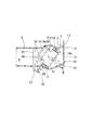
一方、送風方向を左右に調整する場合、操作ノブ5のノブ本体6をノブ軸16上で左または右に移動させて調整する。送風方向を例えば左に向ける場合、操作ノブ5のノブ本体6を持って左に動かすと、ノブ本体6と共にノブ保持部15がノブ軸16上を左に摺動し、これにより、ノブ保持部15の二股係合部15aが左側に移動し、偏倚軸3d、クランク3cを介して、バレル3の下部の回動軸3bが図7の時計方向に回り、これにより、バレル3が可動ルーバ4と共に上下の回動軸3a、3bを中心に回動し、バレル3の向きが左方向に向けられる。このとき、図7に示すように、バレル3が向けられた空気吹出口10の左側にはスリット開口部12があるため、通風路9を通りバレル3で左に曲げられた空気流は、主に左のスリット開口部12からスムーズに抜けて送風される。
On the other hand, when adjusting the air blowing direction to the left and right, the
同様に、操作ノブ5のノブ本体6を持って右に動かした場合には、ノブ保持部15、二股係合部15a、偏倚軸3d、クランク3cを介してバレル3の下部の回動軸3bが反時計方向に回り、バレル3が可動ルーバ4と共に上下の回動軸3a、3bを中心に回動し、バレル3の向きが右方向に向けられる。このときも、上記と同様、バレル3が向けられた空気吹出口10の右側にはスリット開口部12があるため、通風路9を通りバレル3で右に曲げられた空気流は、右のスリット開口部12からスムーズに抜けて送風され、風を受けた乗員には十分な風速感やスポット感が得られることとなる。
Similarly, when the
このように、バレル3を左右に回動させて風向調整した際、格子部13の両側のスリット開口部12,12から効果的に送風を行なって、風向調整時の風速感やスポット感を向上させることができる。また、格子部13によりレジスタ前面の空気吹出口を覆ってレジスタ内部を視覚的に非透過性としているので、レジスタ前面の意匠性や見栄えが改善される一方、両側にスリット開口部12,12を設けているので、特に風向を左右に調整した際の風の抜けを良くして、送風時の圧力損失を抑制することができる。
As described above, when the wind direction is adjusted by rotating the
なお、上記実施形態では、縦長の空気吹出口10の中央縦方向に格子部13を設け、その両側にスリット開口部12,12を配置したが、スリット開口部は格子部の上部と下部に設けることもできる。
In the above embodiment, the
また、上記では、縦に細長い形状の空気吹出口10を有したレジスタについて説明したが、それを90度回転させた状態とし、横長の空気吹出口を設けてベゼルを構成し、その空気吹出口内にバレルを横方向に向けて配置し、そのバレル内に複数の縦フィンを有した可動ルーバを配設することもできる。
In the above description, the register having the vertically
また、上記では、正面板11の空気吹出口10の下側に操作ノブ5を配設したが、バレルの回動操作用及び可動ルーバ操作用の操作ノブは、左右の側部など任意の位置に配設することができる。
In the above description, the
1 ベゼル
2 リテーナ
3 バレル
4 可動ルーバ
5 操作ノブ
6 ノブ本体
9 通風路
10 空気吹出口
11 正面板
12 スリット開口部
13 格子部
14 ノブ用開口部
15 ノブ保持部
16 ノブ軸
17 クランク
18 係止部
21 係止受部
22 軸受部
24 水平軸受部
25 ノブ軸受部
31 横フィン
32 フィン軸
33 リンクバー
34 円弧状リンク
35 フィン回動軸
DESCRIPTION OF
Claims (3)
該バレル内に可動ルーバが、複数のフィンを該バレルの回動軸と直交する軸の回りで回動可能に軸支して設けられ、
操作ノブが、該バレルを該回動軸の回りで回動させ、且つ該可動ルーバの各フィンを該軸の回りで回動させて風向を調整するように設けられ、
レジスタの前面がレジスタの前部を形成するベゼルの正面板により一体形成され、
該正面板は縦長に形成されるとともに、上下長手方向に湾曲して形成され、
該正面板の中央部に前記空気吹出口が縦長の長方形状に形成され、
該空気吹出口の正面を略覆うように格子部が設けられ、
該格子部の両側にスリット開口部が該空気吹出口の長手方向に向けて設けられたことを特徴とするレジスタ。 In a register having an elongated air outlet that is long in the longitudinal direction and short in the lateral direction, and a barrel pivotally supported around the longitudinal axis inside the air outlet,
A movable louver is provided in the barrel such that a plurality of fins are pivotally supported around an axis orthogonal to the rotation axis of the barrel.
An operation knob is provided to rotate the barrel about the rotation axis and adjust the wind direction by rotating the fins of the movable louver about the axis;
The front surface of the register is integrally formed by the front plate of the bezel that forms the front of the register,
The front plate is formed in a vertically long shape and is curved in the vertical direction.
The air outlet is formed in a vertically long rectangular shape at the center of the front plate,
A lattice portion is provided so as to substantially cover the front of the air outlet,
A resistor, wherein slit openings are provided on both sides of the lattice portion in the longitudinal direction of the air outlet.
該ノブ用開口部に前記操作ノブが配設されたことを特徴とする請求項1記載のレジスタ。 A knob opening is provided at an edge of the front plate,
2. The register according to claim 1, wherein the operation knob is disposed in the knob opening.
該ノブ本体にはノブ保持部が該ノブ本体と共に移動可能に設けられ、
該ノブ本体の軸方向の動きを、該ノブ保持部を介して前記バレルの回動軸に伝達して回動させるバレルリンク機構が設けられ、
該ノブ本体の回動を前記可動ルーバの各フィンに伝達して傾動させる可動ルーバリンク機構が設けられたことを特徴とする請求項2記載のレジスタ。 The operation knob is configured such that a knob body is slidably supported on a knob shaft supported horizontally on the lower side of the front plate of the bezel,
The knob body is provided with a knob holding portion so as to be movable together with the knob body.
A barrel link mechanism is provided that transmits the movement of the knob body in the axial direction to the rotation shaft of the barrel via the knob holding portion, and rotates.
3. The register according to claim 2, further comprising a movable louver link mechanism that transmits the rotation of the knob body to each fin of the movable louver to tilt the knob body.
Priority Applications (1)
| Application Number | Priority Date | Filing Date | Title |
|---|---|---|---|
| JP2010018912A JP5529564B2 (en) | 2010-01-29 | 2010-01-29 | register |
Applications Claiming Priority (1)
| Application Number | Priority Date | Filing Date | Title |
|---|---|---|---|
| JP2010018912A JP5529564B2 (en) | 2010-01-29 | 2010-01-29 | register |
Publications (2)
| Publication Number | Publication Date |
|---|---|
| JP2011156930A JP2011156930A (en) | 2011-08-18 |
| JP5529564B2 true JP5529564B2 (en) | 2014-06-25 |
Family
ID=44589290
Family Applications (1)
| Application Number | Title | Priority Date | Filing Date |
|---|---|---|---|
| JP2010018912A Expired - Fee Related JP5529564B2 (en) | 2010-01-29 | 2010-01-29 | register |
Country Status (1)
| Country | Link |
|---|---|
| JP (1) | JP5529564B2 (en) |
Families Citing this family (5)
| Publication number | Priority date | Publication date | Assignee | Title |
|---|---|---|---|---|
| JP5834784B2 (en) * | 2011-11-04 | 2015-12-24 | トヨタ紡織株式会社 | Vehicle seat |
| JP6239858B2 (en) * | 2013-05-14 | 2017-11-29 | 豊和化成株式会社 | register |
| DE102017118450A1 (en) * | 2017-08-14 | 2019-02-14 | Illinois Tool Works Inc. | Air vents for a vehicle |
| EP3722126B1 (en) * | 2019-04-09 | 2023-06-07 | Volvo Car Corporation | Air vent |
| JP7394541B2 (en) * | 2019-05-17 | 2023-12-08 | 日本プラスト株式会社 | Wind direction adjustment device |
Family Cites Families (7)
| Publication number | Priority date | Publication date | Assignee | Title |
|---|---|---|---|---|
| JP2602272Y2 (en) * | 1991-09-18 | 2000-01-11 | 本田技研工業株式会社 | Air outlet structure of vehicle air conditioner |
| ES2128420T3 (en) * | 1992-03-17 | 1999-05-16 | Bowles Fluidics Corp | NOZZLE AND METHOD TO DISCHARGE AIR. |
| JPH05332602A (en) * | 1992-05-30 | 1993-12-14 | Suzuki Motor Corp | Support device for air conditioning grille |
| JP4150462B2 (en) * | 1999-05-14 | 2008-09-17 | 豊和化成株式会社 | Air blowout adjustment register |
| JP2004249912A (en) * | 2003-02-21 | 2004-09-09 | Howa Kasei Kk | Register |
| JP2009166518A (en) * | 2008-01-10 | 2009-07-30 | Howa Kasei Kk | Register |
| JP3156703U (en) * | 2009-10-28 | 2010-01-14 | 豊和化成株式会社 | register |
-
2010
- 2010-01-29 JP JP2010018912A patent/JP5529564B2/en not_active Expired - Fee Related
Also Published As
| Publication number | Publication date |
|---|---|
| JP2011156930A (en) | 2011-08-18 |
Similar Documents
| Publication | Publication Date | Title |
|---|---|---|
| JP6104534B2 (en) | register | |
| JP5577108B2 (en) | register | |
| JP5892127B2 (en) | Air conditioning register | |
| JP5210119B2 (en) | register | |
| JP3176607U (en) | Register operation knob device | |
| JP5028254B2 (en) | register | |
| JP5529564B2 (en) | register | |
| JP5656957B2 (en) | register | |
| JP2019098878A (en) | register | |
| JP6077375B2 (en) | Register operation knob | |
| JP2008149830A (en) | Thin register for air-conditioning | |
| JP6066714B2 (en) | register | |
| JP3572480B2 (en) | Wind direction adjustment mechanism of automotive register | |
| JP2014088115A (en) | Register | |
| JP2011251590A (en) | Wind direction adjusting device | |
| JP2009166518A (en) | Register | |
| JP2009018634A (en) | Register for air blow-off adjustment | |
| JP2014172549A (en) | Register | |
| JP2018065471A (en) | register | |
| JP2017177979A (en) | register | |
| JP2013023082A (en) | Register | |
| JP3161206U (en) | register | |
| JP2015033905A (en) | Register | |
| JP5623939B2 (en) | register | |
| JP5937447B2 (en) | Wind direction adjustment device |
Legal Events
| Date | Code | Title | Description |
|---|---|---|---|
| A711 | Notification of change in applicant |
Free format text: JAPANESE INTERMEDIATE CODE: A711 Effective date: 20110725 |
|
| A521 | Written amendment |
Free format text: JAPANESE INTERMEDIATE CODE: A821 Effective date: 20110726 |
|
| A521 | Written amendment |
Free format text: JAPANESE INTERMEDIATE CODE: A523 Effective date: 20110915 |
|
| A621 | Written request for application examination |
Free format text: JAPANESE INTERMEDIATE CODE: A621 Effective date: 20130111 |
|
| A977 | Report on retrieval |
Free format text: JAPANESE INTERMEDIATE CODE: A971007 Effective date: 20131022 |
|
| A131 | Notification of reasons for refusal |
Free format text: JAPANESE INTERMEDIATE CODE: A131 Effective date: 20131029 |
|
| A977 | Report on retrieval |
Free format text: JAPANESE INTERMEDIATE CODE: A971007 Effective date: 20131129 |
|
| A521 | Written amendment |
Free format text: JAPANESE INTERMEDIATE CODE: A821 Effective date: 20131211 Free format text: JAPANESE INTERMEDIATE CODE: A523 Effective date: 20131211 |
|
| RD02 | Notification of acceptance of power of attorney |
Free format text: JAPANESE INTERMEDIATE CODE: A7422 Effective date: 20131211 |
|
| A521 | Written amendment |
Free format text: JAPANESE INTERMEDIATE CODE: A821 Effective date: 20131211 |
|
| TRDD | Decision of grant or rejection written | ||
| A01 | Written decision to grant a patent or to grant a registration (utility model) |
Free format text: JAPANESE INTERMEDIATE CODE: A01 Effective date: 20140401 |
|
| A61 | First payment of annual fees (during grant procedure) |
Free format text: JAPANESE INTERMEDIATE CODE: A61 Effective date: 20140417 |
|
| R150 | Certificate of patent or registration of utility model |
Ref document number: 5529564 Country of ref document: JP Free format text: JAPANESE INTERMEDIATE CODE: R150 |
|
| LAPS | Cancellation because of no payment of annual fees |