EP1289878B1 - Fuel reforming system - Google Patents
Fuel reforming system Download PDFInfo
- Publication number
- EP1289878B1 EP1289878B1 EP01926145A EP01926145A EP1289878B1 EP 1289878 B1 EP1289878 B1 EP 1289878B1 EP 01926145 A EP01926145 A EP 01926145A EP 01926145 A EP01926145 A EP 01926145A EP 1289878 B1 EP1289878 B1 EP 1289878B1
- Authority
- EP
- European Patent Office
- Prior art keywords
- fuel
- flow rate
- vapors
- oxygen
- gas
- Prior art date
- Legal status (The legal status is an assumption and is not a legal conclusion. Google has not performed a legal analysis and makes no representation as to the accuracy of the status listed.)
- Expired - Lifetime
Links
Images


Classifications
-
- H—ELECTRICITY
- H01—ELECTRIC ELEMENTS
- H01M—PROCESSES OR MEANS, e.g. BATTERIES, FOR THE DIRECT CONVERSION OF CHEMICAL ENERGY INTO ELECTRICAL ENERGY
- H01M8/00—Fuel cells; Manufacture thereof
- H01M8/04—Auxiliary arrangements, e.g. for control of pressure or for circulation of fluids
- H01M8/04298—Processes for controlling fuel cells or fuel cell systems
- H01M8/04313—Processes for controlling fuel cells or fuel cell systems characterised by the detection or assessment of variables; characterised by the detection or assessment of failure or abnormal function
- H01M8/0438—Pressure; Ambient pressure; Flow
- H01M8/04425—Pressure; Ambient pressure; Flow at auxiliary devices, e.g. reformers, compressors, burners
-
- H—ELECTRICITY
- H01—ELECTRIC ELEMENTS
- H01M—PROCESSES OR MEANS, e.g. BATTERIES, FOR THE DIRECT CONVERSION OF CHEMICAL ENERGY INTO ELECTRICAL ENERGY
- H01M8/00—Fuel cells; Manufacture thereof
- H01M8/06—Combination of fuel cells with means for production of reactants or for treatment of residues
-
- B—PERFORMING OPERATIONS; TRANSPORTING
- B01—PHYSICAL OR CHEMICAL PROCESSES OR APPARATUS IN GENERAL
- B01B—BOILING; BOILING APPARATUS ; EVAPORATION; EVAPORATION APPARATUS
- B01B1/00—Boiling; Boiling apparatus for physical or chemical purposes ; Evaporation in general
-
- B—PERFORMING OPERATIONS; TRANSPORTING
- B01—PHYSICAL OR CHEMICAL PROCESSES OR APPARATUS IN GENERAL
- B01B—BOILING; BOILING APPARATUS ; EVAPORATION; EVAPORATION APPARATUS
- B01B1/00—Boiling; Boiling apparatus for physical or chemical purposes ; Evaporation in general
- B01B1/005—Evaporation for physical or chemical purposes; Evaporation apparatus therefor, e.g. evaporation of liquids for gas phase reactions
-
- B—PERFORMING OPERATIONS; TRANSPORTING
- B01—PHYSICAL OR CHEMICAL PROCESSES OR APPARATUS IN GENERAL
- B01J—CHEMICAL OR PHYSICAL PROCESSES, e.g. CATALYSIS OR COLLOID CHEMISTRY; THEIR RELEVANT APPARATUS
- B01J19/00—Chemical, physical or physico-chemical processes in general; Their relevant apparatus
- B01J19/0006—Controlling or regulating processes
-
- B—PERFORMING OPERATIONS; TRANSPORTING
- B01—PHYSICAL OR CHEMICAL PROCESSES OR APPARATUS IN GENERAL
- B01J—CHEMICAL OR PHYSICAL PROCESSES, e.g. CATALYSIS OR COLLOID CHEMISTRY; THEIR RELEVANT APPARATUS
- B01J8/00—Chemical or physical processes in general, conducted in the presence of fluids and solid particles; Apparatus for such processes
- B01J8/001—Controlling catalytic processes
-
- C—CHEMISTRY; METALLURGY
- C01—INORGANIC CHEMISTRY
- C01B—NON-METALLIC ELEMENTS; COMPOUNDS THEREOF; METALLOIDS OR COMPOUNDS THEREOF NOT COVERED BY SUBCLASS C01C
- C01B3/00—Hydrogen; Gaseous mixtures containing hydrogen; Separation of hydrogen from mixtures containing it; Purification of hydrogen
- C01B3/02—Production of hydrogen or of gaseous mixtures containing a substantial proportion of hydrogen
- C01B3/32—Production of hydrogen or of gaseous mixtures containing a substantial proportion of hydrogen by reaction of gaseous or liquid organic compounds with gasifying agents, e.g. water, carbon dioxide, air
- C01B3/323—Catalytic reaction of gaseous or liquid organic compounds other than hydrocarbons with gasifying agents
-
- C—CHEMISTRY; METALLURGY
- C01—INORGANIC CHEMISTRY
- C01B—NON-METALLIC ELEMENTS; COMPOUNDS THEREOF; METALLOIDS OR COMPOUNDS THEREOF NOT COVERED BY SUBCLASS C01C
- C01B3/00—Hydrogen; Gaseous mixtures containing hydrogen; Separation of hydrogen from mixtures containing it; Purification of hydrogen
- C01B3/02—Production of hydrogen or of gaseous mixtures containing a substantial proportion of hydrogen
- C01B3/32—Production of hydrogen or of gaseous mixtures containing a substantial proportion of hydrogen by reaction of gaseous or liquid organic compounds with gasifying agents, e.g. water, carbon dioxide, air
- C01B3/34—Production of hydrogen or of gaseous mixtures containing a substantial proportion of hydrogen by reaction of gaseous or liquid organic compounds with gasifying agents, e.g. water, carbon dioxide, air by reaction of hydrocarbons with gasifying agents
- C01B3/48—Production of hydrogen or of gaseous mixtures containing a substantial proportion of hydrogen by reaction of gaseous or liquid organic compounds with gasifying agents, e.g. water, carbon dioxide, air by reaction of hydrocarbons with gasifying agents followed by reaction of water vapour with carbon monoxide
-
- C—CHEMISTRY; METALLURGY
- C01—INORGANIC CHEMISTRY
- C01B—NON-METALLIC ELEMENTS; COMPOUNDS THEREOF; METALLOIDS OR COMPOUNDS THEREOF NOT COVERED BY SUBCLASS C01C
- C01B3/00—Hydrogen; Gaseous mixtures containing hydrogen; Separation of hydrogen from mixtures containing it; Purification of hydrogen
- C01B3/50—Separation of hydrogen or hydrogen containing gases from gaseous mixtures, e.g. purification
- C01B3/56—Separation of hydrogen or hydrogen containing gases from gaseous mixtures, e.g. purification by contacting with solids; Regeneration of used solids
- C01B3/58—Separation of hydrogen or hydrogen containing gases from gaseous mixtures, e.g. purification by contacting with solids; Regeneration of used solids including a catalytic reaction
- C01B3/583—Separation of hydrogen or hydrogen containing gases from gaseous mixtures, e.g. purification by contacting with solids; Regeneration of used solids including a catalytic reaction the reaction being the selective oxidation of carbon monoxide
-
- H—ELECTRICITY
- H01—ELECTRIC ELEMENTS
- H01M—PROCESSES OR MEANS, e.g. BATTERIES, FOR THE DIRECT CONVERSION OF CHEMICAL ENERGY INTO ELECTRICAL ENERGY
- H01M8/00—Fuel cells; Manufacture thereof
- H01M8/04—Auxiliary arrangements, e.g. for control of pressure or for circulation of fluids
- H01M8/04298—Processes for controlling fuel cells or fuel cell systems
- H01M8/04313—Processes for controlling fuel cells or fuel cell systems characterised by the detection or assessment of variables; characterised by the detection or assessment of failure or abnormal function
- H01M8/0432—Temperature; Ambient temperature
- H01M8/04373—Temperature; Ambient temperature of auxiliary devices, e.g. reformers, compressors, burners
-
- H—ELECTRICITY
- H01—ELECTRIC ELEMENTS
- H01M—PROCESSES OR MEANS, e.g. BATTERIES, FOR THE DIRECT CONVERSION OF CHEMICAL ENERGY INTO ELECTRICAL ENERGY
- H01M8/00—Fuel cells; Manufacture thereof
- H01M8/04—Auxiliary arrangements, e.g. for control of pressure or for circulation of fluids
- H01M8/04298—Processes for controlling fuel cells or fuel cell systems
- H01M8/04313—Processes for controlling fuel cells or fuel cell systems characterised by the detection or assessment of variables; characterised by the detection or assessment of failure or abnormal function
- H01M8/0438—Pressure; Ambient pressure; Flow
- H01M8/04402—Pressure; Ambient pressure; Flow of anode exhausts
-
- H—ELECTRICITY
- H01—ELECTRIC ELEMENTS
- H01M—PROCESSES OR MEANS, e.g. BATTERIES, FOR THE DIRECT CONVERSION OF CHEMICAL ENERGY INTO ELECTRICAL ENERGY
- H01M8/00—Fuel cells; Manufacture thereof
- H01M8/04—Auxiliary arrangements, e.g. for control of pressure or for circulation of fluids
- H01M8/04298—Processes for controlling fuel cells or fuel cell systems
- H01M8/04313—Processes for controlling fuel cells or fuel cell systems characterised by the detection or assessment of variables; characterised by the detection or assessment of failure or abnormal function
- H01M8/0438—Pressure; Ambient pressure; Flow
- H01M8/0441—Pressure; Ambient pressure; Flow of cathode exhausts
-
- H—ELECTRICITY
- H01—ELECTRIC ELEMENTS
- H01M—PROCESSES OR MEANS, e.g. BATTERIES, FOR THE DIRECT CONVERSION OF CHEMICAL ENERGY INTO ELECTRICAL ENERGY
- H01M8/00—Fuel cells; Manufacture thereof
- H01M8/04—Auxiliary arrangements, e.g. for control of pressure or for circulation of fluids
- H01M8/04298—Processes for controlling fuel cells or fuel cell systems
- H01M8/04694—Processes for controlling fuel cells or fuel cell systems characterised by variables to be controlled
- H01M8/04746—Pressure; Flow
- H01M8/04776—Pressure; Flow at auxiliary devices, e.g. reformer, compressor, burner
-
- H—ELECTRICITY
- H01—ELECTRIC ELEMENTS
- H01M—PROCESSES OR MEANS, e.g. BATTERIES, FOR THE DIRECT CONVERSION OF CHEMICAL ENERGY INTO ELECTRICAL ENERGY
- H01M8/00—Fuel cells; Manufacture thereof
- H01M8/04—Auxiliary arrangements, e.g. for control of pressure or for circulation of fluids
- H01M8/04298—Processes for controlling fuel cells or fuel cell systems
- H01M8/04694—Processes for controlling fuel cells or fuel cell systems characterised by variables to be controlled
- H01M8/04828—Humidity; Water content
-
- B—PERFORMING OPERATIONS; TRANSPORTING
- B01—PHYSICAL OR CHEMICAL PROCESSES OR APPARATUS IN GENERAL
- B01J—CHEMICAL OR PHYSICAL PROCESSES, e.g. CATALYSIS OR COLLOID CHEMISTRY; THEIR RELEVANT APPARATUS
- B01J2219/00—Chemical, physical or physico-chemical processes in general; Their relevant apparatus
- B01J2219/00049—Controlling or regulating processes
- B01J2219/00051—Controlling the temperature
- B01J2219/00054—Controlling or regulating the heat exchange system
- B01J2219/00056—Controlling or regulating the heat exchange system involving measured parameters
- B01J2219/00058—Temperature measurement
- B01J2219/00063—Temperature measurement of the reactants
-
- B—PERFORMING OPERATIONS; TRANSPORTING
- B01—PHYSICAL OR CHEMICAL PROCESSES OR APPARATUS IN GENERAL
- B01J—CHEMICAL OR PHYSICAL PROCESSES, e.g. CATALYSIS OR COLLOID CHEMISTRY; THEIR RELEVANT APPARATUS
- B01J2219/00—Chemical, physical or physico-chemical processes in general; Their relevant apparatus
- B01J2219/00049—Controlling or regulating processes
- B01J2219/00164—Controlling or regulating processes controlling the flow
-
- B—PERFORMING OPERATIONS; TRANSPORTING
- B01—PHYSICAL OR CHEMICAL PROCESSES OR APPARATUS IN GENERAL
- B01J—CHEMICAL OR PHYSICAL PROCESSES, e.g. CATALYSIS OR COLLOID CHEMISTRY; THEIR RELEVANT APPARATUS
- B01J2219/00—Chemical, physical or physico-chemical processes in general; Their relevant apparatus
- B01J2219/00049—Controlling or regulating processes
- B01J2219/00191—Control algorithm
- B01J2219/00193—Sensing a parameter
- B01J2219/00195—Sensing a parameter of the reaction system
- B01J2219/00198—Sensing a parameter of the reaction system at the reactor inlet
-
- B—PERFORMING OPERATIONS; TRANSPORTING
- B01—PHYSICAL OR CHEMICAL PROCESSES OR APPARATUS IN GENERAL
- B01J—CHEMICAL OR PHYSICAL PROCESSES, e.g. CATALYSIS OR COLLOID CHEMISTRY; THEIR RELEVANT APPARATUS
- B01J2219/00—Chemical, physical or physico-chemical processes in general; Their relevant apparatus
- B01J2219/00049—Controlling or regulating processes
- B01J2219/00191—Control algorithm
- B01J2219/00211—Control algorithm comparing a sensed parameter with a pre-set value
- B01J2219/00218—Dynamically variable (in-line) parameter values
-
- B—PERFORMING OPERATIONS; TRANSPORTING
- B01—PHYSICAL OR CHEMICAL PROCESSES OR APPARATUS IN GENERAL
- B01J—CHEMICAL OR PHYSICAL PROCESSES, e.g. CATALYSIS OR COLLOID CHEMISTRY; THEIR RELEVANT APPARATUS
- B01J2219/00—Chemical, physical or physico-chemical processes in general; Their relevant apparatus
- B01J2219/00049—Controlling or regulating processes
- B01J2219/00191—Control algorithm
- B01J2219/00222—Control algorithm taking actions
- B01J2219/00227—Control algorithm taking actions modifying the operating conditions
- B01J2219/00229—Control algorithm taking actions modifying the operating conditions of the reaction system
- B01J2219/00231—Control algorithm taking actions modifying the operating conditions of the reaction system at the reactor inlet
-
- C—CHEMISTRY; METALLURGY
- C01—INORGANIC CHEMISTRY
- C01B—NON-METALLIC ELEMENTS; COMPOUNDS THEREOF; METALLOIDS OR COMPOUNDS THEREOF NOT COVERED BY SUBCLASS C01C
- C01B2203/00—Integrated processes for the production of hydrogen or synthesis gas
- C01B2203/02—Processes for making hydrogen or synthesis gas
- C01B2203/0205—Processes for making hydrogen or synthesis gas containing a reforming step
- C01B2203/0227—Processes for making hydrogen or synthesis gas containing a reforming step containing a catalytic reforming step
- C01B2203/0244—Processes for making hydrogen or synthesis gas containing a reforming step containing a catalytic reforming step the reforming step being an autothermal reforming step, e.g. secondary reforming processes
-
- C—CHEMISTRY; METALLURGY
- C01—INORGANIC CHEMISTRY
- C01B—NON-METALLIC ELEMENTS; COMPOUNDS THEREOF; METALLOIDS OR COMPOUNDS THEREOF NOT COVERED BY SUBCLASS C01C
- C01B2203/00—Integrated processes for the production of hydrogen or synthesis gas
- C01B2203/02—Processes for making hydrogen or synthesis gas
- C01B2203/0283—Processes for making hydrogen or synthesis gas containing a CO-shift step, i.e. a water gas shift step
-
- C—CHEMISTRY; METALLURGY
- C01—INORGANIC CHEMISTRY
- C01B—NON-METALLIC ELEMENTS; COMPOUNDS THEREOF; METALLOIDS OR COMPOUNDS THEREOF NOT COVERED BY SUBCLASS C01C
- C01B2203/00—Integrated processes for the production of hydrogen or synthesis gas
- C01B2203/04—Integrated processes for the production of hydrogen or synthesis gas containing a purification step for the hydrogen or the synthesis gas
- C01B2203/0435—Catalytic purification
- C01B2203/044—Selective oxidation of carbon monoxide
-
- C—CHEMISTRY; METALLURGY
- C01—INORGANIC CHEMISTRY
- C01B—NON-METALLIC ELEMENTS; COMPOUNDS THEREOF; METALLOIDS OR COMPOUNDS THEREOF NOT COVERED BY SUBCLASS C01C
- C01B2203/00—Integrated processes for the production of hydrogen or synthesis gas
- C01B2203/04—Integrated processes for the production of hydrogen or synthesis gas containing a purification step for the hydrogen or the synthesis gas
- C01B2203/0465—Composition of the impurity
- C01B2203/047—Composition of the impurity the impurity being carbon monoxide
-
- C—CHEMISTRY; METALLURGY
- C01—INORGANIC CHEMISTRY
- C01B—NON-METALLIC ELEMENTS; COMPOUNDS THEREOF; METALLOIDS OR COMPOUNDS THEREOF NOT COVERED BY SUBCLASS C01C
- C01B2203/00—Integrated processes for the production of hydrogen or synthesis gas
- C01B2203/06—Integration with other chemical processes
- C01B2203/066—Integration with other chemical processes with fuel cells
-
- C—CHEMISTRY; METALLURGY
- C01—INORGANIC CHEMISTRY
- C01B—NON-METALLIC ELEMENTS; COMPOUNDS THEREOF; METALLOIDS OR COMPOUNDS THEREOF NOT COVERED BY SUBCLASS C01C
- C01B2203/00—Integrated processes for the production of hydrogen or synthesis gas
- C01B2203/08—Methods of heating or cooling
- C01B2203/0805—Methods of heating the process for making hydrogen or synthesis gas
- C01B2203/0811—Methods of heating the process for making hydrogen or synthesis gas by combustion of fuel
- C01B2203/0822—Methods of heating the process for making hydrogen or synthesis gas by combustion of fuel the fuel containing hydrogen
-
- C—CHEMISTRY; METALLURGY
- C01—INORGANIC CHEMISTRY
- C01B—NON-METALLIC ELEMENTS; COMPOUNDS THEREOF; METALLOIDS OR COMPOUNDS THEREOF NOT COVERED BY SUBCLASS C01C
- C01B2203/00—Integrated processes for the production of hydrogen or synthesis gas
- C01B2203/08—Methods of heating or cooling
- C01B2203/0805—Methods of heating the process for making hydrogen or synthesis gas
- C01B2203/0811—Methods of heating the process for making hydrogen or synthesis gas by combustion of fuel
- C01B2203/0827—Methods of heating the process for making hydrogen or synthesis gas by combustion of fuel at least part of the fuel being a recycle stream
-
- C—CHEMISTRY; METALLURGY
- C01—INORGANIC CHEMISTRY
- C01B—NON-METALLIC ELEMENTS; COMPOUNDS THEREOF; METALLOIDS OR COMPOUNDS THEREOF NOT COVERED BY SUBCLASS C01C
- C01B2203/00—Integrated processes for the production of hydrogen or synthesis gas
- C01B2203/08—Methods of heating or cooling
- C01B2203/0805—Methods of heating the process for making hydrogen or synthesis gas
- C01B2203/0838—Methods of heating the process for making hydrogen or synthesis gas by heat exchange with exothermic reactions, other than by combustion of fuel
- C01B2203/0844—Methods of heating the process for making hydrogen or synthesis gas by heat exchange with exothermic reactions, other than by combustion of fuel the non-combustive exothermic reaction being another reforming reaction as defined in groups C01B2203/02 - C01B2203/0294
-
- C—CHEMISTRY; METALLURGY
- C01—INORGANIC CHEMISTRY
- C01B—NON-METALLIC ELEMENTS; COMPOUNDS THEREOF; METALLOIDS OR COMPOUNDS THEREOF NOT COVERED BY SUBCLASS C01C
- C01B2203/00—Integrated processes for the production of hydrogen or synthesis gas
- C01B2203/08—Methods of heating or cooling
- C01B2203/0805—Methods of heating the process for making hydrogen or synthesis gas
- C01B2203/0866—Methods of heating the process for making hydrogen or synthesis gas by combination of different heating methods
-
- C—CHEMISTRY; METALLURGY
- C01—INORGANIC CHEMISTRY
- C01B—NON-METALLIC ELEMENTS; COMPOUNDS THEREOF; METALLOIDS OR COMPOUNDS THEREOF NOT COVERED BY SUBCLASS C01C
- C01B2203/00—Integrated processes for the production of hydrogen or synthesis gas
- C01B2203/12—Feeding the process for making hydrogen or synthesis gas
- C01B2203/1205—Composition of the feed
- C01B2203/1211—Organic compounds or organic mixtures used in the process for making hydrogen or synthesis gas
- C01B2203/1217—Alcohols
- C01B2203/1223—Methanol
-
- C—CHEMISTRY; METALLURGY
- C01—INORGANIC CHEMISTRY
- C01B—NON-METALLIC ELEMENTS; COMPOUNDS THEREOF; METALLOIDS OR COMPOUNDS THEREOF NOT COVERED BY SUBCLASS C01C
- C01B2203/00—Integrated processes for the production of hydrogen or synthesis gas
- C01B2203/12—Feeding the process for making hydrogen or synthesis gas
- C01B2203/1205—Composition of the feed
- C01B2203/1211—Organic compounds or organic mixtures used in the process for making hydrogen or synthesis gas
- C01B2203/1235—Hydrocarbons
-
- C—CHEMISTRY; METALLURGY
- C01—INORGANIC CHEMISTRY
- C01B—NON-METALLIC ELEMENTS; COMPOUNDS THEREOF; METALLOIDS OR COMPOUNDS THEREOF NOT COVERED BY SUBCLASS C01C
- C01B2203/00—Integrated processes for the production of hydrogen or synthesis gas
- C01B2203/12—Feeding the process for making hydrogen or synthesis gas
- C01B2203/1276—Mixing of different feed components
-
- C—CHEMISTRY; METALLURGY
- C01—INORGANIC CHEMISTRY
- C01B—NON-METALLIC ELEMENTS; COMPOUNDS THEREOF; METALLOIDS OR COMPOUNDS THEREOF NOT COVERED BY SUBCLASS C01C
- C01B2203/00—Integrated processes for the production of hydrogen or synthesis gas
- C01B2203/12—Feeding the process for making hydrogen or synthesis gas
- C01B2203/1288—Evaporation of one or more of the different feed components
-
- C—CHEMISTRY; METALLURGY
- C01—INORGANIC CHEMISTRY
- C01B—NON-METALLIC ELEMENTS; COMPOUNDS THEREOF; METALLOIDS OR COMPOUNDS THEREOF NOT COVERED BY SUBCLASS C01C
- C01B2203/00—Integrated processes for the production of hydrogen or synthesis gas
- C01B2203/14—Details of the flowsheet
- C01B2203/142—At least two reforming, decomposition or partial oxidation steps in series
-
- C—CHEMISTRY; METALLURGY
- C01—INORGANIC CHEMISTRY
- C01B—NON-METALLIC ELEMENTS; COMPOUNDS THEREOF; METALLOIDS OR COMPOUNDS THEREOF NOT COVERED BY SUBCLASS C01C
- C01B2203/00—Integrated processes for the production of hydrogen or synthesis gas
- C01B2203/16—Controlling the process
- C01B2203/1614—Controlling the temperature
- C01B2203/1619—Measuring the temperature
-
- C—CHEMISTRY; METALLURGY
- C01—INORGANIC CHEMISTRY
- C01B—NON-METALLIC ELEMENTS; COMPOUNDS THEREOF; METALLOIDS OR COMPOUNDS THEREOF NOT COVERED BY SUBCLASS C01C
- C01B2203/00—Integrated processes for the production of hydrogen or synthesis gas
- C01B2203/16—Controlling the process
- C01B2203/1628—Controlling the pressure
- C01B2203/1633—Measuring the pressure
-
- C—CHEMISTRY; METALLURGY
- C01—INORGANIC CHEMISTRY
- C01B—NON-METALLIC ELEMENTS; COMPOUNDS THEREOF; METALLOIDS OR COMPOUNDS THEREOF NOT COVERED BY SUBCLASS C01C
- C01B2203/00—Integrated processes for the production of hydrogen or synthesis gas
- C01B2203/16—Controlling the process
- C01B2203/1628—Controlling the pressure
- C01B2203/1638—Adjusting the pressure
-
- C—CHEMISTRY; METALLURGY
- C01—INORGANIC CHEMISTRY
- C01B—NON-METALLIC ELEMENTS; COMPOUNDS THEREOF; METALLOIDS OR COMPOUNDS THEREOF NOT COVERED BY SUBCLASS C01C
- C01B2203/00—Integrated processes for the production of hydrogen or synthesis gas
- C01B2203/16—Controlling the process
- C01B2203/169—Controlling the feed
-
- C—CHEMISTRY; METALLURGY
- C01—INORGANIC CHEMISTRY
- C01B—NON-METALLIC ELEMENTS; COMPOUNDS THEREOF; METALLOIDS OR COMPOUNDS THEREOF NOT COVERED BY SUBCLASS C01C
- C01B2203/00—Integrated processes for the production of hydrogen or synthesis gas
- C01B2203/80—Aspect of integrated processes for the production of hydrogen or synthesis gas not covered by groups C01B2203/02 - C01B2203/1695
- C01B2203/82—Several process steps of C01B2203/02 - C01B2203/08 integrated into a single apparatus
-
- H—ELECTRICITY
- H01—ELECTRIC ELEMENTS
- H01M—PROCESSES OR MEANS, e.g. BATTERIES, FOR THE DIRECT CONVERSION OF CHEMICAL ENERGY INTO ELECTRICAL ENERGY
- H01M8/00—Fuel cells; Manufacture thereof
- H01M8/04—Auxiliary arrangements, e.g. for control of pressure or for circulation of fluids
- H01M8/04298—Processes for controlling fuel cells or fuel cell systems
- H01M8/04992—Processes for controlling fuel cells or fuel cell systems characterised by the implementation of mathematical or computational algorithms, e.g. feedback control loops, fuzzy logic, neural networks or artificial intelligence
-
- H—ELECTRICITY
- H01—ELECTRIC ELEMENTS
- H01M—PROCESSES OR MEANS, e.g. BATTERIES, FOR THE DIRECT CONVERSION OF CHEMICAL ENERGY INTO ELECTRICAL ENERGY
- H01M8/00—Fuel cells; Manufacture thereof
- H01M8/06—Combination of fuel cells with means for production of reactants or for treatment of residues
- H01M8/0606—Combination of fuel cells with means for production of reactants or for treatment of residues with means for production of gaseous reactants
- H01M8/0612—Combination of fuel cells with means for production of reactants or for treatment of residues with means for production of gaseous reactants from carbon-containing material
-
- Y—GENERAL TAGGING OF NEW TECHNOLOGICAL DEVELOPMENTS; GENERAL TAGGING OF CROSS-SECTIONAL TECHNOLOGIES SPANNING OVER SEVERAL SECTIONS OF THE IPC; TECHNICAL SUBJECTS COVERED BY FORMER USPC CROSS-REFERENCE ART COLLECTIONS [XRACs] AND DIGESTS
- Y02—TECHNOLOGIES OR APPLICATIONS FOR MITIGATION OR ADAPTATION AGAINST CLIMATE CHANGE
- Y02E—REDUCTION OF GREENHOUSE GAS [GHG] EMISSIONS, RELATED TO ENERGY GENERATION, TRANSMISSION OR DISTRIBUTION
- Y02E60/00—Enabling technologies; Technologies with a potential or indirect contribution to GHG emissions mitigation
- Y02E60/30—Hydrogen technology
- Y02E60/50—Fuel cells
-
- Y—GENERAL TAGGING OF NEW TECHNOLOGICAL DEVELOPMENTS; GENERAL TAGGING OF CROSS-SECTIONAL TECHNOLOGIES SPANNING OVER SEVERAL SECTIONS OF THE IPC; TECHNICAL SUBJECTS COVERED BY FORMER USPC CROSS-REFERENCE ART COLLECTIONS [XRACs] AND DIGESTS
- Y02—TECHNOLOGIES OR APPLICATIONS FOR MITIGATION OR ADAPTATION AGAINST CLIMATE CHANGE
- Y02P—CLIMATE CHANGE MITIGATION TECHNOLOGIES IN THE PRODUCTION OR PROCESSING OF GOODS
- Y02P20/00—Technologies relating to chemical industry
- Y02P20/10—Process efficiency
Definitions
- the present invention relates to a fuel reforming device and a fuel reforming method.
- the prior art document EP 0 798 798 A2 teaches a method of and an apparatus for reforming fuel and the fuel cell system with a fuel reforming apparatus incorporated therein.
- Said apparatus comprises a reformer for generating a reformed gas containing the hydrogen by using a gas containing vapors of fuel supplied from an evaporator.
- a methanol tank for storing methanol and a water tank for storing water are connected to said evaporator.
- An air tank is provided for supplying air to said reformer.
- the evaporator receives methanol and water from the methanol tank and the water tank, wherein a pump is provided for controlling quantity of methanol supplied to the evaporator and a further pump is provided for controlling quantity of water supplied to the evaporator.
- a temperature sensor is arranged between the evaporator and a reformer and measures the temperature of the raw fuel gas. The result of the measurement is input as an electric signal into the control unit, wherein the pump for regulating quantities of methanol and water supplied to the evaporator are controlled in consideration of the temperature of the raw fuel gas vaporized in the evaporator and supplied to the reformer.
- a further temperature sensor is disposed downstream of the reformer and measures the temperature of the gaseous fuel discharged from the reformer. On the basis of said temperature, the related control unit determines the reaction temperature in the reformer and outputs a driving signal to a regulator so as to regulate the amount of air from the air tank to the reformer.
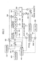
- a prior art of a fuel reforming system in a mobile fuel cell system represented by a fuel cell automobile is explained by referring to Fig. 1 .
- Amixed solution 101 of water and methanol used as fuel contained in a fuel tank 100 is sent into an evaporator 102, and heated and evaporated to form a mixed vapor 103 of water (steam) and methanol, and sent into a mixer 104.
- Air 106 is also sent into the mixer 104 from a compressor 105.
- the mixed steam 103 and air 106 are mixed in the mixer 104, and sent into an autothermal reforming reactor (ATR reactor) 107.
- ATR reactor autothermal reforming reactor
- the ATR reactor 107 reforms the methanol used as fuel by catalytic reaction shown in chemical reaction formulas Chem.1 and Chem.2 by using water and oxygen in air, and produces an oxygen-rich reformed gas.
- Chemical reaction formula Chem.1 shows steam reaction of methanol (endothermic reaction), and chemical reaction formula Chem.2 denotes partial oxidation reaction of methanol (exothermic reaction).
- the reaction in chemical reaction formula Chem.1 progresses in steps mainly as shown in chemical reaction formulas Chem.3 and Chem.4. CH 3 OH ⁇ CO + 2H 2 - Q 3 (Chem.3) CO + H 2 O - CO 2 + H 2 + Q 4 (Chem. 4)
- Chemical reaction formula Chem.3 shows decomposition reaction of methanol (endothermic reaction), and chemical reaction formula Chem. 4 denotes shift reaction of carbon monoxide (exothermic reaction).
- the ATR reactor 107 is operated in the autothermal condition for balancing the exothermic and endothermic reactions in these formulas. Therefore, once the size or structure of the reactor, or the performance of the catalyst is determined, the flow rate of steam in relation to the flow rate of the fuel methanol, and the flow rate ratio of air flow rate are almost determined.
- the rate of the methanol flow rate consumed for partial oxidation reaction (POX) corresponding to the total methanol flow rate being supplied is defined to be POX rate. Since almost all amount of supplied oxygen is consumed in the partial oxidation reaction (POX) in formula 2, the air flow rate necessary for the total methanol flow rate is determined from this POX rate.
- Operating temperature of the ATR reactor 107 is 300 to 600 °C, and from the thermodynamic chemical equilibrium, reformed gas containing several percent of carbon monoxide is obtained. Carbon monoxide poisons the fuel electrode catalyst composed of platinum and others of solid polymer type fuel cell (FC) 200, and lowers its activity extremely, and therefore it is necessary to decrease the concentration of carbon monoxide to tens of ppm to 100 ppm by a carbon monoxide remover composed of a shift reactor 108 and selective oxidation reactor (PROX reactor) 109, and then supply into the fuel cell 200.
- FC solid polymer type fuel cell
- the reformed gas containing several percent of carbon monoxide is sent into the shift reactor 108, and the carbon monoxide is decreased by the catalyst quick in the shift reaction of chemical reaction formula 4.
- Operating temperature of the shift reactor 108 is 200 to 300°C, and from the thermodynamic chemical equilibrium, reformed gas containing several percent of carbon monoxide is obtained.
- the shift reactor 108 may be integrated with the ATR reactor 107.
- the reformed gas decreased in the carbon monoxide by the shift reaction is sent into the PROX reactor 109, and the carbon monoxide is further decreased to tens of ppm to 100 ppm at most by the catalytic oxidation reaction (exothermic reaction) in the following chemical reaction formula 7.
- the required oxygen is supplied from the compressor 105 as air.
- the PROX reactor 109 removes heat generation by chemical reaction formulas Chem.7 and Chem.8, and maintains operating temperature at hundred and tens of degrees centigrade, and therefore it is cooled by air, LLC (coolant), or oil, although not shown in the diagram.
- the reformed gas reduced in carbon dioxide to an extremely low concentration and air from the compressor 105 are sent into the fuel electrode and air electrode of the fuel cell (FC) 200, and power is generated.
- the reformed gas used in power generation containing a partial residual hydrogen, and the air used in power generation containing a partial residual oxygen are sent into a catalytic combustor 110, and burn.
- the obtained high temperature exhaust gas is sent into the evaporator 102, and recycled as evaporation energy of methanol and water.
- Reference numeral 500 is a flow rate control valve for controlling the flow rate of the air supplied into the PROX reactor, 109, 501 is a flow rate control valve for controlling the flow rate of the air supplied into the ATR reactor 107, and 502 is a flow rate control valve for controlling the flow rate of the air supplied into the air electrode of the fuel cell 200.
- Reference numeral 510 is a pressure control valve for adjusting the operating pressure of the fuel electrode of the fuel cell 200, and 511 is a pressure control valve for adj usting the operating pressure of the air electrode of the fuel cell 200.
- Reference numerals 520 and 521 are pressure sensors for detecting the operating pressure at the fuel electrode side and air electrode side of the fuel cell 200, and the pressure is adjusted so that the pressures of these may be equal.
- Reference numeral 400 is a controller for mobile energy management, and it sends an operation load signal 402 of the fuel reforming system to a fuel cell controller 401.
- the fuel cell controller 401 on the basis of the operation load signal 402, drives a pump 111 so as to achieve the flow rate of fuel vapor and air necessary for the ATR reactor 107, and controls the flow rate of the liquid fuel to be supplied into the evaporator 102 and controls the flow rate control valve 501.
- Reference numerals 601 and 602 are flow rate sensors.
- vapor temperature supplied from the evaporator 102 into the ATR reactor 107 can be kept substantially constant.
- Such evaporator may be used in a fuel reforming system for a stationary fuel cell, but the fuel reforming system for mobile fuel cell is limited in space and such evaporator cannot be installed, and the evaporator 102 of compact and simple structure have to be used.
- vapor temperature generated from the evaporator 102 may vary significantly depending on the operating situation of the fuel reforming system in temperature range from a low temperature near the boiling point to a high temperature of exhaust gas temperature supplied from the combustor 110 into the evaporator.
- vapor temperature supplied in the ATR reactor 107 becomes higher than the design specification
- the CO concentration in the reformed gas supplied from the ATR reactor 107 into the shift reactor 108 becomes higher than the specification, and the CO concentration supplied from the shift reactor 108 to the PROX reactor 109 becomes high, and hence the CO concentration of the reformed gas supplied from the PROX reactor 109 into the fuel cell 200 may exceed the allowable value for the fuel cell.
- the increase of unreacted methanol components may induce decline of power generation performance depending on the type of the electrode catalyst or hydrogen ion filtration membrane used in the fuel cell 200.
- the reformed gas composition supplied from the ATR reactor into the CO remover is out of the composition specification that can be treated by the CO remover, and the composition of the reformed gas to be supplied from the fuel reforming system into the fuel cell stack may be out of the original specification composition.
- the evaporator capable of controlling temperature of the vapor is used, the evaporator is increased in size and is hence difficult to install, and the cost is raised as well.
- said objective is solved by a fuel reforming device having the features of independent claim 1.
- a preferred embodiment is laid down in the dependent claim.
- a fuel reforming system with means 601, 602 for detecting a flow rate of fuel vapor and oxygen to be supplied into a fuel reformer 107, and means 600 for detecting temperature of at least one of fuel vapor to be supplied into the fuel reformer, temperature of oxygen, and temperature of mixed gas of fuel vapor and oxygen, in which a ratio of the flow rate of fuel vapor to the flow rate of oxygen is corrected on the basis of the signal value of the temperature detecting means, and the oxygen is supplied depending on the corrected ratio.
- a fuel reforming method of a fuel reforming system is characterized in that, the fuel reforming system having a fuel reformer for generating a reformed gas containing the hydrogen by using a gas containing vapors of a gas fuel or a liquid fuel and the oxygen, mixer of vapors of a gas fuel or a liquid fuel and a gas containing the hydrogen, first supplier of vapor of a gas fuel or a liquid fuel into the fuel reformer through the mixer, and second supplier of a gas containing the oxygen into the fuel reformer through the mixer, provided with supplying the liquid fuel into the first supplier; detecting temperature of the vapor of the gas fuel or the liquid fuel supplied into the fuel reformer; determining first correction coefficient of a ratio of first flow rate of the vapors of the gas fuel to second flow rate of the gas containing the oxygen according to the detected temperature; detecting the first flow rate of the vapors; determining the second flow rate to be supplied to the second supplier according to the detected first flow rate and the determined first correction coefficient; adjusting flow rate
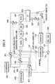
- a fuel reforming system in a first embodiment of the invention is explained by referring to Fig. 2 to Fig. 7 .
- the fuel reforming system of the first embodiment shown in Fig. 2 is characterized in that a temperature sensor 600 is introduced to detect temperature of mixture to be sent into the an autothermal reforming reactor 107 and the output of the temperature sensor 600 is transmitted to a fuel reforming controller 401.
- constituent elements common to those in the prior art in Fig. 1 are identified with same reference numerals.
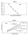
- Fig. 6 shows a dependence of the methanol concentration in the reformed gas supplied from the ATR reactor 107 into the shift reactor 108, on vapor temperature supplied into the ATR reactor 107.
- Fig. 7 shows a dependence of the CO concentration in the reformed gas supplied from the ATR reactor 107 into the shift reactor 108, on vapor temperature supplied into the ATR reactor 107.
- lines 320 and 321 indicate the specification concentrations specifying the upper limit of the methanol and CO concentration in the reformed gas to be supplied from the ATR reactor 107 to the shift reactor 108.
- Curve line 300 in Fig. 6 shows temperature dependence in the autothermal condition, that is, when the POX rate is fixed, and point a is the design point.
- Curve line 301 in Fig. 7 shows temperature dependence in the autothermal condition, that is, when the POX rate is fixed, and point a is the design point.
- point a is the design point.
- the concentration of the methanol and CO discharged from the ATR reactor 107 is in a reverse relation to vapor temperature, that is, in trade-off relation.
- Fig. 6 and Fig. 7 also show results of simulation when the POX rate rpox (%) is corrected as shown in the following numerical formula 2 by using the correction coefficients of POX.
- rate kpox ⁇ 2 ⁇ , ⁇ (%).
- r POX 1 + k POX 100 ⁇ r POX , 0
- operation line 311 is obtained.
- map A shown in Fig. 4 is obtained. Therefore, when the POX rate is corrected depending on vapor temperature by using map A, the concentration of methanol and CO of the reformed gas supplied from the ATR reactor 107 into the shift reactor 108 is the concentration determined by the vapor temperature and the operation lines 310, 311 in Fig. 6 and Fig. 7 .
- the ATR reactor 107 can supply the reformed gas capable of removing the CO in the shift reactor 108 if the vapor temperature varies, and therefore the PROX reactor 109 can supply the reformed gas reduced in the CO concentration so as to be usable in the fuel cell 200.
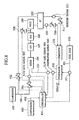
- FIG. 8 A first example, of the invention is explained by referring to Fig. 8 . It is a feature of the first example that the position of the temperature sensor 600 in the first embodiment shown in Fig. 2 is moved onto the piping linking the evaporator 102 and mixer 104. Other constituent elements are same as in the first embodiment. The control sequence and operation of the first example are same as in the first embodiment.
- This example relates to a fuel reforming system in which the change of a gas temperature introduced into the ATR reactor 107 is mainly induced by the change of a vapor temperature supplied in the evaporator 102, and in this system, instead of temperature of the gas introduced into the ATR reactor 107, temperature of the vapor supplied from the evaporator 102 may be detected to control by using a similar map.
- a fuel reforming system in a second embodiment of the invention is explained by referring to Fig. 9 . It is a feature of the second embodiment that the temperature sensor 600 used in the first embodiment in Fig. 2 is moved onto the piping for supplying air into the mixer 104. Therefore, other constituent elements are common to those in the first embodiment. The control sequence and action are also same as in the first embodiment.
- This embodiment relates to a fuel reforming system in which the change of gas temperature introduced into the ATR reactor 107 is mainly induced by the change of air temperature supplied in the ATR reactor 107, and in this system, instead of temperature of the gas introduced into the ATR reactor 107, temperature of the supply air may be detected to control by using a similar map.
- a fuel reforming system in a third embodiment of the invention is explained.
- the configuration of the third embodiment is same as in the first embodiment shown in Fig. 2 , but the control sequence of the fuel reforming controller 401 is different from that of the first embodiment shown in Fig. 3 , which is as shown in Fig. 10 .
- the operation is explained below.
- the POX rate of the design specification (autothermal condition) is, for example, 30%, and its correction rate is in a range of ⁇ 10%
- the POX rate after correction is 27 to 33%. If the change is by such extent, the flow rate of hydrogen in reformed gas is changed only about ⁇ 1%, and the fuel cell 200 discharges about 20% of hydrogen without use to allow to burn in the combustor 110, and therefore the change of the hydrogen flow rate in the obtained reformed gas is within an error range, and no particular measure is needed.
- the first embodiment when the first embodiment is applied in a system in which the POX rate changes significantly, if temperature of the gas introduced into the ATR reactor 107 changes, the methanol concentration and CO concentration in the reformed gas obtained from the ATR reactor 107 can satisfy the specification, but if the correction coefficient of the POX rate is a large positive value, the obtained hydrogen amount decreases, and the power generation required in the fuel cell 200 cannot be produced. To the contrary, in the case of a system with a large negative value of correction coefficient of the POX rate, the hydrogen amount discharged from the fuel cell 200 without being consumed increases, which may lead to drop of system efficiency or overheating of the combustor 110 or evaporator 102.
- the fuel flow rate when the correction coefficient of the POX rate is positive, the fuel flow rate is increased to control so as not to decrease the obtained hydrogen amount, or when the correction coefficient of the POX rate is a large negative value, the fuel flow rate is reduced to control so as not to increase the hydrogen amount, and therefore the hydrogen amount is invariable if the POX rate is changed.
- the POX rate is used as the parameter value for control
- the air flow rate necessary for fuel flow rate is determined from the POX rate
- the POX rate is corrected according to gas temperature introduced into the reformer, but not limited to this mechanism, without using the parameter of POX rate, a map or function of air flow rate necessary for fuel flow rate may be used, and the POX rate may be corrected by gas temperature introduced into the reformer.
- methanol is used as the liquid fuel, but gasoline or other liquid fuel may be used, or gas fuel such as methane may be also applicable depending on the cases.
- liquid fuel methanol and water are stored in a tank, and used as a mixed solution, but they may be stored in different tanks, or instead of one evaporator, two evaporators may be used for evaporating methanol and water independently.
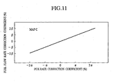
- map C in Fig. 11 a map of linear function of POX rate correction coefficient and fuel flow rate correction coefficient is used, but a map for correcting the fuel flow rate only when exceeding a certain range, without correcting the fuel flow rate as far as the POX rate correction coefficient is within the range, may be used.
- the invention may be similarly applied in fuel reforming reaction using gas containing the oxygen as in the partial oxidation reactor based on partial oxidation reaction.
Landscapes
- Chemical & Material Sciences (AREA)
- Chemical Kinetics & Catalysis (AREA)
- Engineering & Computer Science (AREA)
- Organic Chemistry (AREA)
- Life Sciences & Earth Sciences (AREA)
- Manufacturing & Machinery (AREA)
- Sustainable Development (AREA)
- Sustainable Energy (AREA)
- Electrochemistry (AREA)
- General Chemical & Material Sciences (AREA)
- Combustion & Propulsion (AREA)
- Inorganic Chemistry (AREA)
- General Health & Medical Sciences (AREA)
- Health & Medical Sciences (AREA)
- Hydrogen, Water And Hydrids (AREA)
- Fuel Cell (AREA)
Abstract
Description
- The present invention relates to a fuel reforming device and a fuel reforming method.
- The prior
art document EP 0 798 798 A2 teaches a method of and an apparatus for reforming fuel and the fuel cell system with a fuel reforming apparatus incorporated therein. Said apparatus comprises a reformer for generating a reformed gas containing the hydrogen by using a gas containing vapors of fuel supplied from an evaporator. A methanol tank for storing methanol and a water tank for storing water are connected to said evaporator. An air tank is provided for supplying air to said reformer. The evaporator receives methanol and water from the methanol tank and the water tank, wherein a pump is provided for controlling quantity of methanol supplied to the evaporator and a further pump is provided for controlling quantity of water supplied to the evaporator. A temperature sensor is arranged between the evaporator and a reformer and measures the temperature of the raw fuel gas. The result of the measurement is input as an electric signal into the control unit, wherein the pump for regulating quantities of methanol and water supplied to the evaporator are controlled in consideration of the temperature of the raw fuel gas vaporized in the evaporator and supplied to the reformer. A further temperature sensor is disposed downstream of the reformer and measures the temperature of the gaseous fuel discharged from the reformer. On the basis of said temperature, the related control unit determines the reaction temperature in the reformer and outputs a driving signal to a regulator so as to regulate the amount of air from the air tank to the reformer. - A prior art of a fuel reforming system in a mobile fuel cell system represented by a fuel cell automobile is explained by referring to
Fig. 1 .Amixed solution 101 of water and methanol used as fuel contained in afuel tank 100 is sent into anevaporator 102, and heated and evaporated to form a mixedvapor 103 of water (steam) and methanol, and sent into amixer 104. Air 106 is also sent into themixer 104 from acompressor 105. The mixedsteam 103 andair 106 are mixed in themixer 104, and sent into an autothermal reforming reactor (ATR reactor) 107. - The ATR
reactor 107 reforms the methanol used as fuel by catalytic reaction shown in chemical reaction formulas Chem.1 and Chem.2 by using water and oxygen in air, and produces an oxygen-rich reformed gas.
CH3OH + H2O → CO2 + 3H2 - Q1 (Chem. 1)

- Chemical reaction formula Chem.1 shows steam reaction of methanol (endothermic reaction), and chemical reaction formula Chem.2 denotes partial oxidation reaction of methanol (exothermic reaction). The reaction in chemical reaction formula Chem.1 progresses in steps mainly as shown in chemical reaction formulas Chem.3 and Chem.4.
CH3OH → CO + 2H2 - Q3 (Chem.3)
CO + H2O - CO2 + H2 + Q4 (Chem. 4)
- Chemical reaction formula Chem.3 shows decomposition reaction of methanol (endothermic reaction), and chemical reaction formula Chem. 4 denotes shift reaction of carbon monoxide (exothermic reaction). The ATR
reactor 107 is operated in the autothermal condition for balancing the exothermic and endothermic reactions in these formulas. Therefore, once the size or structure of the reactor, or the performance of the catalyst is determined, the flow rate of steam in relation to the flow rate of the fuel methanol, and the flow rate ratio of air flow rate are almost determined. - The rate of the methanol flow rate consumed for partial oxidation reaction (POX) corresponding to the total methanol flow rate being supplied is defined to be POX rate. Since almost all amount of supplied oxygen is consumed in the partial oxidation reaction (POX) in
formula 2, the air flow rate necessary for the total methanol flow rate is determined from this POX rate. - At the starting time when a catalyst temperature is low, subsidiary reactions given in the following chemical reaction formulas Chem.5 and Chem.6 take place at the same time.
CH3OH → HCHO + H2 (Chem.5)
HCHO → CO + H2 (Chem.6)
- Operating temperature of the ATR
reactor 107 is 300 to 600 °C, and from the thermodynamic chemical equilibrium, reformed gas containing several percent of carbon monoxide is obtained. Carbon monoxide poisons the fuel electrode catalyst composed of platinum and others of solid polymer type fuel cell (FC) 200, and lowers its activity extremely, and therefore it is necessary to decrease the concentration of carbon monoxide to tens of ppm to 100 ppm by a carbon monoxide remover composed of ashift reactor 108 and selective oxidation reactor (PROX reactor) 109, and then supply into thefuel cell 200. - The reformed gas containing several percent of carbon monoxide is sent into the
shift reactor 108, and the carbon monoxide is decreased by the catalyst quick in the shift reaction ofchemical reaction formula 4. Operating temperature of theshift reactor 108 is 200 to 300°C, and from the thermodynamic chemical equilibrium, reformed gas containing several percent of carbon monoxide is obtained. Theshift reactor 108 may be integrated with the ATRreactor 107. The reformed gas decreased in the carbon monoxide by the shift reaction is sent into thePROX reactor 109, and the carbon monoxide is further decreased to tens of ppm to 100 ppm at most by the catalytic oxidation reaction (exothermic reaction) in the followingchemical reaction formula 7. The required oxygen is supplied from thecompressor 105 as air.
- In the
PROX reactor 109, oxidation reaction is performed in steam atmosphere, and the following hydrogen combustion reaction (exothermic reaction) takes place at the same time. Accordingly, the selectivity of chemical reaction formula Chem. 7 on chemical reaction formula Chem. 8 has a serious effect on the efficiency of fuel reforming system.
- The
PROX reactor 109 removes heat generation by chemical reaction formulas Chem.7 and Chem.8, and maintains operating temperature at hundred and tens of degrees centigrade, and therefore it is cooled by air, LLC (coolant), or oil, although not shown in the diagram. - Thus, the reformed gas reduced in carbon dioxide to an extremely low concentration and air from the
compressor 105 are sent into the fuel electrode and air electrode of the fuel cell (FC) 200, and power is generated. - In the
fuel cell 200, it is impossible to use all of the hydrogen contained in the reformed gas, and the reformed gas used in power generation containing a partial residual hydrogen, and the air used in power generation containing a partial residual oxygen are sent into acatalytic combustor 110, and burn. The obtained high temperature exhaust gas is sent into theevaporator 102, and recycled as evaporation energy of methanol and water. -
Reference numeral 500 is a flow rate control valve for controlling the flow rate of the air supplied into the PROX reactor, 109, 501 is a flow rate control valve for controlling the flow rate of the air supplied into the ATRreactor fuel cell 200.Reference numeral 510 is a pressure control valve for adjusting the operating pressure of the fuel electrode of thefuel cell fuel cell 200.Reference numerals fuel cell 200, and the pressure is adjusted so that the pressures of these may be equal. -
Reference numeral 400 is a controller for mobile energy management, and it sends anoperation load signal 402 of the fuel reforming system to afuel cell controller 401. Thefuel cell controller 401, on the basis of theoperation load signal 402, drives apump 111 so as to achieve the flow rate of fuel vapor and air necessary for the ATRreactor 107, and controls the flow rate of the liquid fuel to be supplied into theevaporator 102 and controls the flowrate control valve 501.Reference numerals - As the
evaporator 102, if a huge evaporator capable of controlling temperature of the generated vapor thereof is used, or if an evaporator of an extremely large thermal capacity or heating area is operated at a constant temperature, vapor temperature supplied from theevaporator 102 into theATR reactor 107 can be kept substantially constant. - Such evaporator may be used in a fuel reforming system for a stationary fuel cell, but the fuel reforming system for mobile fuel cell is limited in space and such evaporator cannot be installed, and the
evaporator 102 of compact and simple structure have to be used. - However, when using
such evaporator 102, vapor temperature generated from theevaporator 102 may vary significantly depending on the operating situation of the fuel reforming system in temperature range from a low temperature near the boiling point to a high temperature of exhaust gas temperature supplied from thecombustor 110 into the evaporator. As a result, if vapor temperature supplied in the ATRreactor 107 becomes higher than the design specification, the CO concentration in the reformed gas supplied from the ATRreactor 107 into theshift reactor 108 becomes higher than the specification, and the CO concentration supplied from theshift reactor 108 to thePROX reactor 109 becomes high, and hence the CO concentration of the reformed gas supplied from thePROX reactor 109 into thefuel cell 200 may exceed the allowable value for the fuel cell. - To the contrary, if a vapor temperature supplied from the ATR
reactor 107 becomes lower than the design specification, the residual methanol concentration in the reformed gas as supplied from theATR reactor 107 into theshift reactor 108 becomes higher than the specification, and when removing the CO in theshift reactor 108 andPROX reactor 109, the methanol must be treated in the first place, and the CO is not removed sufficiently, and therefore the CO concentration of the reformed gas supplied from thePROX reactor 109 into thefuel cell 200 exceeds the allowable value for the fuel cell. - Still more, the increase of unreacted methanol components may induce decline of power generation performance depending on the type of the electrode catalyst or hydrogen ion filtration membrane used in the
fuel cell 200. - Therefore, in the conventional fuel reforming system for mobile fuel cell system, since a vapor temperature supplied from the evaporator into the ATR reactor changes significantly, the reformed gas composition supplied from the ATR reactor into the CO remover is out of the composition specification that can be treated by the CO remover, and the composition of the reformed gas to be supplied from the fuel reforming system into the fuel cell stack may be out of the original specification composition. Or, when an evaporator capable of controlling temperature of the vapor is used, the evaporator is increased in size and is hence difficult to install, and the cost is raised as well.
- It is the object of the present invention to provide a fuel reforming device and a fuel reforming method for a mobile fuel cell system which is capable of obtaining a reformed gas composition usable in the fuel cell even if a vapor temperature supplied from the evaporator into the fuel reformer varies significantly.
- According to the apparatus aspect of the present invention, said objective is solved by a fuel reforming device having the features of
independent claim 1. A preferred embodiment is laid down in the dependent claim. - Moreover, according to the method aspect of the present invention, said objective is also solved by a fuel reforming method having the features of
independent claim 3. Preferred embodiments are laid down in the dependent claims. - Accordingly, it is provided a fuel reforming system with
means fuel reformer 107, and means 600 for detecting temperature of at least one of fuel vapor to be supplied into the fuel reformer, temperature of oxygen, and temperature of mixed gas of fuel vapor and oxygen, in which a ratio of the flow rate of fuel vapor to the flow rate of oxygen is corrected on the basis of the signal value of the temperature detecting means, and the oxygen is supplied depending on the corrected ratio. - In other words, a fuel reforming method of a fuel reforming system is characterized in that, the fuel reforming system having a fuel reformer for generating a reformed gas containing the hydrogen by using a gas containing vapors of a gas fuel or a liquid fuel and the oxygen, mixer of vapors of a gas fuel or a liquid fuel and a gas containing the hydrogen, first supplier of vapor of a gas fuel or a liquid fuel into the fuel reformer through the mixer, and second supplier of a gas containing the oxygen into the fuel reformer through the mixer, provided with supplying the liquid fuel into the first supplier; detecting temperature of the vapor of the gas fuel or the liquid fuel supplied into the fuel reformer; determining first correction coefficient of a ratio of first flow rate of the vapors of the gas fuel to second flow rate of the gas containing the oxygen according to the detected temperature; detecting the first flow rate of the vapors; determining the second flow rate to be supplied to the second supplier according to the detected first flow rate and the determined first correction coefficient; adjusting flow rate of the gas containing the oxygen into the fuel reformer by controlling the second supplier according to the determined second flow rate.
-
-
Fig. 1 is a block diagram of a prior art; -
Fig. 2 is a block diagram of a first embodiment of the invention; -
Fig. 3 is a control sequence diagramof the first embodiment; -
Fig. 4 is a graph of map A (POX rate correction coefficient in relation to vapor temperature) used in the first embodiment; -
Fig. 5 is a graph of map B (air flow rate in relation to vapor flow rate) used in the first embodiment; -
Fig. 6 is a graph showing the dependence of methanol concentration in the exhaust reformed gas of the ATR reactor on vapor temperature supplied into the ATR reactor in the first embodiment, in which points a to e correspond to the points inFig. 4 ; -
Fig. 7 is a graph showing the dependence of CO concentration in exhaust reformed gas of the ATR reactor on the vapor temperature supplied into the ATR reactor in the first embodiment, in which points a to e correspond to the points inFig. 6 ; -
Fig. 8 is a block diagram of a first example, which does net form part of the invention; -
Fig. 9 is a block diagram of a second embodiment of the invention; -
Fig. 10 is a control sequence diagram in a third embodiment of the invention; -
Fig. 11 is a graph of map C (fuel flow rate correction coefficient in relation to POX rate correction coefficient) used in the third embodiment. - A fuel reforming system in a first embodiment of the invention is explained by referring to
Fig. 2 to Fig. 7 . The fuel reforming system of the first embodiment shown inFig. 2 is characterized in that atemperature sensor 600 is introduced to detect temperature of mixture to be sent into the anautothermal reforming reactor 107 and the output of thetemperature sensor 600 is transmitted to afuel reforming controller 401. InFig. 2 , constituent elements common to those in the prior art inFig. 1 are identified with same reference numerals. - The control sequence by the
fuel reforming controller 401 of this fuel reforming system is explained by referring toFig. 3 . - Step 1: The
fuel reforming controller 401 reads in anoperation load signal 402 of the fuel reforming system sent from thecontroller 400. - Step 2: The
fuel reforming controller 401 controls thepump 111 on the basis of theoperation load signal 402, and supplies a necessary flow rate of liquid fuel into theevaporator 102. - Step 3: The
fuel reforming controller 401 reads in a signal value of vapor temperature from thetemperature sensor 600. - Step 4: The
fuel reforming controller 401 determines the correction coefficient kpox (%) of the POX rate by using map A shown inFig. 4 , from the signal value of vapor temperature of thetemperature sensor 600. - Step 5: A signal value of vapor flow rate of fuel is read in from the
flow rate sensor 601. - Step 6: From the signal value of the fuel vapor flow rate being read at
step 5, and the correction coefficient kpox (%) of the POX rate determined atstep 4, the air flow rate to be supplied is determined by using map B shown inFig. 5 . This map B is a graphic expression of thefollowing conversion formula 1.
In the formula, rPOX,0 is approximately 30(%) in near autothermal condition. - Step 7: The valve opening degree of the flow
rate control valve 501 is adjusted so as to set at the air flow rate determined atstep 6. - In this control sequence, depending on the vapor flow rate from the
evaporator 102 and vapor temperature supplied from themixer 104, the fuel is supplied into theATR reactor 107 while the air flow rate is always controlled to be the POX rate corrected by map A. - In the fuel reforming system of the first embodiment, the operation is explained below.
Fig. 6 shows a dependence of the methanol concentration in the reformed gas supplied from theATR reactor 107 into theshift reactor 108, on vapor temperature supplied into theATR reactor 107. Similarly,Fig. 7 shows a dependence of the CO concentration in the reformed gas supplied from theATR reactor 107 into theshift reactor 108, on vapor temperature supplied into theATR reactor 107. These are the results of simulation of the series of chemical reaction formulas mentioned in the explanation of the prior art, by using the chemical reaction rate in the catalyst used in theATR reactor 107. - In
Fig. 6 andFig. 7 ,lines 320 and 321 indicate the specification concentrations specifying the upper limit of the methanol and CO concentration in the reformed gas to be supplied from theATR reactor 107 to theshift reactor 108. -
Curve line 300 inFig. 6 shows temperature dependence in the autothermal condition, that is, when the POX rate is fixed, and point a is the design point. When vapor temperature hikes, the methanol concentration declines, and hence there is no problem, but when vapor temperature drops, the methanol concentration elevates, possibly failing to satisfy the specification of the methanol concentration of the reformed gas to be supplied into theshift reactor 108. -
Curve line 301 inFig. 7 shows temperature dependence in the autothermal condition, that is, when the POX rate is fixed, and point a is the design point. When vapor temperature is lowered, the CO concentration descends, and there is no problem, but when vapor temperature rises, the CO concentration climbs up, possibly failing to satisfy the specification of the CO concentration of the reformed gas to be supplied into theshift reactor 108. - The concentration of the methanol and CO discharged from the
ATR reactor 107 is in a reverse relation to vapor temperature, that is, in trade-off relation. - Meanwhile,
Fig. 6 andFig. 7 also show results of simulation when the POX rate rpox (%) is corrected as shown in the followingnumerical formula 2 by using the correction coefficients of POX. rate kpox = ±2α, ±α(%).
- It is known from here that the methanol concentration is lowered and the CO concentration rises up when corrected so as to increase the POX rate rpox (%), and, to the contrary, when corrected to decrease the POX rate rpox (%), the methanol concentration ascends and the CO concentration descends.
- By drawing an
operation line 310 in a region of concentration below the specification concentration specified by line 320 inFig. 6 , when the POX rate is determined at points c, b, d, e on theoperation line 310 at each vapor temperature and the CO concentration at each point is plotted inFig. 7 ,operation line 311 is obtained. - When points on the obtained
operation lines Fig. 4 is obtained. Therefore, when the POX rate is corrected depending on vapor temperature by using map A, the concentration of methanol and CO of the reformed gas supplied from theATR reactor 107 into theshift reactor 108 is the concentration determined by the vapor temperature and the operation lines 310, 311 inFig. 6 andFig. 7 . As a result, if the vapor temperature fluctuates, it is below the concentration of thespecification concentration 320, 321, and theATR reactor 107 can supply the reformed gas capable of removing the CO in theshift reactor 108 if the vapor temperature varies, and therefore thePROX reactor 109 can supply the reformed gas reduced in the CO concentration so as to be usable in thefuel cell 200. - A first example, of the invention is explained by referring to
Fig. 8 . It is a feature of the first example that the position of thetemperature sensor 600 in the first embodiment shown inFig. 2 is moved onto the piping linking theevaporator 102 andmixer 104. Other constituent elements are same as in the first embodiment. The control sequence and operation of the first example are same as in the first embodiment. - This example relates to a fuel reforming system in which the change of a gas temperature introduced into the
ATR reactor 107 is mainly induced by the change of a vapor temperature supplied in theevaporator 102, and in this system, instead of temperature of the gas introduced into theATR reactor 107, temperature of the vapor supplied from theevaporator 102 may be detected to control by using a similar map. - A fuel reforming system in a second embodiment of the invention is explained by referring to
Fig. 9 . It is a feature of the second embodiment that thetemperature sensor 600 used in the first embodiment inFig. 2 is moved onto the piping for supplying air into themixer 104. Therefore, other constituent elements are common to those in the first embodiment. The control sequence and action are also same as in the first embodiment. - This embodiment relates to a fuel reforming system in which the change of gas temperature introduced into the
ATR reactor 107 is mainly induced by the change of air temperature supplied in theATR reactor 107, and in this system, instead of temperature of the gas introduced into theATR reactor 107, temperature of the supply air may be detected to control by using a similar map. - A fuel reforming system in a third embodiment of the invention is explained. The configuration of the third embodiment is same as in the first embodiment shown in
Fig. 2 , but the control sequence of thefuel reforming controller 401 is different from that of the first embodiment shown inFig. 3 , which is as shown inFig. 10 . - The control sequence of the
fuel reforming controller 401 in the fuel reforming system of the third embodiment is explained by referring toFig. 10 . - Step 11: The
fuel reforming controller 401 reads in anoperation load signal 402 of the fuel reforming system sent from thecontroller 400. - Step 12: From the
operation load signal 402 and the fuel flow rate correction coefficient kFuel (%) of the fuel supplied into theevaporator 102 stored in the memory, the required fuel flow rate Ffuel,liq is determined in the followingnumerical formula 3.
- Step 13: A required flow rate of liquid fuel Ffuel,liq is supplied into the
evaporator 102. - Step 14: The signal value of vapor temperature of the
temperature sensor 600 is read in. - Steep 15: From the signal value of vapor temperature of the
temperature sensor 600, the correction coefficient kpox (%) of POX rate is determined by using map A inFig. 4 . - Step 16: The signal value of the vapor flow rte of the fuel of the
flow rate sensor 601 is read in. - Step 17: From the signal value of the vapor flow rate of the fuel and the correction coefficient kpox (%) of the POX rate determined at
step 15, the air flow rate to be supplied is determined by using map B inFig. 5 . - Step 18: The opening degree of the flow
rate control valve 501 is adjusted so as to conform to the air flow rate determined atstep 16. - Step 19: Using map C shown in
Fig. 11 , from the correction coefficient kpox (%) of the POX rate determined atstep 15, the fuel flow rate correction coefficient kFuel (%) of the fuel supplied into theevaporator 102 is determined and set in the memory. Herein, if the correction coefficient kpox (%) of the POX rate is 3%, the value of the fuel flow rate correction coefficient kFuel (%) is about 1%. The initial value of the memory is 0. - In the fuel reforming system of the third embodiment, the operation is explained below. In the foregoing first embodiment, if the POX rate of the design specification (autothermal condition) is, for example, 30%, and its correction rate is in a range of ±10%, the POX rate after correction is 27 to 33%. If the change is by such extent, the flow rate of hydrogen in reformed gas is changed only about ±1%, and the
fuel cell 200 discharges about 20% of hydrogen without use to allow to burn in thecombustor 110, and therefore the change of the hydrogen flow rate in the obtained reformed gas is within an error range, and no particular measure is needed. However, when the first embodiment is applied in a system in which the POX rate changes significantly, if temperature of the gas introduced into theATR reactor 107 changes, the methanol concentration and CO concentration in the reformed gas obtained from theATR reactor 107 can satisfy the specification, but if the correction coefficient of the POX rate is a large positive value, the obtained hydrogen amount decreases, and the power generation required in thefuel cell 200 cannot be produced. To the contrary, in the case of a system with a large negative value of correction coefficient of the POX rate, the hydrogen amount discharged from thefuel cell 200 without being consumed increases, which may lead to drop of system efficiency or overheating of thecombustor 110 orevaporator 102. - By contrast, in the third embodiment, when the correction coefficient of the POX rate is positive, the fuel flow rate is increased to control so as not to decrease the obtained hydrogen amount, or when the correction coefficient of the POX rate is a large negative value, the fuel flow rate is reduced to control so as not to increase the hydrogen amount, and therefore the hydrogen amount is invariable if the POX rate is changed.
- The embodiments are explained by referring to specific drawings, but the invention is not limited to such description and illustration alone. Other examples are presented below.
- In the foregoing embodiments, the POX rate is used as the parameter value for control, the air flow rate necessary for fuel flow rate is determined from the POX rate, and the POX rate is corrected according to gas temperature introduced into the reformer, but not limited to this mechanism, without using the parameter of POX rate, a map or function of air flow rate necessary for fuel flow rate may be used, and the POX rate may be corrected by gas temperature introduced into the reformer.
- Herein, methanol is used as the liquid fuel, but gasoline or other liquid fuel may be used, or gas fuel such as methane may be also applicable depending on the cases.
- The liquid fuel methanol and water are stored in a tank, and used as a mixed solution, but they may be stored in different tanks, or instead of one evaporator, two evaporators may be used for evaporating methanol and water independently.
- As map C in
Fig. 11 , a map of linear function of POX rate correction coefficient and fuel flow rate correction coefficient is used, but a map for correcting the fuel flow rate only when exceeding a certain range, without correcting the fuel flow rate as far as the POX rate correction coefficient is within the range, may be used. - As the fuel reformer, an example of autothermal reactor is used, but the invention may be similarly applied in fuel reforming reaction using gas containing the oxygen as in the partial oxidation reactor based on partial oxidation reaction.
Claims (5)
- A fuel reforming device comprising:a fuel reformer (107) for generating a reformed gas containing the hydrogen by using a gas containing vapors of a gas fuel or vapors of a liquid fuel and the oxygen,a mixer (104) for mixing of vapors of the gas fuel or vapors of the liquid fuel and a gas containing the oxygen,a supplier (100, 101, 102, 103, 111) for supplying of vapors of the gas fuel or vapors of the liquid fuel into said fuel reformer (107) through the mixer (104),a supplier (105, 106) for supplying of the gas containing the oxygen into said fuel reformer (107) through the mixer (104) anda detector (601) for detecting of the first flow rate of the vapors of the gas fuel or vapors of the liquid fuel;a detector (602) for detecting of the second flow rate of the gas containing the oxygen; and a controller (401 connected to the detectors (601, 602) for controlling of first flow rate of the vapors of the gas fuel or vapors of the liquid fuel supplied into said fuel reformer (107) and for controlling of second flow rate of the gas containing the oxygen supplied into said fuel reformer (107),a temperature detector (600) for detecting temperature of at least one of the gas containing the oxygen supplied into said fuel reformer (107), and of the mixture of vapors of the gas fuel or vapors of the liquid fuel and the gas containing the oxygen,wherein said controller (401) is adapted for correcting a ratio of the first flow rate of the vapors of the gas fuel or vapors of the liquid fuel to the second flow rate of the gas containing the oxygen depending on the output of said temperature detector (600), and adapted for controlling supply of the gas containing the oxygen depending on the corrected ratio.
- A fuel reforming device according to claim 1, wherein said controller (401) is adapted for correcting and controlling supply of a flow rate of the gas fuel, a flow rate of the vapor of the liquid fuel, or a flow rate of the liquid fuel depending on a correction value of the ratio of the flow rate of vapors of the gas fuel or vapors of the liquid fuel to the flow rate of the gas containing the oxygen.
- A fuel reforming method of fuel reforming device according to claim 1 comprising a fuel reformer (107) for generating a reformed gas containing the hydrogen by using a gas containing vapors of a gas fuel or vapors of a liquid fuel and the oxygen and a mixer (104) for mixing of vapors of the gas fuel or vapors of the liquid fuel and a gas containing the oxygen, said method comprises the steps of:supplying of vapors of the gas fuel or vapors of the liquid fuel into said fuel reformer (107) through the mixer (104),supplying of the gas containing the oxygen into said fuel reformer (107) through the mixer (104), andcontrolling of first flow rate of the vapors of the gas fuel or vapors of the liquid fuel supplied into said fuel reformer (107) and controlling of second flow rate of the gas containing the oxygen supplied into said fuel reformer (107),detecting of the first flow rate of the vapors of the gas fuel or vapors of the liquid fuel;detecting of the second flow rate of the gas containing the oxygen; anddetecting temperature of at least one of the gas containing the oxygen supplied into said fuel reformer (107), and of the mixture of vapors of the gas fuel or vapors of the liquid fuel and the gas containing the oxygen, andcorrecting a ratio of the first flow rate of the vapors of the gas fuel or vapors of the liquid fuel to the second flow rate of the gas containing the oxygen depending on said temperature, and the gas containing the oxygen is supplied depending on the corrected ratio.
- A fuel reforming method of fuel reforming device according to claim 3, further comprising:determining first correction coefficient of the ratio of first flow rate of the vapors of the gas fuel or vapors of the liquid fuel to second flow rate of the gas containing the oxygen according to the detected temperature.
- A fuel reforming method of fuel reforming device according to claim 4, wherein prior to supplying the liquid fuel, determining a required flow rate of the liquid fuel to be supplied to a supplier for supplying vapors of the liquid fuel of vapors according to a memorized fuel flow rate correction coefficient; and after adjusting flow rate of the gas containing the oxygen, determining the fuel flow rate correction coefficient according to the determined first correction coefficient.
Applications Claiming Priority (3)
| Application Number | Priority Date | Filing Date | Title |
|---|---|---|---|
| JP2000164646 | 2000-06-01 | ||
| JP2000164646A JP3678118B2 (en) | 2000-06-01 | 2000-06-01 | Fuel reforming system |
| PCT/JP2001/003832 WO2001092147A1 (en) | 2000-06-01 | 2001-05-08 | Fuel reforming system |
Publications (2)
| Publication Number | Publication Date |
|---|---|
| EP1289878A1 EP1289878A1 (en) | 2003-03-12 |
| EP1289878B1 true EP1289878B1 (en) | 2012-08-08 |
Family
ID=18668237
Family Applications (1)
| Application Number | Title | Priority Date | Filing Date |
|---|---|---|---|
| EP01926145A Expired - Lifetime EP1289878B1 (en) | 2000-06-01 | 2001-05-08 | Fuel reforming system |
Country Status (6)
| Country | Link |
|---|---|
| US (1) | US7189371B2 (en) |
| EP (1) | EP1289878B1 (en) |
| JP (1) | JP3678118B2 (en) |
| KR (1) | KR100466381B1 (en) |
| CN (1) | CN1329287C (en) |
| WO (1) | WO2001092147A1 (en) |
Families Citing this family (35)
| Publication number | Priority date | Publication date | Assignee | Title |
|---|---|---|---|---|
| JP4245298B2 (en) * | 2002-02-27 | 2009-03-25 | ダイセル化学工業株式会社 | Gas reaction component supply control method and control apparatus |
| AU2002315685A1 (en) * | 2002-04-11 | 2003-10-27 | Webasto Thermosysteme Gmbh | Method and device for controlling a reformer for fuel cells |
| JP4363002B2 (en) | 2002-04-18 | 2009-11-11 | 日産自動車株式会社 | Fuel reforming system and its warm-up device |
| JP2004018363A (en) * | 2002-06-20 | 2004-01-22 | Nissan Motor Co Ltd | Apparatus for fuel reforming |
| DE10231126A1 (en) * | 2002-07-10 | 2004-02-05 | Daimlerchrysler Ag | Process for starting a gas generating system |
| US7014835B2 (en) * | 2002-08-15 | 2006-03-21 | Velocys, Inc. | Multi-stream microchannel device |
| US6969505B2 (en) * | 2002-08-15 | 2005-11-29 | Velocys, Inc. | Process for conducting an equilibrium limited chemical reaction in a single stage process channel |
| US6622519B1 (en) * | 2002-08-15 | 2003-09-23 | Velocys, Inc. | Process for cooling a product in a heat exchanger employing microchannels for the flow of refrigerant and product |
| KR100533298B1 (en) * | 2002-09-30 | 2005-12-05 | 가부시끼가이샤 도시바 | Fuel cell system |
| AU2003287307A1 (en) * | 2002-10-30 | 2004-06-07 | Nuvera Fuel Cells, Inc. | Method and system for controlling fluid flow in a fuel processing system |
| US6745801B1 (en) | 2003-03-25 | 2004-06-08 | Air Products And Chemicals, Inc. | Mobile hydrogen generation and supply system |
| CN100395012C (en) * | 2003-12-09 | 2008-06-18 | 松下电器产业株式会社 | Hydrogen generating apparatus |
| US8747805B2 (en) | 2004-02-11 | 2014-06-10 | Velocys, Inc. | Process for conducting an equilibrium limited chemical reaction using microchannel technology |
| KR101126201B1 (en) | 2004-06-23 | 2012-03-28 | 삼성에스디아이 주식회사 | Fuel cell system and reformer used thereto |
| KR100627334B1 (en) * | 2004-06-29 | 2006-09-25 | 삼성에스디아이 주식회사 | Reformer for fuel cell system and fuel cell system comprising the same |
| US7645532B2 (en) * | 2004-08-02 | 2010-01-12 | Delphi Technologies, Inc. | Solid-oxide fuel cell system having an upstream reformate combustor |
| US7468092B2 (en) | 2004-09-17 | 2008-12-23 | Air Products And Chemicals, Inc. | Operation of mixed conducting metal oxide membrane systems under transient conditions |
| US7311755B2 (en) | 2004-09-17 | 2007-12-25 | Air Products And Chemicals, Inc. | Control of differential strain during heating and cooling of mixed conducting metal oxide membranes |
| GB0612092D0 (en) * | 2006-06-20 | 2006-07-26 | Johnson Matthey Plc | Oxygen removal |
| US7905259B2 (en) * | 2006-11-15 | 2011-03-15 | Honeywell International Inc. | Advanced carbon dioxide fuel tank inerting system |
| KR100998918B1 (en) * | 2008-05-29 | 2010-12-08 | 제주대학교 산학협력단 | Apparatus and method for reforming |
| US9178235B2 (en) * | 2009-09-04 | 2015-11-03 | Lg Fuel Cell Systems, Inc. | Reducing gas generators and methods for generating a reducing gas |
| US9140220B2 (en) | 2011-06-30 | 2015-09-22 | Lg Fuel Cell Systems Inc. | Engine systems and methods of operating an engine |
| US9118048B2 (en) | 2009-09-04 | 2015-08-25 | Lg Fuel Cell Systems Inc. | Engine systems and methods of operating an engine |
| WO2011118158A1 (en) * | 2010-03-23 | 2011-09-29 | パナソニック株式会社 | Fuel cell system and control system for same |
| US9116528B2 (en) | 2011-04-26 | 2015-08-25 | Panasonic Intellectual Property Management Co., Ltd. | Hydrogen generation apparatus, fuel cell system, and method of operating the same |
| US10106406B2 (en) | 2013-11-06 | 2018-10-23 | Watt Fuel Cell Corp. | Chemical reactor with manifold for management of a flow of gaseous reaction medium thereto |
| US9627700B2 (en) | 2013-11-06 | 2017-04-18 | Watt Fuel Cell Corp. | Liquid fuel CPOX reformer and fuel cell systems, and methods of producing electricity |
| MX2016004622A (en) | 2013-11-06 | 2016-08-01 | WATT Fuel Cell Corp | Integrated gaseous fuel cpox reformer and fuel cell systems, and methods of producing electricity. |
| CA2929136C (en) | 2013-11-06 | 2018-03-13 | Watt Fuel Cell Corp. | Reformer with perovskite as structural component thereof |
| JP6231697B2 (en) | 2013-11-06 | 2017-11-15 | ワット・フューエル・セル・コーポレイションWatt Fuel Cell Corp. | Liquid fuel CPOX reformer and CPOX reforming method |
| MX352220B (en) | 2013-11-06 | 2017-11-15 | WATT Fuel Cell Corp | Gaseous fuel cpox reformers and methods of cpox reforming. |
| AU2015305815A1 (en) * | 2014-08-19 | 2017-02-23 | WATT Fuel Cell Corp | Multi-reformable fuel delivery systems and methods for fuel cells |
| CN110661019B (en) * | 2019-09-30 | 2022-05-06 | 西安新衡科测控技术有限责任公司 | Control system and method for oxygen supply fan of HT-PEM methanol-water fuel cell combustion chamber |
| WO2022245880A2 (en) * | 2021-05-18 | 2022-11-24 | Obantarla Corp. | Autonomous modular flare gas conversion systems and methods |
Citations (1)
| Publication number | Priority date | Publication date | Assignee | Title |
|---|---|---|---|---|
| EP0798798A2 (en) * | 1996-03-26 | 1997-10-01 | Toyota Jidosha Kabushiki Kaisha | Method of and apparatus for refroming fuel and fuel cell system with fuel-reforming apparatus incorporated therein |
Family Cites Families (9)
| Publication number | Priority date | Publication date | Assignee | Title |
|---|---|---|---|---|
| JPS5849588B2 (en) | 1978-08-18 | 1983-11-05 | 大分瓦斯株式会社 | Temperature control method for partial combustion gas reformer |
| JP2689638B2 (en) * | 1988-10-07 | 1997-12-10 | 富士電機株式会社 | Reforming catalyst temperature control method and apparatus |
| JPH07296834A (en) | 1994-04-26 | 1995-11-10 | Hitachi Ltd | Fuel cell power plant and operating method for reformer of plant |
| US6630109B2 (en) * | 1998-07-16 | 2003-10-07 | Toyota Jidosha Kabushiki Kaisha | Control apparatus for reformer and method of controlling reformer using control apparatus |
| JP4164901B2 (en) | 1998-07-16 | 2008-10-15 | トヨタ自動車株式会社 | Control device for reformer |
| JP2000034102A (en) | 1998-07-17 | 2000-02-02 | Toyota Motor Corp | Controller of reformer |
| JP4192301B2 (en) | 1998-08-03 | 2008-12-10 | トヨタ自動車株式会社 | Control device for reformer |
| WO2001016022A1 (en) * | 1999-08-31 | 2001-03-08 | Shell Internationale Research Maatschappij B.V. | Catalytic oxidation process with flow control system |
| US20010046462A1 (en) * | 2000-04-05 | 2001-11-29 | Richard Woods | Pulsed flow fuel processing system |
-
2000
- 2000-06-01 JP JP2000164646A patent/JP3678118B2/en not_active Expired - Fee Related
-
2001
- 2001-05-08 US US10/048,023 patent/US7189371B2/en not_active Expired - Lifetime
- 2001-05-08 KR KR20027001429A patent/KR100466381B1/en active IP Right Grant
- 2001-05-08 CN CNB018015786A patent/CN1329287C/en not_active Expired - Lifetime
- 2001-05-08 EP EP01926145A patent/EP1289878B1/en not_active Expired - Lifetime
- 2001-05-08 WO PCT/JP2001/003832 patent/WO2001092147A1/en active IP Right Grant
Patent Citations (1)
| Publication number | Priority date | Publication date | Assignee | Title |
|---|---|---|---|---|
| EP0798798A2 (en) * | 1996-03-26 | 1997-10-01 | Toyota Jidosha Kabushiki Kaisha | Method of and apparatus for refroming fuel and fuel cell system with fuel-reforming apparatus incorporated therein |
Also Published As
| Publication number | Publication date |
|---|---|
| WO2001092147A1 (en) | 2001-12-06 |
| CN1383417A (en) | 2002-12-04 |
| US7189371B2 (en) | 2007-03-13 |
| CN1329287C (en) | 2007-08-01 |
| KR20020048382A (en) | 2002-06-22 |
| EP1289878A1 (en) | 2003-03-12 |
| JP2001348202A (en) | 2001-12-18 |
| JP3678118B2 (en) | 2005-08-03 |
| US20020131907A1 (en) | 2002-09-19 |
| KR100466381B1 (en) | 2005-01-13 |
Similar Documents
| Publication | Publication Date | Title |
|---|---|---|
| EP1289878B1 (en) | Fuel reforming system | |
| US6841280B2 (en) | Fuel cell power plant | |
| US7452391B2 (en) | Feedforward control processes for variable output hydrogen generators | |
| WO1996006387A1 (en) | Method and apparatus for the oxidation of carbon monoxide | |
| JP5037214B2 (en) | Reformer system, fuel cell system, and operation method thereof | |
| US6884533B2 (en) | Utilization based power plant control system | |
| US6635371B2 (en) | Fuel cell system | |
| WO2006009153A1 (en) | Hydrogen formation apparatus and method for operation thereof, and fuel cell system | |
| US6455008B1 (en) | Fuel reformer and fuel reforming method | |
| WO2012091035A1 (en) | Fuel cell system | |
| JP2005272598A (en) | Fuel gas production system and method for starting-up the same | |
| WO2005018035A1 (en) | Fuel cell power generation system, method of detecting deterioration degree of reformer for the system, and fuel cell power generation method | |
| JP2009084135A (en) | Fuel processor, driving method therefor, and fuel cell system | |
| JP2005235583A (en) | Fuel cell system and its control method | |
| JP2006027965A (en) | Hydrogen generator and fuel cell power generation system | |
| JP2009076392A (en) | Liquid fuel cell power generation system | |
| JP4612322B2 (en) | Fuel gas production system and operation method thereof | |
| JP4610097B2 (en) | Fuel reforming system | |
| JP7108832B2 (en) | Hydrogen generator, fuel cell system using the same, and method of operating the same | |
| US7258704B2 (en) | Hydrogen generator and fuel cell system having the same | |
| US7717970B2 (en) | Fuel reforming device | |
| JP2001180906A (en) | Hydrogen producing equipment | |
| JP4988259B2 (en) | Fuel cell system | |
| JP2008137866A (en) | Fuel processor and its operation control method | |
| JP2004296383A (en) | Operation control system for carbon monoxide remover, and operation control system for fuel cell system |
Legal Events
| Date | Code | Title | Description |
|---|---|---|---|
| PUAI | Public reference made under article 153(3) epc to a published international application that has entered the european phase |
Free format text: ORIGINAL CODE: 0009012 |
|
| 17P | Request for examination filed |
Effective date: 20020131 |
|
| AK | Designated contracting states |
Kind code of ref document: A1 Designated state(s): DE FR GB |
|
| 17Q | First examination report despatched |
Effective date: 20100416 |
|
| GRAP | Despatch of communication of intention to grant a patent |
Free format text: ORIGINAL CODE: EPIDOSNIGR1 |
|
| RIC1 | Information provided on ipc code assigned before grant |
Ipc: C01B 3/32 20060101AFI20120203BHEP Ipc: B01J 19/00 20060101ALI20120203BHEP Ipc: H01M 8/06 20060101ALI20120203BHEP Ipc: B01B 1/00 20060101ALI20120203BHEP Ipc: C01B 3/48 20060101ALI20120203BHEP Ipc: H01M 8/04 20060101ALI20120203BHEP Ipc: C01B 3/58 20060101ALI20120203BHEP Ipc: B01J 8/00 20060101ALI20120203BHEP |
|
| GRAS | Grant fee paid |
Free format text: ORIGINAL CODE: EPIDOSNIGR3 |
|
| GRAA | (expected) grant |
Free format text: ORIGINAL CODE: 0009210 |
|
| AK | Designated contracting states |
Kind code of ref document: B1 Designated state(s): DE FR GB |
|
| REG | Reference to a national code |
Ref country code: GB Ref legal event code: FG4D |
|
| REG | Reference to a national code |
Ref country code: DE Ref legal event code: R096 Ref document number: 60146956 Country of ref document: DE Effective date: 20121011 |
|
| PLBE | No opposition filed within time limit |
Free format text: ORIGINAL CODE: 0009261 |
|
| STAA | Information on the status of an ep patent application or granted ep patent |
Free format text: STATUS: NO OPPOSITION FILED WITHIN TIME LIMIT |
|
| 26N | No opposition filed |
Effective date: 20130510 |
|
| REG | Reference to a national code |
Ref country code: DE Ref legal event code: R097 Ref document number: 60146956 Country of ref document: DE Effective date: 20130510 |
|
| REG | Reference to a national code |
Ref country code: FR Ref legal event code: PLFP Year of fee payment: 16 |
|
| REG | Reference to a national code |
Ref country code: FR Ref legal event code: PLFP Year of fee payment: 17 |
|
| REG | Reference to a national code |
Ref country code: FR Ref legal event code: PLFP Year of fee payment: 18 |
|
| PGFP | Annual fee paid to national office [announced via postgrant information from national office to epo] |
Ref country code: DE Payment date: 20200428 Year of fee payment: 20 Ref country code: FR Payment date: 20200414 Year of fee payment: 20 |
|
| PGFP | Annual fee paid to national office [announced via postgrant information from national office to epo] |
Ref country code: GB Payment date: 20200429 Year of fee payment: 20 |
|
| REG | Reference to a national code |
Ref country code: DE Ref legal event code: R071 Ref document number: 60146956 Country of ref document: DE |
|
| REG | Reference to a national code |
Ref country code: GB Ref legal event code: PE20 Expiry date: 20210507 |
|
| PG25 | Lapsed in a contracting state [announced via postgrant information from national office to epo] |
Ref country code: GB Free format text: LAPSE BECAUSE OF EXPIRATION OF PROTECTION Effective date: 20210507 |