EP1289864B1 - Shuttle top diverter - Google Patents
Shuttle top diverter Download PDFInfo
- Publication number
- EP1289864B1 EP1289864B1 EP01964980A EP01964980A EP1289864B1 EP 1289864 B1 EP1289864 B1 EP 1289864B1 EP 01964980 A EP01964980 A EP 01964980A EP 01964980 A EP01964980 A EP 01964980A EP 1289864 B1 EP1289864 B1 EP 1289864B1
- Authority
- EP
- European Patent Office
- Prior art keywords
- conveying surface
- article
- pusher
- conveyor
- conveyor system
- Prior art date
- Legal status (The legal status is an assumption and is not a legal conclusion. Google has not performed a legal analysis and makes no representation as to the accuracy of the status listed.)
- Expired - Lifetime
Links
- 230000003247 decreasing effect Effects 0.000 claims description 2
- 238000013459 approach Methods 0.000 claims 1
- 230000000977 initiatory effect Effects 0.000 claims 1
- 238000007689 inspection Methods 0.000 description 11
- 230000033001 locomotion Effects 0.000 description 7
- 238000010276 construction Methods 0.000 description 4
- 239000007787 solid Substances 0.000 description 3
- 239000011449 brick Substances 0.000 description 2
- 239000000919 ceramic Substances 0.000 description 2
- 239000000463 material Substances 0.000 description 2
- 230000003014 reinforcing effect Effects 0.000 description 2
- 229910052782 aluminium Inorganic materials 0.000 description 1
- XAGFODPZIPBFFR-UHFFFAOYSA-N aluminium Chemical compound [Al] XAGFODPZIPBFFR-UHFFFAOYSA-N 0.000 description 1
- 230000005540 biological transmission Effects 0.000 description 1
- 230000000903 blocking effect Effects 0.000 description 1
- 239000003638 chemical reducing agent Substances 0.000 description 1
- 230000007423 decrease Effects 0.000 description 1
- 239000006260 foam Substances 0.000 description 1
- 229910052751 metal Inorganic materials 0.000 description 1
- 239000002184 metal Substances 0.000 description 1
- 239000004033 plastic Substances 0.000 description 1
- 238000012216 screening Methods 0.000 description 1
- 238000003466 welding Methods 0.000 description 1
Images





Classifications
-
- B—PERFORMING OPERATIONS; TRANSPORTING
- B65—CONVEYING; PACKING; STORING; HANDLING THIN OR FILAMENTARY MATERIAL
- B65G—TRANSPORT OR STORAGE DEVICES, e.g. CONVEYORS FOR LOADING OR TIPPING, SHOP CONVEYOR SYSTEMS OR PNEUMATIC TUBE CONVEYORS
- B65G47/00—Article or material-handling devices associated with conveyors; Methods employing such devices
- B65G47/74—Feeding, transfer, or discharging devices of particular kinds or types
- B65G47/82—Rotary or reciprocating members for direct action on articles or materials, e.g. pushers, rakes, shovels
-
- B—PERFORMING OPERATIONS; TRANSPORTING
- B65—CONVEYING; PACKING; STORING; HANDLING THIN OR FILAMENTARY MATERIAL
- B65G—TRANSPORT OR STORAGE DEVICES, e.g. CONVEYORS FOR LOADING OR TIPPING, SHOP CONVEYOR SYSTEMS OR PNEUMATIC TUBE CONVEYORS
- B65G47/00—Article or material-handling devices associated with conveyors; Methods employing such devices
- B65G47/52—Devices for transferring articles or materials between conveyors i.e. discharging or feeding devices
- B65G47/68—Devices for transferring articles or materials between conveyors i.e. discharging or feeding devices adapted to receive articles arriving in one layer from one conveyor lane and to transfer them in individual layers to more than one conveyor lane or to one broader conveyor lane, or vice versa, e.g. combining the flows of articles conveyed by more than one conveyor
- B65G47/71—Devices for transferring articles or materials between conveyors i.e. discharging or feeding devices adapted to receive articles arriving in one layer from one conveyor lane and to transfer them in individual layers to more than one conveyor lane or to one broader conveyor lane, or vice versa, e.g. combining the flows of articles conveyed by more than one conveyor the articles being discharged or distributed to several distinct separate conveyors or to a broader conveyor lane
Definitions
- the present invention generally relates to a conveyor system comprising a transfer assembly and, more particularly, to a low impact transfer assembly which can be used to transfer articles from one conveyor to another conveyor.
- Transfer conveyors for transferring articles or sorting articles from a conveyor onto take-away conveyors are well known in the art.
- the transfer assembly includes a pusher arm which moves across the conveyor to an extended position to push an article from the conveyor to the take-away conveyor which is often angled with respect to the first conveyor.
- These pusher arms have taken many forms and, until recently, have not achieved high transfer rates while maintaining the impact on the article to a minimum.
- One recent diverter which has successfully achieved high sortation rates while maintaining a low impact on the article is disclosed in U.S. Patent US 6 068 105 A.
- the low impact diverter of the Mannesmann diverter assembly transforms the forward motion of the article into a lateral motion across the conveyor onto the take-away conveyor.
- an article may be desirable to move an article between two generally parallel conveyors. For example, when articles are conveyed on a conveyor through an x-ray machine and it is determined that an article requires manual inspection, the conveyor passing through the x-ray machine is stopped so that the article can be inspected while remaining on the conveyor. Thus, the flow of passengers through the x-ray area is often impeded when an article requires manual inspection. In order to minimize the impact on the flow of the articles through the x-ray machine, some operators remove the article from the conveyor and place the article on a table where it is manually inspected. However, this requires manual lifting by the operator and, further, requires the operator to be distracted from the operation of the x-ray again slowing the flow of passengers through the x-ray area.
- a transfer assembly of the present invention provides for a low impact transfer of an article from a first conveyor to a second diverting conveyor, so that articles can be diverted from the first conveyor to the second diverting conveyor without impeding the flow of the first conveyor. This transfer is done at a relatively fast rate while maintaining the impact on the article at a minimum.
- a transfer assembly for transferring articles between two conveyor sections, which are offset laterally from one another, includes a conveying surface and a pusher.
- the pusher is adapted to move across a first portion of the conveying surface, from a retracted position adjacent the first portion, to an extended position across the first portion adjacent a second portion of the conveying surface for translating an article being conveyed on the conveying surface and for transferring the article from the first conveyor section to the second conveyor section.
- the pusher initially moves across the first portion at a first speed to contact the article and then moves the article across the first portion a second speed, wherein the first speed is less than the second speed thereby generating a low impact with the article.
- the pusher straddles the conveying surface.
- the transfer assembly may include a frame, with the frame supporting the conveying surface, and the pusher being movably supported by the frame.
- the pusher is movably supported by the frame by a pair of rails.
- the pusher includes downwardly depending portions which straddle the conveying surface, with the downwardly depending portions being interconnected by a transverse member and being movably supported by the transverse member on the frame.
- the transverse member may be moved laterally across the frame, for example, by a rotating arm.
- the rotating arm preferably includes a wheel which engages the transverse member and drives the transverse member to move the pusher from the retracted position to the fully extended position and back to the retracted position.
- a conveyor system includes a first conveyor section, a second conveyor section, and a third conveyor section which is positioned between the first and second conveyor sections.
- the second conveyor section is offset from the first conveyor section and is generally parallel to the first conveyor section.
- the third conveyor section includes a conveying surface having a first portion positioned adjacent the output end of the first conveyor section and a second portion which is positioned adjacent the input end of the second conveyor section.
- the third conveyor section includes a transfer assembly which is adapted to translate an article conveyed on the conveying surface between the first and second portions of the conveying surface to transfer the article from the first conveyor section to the second conveyor section.
- the transfer assembly includes a pusher member and a driver which moves the pusher member across the first portion of the conveying surface.
- the pusher member straddles the conveying surface and includes downwardly depending portions which are interconnected by a transverse member, which is supported by rails.
- the transverse member is driven by the driver and moves the pusher member between the retracted position to the fully extended position.
- the driver may include a wheel which engages the transverse member to drive the transverse member.
- the wheel is driven in a circular path to move the pusher member across the first portion of the conveying surface.
- the wheel is driven in a circular path with a constant velocity whereby the pusher member moves a first speed over the first portion of the conveying surface to contact the article conveyed on the conveying surface and moves the article across the first portion a second speed which is faster than the first speed whereby the pusher member minimizes the initial impact with the article.
- the third conveyor section includes a frame.
- the conveying surface is rotatably supported in the frame and may comprise, for example, a rotatable belt.
- a conveyor system in yet another form of the invention, includes a first conveying section, a second conveyor section, and a third conveyor section which is positioned between the first and second conveyor sections.
- the first and second conveyor sections are substantially parallel and are offset with respect to each other whereby a first portion of the conveying surface of the third conveyor section aligns with the output end of the first conveyor and a second portion of the conveying surface aligns with the input end of the second conveyor section.
- the third conveyor section is adapted for transferring articles from the first conveyor section to the second conveyor section with a low impact.
- a transfer assembly includes a conveying surface and a pusher adapted to move across said conveying surface in a translation direction generally orthogonal to the direction of flow of the conveying surface from a retracted position adjacent said conveying surface to an extended position across said conveying surface for translating across said conveying surface in the translation direction.
- the pusher straddles said conveying surface.
- the transfer assembly includes a frame, which supports the conveying surface, with the pusher being movably supported on the frame.
- the pusher is movably supported on said frame by a pair of rails.
- transfer assembly may include a driver and driver arm, which is rotated by the driver and with pusher member moved across the conveying surface by the rotating driver arm.
- the driver arm rotates in a circular path and, more preferably, at a generally constant angular velocity.
- conveyor section 10 generally designates a conveyor section with a transfer assembly 12 of the present invention.
- conveyor section 10 is suitable for positioning between two offset, but generally parallel conveyor sections 14 and 16 to translate one or more articles at 90° to the flow of the article or articles.
- conveyor section 10 is particularly suitable for use in a baggage inspection station where a conveyor passes the luggage or article through an x-ray machine and then delivers the article to the passenger once the passenger has passed through a personal screening device provided the article is examined and cleared.
- conveyor section 10 diverts the article onto second conveyor section 16 which moves the article to an inspection location. In this manner, the flow through the inspection area is not hindered by the need to manually inspect an article.
- conveyor section 10 is positioned between first conveyor section 14 and second conveyor section 16 for transferring articles being conveyed on the conveying surface 18 of the first conveyor section 14 to the conveying surface 20 of the second conveyor section 16.
- transfer assembly 12 translates an article across conveying surface 22 at 90° to the flow of the conveying surface.
- conveying surfaces 18 and 20 may comprise belt driven conveying surfaces, rollers, or the like.
- Transfer assembly 12 translates across a first portion 26 of the conveying surface 22 of conveyor section 10 to gently push and move an article, which is delivered from the output end 24 of conveyor section 14, to a second portion 28 of the conveying surface 22 which is aligned with the input end 29 of conveyor section 16.
- transfer assembly 12 includes a pusher member 30 which moves at a first slower speed across the first portion 26 of conveying surface 22 until pusher member 30 contacts article A (FIG. 3) and then pushes and moves article A across conveying surface 22 to second portion 28 at a second faster speed whereby the initial impact with the article being transferred across the conveying surface 22 of conveyor section 10 is minimized.
- conveyor section 10 may be positioned between first and second conveyor sections 16 and, further, between a third conveyor section 32, with the third conveyor section 32 aligned with first portion 26 of conveying surface 22 so that when an article does not require transfer between conveyor sections 14 and 16, the article passes over conveying surface 22 onto the third conveyor section 32.
- the width of assembly 10 is approximately equal to the combined widths of input conveyor section 14 and diverter conveyor section 16 so that conveying surface 22 spans across the output end 24 of conveyor section 14 and input end 29 of conveyor section 16.
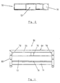
- conveyor section 10 includes a frame 34 which supports a plurality of sprockets or wheels 36 and an endless conveyor belt 50 which extends over and between sprockets 36 to define conveying surface 22.
- sprockets 36 inhibit lateral movement of belt 50 so belt 50 stays in alignment.
- Frame 34 includes a pair of opposed side frame members 40 and 42 and a guard or side rail 43 positioned over side frame 40 to prevent articles from falling off conveyor section 10.
- Belt 50 preferably comprises a light weight low friction belt, such as is available from Morse of Emerson Power Transmission.
- belt 50 preferably has a solid top surface to provide maximum support to the articles and also a flat smooth surface to minimize catch points, which could otherwise inhibit the transfer of the articles across the belt.
- Sprockets 36 are supported on and mounted to a pair spaced apart shafts 38a and 38b which are joumaled in side frame members 40 and 42 of frame 34.
- Shaft 38b comprises a drive shaft and is driven by a motor and reducer 44 and gearing 46, which is mounted to drive shaft 38b.
- Motor 44 includes a drive gear 48 which is coupled by a conventional belt, such as a cog type belt or v-belt or the like, or drive chain 49 to gear 46.
- belt 50 is continuously moving.
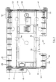
- transfer assembly 12 includes a pusher member or fence 52 which extends transversely across conveying surface 22 and straddles the length of conveying surface 22 and a pair of downwardly depending sides 54.
- Pusher member 52 preferably extends across the entire length of conveyor section 10 and, further, preferably includes a solid pressing surface 53, which is spaced above conveying surface 22 of conveyor belt 50 preferably no more than about ⁇ inch to avoid articles from getting jammed under pusher member 52.
- pusher member 52 is preferably formed from a light weight member, such as a light weight metal or a plastic material, such as aluminum, which forms a vertical fence or vertical pushing surface 53 and may optionally include an impact absorbing cover or outer layer, such as rubber.
- a light weight member such as a light weight metal or a plastic material, such as aluminum
- pushing surface 53 is formed by a relatively thin sheet or panel member with mounting flanges 53a and 53b for mounting to sides 54.
- pusher member 52 may include a wiper, such as a rubber skirt or brush, at its lower edge to ensure that loose straps or the like are moved along with the article being transferred by pusher member 52.
- wiper such as a rubber skirt or brush
- pusher member 52 may comprise a foraminous sheet or panel but preferably covered by an impact absorbing layer, such as foam or the like. In this manner, the weight of pusher member 52 is reduced while maintaining a continuous pushing surface without catch-points.
- pusher member 52 In its holding non-activated position, pusher member 52 is positioned at side frame member 42 (shown in solid lines in FIG. 5) adjacent conveying surface 22. As will be more fully described below and best seen in FIG. 5, when activated pusher member 52 moves over conveying surface 22 in a generally horizontal and parallel motion perpendicular to the movement of belt 50 over first portion 26 to a fully extended position adjacent second portion 28 (shown in phantom in FIG. 5) to move an article being conveyed on belt 50 so that the article will be aligned and delivered to conveyor section 16. As noted above, pusher member 52 straddles conveying surface 22 and includes downwardly depending sides 54 which mount pusher member 52 to frame 34.
- transverse member or yoke assembly 56 Extending transversely across conveyor section 10 beneath belt 50 is a transverse member or yoke assembly 56, which translates pusher member 52 across conveying surface 22.
- transverse member 56 is mounted to frame 34 by linear bearings 57 on a pair of rails 60, for example linear race support rails, which are respectively mounted to frame 34 by a pair of angle members 58. In this manner, transverse member 56 can be moved laterally across conveyor section 10 beneath belt 50.
- Sides 54 of pusher member 52 comprise L-shaped members which include an inwardly projecting leg 54a which connect pusher member 52 to transverse member 56 by fasteners, such as mounting bolts 62, to movably mount pusher member 52 to frame 34. In this manner, as transverse member 56 moves along rails 60, pusher member 52 moves across conveying surface 22 to translate the article from first portion 26 to second portion 28 of conveying surface 22.
- transverse member 56 comprises a frame 64 formed from a transverse angle member 66 and a pair of longitudinal angle members 68 and 70 which together form a generally U-shaped frame. Extending transversely across frame 64 is an inverted channel member 72 which faces downwardly from conveyor section 10. Frame 64 is reinforced by a second transverse angle member 74, which extends between angle members 68 and 70, and medial support angle members 76 and 78 which extend, respectively, from transverse angle member 66 to channel 72 and from transverse angle member 74 to channel 72. Angle members 76, 78, therefore, also provide lateral support to channel member 72.
- the components comprising transverse member 56 are rigidly interconnected, for example by welding.
- Leg portions 78 and 80 of longitudinal angle members 68 and 70 provide mounting surfaces for fasteners 62 and thus together with pusher member 52 form a substantially rigid movable assembly. It should be understood, however, that other open cross-section members or closed cross-section members, such as tubular members, can be used to form frame 64.
- transverse member 56 and pusher member 52 are moved laterally across conveyor section 10 on rails 60 by a driver 80.
- Driver 80 includes a motor 82 with a drive shaft 84 and a driver arm 86.
- Motor 82 preferably comprises an AC motor, for example 120 Volt AC 3/4 HP motor, and rotates drive shaft 84 360°, preferably at a constant angular velocity.
- Drive shaft 84 is drivingly coupled to arm 86 and, therefore when driven by motor 82, drive shaft 84 rotates drive arm 86 in a 360° circular path, which moves transverse member 56 and pusher member 52 across first portion 26 of conveying surface 22 between their holding positions (shown in solid in FIG. 5) and extended positions (shown in phantom in FIG.
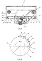
- a roller or wheel 88 is mounted to the end portion 86a of driver arm 86 by a pin or shaft 88a. Wheel 88 is positioned in channel 72 and engages inner surface 72a of channel 72. As motor 82 rotates drive shaft 84 about its vertical axis 84a and driver arm 86 rotates in its circular path 90 (FIG. 4A), wheel 88 rolls along inner surface 72a of channel 72.
- driver arm 86 when driver arm 86 is in its initial position or zero position 92, the angular velocity of driver arm 86 is generally parallel to the direction of flow of conveying surface 22. As driver arm 86 rotates in a counter-clockwise (or clockwise direction), the angular velocity of arm 86 generates a lateral force 94 on channel 72 with wheel 88 which moves pusher member 52 across conveying surface 22. Preferably, arm 86 is rotated at a generally constant angular velocity. As arm 86 continues to move through its circular path 90, the lateral component of the angular velocity increases as illustrated in FIG. 4A.
- the maximum lateral force 94' occurs when arm 86 is rotated to a 90° position 96, where all the momentum of arm 86 and wheel 56 is imparted laterally to pusher member 52. In this manner, when pusher member 52 initially makes contact with the article on conveying surface 22, the pusher member 52 is moving slowly thus making a low impact on the article. As the pusher member 52 translates across conveying surface 22, the speed of pusher member 52 increases until arm 86 is at its 90° position 96. As arm 86 continues to move through its circular path the lateral force 94 decreases until it reaches zero again at position 98 when arm is 180° with respect to its initial zero position 92.
- driver arm 86 returns pusher member 52 to its initial retracted position adjacent conveying surface 22. Since driver arm 86 rotates at a constant angular velocity, the return speed of arm 86 matches the output stroke of transfer assembly 12. It can be appreciated that the control of the speed of pusher member is achieved mechanically. In addition, when pusher member 52 makes initial contact with the article, as described above, the impact is minimal.
- conveyor belt 50 runs constantly with transfer assembly 12 being selectively operated or actuated by a control mechanism, described below. It should be understood that the rate of transfer that can be achieved by conveyor section 10 varies depending on the application, but for example, conveyor section 10 can transfer, for example bags, in a range of about 20 bags per minute to 45 bags per minute.
- conveyor section 10 may vary depending on the application.
- the transfer assembly 12 is preferably selectively actuated, for example by the operator of the x-ray machine.
- conveyor section 10 may be positioned at an output end of an x-ray machine conveyor (such as represented by conveyor section 14) with the output end of the x-ray machine conveyor aligned with first portion 26 of conveyor surface 22.
- a take-away or diverter conveyor (such as represented by conveyor section 16) is then positioned on the output side of conveyor section 10 adjacent second portion 28 of conveying surface 22.
- a third optional conveyor section, such as conveyor section 32 may be placed adjacent the output end of first portion 26 of conveying surface 22 to deliver the articles or baggage to a pick-up area for the passengers passing through the inspection station.
- Transfer assembly 12 may be actuated by a controller 95, such as a PLC.
- Controller 95 selectively activates motor 84 to activate transfer assembly 12 to move from its retracted position adjacent conveyor section 22 to its extended position across first portion 26 and back to its retracted position in response to signals from the operator of the x-ray machine. For example, when an operator of the x-ray machine detects that an article or baggage requires further inspection, such as manual inspection, the operator will, for example, press a button or the like which sends a signal to controller 95 to initiate the transfer sequence. Therefore, when no signal is received, article A is allowed to transfer across conveying surface 22 to an optional receiving conveyor, such as conveyor 32. It should be understood that controller 95 may receive input from other sources other than the operator of the x-ray machine.
- a photo-eye 96 may be positioned on conveyor section 10 to detect when the article in question transfers onto conveyor section 10. In this manner, when the controller receives the signal from the operator of the x-ray machine and the signal from the photo-eye, the controller will actuate the transfer assembly 12 to move the article across first portion 26 to second portion 28 of conveyor surface 22.
- a second photo-eye 98 may be positioned at the home position of the pusher member such that when the motor makes a full revolution and the pusher member is returned to its home position, the photo-eye will generate a signal which is transferred to controller 95 to stop motor 82, leaving pusher member 52 in its home or holding position until it is then activated again by the operator. It should be understood that the transfer assembly may be used in a number of different applications, for example, conveyor section 10 may be used in material handling or the like.
- Conveyor section 110 is suitable for positioning between a first, incoming conveyor section 114 and a second outgoing conveyor section 132 to translate one or more articles A to an adjacent generally parallel conveyor section 116.
- Conveyor section 110 is of similar construction to conveyor section 10 but has a conveying surface with approximately a width equal to the width of conveyor section 114 and 132 and is, therefore, approximately half of the width of conveyor section 10.
- Transfer assembly 112 is of similar construction to transfer assembly 12 of the previous embodiment and includes a pusher member 152 which translates across the conveying surface of conveyor section 110 to selectively translate one or more articles at a 90° angle to the flow of the articles across conveyors 114 and 132.
- conveyor section 110 includes a conveying surface 122 over which the article is moved when transfer assembly 112 is activated. Additionally, since the article is translated laterally for delivery to conveyor section 116, conveyor section 110 does not include a rail such as rail 43 of conveyor section 10 since the article must transfer across the full width of conveying surface 122 of conveyor section 110 and over the free edge of conveying surface 122 for delivery onto conveying surface 120 of conveyor section 116 as will be understood by those skilled in the art. In addition, transfer assembly 112 preferably moves across the full width of the conveying surface 122 of conveyor section 110 in order to transfer article A onto surface 120 of conveyor section 116.
- pusher member 152 moves across conveying surface 122 at a first speed to contact article A and then moves article A across the conveying surface 122 a second faster speed in order to provide a high sortation rate.
- the speed of conveying surface 122 along the direction of flow is generally matched with the speed of the conveying surface 120 of conveyor section 116. In this manner, the impact on article A is further minimized.
- Conveyor section 210 is of similar construction to conveyor section 110 and includes a pusher member 252 which translates across conveying surface 222 of conveyor section 210 for translating an article A across conveying surface 222 for delivery to conveyor section 216.
- Conveying section 216 includes a conveying surface 220 that defines a direction of flow generally orthogonal to the direction of flow of conveyor sections 214 and 232 and, further, to the direction of flow of conveying surface 222 of conveyor section 210.
- transverse member 56 frame 34, or pusher member 52 may be varied, including for example, by adding further reinforcing members or by eliminating reinforcing members. Therefore, it will be understood that the embodiments shown in the drawings and described above are merely for illustrative purposes, and are not intended to limit the scope of the invention which is defined by the claims which follow as interpreted under the principles of patent law including the doctrine of equivalents.
Landscapes
- Engineering & Computer Science (AREA)
- Mechanical Engineering (AREA)
- Special Conveying (AREA)
- Discharge Of Articles From Conveyors (AREA)
- Intermediate Stations On Conveyors (AREA)
- Relays Between Conveyors (AREA)
- Attitude Control For Articles On Conveyors (AREA)
- Branching, Merging, And Special Transfer Between Conveyors (AREA)
Description
Claims (30)
- A conveyor system comprising a transfer assembly (12) for transferring articles (A) between a first conveyor section (14) and a second conveyor section (16), the second conveyor section (16) being offset laterally from the first conveyor section (14), said transfer assembly comprising:characterized bya conveying surface (22) defining a direction of flow, said conveying surface (22) having a first portion (26) for aligning with the first conveyor section (14) for receiving articles (A) from the first conveyor and a second portion (28) for aligning with the second conveyor section (16) for transferring articles (A) to the second conveyor section (16);
a pusher (30) adapted to move laterally in a direction generally orthogonal to said direction of flow across said first portion (26) of said conveying surface (22) from a retracted position adjacent said first portion (26) to an extended position across said first portion (26) adjacent said second portion (28) for translating an article (A) being conveyed on said first portion (26) of said conveying surface (22) to said second portion (28) of said conveying surface (22) in said direction generally orthogonal to said direction of flow for transferring the article (A) from the first conveyor section (14) to the second conveyor section (16), said pusher (30) including downwardly depending portions (54) straddling said conveying surface (22), and said downwardly depending portions (54) being movable supported by a transverse member on a frame, said frame supporting said conveying surface (22), and said pusher (30) is movably supported by said frame (34). - The conveyor system according to Claim 1, wherein said conveying surface (22) comprises a driven belt.
- The conveyor system according to Claim 1, wherein said pusher (30) initially moves across said first portion (26) at a first speed to contact the article A, and said pusher (30) moving said article (A) across said first portion (26) a second speed, wherein said first speed is less than said second speed whereby said pusher (30) generates a low impact with the article (A).
- The conveyor system according to Claim 3, wherein said pusher (30) is movably supported by said frame (34) by a pair of rails (60).
- The conveyor system according to Claim 3, wherein said downwardly depending portions (54) are movably supported by said transverse member (56) on said frame (34).
- The conveyor system according to Claim 5, wherein said transverse member (56) is moved laterally across said frame (34) by a rotating arm (86).
- The conveyor system according to Claim 6, wherein said rotating arm (86) includes a wheel (88), said wheel engaging said transverse member (56) and driving said transverse member (56) to move said pusher (30) from said retracted position to said fully extended position and back to said retracted position.
- The conveyor system according to Claim 6, wherein said rotating arm (86) rotates 180° to drive said pusher (30) from said retracted position to said fully extended position adjacent said second portion of said conveying surface.
- The conveyor system according to Claim 1 wherein the conveying surface (22) of a third conveyor section (10)having a width dimension spanning across said conveying surfaces (20) of said first and second conveyor sections (14), (16) and a length dimension initiating at said output end (24) of said first conveyor section (14) and terminating at said input end (29) of said second conveyor section (16).
- The conveyor system according to Claim 9, wherein said transfer assembly (12) is adapted to selectively translate an article (A) conveyed on said conveying surface (22) between said first portion (26) and said second portion (28).
- The conveyor system according to Claim 10, wherein said pusher (30) includes downwardly depending portions (54), said downwardly depending portions (54) of said pusher (30) being interconnected by a transverse member (56), and said transverse member (56) supported by rails (60).
- The conveyor system according to Claim 11, wherein said transverse member (56) is driven by said driver (80) and moves said pusher (30) between said retracted position to said fully extended position.
- The conveyor system according to Claim 12, wherein said driver (80) includes a wheel (88), said wheel (88) engaging said transverse member (56) to drive said transverse member (56).
- The conveyor system according to Claim 13, wherein said wheel (88) is driven in a circular path (90) to move said pusher (30) across said first portion (26) of said conveying surface (22).
- The conveyor system according to Claim 14, wherein said wheel (88) is driven in said circular path (90) with a constant angular velocity whereby said pusher (30) moves a first speed over said first portion (26) to contact the article (A)conveyed on said conveying surface (22) and moves the article (A) across said first portion (26) a second speed faster than said first speed whereby the impact on the article (A) is minimized while maintaining a high sortation rate.
- The conveyor system according to Claim 15, wherein said transverse member (56) includes a transverse channel (72), said wheel (88) engaging said transverse channel (72) to move said pusher (30) between said retracted position and said fully extended position.
- The conveyor system according to Claim 10, wherein said third conveyor section (10) includes a frame (34), said conveying surface (22) rotatably supported on said frame (34).
- The conveyor system according to Claim 17, wherein said conveying surface (22) comprises a rotatable belt.
- The conveyor system according to Claim 17, wherein said pusher (30) is movably supported by said frame (34) on a pair of rails (60).
- The conveyor system according to Claim 19, wherein said transfer assembly (12) initially moves across said first portion (26) of said conveying surface (22) a first speed to contact the article (A)and moves the article (A) across said first portion (26) a second speed, wherein said first speed is less than said second speed to minimize the impact of the transfer assembly on the article (A).
- The conveyor system according to Claim 9, wherein said pusher (30) initially moves across said first portion (26) of said conveying surface (22) a first speed to contact the article (A), and said pusher (30) moving the article (A) a second speed across the conveying surface (22) wherein said first speed is less than said second speed to minimize the impact on the article(A).
- The conveyor system according to Claim 9, further comprising a driver (80) and a driver arm (86), said driver (80) rotating said driver arm (86), said driver arm (86) moving said pusher (30) across said first portion (26) of said conveying surface (22).
- The conveyor system according to Claim 22, wherein said driver arm (86) rotates in a circular path (90).
- The conveyor system according to Claim 23, wherein said driver arm (86) initially moves said pusher member (30) at a first speed to provide a low impact with the article (A) and accelerates said pusher member (30) to move the article (A) across said first portion (26) of said conveying surface (22) a second speed greater than said first speed.
- The conveyor system according to Claim 24, wherein said driver arm (86) rotates at a generally constant velocity.
- The conveyor system according to Claim 24, wherein said third conveyor section (10) includes a frame (34), said conveying surface (22) supported by said frame (34).
- The conveyor system according to Claim 25, wherein said driver arm (86) de-accelerates said pusher member (30) when said pusher member (30) approaches said extended position whereby the momentum of the article (A) is sufficiently decreased to reduce the momentum of the article (A) when it moves to said second portion (28) of said conveying surface (22).
- The conveyor system The according to Claim 1, further comprising a driver (80) and a driver arm (86) rotated by said driver (80), said driver arm moving said pusher (30) across said conveying surface (22).
- The conveyor system according to Claim 28, wherein said driver arm rotates in a circular path (90).
- The conveyor system according to Claim 29, wherein said driver arm rotates at a generally constant angular velocity.
Applications Claiming Priority (3)
| Application Number | Priority Date | Filing Date | Title |
|---|---|---|---|
| US09/596,357 US6446782B1 (en) | 2000-06-16 | 2000-06-16 | Shuttle top diverter |
| US596357 | 2000-06-16 | ||
| PCT/EP2001/006696 WO2001096218A2 (en) | 2000-06-16 | 2001-06-13 | Shuttle top diverter |
Publications (2)
| Publication Number | Publication Date |
|---|---|
| EP1289864A2 EP1289864A2 (en) | 2003-03-12 |
| EP1289864B1 true EP1289864B1 (en) | 2004-12-08 |
Family
ID=24386989
Family Applications (1)
| Application Number | Title | Priority Date | Filing Date |
|---|---|---|---|
| EP01964980A Expired - Lifetime EP1289864B1 (en) | 2000-06-16 | 2001-06-13 | Shuttle top diverter |
Country Status (10)
| Country | Link |
|---|---|
| US (1) | US6446782B1 (en) |
| EP (1) | EP1289864B1 (en) |
| JP (1) | JP2004503449A (en) |
| AU (2) | AU8574201A (en) |
| BR (1) | BR0111994A (en) |
| CA (1) | CA2412051A1 (en) |
| DE (1) | DE60107676T2 (en) |
| ES (1) | ES2233676T3 (en) |
| MX (1) | MXPA02012435A (en) |
| WO (1) | WO2001096218A2 (en) |
Families Citing this family (24)
| Publication number | Priority date | Publication date | Assignee | Title |
|---|---|---|---|---|
| US6812426B1 (en) * | 2000-07-24 | 2004-11-02 | Rapiscan Security Products | Automatic reject unit spacer and diverter |
| US8275091B2 (en) | 2002-07-23 | 2012-09-25 | Rapiscan Systems, Inc. | Compact mobile cargo scanning system |
| US7963695B2 (en) | 2002-07-23 | 2011-06-21 | Rapiscan Systems, Inc. | Rotatable boom cargo scanning system |
| US7080725B2 (en) * | 2002-12-03 | 2006-07-25 | Sanki Engineering Co., Ltd. | Sorting conveyor provided with cross sorter |
| JP4355513B2 (en) * | 2002-12-03 | 2009-11-04 | 三機工業株式会社 | Sorting conveyor with cross sorter |
| US6928141B2 (en) | 2003-06-20 | 2005-08-09 | Rapiscan, Inc. | Relocatable X-ray imaging system and method for inspecting commercial vehicles and cargo containers |
| DE10340868B4 (en) * | 2003-09-04 | 2005-09-29 | Siemens Ag | Conveyor system, in particular an airport baggage conveyor system, for the transport of general cargo serving containers |
| CN101027236A (en) * | 2004-06-21 | 2007-08-29 | 西门子共同研究公司 | High-rate space efficient article singulator |
| US7471764B2 (en) | 2005-04-15 | 2008-12-30 | Rapiscan Security Products, Inc. | X-ray imaging system having improved weather resistance |
| US20090034055A1 (en) * | 2007-07-31 | 2009-02-05 | Gibson Gary A | Plasmon-based color tunable devices |
| GB0803641D0 (en) | 2008-02-28 | 2008-04-02 | Rapiscan Security Products Inc | Scanning systems |
| GB0803644D0 (en) * | 2008-02-28 | 2008-04-02 | Rapiscan Security Products Inc | Scanning systems |
| GB0809110D0 (en) | 2008-05-20 | 2008-06-25 | Rapiscan Security Products Inc | Gantry scanner systems |
| JP2012200618A (en) * | 2011-03-23 | 2012-10-22 | Anritsu Sanki System Co Ltd | Sorting apparatus |
| US9218933B2 (en) | 2011-06-09 | 2015-12-22 | Rapidscan Systems, Inc. | Low-dose radiographic imaging system |
| AU2014212158B2 (en) | 2013-01-31 | 2017-04-20 | Rapiscan Systems, Inc. | Portable security inspection system |
| US9067740B2 (en) * | 2013-03-15 | 2015-06-30 | Intelligrated Headquarters, Llc | Remotely driven shuttle car |
| US9409716B2 (en) * | 2014-06-13 | 2016-08-09 | Bastian Solutions, Llc | Cross belt slat sorter |
| US9493308B2 (en) | 2014-08-11 | 2016-11-15 | Datalogic ADC, Inc. | Cross-belt system and automated item diversion |
| JP6332143B2 (en) * | 2015-05-25 | 2018-05-30 | 株式会社ダイフク | Picking equipment |
| EP3980358B1 (en) * | 2019-05-30 | 2024-10-02 | Material Handling Systems, Inc. | Rejection mechanism for a conveyor system |
| CN111729852B (en) * | 2020-04-23 | 2022-07-05 | 北京京东乾石科技有限公司 | Sorting vehicle, goods sorting system and goods sorting method |
| NL2027658B1 (en) * | 2021-02-26 | 2022-09-20 | Vanderlande Ind Bv | Transport system comprising several transport units for transporting products |
| CN117775668A (en) * | 2023-12-21 | 2024-03-29 | 斐科腾智能科技(青岛)有限公司 | Swinging diversion conveying mechanism and conveying device |
Citations (1)
| Publication number | Priority date | Publication date | Assignee | Title |
|---|---|---|---|---|
| US6068105A (en) * | 1997-09-19 | 2000-05-30 | Mannesmann Dematic Rapistan Corp. | Low impact article diverter assembly |
Family Cites Families (24)
| Publication number | Priority date | Publication date | Assignee | Title |
|---|---|---|---|---|
| DE311699C (en) | 1900-01-01 | |||
| US933818A (en) | 1908-12-26 | 1909-09-14 | John F Beatty | Bait-holder. |
| US3026988A (en) | 1959-04-06 | 1962-03-27 | Mathews Conveyer Co | Article transfer device |
| US3045801A (en) | 1960-03-30 | 1962-07-24 | Stewart Warner Corp | Transfer mechanism |
| US3246733A (en) | 1962-08-22 | 1966-04-19 | Fmc Corp | Article handling mechanism |
| DE2620036C3 (en) | 1976-05-06 | 1981-09-24 | Sandvik Conveyor Gmbh, 7012 Fellbach | Stripping device for conveyor belts |
| JPS52141958A (en) | 1976-05-21 | 1977-11-26 | Nippon Sandobitsuku Kk | Apparatus for pushing goods out of belt conveyor |
| FR2448944B1 (en) | 1979-02-13 | 1986-03-28 | Melius App Manutention | TRANSPORTATION AND SORTING PLANT FOR OBJECTS, ESPECIALLY MESSAGING PACKAGES |
| DE2917286A1 (en) | 1979-04-27 | 1980-11-06 | Bernhard Heuft | DEVICE FOR LATERALLY DEFLECTING PARTS FROM A FIRST MOTORWAY TO A SECOND MOTORWAY |
| DE3116991A1 (en) * | 1981-04-29 | 1982-11-18 | C. Keller GmbH u. Co KG, 4530 Ibbenbüren | Apparatus for conveying green ceramic bricks, especially roof tiles |
| US4815582A (en) * | 1981-12-24 | 1989-03-28 | Francesco Canziani | Feeding apparatus particularly for machines for the conveyance and sorting of objects |
| US4441604A (en) | 1982-06-24 | 1984-04-10 | Bae Automated Systems, Inc. | Pusher mechanism |
| JPS5836820A (en) | 1982-06-30 | 1983-03-03 | Daifuku Co Ltd | Release device of conveyed article |
| JPS5982220A (en) | 1982-10-30 | 1984-05-12 | Akito Tamura | Distributor for transporting object |
| JPS60232320A (en) | 1984-05-01 | 1985-11-19 | Sandobitsuku Kk | Diverter |
| IT211603Z2 (en) * | 1985-12-20 | 1989-04-07 | Canziani Francesco | TRANSPORT AND UNLOADING UNIT FOR SORTING OBJECTS. |
| US4643291A (en) | 1986-01-21 | 1987-02-17 | Rexnord Inc. | Linear articulated pusher |
| GB2223730B (en) | 1988-07-07 | 1991-11-20 | Post Office | Improved diverter |
| FR2670760B1 (en) | 1990-12-21 | 1995-07-21 | Fimec | DEVICE FOR DEVIATION OF OBJECTS MOVING ON A CONVEYOR. |
| JPH0725447A (en) * | 1993-07-08 | 1995-01-27 | Toyo Kanetsu Kk | Sorting method and device |
| US5452786A (en) | 1994-07-19 | 1995-09-26 | Rapistan Demag Corporation | High-speed paddle diverter |
| US6005211A (en) * | 1996-02-02 | 1999-12-21 | United Parcel Service Of America, Inc. | Method and apparatus for sorting articles using a matrix of conveyor cells |
| GB2300612B (en) * | 1995-04-25 | 1998-09-30 | Crisplant As | Conveyor |
| IT1297026B1 (en) * | 1997-12-29 | 1999-08-03 | Cml Handling Technology S P A | HIGH PRODUCTIVITY METHOD AND EQUIPMENT FOR PARCEL SORTING |
-
2000
- 2000-06-16 US US09/596,357 patent/US6446782B1/en not_active Expired - Lifetime
-
2001
- 2001-06-13 AU AU8574201A patent/AU8574201A/en active Pending
- 2001-06-13 DE DE60107676T patent/DE60107676T2/en not_active Expired - Fee Related
- 2001-06-13 MX MXPA02012435A patent/MXPA02012435A/en active IP Right Grant
- 2001-06-13 CA CA002412051A patent/CA2412051A1/en not_active Abandoned
- 2001-06-13 BR BR0111994-0A patent/BR0111994A/en not_active Application Discontinuation
- 2001-06-13 EP EP01964980A patent/EP1289864B1/en not_active Expired - Lifetime
- 2001-06-13 JP JP2002510368A patent/JP2004503449A/en active Pending
- 2001-06-13 ES ES01964980T patent/ES2233676T3/en not_active Expired - Lifetime
- 2001-06-13 WO PCT/EP2001/006696 patent/WO2001096218A2/en not_active Ceased
- 2001-06-13 AU AU2001285742A patent/AU2001285742B2/en not_active Ceased
Patent Citations (1)
| Publication number | Priority date | Publication date | Assignee | Title |
|---|---|---|---|---|
| US6068105A (en) * | 1997-09-19 | 2000-05-30 | Mannesmann Dematic Rapistan Corp. | Low impact article diverter assembly |
Also Published As
| Publication number | Publication date |
|---|---|
| JP2004503449A (en) | 2004-02-05 |
| ES2233676T3 (en) | 2005-06-16 |
| BR0111994A (en) | 2003-04-01 |
| WO2001096218A2 (en) | 2001-12-20 |
| MXPA02012435A (en) | 2003-06-06 |
| EP1289864A2 (en) | 2003-03-12 |
| CA2412051A1 (en) | 2001-12-20 |
| DE60107676T2 (en) | 2005-12-15 |
| AU8574201A (en) | 2001-12-24 |
| WO2001096218A3 (en) | 2002-05-10 |
| US6446782B1 (en) | 2002-09-10 |
| DE60107676D1 (en) | 2005-01-13 |
| AU2001285742B2 (en) | 2006-02-16 |
Similar Documents
| Publication | Publication Date | Title |
|---|---|---|
| US6446782B1 (en) | Shuttle top diverter | |
| AU2001285742A1 (en) | Shuttle top diverter | |
| US6619464B2 (en) | Vertical diverter assembly | |
| AU748014B2 (en) | Method of diverting an article from a conveyor by a pusher and device therefor | |
| US6860383B2 (en) | Positive displacement sorter | |
| US6533103B2 (en) | Transfer device for use between two conveyors | |
| US5217104A (en) | Device for deviating objects traveling on a conveyor | |
| CZ113093A3 (en) | Device for transferring a workpiece from one machine to another one | |
| US4961488A (en) | Device for transferring objects from a supply device to a take up device | |
| US3858707A (en) | Conveyor system | |
| JP2004503449A5 (en) | ||
| CN112474371A (en) | Turning plate sorting machine, turning plate sorting system, sorting method of turning plate sorting machine and supporting guide rail | |
| EP3696122B1 (en) | A cross-belt sorter | |
| EP1828033B1 (en) | Device for selectively diverting products sideways from a conveyor | |
| US4039070A (en) | Diverting conveyor system | |
| JP2001522341A (en) | Device for transferring goods between two conveyors | |
| US20210094763A1 (en) | Apparatus for transport and controlled discharge of products | |
| CN112474372A (en) | Overturning type sorting vehicle, overturning type sorting device, overturning type sorting system and overturning type sorting method | |
| US4723654A (en) | Apparatus for conveying a stack of bags | |
| JP3799525B2 (en) | Conveyor posture change device | |
| JP4569202B2 (en) | Sorting equipment | |
| JPH06127671A (en) | Carrying device | |
| JPH0641934Y2 (en) | Sorting device | |
| JPH0748022A (en) | Sorting method and sorting device | |
| JPH07257736A (en) | Conveyor equipment |
Legal Events
| Date | Code | Title | Description |
|---|---|---|---|
| PUAI | Public reference made under article 153(3) epc to a published international application that has entered the european phase |
Free format text: ORIGINAL CODE: 0009012 |
|
| 17P | Request for examination filed |
Effective date: 20021121 |
|
| AK | Designated contracting states |
Kind code of ref document: A2 Designated state(s): AT BE CH CY DE DK ES FI FR GB GR IE IT LI LU MC NL PT SE TR |
|
| AX | Request for extension of the european patent |
Extension state: AL LT LV MK RO SI |
|
| RIN1 | Information on inventor provided before grant (corrected) |
Inventor name: PATRICK, RICHARD |
|
| 17Q | First examination report despatched |
Effective date: 20030829 |
|
| RBV | Designated contracting states (corrected) |
Designated state(s): DE ES FR GB IT NL |
|
| GRAP | Despatch of communication of intention to grant a patent |
Free format text: ORIGINAL CODE: EPIDOSNIGR1 |
|
| GRAS | Grant fee paid |
Free format text: ORIGINAL CODE: EPIDOSNIGR3 |
|
| GRAA | (expected) grant |
Free format text: ORIGINAL CODE: 0009210 |
|
| AK | Designated contracting states |
Kind code of ref document: B1 Designated state(s): DE ES FR GB IT NL |
|
| REG | Reference to a national code |
Ref country code: GB Ref legal event code: FG4D |
|
| REG | Reference to a national code |
Ref country code: IE Ref legal event code: FG4D |
|
| REF | Corresponds to: |
Ref document number: 60107676 Country of ref document: DE Date of ref document: 20050113 Kind code of ref document: P |
|
| REG | Reference to a national code |
Ref country code: ES Ref legal event code: FG2A Ref document number: 2233676 Country of ref document: ES Kind code of ref document: T3 |
|
| PLBE | No opposition filed within time limit |
Free format text: ORIGINAL CODE: 0009261 |
|
| STAA | Information on the status of an ep patent application or granted ep patent |
Free format text: STATUS: NO OPPOSITION FILED WITHIN TIME LIMIT |
|
| ET | Fr: translation filed | ||
| 26N | No opposition filed |
Effective date: 20050909 |
|
| PGFP | Annual fee paid to national office [announced via postgrant information from national office to epo] |
Ref country code: DE Payment date: 20070822 Year of fee payment: 7 |
|
| PGFP | Annual fee paid to national office [announced via postgrant information from national office to epo] |
Ref country code: IT Payment date: 20080626 Year of fee payment: 8 |
|
| PGFP | Annual fee paid to national office [announced via postgrant information from national office to epo] |
Ref country code: ES Payment date: 20080714 Year of fee payment: 8 Ref country code: NL Payment date: 20080618 Year of fee payment: 8 |
|
| PGFP | Annual fee paid to national office [announced via postgrant information from national office to epo] |
Ref country code: FR Payment date: 20080616 Year of fee payment: 8 |
|
| PGFP | Annual fee paid to national office [announced via postgrant information from national office to epo] |
Ref country code: GB Payment date: 20080616 Year of fee payment: 8 |
|
| PG25 | Lapsed in a contracting state [announced via postgrant information from national office to epo] |
Ref country code: DE Free format text: LAPSE BECAUSE OF NON-PAYMENT OF DUE FEES Effective date: 20090101 |
|
| GBPC | Gb: european patent ceased through non-payment of renewal fee |
Effective date: 20090613 |
|
| NLV4 | Nl: lapsed or anulled due to non-payment of the annual fee |
Effective date: 20100101 |
|
| REG | Reference to a national code |
Ref country code: FR Ref legal event code: ST Effective date: 20100226 |
|
| PG25 | Lapsed in a contracting state [announced via postgrant information from national office to epo] |
Ref country code: FR Free format text: LAPSE BECAUSE OF NON-PAYMENT OF DUE FEES Effective date: 20090630 |
|
| PG25 | Lapsed in a contracting state [announced via postgrant information from national office to epo] |
Ref country code: GB Free format text: LAPSE BECAUSE OF NON-PAYMENT OF DUE FEES Effective date: 20090613 |
|
| PG25 | Lapsed in a contracting state [announced via postgrant information from national office to epo] |
Ref country code: NL Free format text: LAPSE BECAUSE OF NON-PAYMENT OF DUE FEES Effective date: 20100101 |
|
| REG | Reference to a national code |
Ref country code: ES Ref legal event code: FD2A Effective date: 20090615 |
|
| PG25 | Lapsed in a contracting state [announced via postgrant information from national office to epo] |
Ref country code: ES Free format text: LAPSE BECAUSE OF NON-PAYMENT OF DUE FEES Effective date: 20090615 |
|
| PG25 | Lapsed in a contracting state [announced via postgrant information from national office to epo] |
Ref country code: IT Free format text: LAPSE BECAUSE OF NON-PAYMENT OF DUE FEES Effective date: 20090613 |