EP1289672B1 - Apparatus and method for coating the exterior surface of a pipe - Google Patents
Apparatus and method for coating the exterior surface of a pipe Download PDFInfo
- Publication number
- EP1289672B1 EP1289672B1 EP01934125A EP01934125A EP1289672B1 EP 1289672 B1 EP1289672 B1 EP 1289672B1 EP 01934125 A EP01934125 A EP 01934125A EP 01934125 A EP01934125 A EP 01934125A EP 1289672 B1 EP1289672 B1 EP 1289672B1
- Authority
- EP
- European Patent Office
- Prior art keywords
- pipe
- gallery
- coating
- coating material
- exterior surface
- Prior art date
- Legal status (The legal status is an assumption and is not a legal conclusion. Google has not performed a legal analysis and makes no representation as to the accuracy of the status listed.)
- Expired - Lifetime
Links
Images


Classifications
-
- B—PERFORMING OPERATIONS; TRANSPORTING
- B05—SPRAYING OR ATOMISING IN GENERAL; APPLYING FLUENT MATERIALS TO SURFACES, IN GENERAL
- B05B—SPRAYING APPARATUS; ATOMISING APPARATUS; NOZZLES
- B05B13/00—Machines or plants for applying liquids or other fluent materials to surfaces of objects or other work by spraying, not covered by groups B05B1/00 - B05B11/00
- B05B13/02—Means for supporting work; Arrangement or mounting of spray heads; Adaptation or arrangement of means for feeding work
- B05B13/04—Means for supporting work; Arrangement or mounting of spray heads; Adaptation or arrangement of means for feeding work the spray heads being moved during spraying operation
- B05B13/0463—Installation or apparatus for applying liquid or other fluent material to moving work of indefinite length
- B05B13/0484—Installation or apparatus for applying liquid or other fluent material to moving work of indefinite length with spray heads having a circular motion, e.g. being attached to a rotating supporting element
- B05B13/0489—Installation or apparatus for applying liquid or other fluent material to moving work of indefinite length with spray heads having a circular motion, e.g. being attached to a rotating supporting element around the moving work
-
- B—PERFORMING OPERATIONS; TRANSPORTING
- B05—SPRAYING OR ATOMISING IN GENERAL; APPLYING FLUENT MATERIALS TO SURFACES, IN GENERAL
- B05B—SPRAYING APPARATUS; ATOMISING APPARATUS; NOZZLES
- B05B13/00—Machines or plants for applying liquids or other fluent materials to surfaces of objects or other work by spraying, not covered by groups B05B1/00 - B05B11/00
- B05B13/02—Means for supporting work; Arrangement or mounting of spray heads; Adaptation or arrangement of means for feeding work
- B05B13/0207—Means for supporting work; Arrangement or mounting of spray heads; Adaptation or arrangement of means for feeding work the work being an elongated body, e.g. wire or pipe
-
- B—PERFORMING OPERATIONS; TRANSPORTING
- B05—SPRAYING OR ATOMISING IN GENERAL; APPLYING FLUENT MATERIALS TO SURFACES, IN GENERAL
- B05B—SPRAYING APPARATUS; ATOMISING APPARATUS; NOZZLES
- B05B1/00—Nozzles, spray heads or other outlets, with or without auxiliary devices such as valves, heating means
- B05B1/26—Nozzles, spray heads or other outlets, with or without auxiliary devices such as valves, heating means with means for mechanically breaking-up or deflecting the jet after discharge, e.g. with fixed deflectors; Breaking-up the discharged liquid or other fluent material by impinging jets
- B05B1/262—Nozzles, spray heads or other outlets, with or without auxiliary devices such as valves, heating means with means for mechanically breaking-up or deflecting the jet after discharge, e.g. with fixed deflectors; Breaking-up the discharged liquid or other fluent material by impinging jets with fixed deflectors
- B05B1/265—Nozzles, spray heads or other outlets, with or without auxiliary devices such as valves, heating means with means for mechanically breaking-up or deflecting the jet after discharge, e.g. with fixed deflectors; Breaking-up the discharged liquid or other fluent material by impinging jets with fixed deflectors the liquid or other fluent material being symmetrically deflected about the axis of the nozzle
-
- B—PERFORMING OPERATIONS; TRANSPORTING
- B05—SPRAYING OR ATOMISING IN GENERAL; APPLYING FLUENT MATERIALS TO SURFACES, IN GENERAL
- B05B—SPRAYING APPARATUS; ATOMISING APPARATUS; NOZZLES
- B05B7/00—Spraying apparatus for discharge of liquids or other fluent materials from two or more sources, e.g. of liquid and air, of powder and gas
- B05B7/14—Spraying apparatus for discharge of liquids or other fluent materials from two or more sources, e.g. of liquid and air, of powder and gas designed for spraying particulate materials
- B05B7/1404—Arrangements for supplying particulate material
-
- B—PERFORMING OPERATIONS; TRANSPORTING
- B05—SPRAYING OR ATOMISING IN GENERAL; APPLYING FLUENT MATERIALS TO SURFACES, IN GENERAL
- B05B—SPRAYING APPARATUS; ATOMISING APPARATUS; NOZZLES
- B05B7/00—Spraying apparatus for discharge of liquids or other fluent materials from two or more sources, e.g. of liquid and air, of powder and gas
- B05B7/14—Spraying apparatus for discharge of liquids or other fluent materials from two or more sources, e.g. of liquid and air, of powder and gas designed for spraying particulate materials
- B05B7/1481—Spray pistols or apparatus for discharging particulate material
- B05B7/1486—Spray pistols or apparatus for discharging particulate material for spraying particulate material in dry state
Definitions
- Exterior protective coating of an entire pipe may be accomplished by an electrostatic process in which a pipe that has an induced charge on its surface is rotated over a coating material having an opposing charge.
- a disadvantage of the prior art is that either the entire coating apparatus or the pipe must be rotated to achieve a full 360-degree coating of an area around the outer perimeter of the pipe.
- GB-A 2 285 592 discloses an apparatus for coating pipes, which comprises a rotary frame mounted within a non-rotating support frame encircling a pipe to be coated. Coating material is supplied through supply pipes to a supply port or chamber in a body portion of the support frame, from which it is supplied through radial ducts to spray heads in the inner circumference of the rotary frame. The rotary frame is rotated as the coating material is sprayed onto the pipe.
- US-A 2,357,144 describes an apparatus for painting flagpoles, which comprises an annular casing that surrounds the flagpole. Paint is delivered by compressed air through a manifold partially encircling the flagpole to several nozzles, from which it is sprayed onto the flagpole.
- An object of the present invention is to provide apparatus and method for applying a coating material around the complete perimeter of the exterior of a pipe without rotating the pipe or all components of the coating device.
- An outer stationary or stator element remains static whilst an inner rotor element is used to achieve a 360-degree perimetrical coating.
- Another object of the present invention is to provide apparatus and method for applying a coating material around the complete perimeter of the exterior of a pipe without rotating the pipe or the coating device.
- the entire coating device remains stationary whilst a 360-degree perimetrical coating of the pipe is achieved.
- the invention provides an apparatus for application of a coating material to the exterior surface of a pipe comprising a stator arranged in use to be disposed around the exterior surface of the pipe, a substantially annular rotor rotationally disposed within the stator and arranged to have in use a common central axis with the pipe, at least one gallery extending substantially around the axis, at least one coating head having an internal passage for the coating material and an opening arranged in use to be in close contact with the exterior surface of the pipe, the internal passage connected to the at least one gallery, a drive means for rotating the rotor and the at least one coating head around the exterior of the pipe, a means for supplying the coating material from an external source to the at least one gallery; characterised in that the at least one gallery is enclosed by the rotor; the means for supplying the coating material from the external source to the at least one internal gallery comprises at least one outlet mounted on the stator and projecting into the gallery for injecting the coating material into the at least one internal gallery and a means for applying positive air pressure to the at
- the invention also provides a method of applying a coating material to the exterior surface of a pipe comprising the steps of disposing a rotating element around the exterior surface of the pipe substantially within a stationary element, rotating the rotating element, supplying the coating material to at least one internal gallery within said elements, and ejecting the coating material onto the exterior surface of the pipe from one or more coating heads having an internal passage connected to the at least one gallery characterized by providing the at least one gallery internally within the rotating element, injecting the coating material into the at least one internal gallery from at least one outlet mounted on the stationary element and projecting into the gallery, and supplying at a positive air pressure the coating material onto the exterior surface of the pipe through the at least one coating head.
- FIG. 1 though FIG. 5 a first example of coating apparatus 10 of the present invention.
- Substantially annular rotor elements 20 and 22 are suitably joined together to form a rotor.
- a gallery 24 (hidden and shown by dashed lines in FIG. 1 ) that extends substantially around the rotor.
- the rotor has a central axis that is common with the central axis of pipe 90 (shown in cross-section in FIG. 1 ).
- Stator elements 26 and 28 are disposed around the rotor and suitably joined together to form a stator.
- Means for providing free rotation of the rotor relative to the stator such as the ball bearings 30 shown in FIG. 2 are provided.
- stator and rotor for the example in FIG. 1 are formed from two elements, they may be fabricated in different fashion to suit other materials and methods of assembly without deviating from the scope of the invention.
- stator in FIG.1 is shown as a substantially annular structure, in other examples, the stator may be of another shape, such as rectangular.
- the stator and rotor may be machined from hard anodized aluminum and coated with a friction reducing material such as TEFLON to provide a favorable boundary surface in the internal passages as further described below.
- a suitable, but not limiting, coating material is a fusion-bonded epoxy in powdered form.
- the coating material is provided from an external source via a suitable pipe or tubing (not shown in the drawings) that is connected to material port 32 of vacuum displacement pump 34 .
- Air port 36 on the pump is connected to a regulated compressed air supply (typically from 30 to 30 psi for this example) by suitable pipe or tubing (not shown in the drawings). Regulating the supply of air to a venturi in pump 34 controls the intake draw of coating material into the coating apparatus and provides the means for keeping the coating material within the apparatus under positive air pressure.
- fluidized powder can be used to describe the coating material as it mixes with the injected air and reduces in density to a state suitable for passage within the coating apparatus of the present invention.
- a particular advantage of the present invention is that the non-rotating rotor provides a stationary structure for mounting each vacuum displacement pump. Therefore, the coating material and compressed air connections to each pump are not complicated by connecting to a rotating element.
- the coating apparatus 10 shown in FIG. 1 uses two vacuum displacement pumps disposed on one of the two stator elements, other examples of the invention can have a different number of pumps that are attached to one stator face, or distributed between both stator faces.
- Seals 40 serve as means to keep the powder within the gallery as the rotor rotates relative to the stator and pump outlet 38 .
- the seals are designed to withstand the positive air pressure exerted on the powder within the gallery. As shown in FIG. 3 , pressurized air may optionally be blown into one or more ports 33 on the rotor to assist in maintaining a positive air pressure on the seals 40 .
- Coating material is ejected from the gallery 24 through one or more coating heads 42 that are attached to the rotor and have an internal passage connected to the gallery.
- the coating material is a thermoplastic material
- pipe 90 will be preheated prior to the application of coating material to fuse the material onto the exterior surface of the pipe.
- the exterior surface of pipe 90 can be grit blasted prior to coating by providing a suitable grit from an external source via a suitable pipe or tubing that is connected to material port 32 of one or more of the vacuum pumps 34 .
- a suitable grit from an external source via a suitable pipe or tubing that is connected to material port 32 of one or more of the vacuum pumps 34 .
- one or more dedicated grit vacuum pumps can be provided around one or both of the stator faces.
- a coating head 42 can be provided with one or more interior diffusers 46 in the form of a disc or other shape to control the flow of coating material through the head and onto the exterior surface of the pipe.
- the coating head including opening 44 , can be configured as best to suit coating material ejection for a particular application.
- diffuser 46 deflects the fluidized powder to the side wall 45 of the coating head so that the powder exits opening 44 in a generally uniform flow profile across the entire width of the opening.
- each coating head is removably attached to the rotor so that it can be removed and exchanged with a head of differing length, or fitted with a length extension fitting so that differing diameters of pipe can be accommodated.
- Suitable drive means are provided to rotate the rotor.
- One method of driving the rotor is shown in FIG. 4 .
- Motor 48 is connected to sprocket 50 via output shaft 52 .
- a chain (not shown in the drawings) engages sprocket 50 and radially projected teeth (not shown in the drawings) on the circular side surface of the rotor to deliver rotational power from the drive motor to the rotor. Whilst two motors are used in this example, a differing number and configuration may be used to suit a specific application.
- stator and rotor can be formed as continuous elements around their circumferences.
- stator and rotor can include means for opening and closing around a section of pipe, such as two split or hinged members with interface boundaries 92 shown in FIG. 1.
- Either the pipe or the coating device may be moved in its axial direction to effect coating along the length of the pipe.
- the coating material is a thermoplastic material
- pipe 90 will be preheated prior to the application of coating material to fuse the material onto the exterior surface of the pipe.
- the gas may be supplied to one or more of air ports 36 or one or more dedicated gas ports provided around one or both of the stator faces to inject the gas into gallery 24 prior and during coating.
- air ports 36 or one or more dedicated gas ports provided around one or both of the stator faces to inject the gas into gallery 24 prior and during coating.
- a quench fluid either in liquid or gaseous form, can be supplied from an external source via a suitable pipe or tubing that is connected to material port 32 of one or more of the vacuum pumps 34 .
- a suitable pipe or tubing that is connected to material port 32 of one or more of the vacuum pumps 34 .
- one or more dedicated quench fluid pumps can be provided around one or both of the stator faces.
- suitable valve arrangements can be provided upstream of the input to material port 32 to facilitate selection of the substance that is fed to the port.
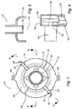
- FIG. 6 and FIG. 7 a second example of the coating apparatus 10 of the present invention.
- the apparatus comprises a substantially annular body 60 , which has a plurality of entry ports 62 protruding from it.
- the number of entry ports for a particular application is governed by the diameter of the pipe 90 (shown in cross-section in FIG. 6 and FIG. 7 ) that is being coated and are, in general, symmetrically arranged around its outer perimeter.
- the annular body 60 can be formed from two machined halves. Hard anodized aluminum is a suitable material.
- a coating of a friction reducing material such as TEFLON is preferable to provide a favorable boundary surface in the entry ports and other internal passages as further described below.
- a mixing chamber 64 is connected to each of the entry ports.
- the mixing chamber is used as a means to introduce the coating material into the entry port at a positive air pressure.
- the coating material is introduced into the mixing chamber from fitting 66 .
- Fitting 66 is attached to chamber 64 and has a material port 68 for connection to an external source of coating material via suitable pipe or tube (not shown in the drawings).
- Air port 70 in fitting 66 is connected to a regulated compressed air supply (generally with a range from 30 to 40 psi for the present example) by suitable pipe or tubing (not shown in the drawings).
- Regulating the supply of air to a venturi in fitting 66 controls the intake draw of coating material into the coating apparatus and provides the means for keeping the coating material (fluidized powder) within the apparatus under positive air pressure.
- Mixing chamber 64 has an air port 72 attached to it by which generally low pressure (in the range of 4 to 5 psi) and high volume (in the range of 20 to 25 cfm) air from a suitable source such as a low pressure air compressor (not shown in the figures) is supplied.
- the low-pressure air serves to force the coating material entering the mixing chamber from fitting 66 into entry port 62 and to further reduce the density of powder if required for a particular application.
- Intake chamber 74 within body 60 transfers the coating material from an entry port to compression chamber 76 that runs substantially around an inner diameter of body 60 (hidden and shown as dashed lines in FIG. 6 ).
- the intake chamber has a generally circular cross-section
- the compression chamber has a combination oval and funnel-shaped cross-section. Other shapes are suitable for the compression chamber as long as the chamber serves to compress the coating material under positive air pressure.
- the coating material is forced by air pressure down through compression chamber 76 and into diffusing chamber 78 .
- the diffusing chamber is a substantially oval passage that opens into the sides of gallery 80 .
- Interchangeable centre section 82 is a collar that is seated within the inner radial surface of annular body 60 to accommodate the outer diameter of the pipe 90 to be coated.
- One or more appropriate openings 84 are provided through the thickness of the centre section 82 to permit ejection of coating material onto the outer diameter of pipe 90 .
- opening 84 is a substantially continuous circumferential opening in the centre section to permit ejection of coating material 360 degrees around the perimeter of the pipe 90.
- neither the pipe 90 nor coating device 10 need to be rotated to achieve a complete coating around the perimeter of the pipe.
- satisfactory rotating means maybe provided with the coating device to rotate it if required for a particular coating process. Either the pipe or coating device may be moved in its axial direction to effect coating along the length of the pipe.
- the coating material is a thermoplastic material
- pipe 90 will be preheated prior to. the application of coating material to fuse the material onto the exterior surface of the pipe.
- the configuration of the coating apparatus 10 shown in FIG. 6 and FIG. 7, namely with four entry ports 62 arranged substantially 45 degrees apart from each other, can preferably (but not in limitation) be used to deposit a complete 360-degrees band of coating material around the exterior perimeter of a pipe having an outside diameter ranging from approximately 5 to 13 cm. For pipes of larger diameter, a greater number of entry ports can be used without deviating from the scope of the invention.
- body 60 can be formed as a continuous element around their circumferences.
- the body can include means for opening and closing around a section of pipe, such as two split or hinged members with interface boundaries 94 shown in FIG. 6.
- Suitable grit can be provided to material port 68 of one or more of the fittings 66 .
- one or more dedicated grit material and entry ports can be provided around the perimeter of annular body 60 for injecting grit into compression chamber 76 .
- a gas can be supplied to one or more air ports 70 prior and during coating.
- one or more dedicated gas ports can be provided to inject the gas into the intake and compression chamber.
- a quench fluid can be provided to material port 68 of one or more of the fittings 66 .
- one or more dedicated quench fluid fittings can be provided around the perimeter of annular body 60 .
- a magnetic induction heating assembly may be combined with the coating apparatus of the present invention to form a single stationary apparatus for preheating and coating around a complete circumferential area of the pipe.
Landscapes
- Application Of Or Painting With Fluid Materials (AREA)
- Coating Apparatus (AREA)
- Spray Control Apparatus (AREA)
Abstract
Description
Claims (15)
- An apparatus for application of a coating material to the exterior surface of a pipe comprising a stator (26, 28) arranged in use to be disposed around the exterior surface of the pipe, a substantially annular rotor (20, 22) rotationally disposed within the stator and arranged to have in use a common central axis with the pipe, at least one gallery (24) extending substantially around the axis, at least one coating head (42) having an internal passage for the coating material and an opening arranged in use to be in close contact with the exterior surface of the pipe, the internal passage connected to the at least one gallery (24), a drive means (48, 50, 52) for rotating the rotor and the at least one coating head around the exterior of the pipe, a means for supplying the coating material from an external source to the at least one gallery; characterised in that the at least one gallery (24) is enclosed by the rotor, the means for supplying the coating material from the external source to the at least one internal gallery comprises at least one outlet (38) mounted on the stator (26, 28) and projecting into the gallery for injecting the coating material into the at least one internal gallery (24) and a means for applying positive air pressure to the at least one internal gallery, whereby the coating material is forced by air pressure through the at least one internal gallery (24) and ejected onto the exterior surface of the pipe through the at least one coating head (42).
- The apparatus of claim 1 wherein the at least one outlet (38) is the outlet of at least one vacuum displacement pump (34) attached to the stator (26 and 28), the at least one vacuum displacement pump having a first port for connection to an external source of coating material and a second port for connection to an external source of compressed air for applying positive air pressure to the at least one internal gallery (24).
- The apparatus of claim 1 or 2 wherein sealing means (40) are provided between the at least one internal gallery (24) and the at least one outlet (38) to prevent release of the coating material from the at least one internal gallery (24).
- The apparatus of claim 3, comprising at least one air port (33) in the stator (26, 28), the air port (33) connected to a pressurized air source whereby a positive air pressure is maintained on the sealing means.
- The apparatus of any preceding claim, wherein the at least one coating head (42) has a diffusing means (46) within the internal passage of the at least one coating head.
- The apparatus of any preceding claim, comprising means for supplying a grit from an external source to the at least one internal gallery (24) and means for applying positive air pressure to the at least one internal gallery (24), whereby the grit is forced by air pressure through the at least one internal gallery and ejected onto the exterior surface of the pipe through the at least one coating head.
- The apparatus of any preceding claim further comprising means for supplying a gas from an external source to the at least one internal gallery (24) and means for applying positive air pressure to the at least one internal gallery (24), whereby the heated gas is forced by air pressure through the at least one internal gallery and ejected onto the exterior surface of the pipe through the at least one coating head.
- The apparatus of any preceding claim, comprising means for supplying a quench fluid from an external source to the at least one internal gallery (24) and means for applying positive air pressure to the at least one internal gallery (24), whereby the quench fluid is forced by air pressure through the at least one internal gallery and ejected onto the exterior surface of the pipe through the at least one coating head.
- The apparatus of any preceding claim, wherein the stator (26, 28) and the rotor (20, 22) include means for opening and closing around the pipe.
- The apparatus of any preceding claim, comprising at least one magnetic induction heater to heat the pipe prior to placement of the coating material onto the exterior surface of the pipe.
- A method of applying a coating material to the exterior surface of a pipe comprising the steps of disposing a rotating element (20, 22) around the exterior surface of the pipe substantially within a stationary element (26, 28), rotating the rotating element (20, 22), supplying the coating material to at least one internal gallery (24) within said elements (20, 22, 26, 28), and ejecting the coating material onto the exterior surface of the pipe from one or more coating heads (42) having an internal passage connected to the at least one gallery (24), characterized by providing the at least one gallery internally within the rotating element (20, 22), injecting the coating material into the at least one internal gallery (24) from at least one outlet (38) mounted on the stationary element (26, 28) and projecting into the gallery, and supplying at a positive air pressure the coating material onto the exterior surface of the pipe through the at least one coating head.
- The method of claim 11, further characterized by the steps of supplying at a positive air pressure a grit to the outlet (38) mounted on the stationary element (26, 28), transferring the grit from the stationary element (26, 28) to the gallery (24); and ejecting the grit onto the exterior surface of the pipe from one or more coating heads (42).
- The method of claim 11, further characterized by the steps of supplying at a positive air pressure a gas to the outlet (38) mounted on the stationary element (26, 28), transferring the gas from the outlet (38) to the at least one gallery (24), and ejecting the gas onto the exterior surface of the pipe from one or more coating heads (42).
- The method of claim 11, further characterized by the steps of supplying at a positive air pressure a quench liquid to the outlet (38) mounted on the stationary element (26, 28), transferring the quench liquid from the outlet (38) to the at least one gallery (24); and ejecting the quench liquid onto the exterior surface of the pipe from one or more coating heads (42).
- The method of claim 11, further characterized by the steps of connecting the at least one outlet (38) to a vacuum displacement pump (34) attached to the stator, connecting the vacuum displacement pump to a source of coating material and compressed air.
Priority Applications (1)
| Application Number | Priority Date | Filing Date | Title |
|---|---|---|---|
| EP04077353A EP1514609B1 (en) | 2000-05-20 | 2001-05-17 | Apparatus and method for coating the exterior surface of a pipe |
Applications Claiming Priority (3)
| Application Number | Priority Date | Filing Date | Title |
|---|---|---|---|
| US20609300P | 2000-05-20 | 2000-05-20 | |
| US206093P | 2000-05-20 | ||
| PCT/GB2001/002189 WO2001089710A2 (en) | 2000-05-20 | 2001-05-17 | Apparatus and method for coating the exterior surface of a pipe |
Related Child Applications (2)
| Application Number | Title | Priority Date | Filing Date |
|---|---|---|---|
| EP04077353A Division EP1514609B1 (en) | 2000-05-20 | 2001-05-17 | Apparatus and method for coating the exterior surface of a pipe |
| EP04077353.3 Division-Into | 2004-08-20 |
Publications (2)
| Publication Number | Publication Date |
|---|---|
| EP1289672A2 EP1289672A2 (en) | 2003-03-12 |
| EP1289672B1 true EP1289672B1 (en) | 2004-10-20 |
Family
ID=22764953
Family Applications (1)
| Application Number | Title | Priority Date | Filing Date |
|---|---|---|---|
| EP01934125A Expired - Lifetime EP1289672B1 (en) | 2000-05-20 | 2001-05-17 | Apparatus and method for coating the exterior surface of a pipe |
Country Status (8)
| Country | Link |
|---|---|
| US (1) | US7105204B2 (en) |
| EP (1) | EP1289672B1 (en) |
| AT (1) | ATE279991T1 (en) |
| AU (1) | AU2001260431A1 (en) |
| DE (1) | DE60106605T2 (en) |
| ES (1) | ES2231493T3 (en) |
| PT (2) | PT1514609E (en) |
| WO (1) | WO2001089710A2 (en) |
Families Citing this family (9)
| Publication number | Priority date | Publication date | Assignee | Title |
|---|---|---|---|---|
| AU2003237678A1 (en) * | 2002-05-24 | 2003-12-12 | Schott Ag | Device and method for treating workpieces |
| US20150072081A1 (en) * | 2013-09-10 | 2015-03-12 | Ryan Winston MONCHAMP | External coating method and apparatus |
| CA2764099C (en) | 2011-01-14 | 2019-06-04 | Automatic Coating Limited | Pipe conditioning tool for surface treatment of a pipe |
| US9544950B2 (en) | 2013-03-28 | 2017-01-10 | Inductotherm Heating & Welding Ltd | Electric induction heating and coating of the exterior surface of a pipe |
| JP6294068B2 (en) * | 2013-12-19 | 2018-03-14 | 株式会社ユタカ技研 | Heat shield cover for exhaust system parts and manufacturing method thereof |
| CA3053575C (en) | 2017-02-17 | 2025-11-25 | Automatic Coating Limited | Girth weld coater |
| CN109622285A (en) * | 2018-11-15 | 2019-04-16 | 安徽盛联电力科技有限公司 | A kind of electric intelligent processing system |
| CN112295817B (en) * | 2020-10-21 | 2021-12-07 | 嘉兴群意家具有限公司 | Furniture production sealed paint spraying apparatus |
| CN115739481B (en) * | 2022-09-27 | 2025-09-30 | 重庆海特汽车排气系统有限公司 | Automobile exhaust pipe painting tool |
Family Cites Families (12)
| Publication number | Priority date | Publication date | Assignee | Title |
|---|---|---|---|---|
| DE580956C (en) * | 1933-07-19 | Otto Heinrich | Spraying of elongated workpieces | |
| US2357144A (en) * | 1942-03-16 | 1944-08-29 | Carlyle B Stair | Surface treating apparatus for poles |
| NL273178A (en) * | 1961-01-05 | |||
| GB1009055A (en) * | 1962-11-12 | 1965-11-03 | Banister Construction Company | Pipe coating process |
| US4595607A (en) * | 1985-08-05 | 1986-06-17 | Resource Engineering And Manufacturing Corp. | Combined induction heating and coating system for pipe weld joints |
| US5026451A (en) * | 1988-05-12 | 1991-06-25 | Shaw Industries Ltd. | Method and apparatus for applying thermo-plastic protective coating to pipes |
| GB8913173D0 (en) * | 1989-06-08 | 1989-07-26 | Pipetex Limited | Pipe protection |
| US5191740A (en) * | 1990-01-26 | 1993-03-09 | E. B. Thomas | Apparatus for cleaning pipe |
| US5207933A (en) * | 1991-08-28 | 1993-05-04 | The Procter & Gamble Company | Liquid fabric softener with insoluble particles stably suspended by soil release polymer |
| US5207833A (en) | 1991-11-29 | 1993-05-04 | Commercial Resins Company | Line travel spray coating device |
| GB2285592A (en) * | 1994-01-12 | 1995-07-19 | Heat Pipeline Induction Ltd | Pipe spray coating apparatus |
| US5725668A (en) | 1995-09-06 | 1998-03-10 | International Business Machines Corporation | Expandable fluid treatment device for tublar surface treatments |
-
2001
- 2001-05-17 PT PT04077353T patent/PT1514609E/en unknown
- 2001-05-17 AT AT01934125T patent/ATE279991T1/en active
- 2001-05-17 US US10/018,511 patent/US7105204B2/en not_active Expired - Fee Related
- 2001-05-17 PT PT01934125T patent/PT1289672E/en unknown
- 2001-05-17 EP EP01934125A patent/EP1289672B1/en not_active Expired - Lifetime
- 2001-05-17 ES ES01934125T patent/ES2231493T3/en not_active Expired - Lifetime
- 2001-05-17 AU AU2001260431A patent/AU2001260431A1/en not_active Abandoned
- 2001-05-17 WO PCT/GB2001/002189 patent/WO2001089710A2/en not_active Ceased
- 2001-05-17 DE DE60106605T patent/DE60106605T2/en not_active Expired - Lifetime
Also Published As
| Publication number | Publication date |
|---|---|
| WO2001089710A3 (en) | 2002-03-14 |
| AU2001260431A1 (en) | 2001-12-03 |
| US7105204B2 (en) | 2006-09-12 |
| ES2231493T3 (en) | 2005-05-16 |
| PT1289672E (en) | 2005-02-28 |
| ATE279991T1 (en) | 2004-11-15 |
| DE60106605T2 (en) | 2005-11-03 |
| WO2001089710A2 (en) | 2001-11-29 |
| DE60106605D1 (en) | 2004-11-25 |
| EP1289672A2 (en) | 2003-03-12 |
| PT1514609E (en) | 2012-08-23 |
| US20050013941A1 (en) | 2005-01-20 |
Similar Documents
| Publication | Publication Date | Title |
|---|---|---|
| US7105204B2 (en) | Apparatus and method for coating the exterior surface of a pipe | |
| US6632475B1 (en) | Method of lining underground pipes and apparatus for performing the method | |
| US6926466B2 (en) | Device and a method for rehabilitating conduits | |
| US6589346B2 (en) | Pipe coating apparatus and method | |
| US4774905A (en) | Apparatus for internally coating pipes | |
| US4936510A (en) | Rotary automizer with air cap and retainer | |
| EP1998903B1 (en) | Apparatus for the anticorrosion coating and the thermally insulating coating of tubular bodies and conduits for the transport of fluid | |
| CA2164184C (en) | Rotary powder applicator | |
| EP1514609B1 (en) | Apparatus and method for coating the exterior surface of a pipe | |
| US4928883A (en) | Air turbine driven rotary atomizer | |
| EP0481247A1 (en) | Air bearing rotary atomizer-manifold | |
| EP0924052B1 (en) | Apparatus for lining an elongated tubular articles and use of this apparatus to produce a lined tubular article | |
| US4936509A (en) | Air turbine driven rotary atomizer | |
| US4899936A (en) | Rotary atomizer with protective shroud | |
| JP2003527964A (en) | Method and apparatus for coating work outer surface | |
| GB2285592A (en) | Pipe spray coating apparatus | |
| JPH07100150B2 (en) | A method for supplying paint to the rotary atomizing head of a sprayer | |
| JP3586325B2 (en) | In-pipe coating equipment | |
| JPS61293571A (en) | Device for coating inner surface of pipe | |
| CN120346933B (en) | Device and method for coating inner wall of long and narrow space | |
| CZ36498A3 (en) | Pipe coating apparatus and method | |
| US20040188538A1 (en) | Application head for applying a liquefied liner to a vessel interior | |
| JPH0335419Y2 (en) | ||
| JPH0444955Y2 (en) | ||
| JPH09262508A (en) | Multi-color static coater |
Legal Events
| Date | Code | Title | Description |
|---|---|---|---|
| PUAI | Public reference made under article 153(3) epc to a published international application that has entered the european phase |
Free format text: ORIGINAL CODE: 0009012 |
|
| 17P | Request for examination filed |
Effective date: 20020129 |
|
| AK | Designated contracting states |
Kind code of ref document: A2 Designated state(s): AT BE CH CY DE DK ES FI FR GB GR IE IT LI LU MC NL PT SE TR Designated state(s): AT BE CH CY DE DK ES FI FR GB GR IE IT LI LU MC NL PT SE TR |
|
| AX | Request for extension of the european patent |
Extension state: AL LT LV MK RO SI |
|
| 17Q | First examination report despatched |
Effective date: 20030610 |
|
| GRAP | Despatch of communication of intention to grant a patent |
Free format text: ORIGINAL CODE: EPIDOSNIGR1 |
|
| GRAS | Grant fee paid |
Free format text: ORIGINAL CODE: EPIDOSNIGR3 |
|
| GRAA | (expected) grant |
Free format text: ORIGINAL CODE: 0009210 |
|
| AK | Designated contracting states |
Kind code of ref document: B1 Designated state(s): AT BE CH CY DE DK ES FI FR GB GR IE IT LI LU MC NL PT SE TR |
|
| PG25 | Lapsed in a contracting state [announced via postgrant information from national office to epo] |
Ref country code: LI Free format text: LAPSE BECAUSE OF FAILURE TO SUBMIT A TRANSLATION OF THE DESCRIPTION OR TO PAY THE FEE WITHIN THE PRESCRIBED TIME-LIMIT Effective date: 20041020 Ref country code: FI Free format text: LAPSE BECAUSE OF FAILURE TO SUBMIT A TRANSLATION OF THE DESCRIPTION OR TO PAY THE FEE WITHIN THE PRESCRIBED TIME-LIMIT Effective date: 20041020 Ref country code: CH Free format text: LAPSE BECAUSE OF FAILURE TO SUBMIT A TRANSLATION OF THE DESCRIPTION OR TO PAY THE FEE WITHIN THE PRESCRIBED TIME-LIMIT Effective date: 20041020 |
|
| REG | Reference to a national code |
Ref country code: GB Ref legal event code: FG4D |
|
| REG | Reference to a national code |
Ref country code: CH Ref legal event code: EP |
|
| REG | Reference to a national code |
Ref country code: IE Ref legal event code: FG4D |
|
| REF | Corresponds to: |
Ref document number: 60106605 Country of ref document: DE Date of ref document: 20041125 Kind code of ref document: P |
|
| PG25 | Lapsed in a contracting state [announced via postgrant information from national office to epo] |
Ref country code: GR Free format text: LAPSE BECAUSE OF FAILURE TO SUBMIT A TRANSLATION OF THE DESCRIPTION OR TO PAY THE FEE WITHIN THE PRESCRIBED TIME-LIMIT Effective date: 20050120 |
|
| REG | Reference to a national code |
Ref country code: SE Ref legal event code: TRGR |
|
| REG | Reference to a national code |
Ref country code: PT Ref legal event code: SC4A Free format text: AVAILABILITY OF NATIONAL TRANSLATION Effective date: 20041216 Ref country code: DK Ref legal event code: T3 |
|
| LTIE | Lt: invalidation of european patent or patent extension |
Effective date: 20041020 |
|
| REG | Reference to a national code |
Ref country code: CH Ref legal event code: PL |
|
| REG | Reference to a national code |
Ref country code: ES Ref legal event code: FG2A Ref document number: 2231493 Country of ref document: ES Kind code of ref document: T3 |
|
| PG25 | Lapsed in a contracting state [announced via postgrant information from national office to epo] |
Ref country code: LU Free format text: LAPSE BECAUSE OF NON-PAYMENT OF DUE FEES Effective date: 20050517 Ref country code: IE Free format text: LAPSE BECAUSE OF NON-PAYMENT OF DUE FEES Effective date: 20050517 Ref country code: CY Free format text: LAPSE BECAUSE OF FAILURE TO SUBMIT A TRANSLATION OF THE DESCRIPTION OR TO PAY THE FEE WITHIN THE PRESCRIBED TIME-LIMIT Effective date: 20050517 |
|
| PG25 | Lapsed in a contracting state [announced via postgrant information from national office to epo] |
Ref country code: MC Free format text: LAPSE BECAUSE OF NON-PAYMENT OF DUE FEES Effective date: 20050531 |
|
| ET | Fr: translation filed | ||
| PLBE | No opposition filed within time limit |
Free format text: ORIGINAL CODE: 0009261 |
|
| STAA | Information on the status of an ep patent application or granted ep patent |
Free format text: STATUS: NO OPPOSITION FILED WITHIN TIME LIMIT |
|
| 26N | No opposition filed |
Effective date: 20050721 |
|
| REG | Reference to a national code |
Ref country code: IE Ref legal event code: MM4A |
|
| PGFP | Annual fee paid to national office [announced via postgrant information from national office to epo] |
Ref country code: GB Payment date: 20140514 Year of fee payment: 14 |
|
| PGFP | Annual fee paid to national office [announced via postgrant information from national office to epo] |
Ref country code: FR Payment date: 20140509 Year of fee payment: 14 Ref country code: ES Payment date: 20140411 Year of fee payment: 14 Ref country code: NL Payment date: 20140510 Year of fee payment: 14 Ref country code: DE Payment date: 20140515 Year of fee payment: 14 Ref country code: AT Payment date: 20140428 Year of fee payment: 14 Ref country code: PT Payment date: 20140519 Year of fee payment: 14 Ref country code: TR Payment date: 20140418 Year of fee payment: 14 Ref country code: IT Payment date: 20140519 Year of fee payment: 14 Ref country code: SE Payment date: 20140513 Year of fee payment: 14 |
|
| PGFP | Annual fee paid to national office [announced via postgrant information from national office to epo] |
Ref country code: BE Payment date: 20140513 Year of fee payment: 14 Ref country code: DK Payment date: 20140512 Year of fee payment: 14 |
|
| REG | Reference to a national code |
Ref country code: PT Ref legal event code: MM4A Free format text: LAPSE DUE TO NON-PAYMENT OF FEES Effective date: 20151117 |
|
| REG | Reference to a national code |
Ref country code: DE Ref legal event code: R119 Ref document number: 60106605 Country of ref document: DE |
|
| REG | Reference to a national code |
Ref country code: DK Ref legal event code: EBP Effective date: 20150531 |
|
| REG | Reference to a national code |
Ref country code: AT Ref legal event code: MM01 Ref document number: 279991 Country of ref document: AT Kind code of ref document: T Effective date: 20150517 |
|
| GBPC | Gb: european patent ceased through non-payment of renewal fee |
Effective date: 20150517 |
|
| PG25 | Lapsed in a contracting state [announced via postgrant information from national office to epo] |
Ref country code: IT Free format text: LAPSE BECAUSE OF NON-PAYMENT OF DUE FEES Effective date: 20150517 |
|
| REG | Reference to a national code |
Ref country code: NL Ref legal event code: MM Effective date: 20150601 |
|
| REG | Reference to a national code |
Ref country code: FR Ref legal event code: ST Effective date: 20160129 |
|
| PG25 | Lapsed in a contracting state [announced via postgrant information from national office to epo] |
Ref country code: AT Free format text: LAPSE BECAUSE OF NON-PAYMENT OF DUE FEES Effective date: 20150517 Ref country code: SE Free format text: LAPSE BECAUSE OF NON-PAYMENT OF DUE FEES Effective date: 20150518 Ref country code: PT Free format text: LAPSE BECAUSE OF NON-PAYMENT OF DUE FEES Effective date: 20151117 |
|
| PG25 | Lapsed in a contracting state [announced via postgrant information from national office to epo] |
Ref country code: DK Free format text: LAPSE BECAUSE OF NON-PAYMENT OF DUE FEES Effective date: 20150531 Ref country code: DE Free format text: LAPSE BECAUSE OF NON-PAYMENT OF DUE FEES Effective date: 20151201 Ref country code: GB Free format text: LAPSE BECAUSE OF NON-PAYMENT OF DUE FEES Effective date: 20150517 Ref country code: NL Free format text: LAPSE BECAUSE OF NON-PAYMENT OF DUE FEES Effective date: 20150601 |
|
| PG25 | Lapsed in a contracting state [announced via postgrant information from national office to epo] |
Ref country code: FR Free format text: LAPSE BECAUSE OF NON-PAYMENT OF DUE FEES Effective date: 20150601 |
|
| REG | Reference to a national code |
Ref country code: ES Ref legal event code: FD2A Effective date: 20160629 |
|
| PG25 | Lapsed in a contracting state [announced via postgrant information from national office to epo] |
Ref country code: ES Free format text: LAPSE BECAUSE OF NON-PAYMENT OF DUE FEES Effective date: 20150518 |
|
| PG25 | Lapsed in a contracting state [announced via postgrant information from national office to epo] |
Ref country code: BE Free format text: LAPSE BECAUSE OF NON-PAYMENT OF DUE FEES Effective date: 20150531 |
|
| PG25 | Lapsed in a contracting state [announced via postgrant information from national office to epo] |
Ref country code: TR Free format text: LAPSE BECAUSE OF NON-PAYMENT OF DUE FEES Effective date: 20150517 |