EP1289658B1 - Valve for use in microfluidic structures - Google Patents
Valve for use in microfluidic structures Download PDFInfo
- Publication number
- EP1289658B1 EP1289658B1 EP01937440.4A EP01937440A EP1289658B1 EP 1289658 B1 EP1289658 B1 EP 1289658B1 EP 01937440 A EP01937440 A EP 01937440A EP 1289658 B1 EP1289658 B1 EP 1289658B1
- Authority
- EP
- European Patent Office
- Prior art keywords
- layer
- microfluidic
- channel
- valve
- channels
- Prior art date
- Legal status (The legal status is an assumption and is not a legal conclusion. Google has not performed a legal analysis and makes no representation as to the accuracy of the status listed.)
- Expired - Lifetime
Links
- 239000012530 fluid Substances 0.000 claims description 40
- 239000000463 material Substances 0.000 claims description 9
- 238000005086 pumping Methods 0.000 claims description 7
- 238000004891 communication Methods 0.000 claims description 5
- 229920002799 BoPET Polymers 0.000 claims description 3
- 239000005041 Mylar™ Substances 0.000 claims description 3
- 230000003213 activating effect Effects 0.000 claims 6
- 239000010410 layer Substances 0.000 description 64
- 239000000853 adhesive Substances 0.000 description 9
- 230000001070 adhesive effect Effects 0.000 description 9
- 239000003153 chemical reaction reagent Substances 0.000 description 8
- 238000000034 method Methods 0.000 description 8
- 230000003134 recirculating effect Effects 0.000 description 8
- 239000012528 membrane Substances 0.000 description 7
- 239000007788 liquid Substances 0.000 description 6
- 238000002156 mixing Methods 0.000 description 4
- 239000002699 waste material Substances 0.000 description 4
- 238000004458 analytical method Methods 0.000 description 3
- 238000013461 design Methods 0.000 description 3
- 239000004820 Pressure-sensitive adhesive Substances 0.000 description 2
- XUIMIQQOPSSXEZ-UHFFFAOYSA-N Silicon Chemical compound [Si] XUIMIQQOPSSXEZ-UHFFFAOYSA-N 0.000 description 2
- 238000012863 analytical testing Methods 0.000 description 2
- 238000010790 dilution Methods 0.000 description 2
- 239000012895 dilution Substances 0.000 description 2
- 239000004816 latex Substances 0.000 description 2
- 229920000126 latex Polymers 0.000 description 2
- 238000007789 sealing Methods 0.000 description 2
- 239000004065 semiconductor Substances 0.000 description 2
- 229910052710 silicon Inorganic materials 0.000 description 2
- 239000010703 silicon Substances 0.000 description 2
- 239000000725 suspension Substances 0.000 description 2
- 239000008280 blood Substances 0.000 description 1
- 210000004369 blood Anatomy 0.000 description 1
- 230000006835 compression Effects 0.000 description 1
- 238000007906 compression Methods 0.000 description 1
- 238000010276 construction Methods 0.000 description 1
- 238000011109 contamination Methods 0.000 description 1
- 238000000151 deposition Methods 0.000 description 1
- 230000000881 depressing effect Effects 0.000 description 1
- 230000000994 depressogenic effect Effects 0.000 description 1
- 239000003989 dielectric material Substances 0.000 description 1
- 238000012912 drug discovery process Methods 0.000 description 1
- 239000013013 elastic material Substances 0.000 description 1
- 238000005516 engineering process Methods 0.000 description 1
- 238000010348 incorporation Methods 0.000 description 1
- 238000002955 isolation Methods 0.000 description 1
- 239000002648 laminated material Substances 0.000 description 1
- 239000002650 laminated plastic Substances 0.000 description 1
- 238000007726 management method Methods 0.000 description 1
- 238000004519 manufacturing process Methods 0.000 description 1
- 239000011259 mixed solution Substances 0.000 description 1
- 238000012986 modification Methods 0.000 description 1
- 230000004048 modification Effects 0.000 description 1
- 239000002245 particle Substances 0.000 description 1
- 230000002572 peristaltic effect Effects 0.000 description 1
- 229920000642 polymer Polymers 0.000 description 1
- 229920005597 polymer membrane Polymers 0.000 description 1
- 238000012552 review Methods 0.000 description 1
- 239000013049 sediment Substances 0.000 description 1
- 238000004062 sedimentation Methods 0.000 description 1
- 239000002356 single layer Substances 0.000 description 1
- 238000003860 storage Methods 0.000 description 1
- 238000010408 sweeping Methods 0.000 description 1
- 239000010409 thin film Substances 0.000 description 1
Images



Classifications
-
- G—PHYSICS
- G01—MEASURING; TESTING
- G01N—INVESTIGATING OR ANALYSING MATERIALS BY DETERMINING THEIR CHEMICAL OR PHYSICAL PROPERTIES
- G01N35/00—Automatic analysis not limited to methods or materials provided for in any single one of groups G01N1/00 - G01N33/00; Handling materials therefor
- G01N35/10—Devices for transferring samples or any liquids to, in, or from, the analysis apparatus, e.g. suction devices, injection devices
- G01N35/1095—Devices for transferring samples or any liquids to, in, or from, the analysis apparatus, e.g. suction devices, injection devices for supplying the samples to flow-through analysers
- G01N35/1097—Devices for transferring samples or any liquids to, in, or from, the analysis apparatus, e.g. suction devices, injection devices for supplying the samples to flow-through analysers characterised by the valves
-
- B—PERFORMING OPERATIONS; TRANSPORTING
- B01—PHYSICAL OR CHEMICAL PROCESSES OR APPARATUS IN GENERAL
- B01D—SEPARATION
- B01D11/00—Solvent extraction
-
- B—PERFORMING OPERATIONS; TRANSPORTING
- B01—PHYSICAL OR CHEMICAL PROCESSES OR APPARATUS IN GENERAL
- B01F—MIXING, e.g. DISSOLVING, EMULSIFYING OR DISPERSING
- B01F25/00—Flow mixers; Mixers for falling materials, e.g. solid particles
- B01F25/10—Mixing by creating a vortex flow, e.g. by tangential introduction of flow components
-
- B—PERFORMING OPERATIONS; TRANSPORTING
- B01—PHYSICAL OR CHEMICAL PROCESSES OR APPARATUS IN GENERAL
- B01F—MIXING, e.g. DISSOLVING, EMULSIFYING OR DISPERSING
- B01F33/00—Other mixers; Mixing plants; Combinations of mixers
- B01F33/30—Micromixers
- B01F33/301—Micromixers using specific means for arranging the streams to be mixed, e.g. channel geometries or dispositions
- B01F33/3011—Micromixers using specific means for arranging the streams to be mixed, e.g. channel geometries or dispositions using a sheathing stream of a fluid surrounding a central stream of a different fluid, e.g. for reducing the cross-section of the central stream or to produce droplets from the central stream
-
- B—PERFORMING OPERATIONS; TRANSPORTING
- B01—PHYSICAL OR CHEMICAL PROCESSES OR APPARATUS IN GENERAL
- B01F—MIXING, e.g. DISSOLVING, EMULSIFYING OR DISPERSING
- B01F33/00—Other mixers; Mixing plants; Combinations of mixers
- B01F33/30—Micromixers
- B01F33/3039—Micromixers with mixing achieved by diffusion between layers
-
- B—PERFORMING OPERATIONS; TRANSPORTING
- B01—PHYSICAL OR CHEMICAL PROCESSES OR APPARATUS IN GENERAL
- B01L—CHEMICAL OR PHYSICAL LABORATORY APPARATUS FOR GENERAL USE
- B01L3/00—Containers or dishes for laboratory use, e.g. laboratory glassware; Droppers
- B01L3/50—Containers for the purpose of retaining a material to be analysed, e.g. test tubes
- B01L3/502—Containers for the purpose of retaining a material to be analysed, e.g. test tubes with fluid transport, e.g. in multi-compartment structures
- B01L3/5027—Containers for the purpose of retaining a material to be analysed, e.g. test tubes with fluid transport, e.g. in multi-compartment structures by integrated microfluidic structures, i.e. dimensions of channels and chambers are such that surface tension forces are important, e.g. lab-on-a-chip
- B01L3/50273—Containers for the purpose of retaining a material to be analysed, e.g. test tubes with fluid transport, e.g. in multi-compartment structures by integrated microfluidic structures, i.e. dimensions of channels and chambers are such that surface tension forces are important, e.g. lab-on-a-chip characterised by the means or forces applied to move the fluids
-
- B—PERFORMING OPERATIONS; TRANSPORTING
- B01—PHYSICAL OR CHEMICAL PROCESSES OR APPARATUS IN GENERAL
- B01L—CHEMICAL OR PHYSICAL LABORATORY APPARATUS FOR GENERAL USE
- B01L3/00—Containers or dishes for laboratory use, e.g. laboratory glassware; Droppers
- B01L3/50—Containers for the purpose of retaining a material to be analysed, e.g. test tubes
- B01L3/502—Containers for the purpose of retaining a material to be analysed, e.g. test tubes with fluid transport, e.g. in multi-compartment structures
- B01L3/5027—Containers for the purpose of retaining a material to be analysed, e.g. test tubes with fluid transport, e.g. in multi-compartment structures by integrated microfluidic structures, i.e. dimensions of channels and chambers are such that surface tension forces are important, e.g. lab-on-a-chip
- B01L3/502738—Containers for the purpose of retaining a material to be analysed, e.g. test tubes with fluid transport, e.g. in multi-compartment structures by integrated microfluidic structures, i.e. dimensions of channels and chambers are such that surface tension forces are important, e.g. lab-on-a-chip characterised by integrated valves
-
- B—PERFORMING OPERATIONS; TRANSPORTING
- B01—PHYSICAL OR CHEMICAL PROCESSES OR APPARATUS IN GENERAL
- B01L—CHEMICAL OR PHYSICAL LABORATORY APPARATUS FOR GENERAL USE
- B01L7/00—Heating or cooling apparatus; Heat insulating devices
- B01L7/52—Heating or cooling apparatus; Heat insulating devices with provision for submitting samples to a predetermined sequence of different temperatures, e.g. for treating nucleic acid samples
- B01L7/525—Heating or cooling apparatus; Heat insulating devices with provision for submitting samples to a predetermined sequence of different temperatures, e.g. for treating nucleic acid samples with physical movement of samples between temperature zones
-
- F—MECHANICAL ENGINEERING; LIGHTING; HEATING; WEAPONS; BLASTING
- F16—ENGINEERING ELEMENTS AND UNITS; GENERAL MEASURES FOR PRODUCING AND MAINTAINING EFFECTIVE FUNCTIONING OF MACHINES OR INSTALLATIONS; THERMAL INSULATION IN GENERAL
- F16K—VALVES; TAPS; COCKS; ACTUATING-FLOATS; DEVICES FOR VENTING OR AERATING
- F16K99/00—Subject matter not provided for in other groups of this subclass
- F16K99/0001—Microvalves
-
- F—MECHANICAL ENGINEERING; LIGHTING; HEATING; WEAPONS; BLASTING
- F16—ENGINEERING ELEMENTS AND UNITS; GENERAL MEASURES FOR PRODUCING AND MAINTAINING EFFECTIVE FUNCTIONING OF MACHINES OR INSTALLATIONS; THERMAL INSULATION IN GENERAL
- F16K—VALVES; TAPS; COCKS; ACTUATING-FLOATS; DEVICES FOR VENTING OR AERATING
- F16K99/00—Subject matter not provided for in other groups of this subclass
- F16K99/0001—Microvalves
- F16K99/0003—Constructional types of microvalves; Details of the cutting-off member
- F16K99/0005—Lift valves
- F16K99/0007—Lift valves of cantilever type
-
- F—MECHANICAL ENGINEERING; LIGHTING; HEATING; WEAPONS; BLASTING
- F16—ENGINEERING ELEMENTS AND UNITS; GENERAL MEASURES FOR PRODUCING AND MAINTAINING EFFECTIVE FUNCTIONING OF MACHINES OR INSTALLATIONS; THERMAL INSULATION IN GENERAL
- F16K—VALVES; TAPS; COCKS; ACTUATING-FLOATS; DEVICES FOR VENTING OR AERATING
- F16K99/00—Subject matter not provided for in other groups of this subclass
- F16K99/0001—Microvalves
- F16K99/0034—Operating means specially adapted for microvalves
- F16K99/0042—Electric operating means therefor
- F16K99/0046—Electric operating means therefor using magnets
-
- F—MECHANICAL ENGINEERING; LIGHTING; HEATING; WEAPONS; BLASTING
- F16—ENGINEERING ELEMENTS AND UNITS; GENERAL MEASURES FOR PRODUCING AND MAINTAINING EFFECTIVE FUNCTIONING OF MACHINES OR INSTALLATIONS; THERMAL INSULATION IN GENERAL
- F16K—VALVES; TAPS; COCKS; ACTUATING-FLOATS; DEVICES FOR VENTING OR AERATING
- F16K99/00—Subject matter not provided for in other groups of this subclass
- F16K99/0001—Microvalves
- F16K99/0034—Operating means specially adapted for microvalves
- F16K99/0042—Electric operating means therefor
- F16K99/0048—Electric operating means therefor using piezoelectric means
-
- F—MECHANICAL ENGINEERING; LIGHTING; HEATING; WEAPONS; BLASTING
- F16—ENGINEERING ELEMENTS AND UNITS; GENERAL MEASURES FOR PRODUCING AND MAINTAINING EFFECTIVE FUNCTIONING OF MACHINES OR INSTALLATIONS; THERMAL INSULATION IN GENERAL
- F16K—VALVES; TAPS; COCKS; ACTUATING-FLOATS; DEVICES FOR VENTING OR AERATING
- F16K99/00—Subject matter not provided for in other groups of this subclass
- F16K99/0001—Microvalves
- F16K99/0034—Operating means specially adapted for microvalves
- F16K99/0042—Electric operating means therefor
- F16K99/0051—Electric operating means therefor using electrostatic means
-
- F—MECHANICAL ENGINEERING; LIGHTING; HEATING; WEAPONS; BLASTING
- F16—ENGINEERING ELEMENTS AND UNITS; GENERAL MEASURES FOR PRODUCING AND MAINTAINING EFFECTIVE FUNCTIONING OF MACHINES OR INSTALLATIONS; THERMAL INSULATION IN GENERAL
- F16K—VALVES; TAPS; COCKS; ACTUATING-FLOATS; DEVICES FOR VENTING OR AERATING
- F16K99/00—Subject matter not provided for in other groups of this subclass
- F16K99/0001—Microvalves
- F16K99/0034—Operating means specially adapted for microvalves
- F16K99/0055—Operating means specially adapted for microvalves actuated by fluids
- F16K99/0057—Operating means specially adapted for microvalves actuated by fluids the fluid being the circulating fluid itself, e.g. check valves
-
- B—PERFORMING OPERATIONS; TRANSPORTING
- B01—PHYSICAL OR CHEMICAL PROCESSES OR APPARATUS IN GENERAL
- B01F—MIXING, e.g. DISSOLVING, EMULSIFYING OR DISPERSING
- B01F25/00—Flow mixers; Mixers for falling materials, e.g. solid particles
- B01F2025/91—Direction of flow or arrangement of feed and discharge openings
- B01F2025/913—Vortex flow, i.e. flow spiraling in a tangential direction and moving in an axial direction
-
- B—PERFORMING OPERATIONS; TRANSPORTING
- B01—PHYSICAL OR CHEMICAL PROCESSES OR APPARATUS IN GENERAL
- B01F—MIXING, e.g. DISSOLVING, EMULSIFYING OR DISPERSING
- B01F33/00—Other mixers; Mixing plants; Combinations of mixers
- B01F33/80—Mixing plants; Combinations of mixers
- B01F33/834—Mixing in several steps, e.g. successive steps
-
- B—PERFORMING OPERATIONS; TRANSPORTING
- B01—PHYSICAL OR CHEMICAL PROCESSES OR APPARATUS IN GENERAL
- B01L—CHEMICAL OR PHYSICAL LABORATORY APPARATUS FOR GENERAL USE
- B01L2200/00—Solutions for specific problems relating to chemical or physical laboratory apparatus
- B01L2200/06—Fluid handling related problems
- B01L2200/0621—Control of the sequence of chambers filled or emptied
-
- B—PERFORMING OPERATIONS; TRANSPORTING
- B01—PHYSICAL OR CHEMICAL PROCESSES OR APPARATUS IN GENERAL
- B01L—CHEMICAL OR PHYSICAL LABORATORY APPARATUS FOR GENERAL USE
- B01L2200/00—Solutions for specific problems relating to chemical or physical laboratory apparatus
- B01L2200/06—Fluid handling related problems
- B01L2200/0636—Focussing flows, e.g. to laminate flows
-
- B—PERFORMING OPERATIONS; TRANSPORTING
- B01—PHYSICAL OR CHEMICAL PROCESSES OR APPARATUS IN GENERAL
- B01L—CHEMICAL OR PHYSICAL LABORATORY APPARATUS FOR GENERAL USE
- B01L2300/00—Additional constructional details
- B01L2300/08—Geometry, shape and general structure
- B01L2300/0809—Geometry, shape and general structure rectangular shaped
-
- B—PERFORMING OPERATIONS; TRANSPORTING
- B01—PHYSICAL OR CHEMICAL PROCESSES OR APPARATUS IN GENERAL
- B01L—CHEMICAL OR PHYSICAL LABORATORY APPARATUS FOR GENERAL USE
- B01L2300/00—Additional constructional details
- B01L2300/08—Geometry, shape and general structure
- B01L2300/0861—Configuration of multiple channels and/or chambers in a single devices
- B01L2300/0867—Multiple inlets and one sample wells, e.g. mixing, dilution
-
- B—PERFORMING OPERATIONS; TRANSPORTING
- B01—PHYSICAL OR CHEMICAL PROCESSES OR APPARATUS IN GENERAL
- B01L—CHEMICAL OR PHYSICAL LABORATORY APPARATUS FOR GENERAL USE
- B01L2300/00—Additional constructional details
- B01L2300/08—Geometry, shape and general structure
- B01L2300/0861—Configuration of multiple channels and/or chambers in a single devices
- B01L2300/087—Multiple sequential chambers
-
- B—PERFORMING OPERATIONS; TRANSPORTING
- B01—PHYSICAL OR CHEMICAL PROCESSES OR APPARATUS IN GENERAL
- B01L—CHEMICAL OR PHYSICAL LABORATORY APPARATUS FOR GENERAL USE
- B01L2300/00—Additional constructional details
- B01L2300/08—Geometry, shape and general structure
- B01L2300/0861—Configuration of multiple channels and/or chambers in a single devices
- B01L2300/0874—Three dimensional network
-
- B—PERFORMING OPERATIONS; TRANSPORTING
- B01—PHYSICAL OR CHEMICAL PROCESSES OR APPARATUS IN GENERAL
- B01L—CHEMICAL OR PHYSICAL LABORATORY APPARATUS FOR GENERAL USE
- B01L2300/00—Additional constructional details
- B01L2300/08—Geometry, shape and general structure
- B01L2300/0887—Laminated structure
-
- B—PERFORMING OPERATIONS; TRANSPORTING
- B01—PHYSICAL OR CHEMICAL PROCESSES OR APPARATUS IN GENERAL
- B01L—CHEMICAL OR PHYSICAL LABORATORY APPARATUS FOR GENERAL USE
- B01L2300/00—Additional constructional details
- B01L2300/12—Specific details about materials
- B01L2300/123—Flexible; Elastomeric
-
- B—PERFORMING OPERATIONS; TRANSPORTING
- B01—PHYSICAL OR CHEMICAL PROCESSES OR APPARATUS IN GENERAL
- B01L—CHEMICAL OR PHYSICAL LABORATORY APPARATUS FOR GENERAL USE
- B01L2400/00—Moving or stopping fluids
- B01L2400/04—Moving fluids with specific forces or mechanical means
- B01L2400/0475—Moving fluids with specific forces or mechanical means specific mechanical means and fluid pressure
- B01L2400/0481—Moving fluids with specific forces or mechanical means specific mechanical means and fluid pressure squeezing of channels or chambers
-
- B—PERFORMING OPERATIONS; TRANSPORTING
- B01—PHYSICAL OR CHEMICAL PROCESSES OR APPARATUS IN GENERAL
- B01L—CHEMICAL OR PHYSICAL LABORATORY APPARATUS FOR GENERAL USE
- B01L2400/00—Moving or stopping fluids
- B01L2400/06—Valves, specific forms thereof
- B01L2400/0633—Valves, specific forms thereof with moving parts
- B01L2400/0638—Valves, specific forms thereof with moving parts membrane valves, flap valves
-
- B—PERFORMING OPERATIONS; TRANSPORTING
- B01—PHYSICAL OR CHEMICAL PROCESSES OR APPARATUS IN GENERAL
- B01L—CHEMICAL OR PHYSICAL LABORATORY APPARATUS FOR GENERAL USE
- B01L2400/00—Moving or stopping fluids
- B01L2400/06—Valves, specific forms thereof
- B01L2400/0633—Valves, specific forms thereof with moving parts
- B01L2400/0655—Valves, specific forms thereof with moving parts pinch valves
-
- B—PERFORMING OPERATIONS; TRANSPORTING
- B01—PHYSICAL OR CHEMICAL PROCESSES OR APPARATUS IN GENERAL
- B01L—CHEMICAL OR PHYSICAL LABORATORY APPARATUS FOR GENERAL USE
- B01L2400/00—Moving or stopping fluids
- B01L2400/06—Valves, specific forms thereof
- B01L2400/0688—Valves, specific forms thereof surface tension valves, capillary stop, capillary break
-
- B—PERFORMING OPERATIONS; TRANSPORTING
- B01—PHYSICAL OR CHEMICAL PROCESSES OR APPARATUS IN GENERAL
- B01L—CHEMICAL OR PHYSICAL LABORATORY APPARATUS FOR GENERAL USE
- B01L9/00—Supporting devices; Holding devices
- B01L9/52—Supports specially adapted for flat sample carriers, e.g. for plates, slides, chips
- B01L9/527—Supports specially adapted for flat sample carriers, e.g. for plates, slides, chips for microfluidic devices, e.g. used for lab-on-a-chip
-
- F—MECHANICAL ENGINEERING; LIGHTING; HEATING; WEAPONS; BLASTING
- F16—ENGINEERING ELEMENTS AND UNITS; GENERAL MEASURES FOR PRODUCING AND MAINTAINING EFFECTIVE FUNCTIONING OF MACHINES OR INSTALLATIONS; THERMAL INSULATION IN GENERAL
- F16K—VALVES; TAPS; COCKS; ACTUATING-FLOATS; DEVICES FOR VENTING OR AERATING
- F16K99/00—Subject matter not provided for in other groups of this subclass
- F16K2099/0073—Fabrication methods specifically adapted for microvalves
- F16K2099/008—Multi-layer fabrications
-
- F—MECHANICAL ENGINEERING; LIGHTING; HEATING; WEAPONS; BLASTING
- F16—ENGINEERING ELEMENTS AND UNITS; GENERAL MEASURES FOR PRODUCING AND MAINTAINING EFFECTIVE FUNCTIONING OF MACHINES OR INSTALLATIONS; THERMAL INSULATION IN GENERAL
- F16K—VALVES; TAPS; COCKS; ACTUATING-FLOATS; DEVICES FOR VENTING OR AERATING
- F16K99/00—Subject matter not provided for in other groups of this subclass
- F16K2099/0082—Microvalves adapted for a particular use
- F16K2099/0094—Micropumps
-
- G—PHYSICS
- G01—MEASURING; TESTING
- G01N—INVESTIGATING OR ANALYSING MATERIALS BY DETERMINING THEIR CHEMICAL OR PHYSICAL PROPERTIES
- G01N35/00—Automatic analysis not limited to methods or materials provided for in any single one of groups G01N1/00 - G01N33/00; Handling materials therefor
- G01N35/00029—Automatic analysis not limited to methods or materials provided for in any single one of groups G01N1/00 - G01N33/00; Handling materials therefor provided with flat sample substrates, e.g. slides
- G01N2035/00099—Characterised by type of test elements
- G01N2035/00158—Elements containing microarrays, i.e. "biochip"
-
- G—PHYSICS
- G01—MEASURING; TESTING
- G01N—INVESTIGATING OR ANALYSING MATERIALS BY DETERMINING THEIR CHEMICAL OR PHYSICAL PROPERTIES
- G01N35/00—Automatic analysis not limited to methods or materials provided for in any single one of groups G01N1/00 - G01N33/00; Handling materials therefor
- G01N2035/00178—Special arrangements of analysers
- G01N2035/00237—Handling microquantities of analyte, e.g. microvalves, capillary networks
- G01N2035/00247—Microvalves
-
- Y—GENERAL TAGGING OF NEW TECHNOLOGICAL DEVELOPMENTS; GENERAL TAGGING OF CROSS-SECTIONAL TECHNOLOGIES SPANNING OVER SEVERAL SECTIONS OF THE IPC; TECHNICAL SUBJECTS COVERED BY FORMER USPC CROSS-REFERENCE ART COLLECTIONS [XRACs] AND DIGESTS
- Y10—TECHNICAL SUBJECTS COVERED BY FORMER USPC
- Y10T—TECHNICAL SUBJECTS COVERED BY FORMER US CLASSIFICATION
- Y10T137/00—Fluid handling
- Y10T137/7722—Line condition change responsive valves
- Y10T137/7837—Direct response valves [i.e., check valve type]
- Y10T137/7879—Resilient material valve
- Y10T137/7888—With valve member flexing about securement
- Y10T137/7891—Flap or reed
Definitions
- This invention relates generally to microscale devices for performing analytical testing and, in particular, to a one-way valve for use in laminated plastic microfluidic structures.
- Microfluidic devices may be constructed in a multi-layer laminated structure where each layer has channels and structures fabricated from a laminate material to form microscale voids or channels where fluids flow.
- a microscale channel is generally defined as a fluid passage which has at least one internal cross-sectional dimension that is less than 500 ⁇ m and typically between about 0.1 ⁇ m and about 500 ⁇ m. The control and pumping of fluids through these channels is affected by either external pressurized fluid forced into the laminate, or by structures located within the laminate.
- U.S. Patent No. 5,932,799 which issued August 3, 1999 to YSI Incorporated, teaches a microfluidic analyzer module having a plurality of channel forming laminate layers which are directly bonded together without adhesives, with a valve containing layer directly adhesivelessly bonded over the channel containing layers and a flexible valve member integral with the valve layer to open and close communication between feed and sensor channels of the network.
- U.S. Patent No. 5,542,821 which was issued on August 6, 1996 to BASF Corporation describes a plate-type diaphragm pump having an inlet valve member, an outlet valve member and a diaphragm member.
- the inlet and the outlet valve members each having flexible elements and the outlet channel section, which have free ends disposed for movement onto and off of the respective valve seat.
- the diaphragm member has a deflectable portion disposed for movement towards and away from a diaphragm seat situated between the diaphragm member and the inlet and outlet channels to respectively prevent or permit free flow between the inlet and outlet channels.
- It is a further object of the present invention is to provide a microfluidic check valve which can be integrated into a cartridge constructed of multi-layer laminates.
- FIG. 1B only contains layers 12, 14, 16, separated by spacing sheets 20a-c and 22 a-c respectively.
- Spacing sheets 20a-c, 22a-c, 24a-c are preferably constructed from a high performance adhesive such as ACA (Adhesive Carrier Adhesive) or PSA (Pressure Sensitive Adhesive) manufactured by 3M Company.
- ACA Adhesive Carrier Adhesive
- PSA Pressure Sensitive Adhesive
- recirculating pump 38 contains the same structure as the basic device shown in FIG. 1 , having layers 12, 14, 16, 18 separated by spacing sheets 20a-c, 22a-c, 24a-c.
- a first check valve is created by flexible valve flap 34 formed from opening 35 in layer 14 and which contacts the underside of sheet 20c, while a second check valve is created by a flexible valve flap 40 formed from a second opening 41 within layer 14 and which contacts the upper side of sheet 22a. Chambers 30 and 32 remain isolated from each other when flaps 34 and 40 remain in the unactuated or closed position.
- Another embodiment of this invention provides an array of the valves of the types described in Figures 1-6 , and Figures 7-12 , respectively.
- Such an array of microfluidic check valves can be integrated into a cartridge constructed of multi-layer laminates, and can be used to control multiple parallel fluidic processes, or a single process at multiple locations in the microfluidic circuit.
- Such as system may have applications in drug discovery processes, or in the analysis of multiple samples.
Landscapes
- Chemical & Material Sciences (AREA)
- Engineering & Computer Science (AREA)
- General Engineering & Computer Science (AREA)
- Dispersion Chemistry (AREA)
- Chemical Kinetics & Catalysis (AREA)
- Health & Medical Sciences (AREA)
- Mechanical Engineering (AREA)
- General Health & Medical Sciences (AREA)
- Analytical Chemistry (AREA)
- Clinical Laboratory Science (AREA)
- Hematology (AREA)
- Biochemistry (AREA)
- Life Sciences & Earth Sciences (AREA)
- Pathology (AREA)
- Immunology (AREA)
- General Physics & Mathematics (AREA)
- Physics & Mathematics (AREA)
- Molecular Biology (AREA)
- Micromachines (AREA)
- Automatic Analysis And Handling Materials Therefor (AREA)
- Reciprocating Pumps (AREA)
- Electrically Driven Valve-Operating Means (AREA)
- Physical Or Chemical Processes And Apparatus (AREA)
- Check Valves (AREA)
Description
- This patent application is a continuation-in-part application of provisional
U.S. Patent Application Serial No. 60/206,878, filed May 24, 2000 - This invention relates generally to microscale devices for performing analytical testing and, in particular, to a one-way valve for use in laminated plastic microfluidic structures.
- Microfluidic devices have recently become popular for performing analytical testing. Using tools developed by the semiconductor industry to miniaturize electronics, it has become possible to fabricate intricate fluid systems which can be inexpensively mass produced. Systems have been developed to perform a variety of analytical techniques for the acquisition of information for the medical field.
- Microfluidic devices may be constructed in a multi-layer laminated structure where each layer has channels and structures fabricated from a laminate material to form microscale voids or channels where fluids flow. A microscale channel is generally defined as a fluid passage which has at least one internal cross-sectional dimension that is less than 500µm and typically between about 0.1µm and about 500µm. The control and pumping of fluids through these channels is affected by either external pressurized fluid forced into the laminate, or by structures located within the laminate.
- Many different types of valves for use in controlling fluids in microscale devices have been developed.
U.S. Patent No. 4,895,500, which issued on January 23, 1990 , describes a silicon micromechanical non-reverse valve which consists of a cantilever beam extending over a cavity and integrally formed with the silicon wafer such that the beam can be shifted to control flow within channels of the microfluidic structure. -
U.S. Patent No. 5,443,890, which issued August 22, 1995 to Pharmacia Biosensor AB, describes a sealing device in a microfluidic channel assembly having first and second flat surface members which when pressed against each other define at least part of a microfluidic channel system between them. -
U.S. Patent No. 5,593,130, which issued on January 14, 1997 to Pharmacia Biosensor AB, describes a valve for use in microfluidic structures in which the material fatigue of the flexible valve membrane and the valve seat is minimized by a two-step seat construction and the fact that both the membrane and the seat are constructed from elastic material. -
U.S. Patent No. 5,932,799, which issued August 3, 1999 to YSI Incorporated, teaches a microfluidic analyzer module having a plurality of channel forming laminate layers which are directly bonded together without adhesives, with a valve containing layer directly adhesivelessly bonded over the channel containing layers and a flexible valve member integral with the valve layer to open and close communication between feed and sensor channels of the network. -
U.S. Patent No. 5,962,081, which issued October 5, 1999 to Pharmacia Biotech AB, describes a method for the manufacturer of polymer membrane-containing microstructures such as valves by combining polymer spin deposition methods with semiconductor manufacturing techniques. - Gravesen P. et al: "Microfluidics - a review" journal of micromechanics and microengineering, New York, N.Y., U.S., vol. 3, 1993, pages 168 to 182, XP000601274 ISSN: 0960-1317 describes micromechanical valves, micropumps and their use in microfuildic systems. Among others, the designs of two membrane pumps and a micromechanical dosing system including check valves to control the inlet and outlet volume driven by different actuators are shown. All of these devices are built of several layers. The first pump as well as the micromechanical dosing system comprises three fluidic chambers and the inlet and outlet valves are formed out of the same layer. The second membrane pump comprises only one pump chamber, wherein the inlet and outlet valves are built by two similar shaped layers, one of which is mirror inverted and rotated 180° arranged on the other.
- Anderson Olson: "Valve-less diffuser micropumps" 1998, KTH, Stockholm, XP002190778 explains several kinds of micropumps; peristaltic, reciprocating and diffuser pumps. All of these pumps, except the diffuser pump unit, are built from at least three layers and comprise one or three pump chambers. The inlet as the outlet valve are formed by a single layer.
-
U.S. Patent No. 5,542,821 which was issued on August 6, 1996 to BASF Corporation describes a plate-type diaphragm pump having an inlet valve member, an outlet valve member and a diaphragm member. The inlet and the outlet valve members each having flexible elements and the outlet channel section, which have free ends disposed for movement onto and off of the respective valve seat. The diaphragm member has a deflectable portion disposed for movement towards and away from a diaphragm seat situated between the diaphragm member and the inlet and outlet channels to respectively prevent or permit free flow between the inlet and outlet channels. -
U.S. Patent No. 6,033,191, which was issued on March 7, 2000 to Insitut Fur Mikrotechnik Mainz GmbH, teaches a self-priming and self-filling micromembrane pump in which , for this reason, in the unshifted rest position the pump membrane adjoins a flat pump chamber wall so that the volume of the pump chamber is minimised. It includes an inlet and outlet valve member, preferably membrane valves and a heteromorphic pietzoactuator attached to the pump membrane to drive the pump. -
U.S. Patent No. 5, 977,355, which issued on October 26,1999 to Xerox Corporation, describes a valve array system for microdevices based on microelectro-mechanical systems (MEMS) technology consisting of a dielectric material forming a laminate which is embedded within multiple laminate layers. -
U.S. Patent No. 6,068,751, which issued on May 30, 2000 , describes a microfluidic delivery system using elongated capillaries that are enclosed along one surface by a layer of malleable material which is shifted by a valve having a electrically-powered actuator. - One-way valves, often called check valves, are commonly used in conventional fluid systems for controlling flow. These valves are capable of switching the resistance to fluid flow based upon the pressure developed in the fluid line. Forward pressure opens the valve and reverse pressure closes and seals the valve.
- Several types of check valves are commonly used for fluid management in flow systems. Flap valves, ball-in-socket valves, and tapered wedge valves are a few of the valve types existing in the macroscale domain of fluid control. However, in the microscale field, where flow channels are often the size of a human hair (approximately 100 microns in diameter), there are special needs and uses for check valves which are unique to microscale systems, especially microfluidic devices incorporating fluids with various concentrations of particulate in suspension. Special challenges involve mixing, dilution, fluidic circuit isolation, and anti-sediment techniques when employing microscale channels within a device. The incorporation of a simple compact microfluidic flap valve within microscale devices addresses these potential problems while maintaining high density of fluidic structure within the device, and eliminating the need for active valve actuation in many cases.
- It is therefore an object of the present invention to provide an efficient check valve suitable for use in a microfluidic system.
- It is a further object of the present invention is to provide a microfluidic check valve which can be integrated into a cartridge constructed of multi-layer laminates.
- It is a further object of the present invention is to provide an array of microfluidic check valves which can be integrated into a cartridge constructed of multi-layer laminates.
- These and other objects of the present invention will be more readily apparent in the description and drawings which follow.
-
-
FIG. 1A is a fragmentary cross-sectional view of a microfluidic device containing a basic check valve according to the present invention; -
FIG. 1B is a fragmentary cross-sectional view of another microfluidic device containing a basic check valve; -
FIG. 2 is a top view of the valve ofFIG. 1B partly in phantom; -
FIG. 3 is a view of the individual layers of the check valve shown inFIG. 1B ; -
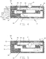
FIG. 4 is a fragmentary cross-sectional view of a microfluidic device containing a recirculating pump using a check valve according to the present invention showing its activated state; -
FIG. 5 is a view ofFIG. 4 with the pump bellows in its relaxed position; -
FIG. 6 is a top view of a recirculating system within a microfluidic device which includes check valves according to the present invention; -
FIG. 7 is a perspective view of another embodiment of an elastomeric check valve according to the present invention; -
FIG. 8 is a top view, partly in phantom, of the valve shown inFIG. 7 ; -
FIG. 9 is a side view, shown in cross-section, of the valve shown inFIG. 7 ; -
FIG. 10 is an end view, shown in cross-section, of the valve shown inFIG. 7 in its unactivated state; -
FIG. 11 is an end view, shown in cross-section, of the valve shown inFIG. 7 in its activated state; and -
FIG. 12 is a top view of each of the individual layers of the valve shown inFIG. 7 . - Referring more particularly to
FIGS. 1A and 1B of the drawings, there is shown a microfluidic assembly, generally indicated at 10, which contains a check valve which embodies the principles of the present invention.FIG. 1A illustrates assembly 10 having atop layer 12, asecond layer 14, athird layer 16, andbottom layer 18. These layers are preferably formed from a thin flexible material such as MYLAR in the present embodiment, but could also be constructed from a more flexible material such as latex.Layers adhesive spacing sheets 20a-c.Layers adhesive spacing sheets 22a-c, whilelayers adhesive spacing sheets 24a-c.Assembly 10 shown inFIG. 1B only containslayers sheets 20a-c and 22 a-c respectively. Spacingsheets 20a-c, 22a-c, 24a-c are preferably constructed from a high performance adhesive such as ACA (Adhesive Carrier Adhesive) or PSA (Pressure Sensitive Adhesive) manufactured by 3M Company. InFIG. 1A , a firstmicrofluidic chamber 30 is formed bysheets 20a-c separating layers 12 and 14. InFIG. 1A , asecond microfluidics chamber 32 is formed withinassembly 10 betweenlayer 14 andlayer 18, whilechamber 32 is formed betweenlayers FIG. 1B .Chambers flexible valve flap 34 which is formed withinlayer 14 by anopening 35, and which contacts the underside ofsheet 20c.Flap 34 forms a one-way valve withinassembly 10 asflap 34 can be flexed away fromsheet 20c to create a passageway betweenchambers flap 34 cannot move in the opposite direction, therefore, forward pressure inchannel 30 opensflap 34, while higher pressure inchannel 32seals flap 34 againstsheet 20c. The direction of the flow pattern is shown by arrow A. - Devices such as
assembly 10 can allow the introduction of two fluids together while preventing reverse flow of either fluid into the supply channel of the other fluid. This is important for maintaining correct fluid ratios within mixing systems, and also prevents contamination of reagents with sample, and vice-versa. - Another primary application for check valves in microfluidic systems is in recirculating pumps. The utilization of the compliance of the thin film layer within a multilayer laminate microfluidic device to pressurize a volume encapsulated within a pump chamber controls flow within the pump structure.
- Referring now to
FIGS. 4 and 5 , recirculatingpump 38 contains the same structure as the basic device shown inFIG. 1 , havinglayers sheets 20a-c, 22a-c, 24a-c. A first check valve is created byflexible valve flap 34 formed from opening 35 inlayer 14 and which contacts the underside ofsheet 20c, while a second check valve is created by aflexible valve flap 40 formed from asecond opening 41 withinlayer 14 and which contacts the upper side ofsheet 22a.Chambers - To operate
pump 38, flexibletop layer 12 is depressed as shown at arrow B, preferably by the finger of the pump operator.Pump 38 can also be designed such that an external mechanical apparatus, such as a solenoid, piezoelectric device, or an air pressure source is used to depresslayer 12. Assuming that the fluid inchamber 30 is incompressible,valve flap 34 opens whilevalve flap 40 remains closed, and the volume inchamber 32 increases as fluid fromchamber 30 travels through opening 35 as shown by arrow C while,layer 18 flexes to the position shown at arrow D. In theory, the expansion ofchamber 32 will equal the compression ofchamber 30 in amplitude and volume, assuming that layers 12 and have an identical radius. - When
layer 12 is released, it returns to its initial at-rest position as shown by arrow E, andvalve flap 34 closes.Layer 18 also returns to its initial position, which forcesvalve flap 40 open, allowing fluid fromchamber 32 to flow back throughopening 41 intochamber 30 along the path shown by arrow F. The force exerted on the fluid by the relaxation oflayer 12 is equal to the force-deformingchamber 30 by depressinglayer 12. - Pumps such as
pump 38 are important in the design of microfluidic devices. The ability to keep fluids moving within a microfluidic structure is important for mixing and anti-sedimentation. The analysis of whole blood within a microfluidic structure may require cells to remain suspended within a reaction chamber or flow injector. Recirculation pumping is a means for maintaining suspension or particles within fluids. -
FIG. 6 shows the layout of a recirculating microfluidic design which includes check valves constructed according to the present invention. Referring now toFIG. 6 , there is shown amicrofluidic circuit 60 containing a recirculating pump using check valves 62. This circuit may be utilized to mix two fluids together in a precise ratio defined by the two microfluidics channel volumes in which these fluids are captured. Anoutlet line 64 and aninlet line 66 of the recirculating loop connect to a known fixed volume circuit. The circuit may be used to sense reaction, divert the mixed solution, or merely hold the necessary volume of reagent fluid to be mixed. - In operation,
inlet line 66 is coupled to a conventional two-way valve 68, which valve is connected to avalve 70 via a sample storage bychannel 72.Valve 70 is coupled toinlet check valve 62a of the present invention via apump feed channel 74.Valve 70 is also connected to asample port inlet 76 and areagent port inlet 78.Valve 68 is also coupled to avalve 80 via awaste connector channel 82, whilevalve 80 is also coupled to awaste channel 84. Finally, a pump bellows 86 couples checkvalves valve 62b is connected tooutlet line 64. - The process for loading and
recirculating circuit 60 is as follows:inlet 78 receives a feed of sample fluid to be analyzed.Valves channel 74 orinlet 66.Valve 80 remains open, allowing sample fluid to flow withinchannel 82 and out throughwaste channel 84. A reagent is then introduced throughinlet 78 tovalve 70. Asvalve 70 is closed, the reagent remains isolated from the sample fluid. Reagent fillspump feed channel 74 throughcheck valve 62a, pump bellows 86 and throughcheck valve 62b intooutlet line 64 into other circuitry, and back intocircuit 60 viainlet line 66 tovalve 68.Valve 68 is then opened whilevalve 70 is kept closed, thus forcing reagent out ofchannel 82 throughopen valve 80 and out throughwaste channel 84. This process traps a fixed volume of reagent withincircuit 60. - At this
point valve 80 is closed andvalves Bellows 86 is activated, forcing fluid out ofbellows 86 throughvalve 62b and into the compliance of outlet line 64 (and associated sensor circuitry) andinlet line 66. This pumping action ofbellows 86 forces checkvalve 62a closed.Bellows 86 is then released, and as the pressure is removed from the chamber ofbellows 86,check valve 62a now opens ascheck valve 62b closes, sweeping a pulsed volume of fluid into bellows 86. This process is then repeated multiple times, until mixing, dilution, or sensing is complete. - Another example of a check valve embodying the principles of the present invention is shown in
FIGS. 7-12 . Referring now toFIG. 7 , a check valve assembly, generally indicated at 100, is shown having a series oflaminated layers 102a-g, along with a pair ofchannels channel 104 exitingassembly 100 throughtop layer 102a andchannel 106 exitingassembly 100 throughbottom layer 102g.Top layer 102b contains anaperture 104b which is aligned withaperture 104a, along with acutout section 108 forming a channel betweenlayers Layer 102d contains anaperture 104d aligned withaperture 104c, anaperture 106c which is aligned withaperture 106c, and acutout section 112.Section 112 includes aregion 112d aligned withsection 110 oflayer 102c, and also contains anelastomeric insert 114 which is held captive withinsection 112 betweenlayers Insert 114 is preferably constructed from latex or another similar material.Layer 102e contains anaperture 104e aligned withaperture 104d, anaperture 106e aligned withaperture 106d, and anaperture 116 aligned withsection 112 oflayer 102d.Layer 102f contains anaperture 106f aligned withaperture 106e and acutout section 118 which is aligned at one end withaperture 116 oflayer 102e and at its other end withaperture 104e oflayer 102e. Finally,layer 102g contains an aperture 106g aligned with aperture 106fj oflayer 102f. -
Layers layers - Having described the elements of
valve assembly 100 of the present invention, the operation of the embodiment will now be described. Referring now toFIGS. 7 ,9, 10 and 11 , liquid pressure is applied inchannel 104 in the direction ofarrow J. Channel 104, which is formed byaperture cutout section 118 inlayer 102f. Liquid flows throughchannel 104, alongcutout channel section 118, and upward throughaperture 116 oflayer 102e, toelastomeric insert 114. A sufficient minimum liquid pressure causes insert 114 to stretch, as can be seen most clearly inFIG. 11 . When insert 114 stretches to the position shown inFIG. 11 , liquid travels throughregion 112d withinlayer 102d, throughsection 110, and intochannel section 108, as shown by arrow K inFIG. 9 , and finally intochannel 106, where it exitsvalve assembly 100. - If liquid pressure is applied in the reverse direction through
channels elastomeric insert 114 against the flat surface oflayer 102e, effecting a seal against the flow of the liquid. Thus, the elastic property ofinsert 114 allows for sealingvalve assembly 100 during reverse flow, as well as biasingvalve assembly 100 to a normally closed position when no pressure is present withinassembly 100.Insert 114 is biased to its open or operating position only where a minimum pressure is applied in the forward direction. - Another embodiment of this invention provides an array of the valves of the types described in
Figures 1-6 , andFigures 7-12 , respectively. Such an array of microfluidic check valves can be integrated into a cartridge constructed of multi-layer laminates, and can be used to control multiple parallel fluidic processes, or a single process at multiple locations in the microfluidic circuit. Such as system may have applications in drug discovery processes, or in the analysis of multiple samples. - While this invention has been shown and described in terms of a preferred embodiment, it will be understood that this invention is not limited to any particular embodiment and that changes and modifications may be made without departing from the true spirit and scope of the invention as defined in the appended claims.
Claims (18)
- A microfluidic structure (10), comprising:a first layer (12; 102g) having a top side and a bottom side;a second layer (14; 102d) of flexible material having a top side and a bottom side;a first spacing layer (20a-c;102e-f) contacting said bottom side of said first layer and said top side of said second layer for separating said first and second layers, forming a first microfluidic channel (30;118);a third layer (16;102a) having a top side and a bottom side;a second spacing layer (22a-c;102b-c) contacting said bottom side of said second layer (14) and said top side of said third layer (16) for separating said second and third layers (14, 16) forming a second microfluidic channel (32;108);wherein said second layer (14;102d) contains a first opening (35;112, 112d) forming a first actuator section (34;114) within said second layer (14;102d), said first actuator section being shiftable between a first unactuated position in contact with said first spacing layer (20a-c;102e-f) in which said first and second microfluidic channels (30, 32; 118, 108) are isolated from each other and a second actuated position in which said first and second microfluidic channels (30, 32;118, 108) are in fluid communication with each othercharacterized in thatthe first and third layer (12, 16; 102g; 102a) are made of a flexible material.
- The structure of claim 1, wherein said first spacing layer (20a-c) comprises a plurality of thin flexible materials.
- The structure of at least one of the preceding claims, wherein said first opening is a first slit (35) forming a first actuator section within said second layer, and wherein said second layer contains a second slit (4) forming a second actuator section (40) within said second layer, said second actuator section shiftable between a first unactuated position in contact with said second spacing layer (22a-c) in which said first and second channels (30, 32) are isolated from one another and a second actuated position in which said first and second channels (30, 32) are in fluid communication with each other, and wherein the structure further comprises;
activating means for shifting said first layer (12) to a first pumping position from its normal position;
whereby when said first layer (12) is shifted to said first pumping position, said first actuator section (34) is shifted to said second actuated position allowing fluid to flow from said first microfluidic channel (30) into said first microfluidic channel (30) into said second microfluidic channel (32) while said second actuator section (40) is in said first unactuated position. - The structure of claim 3, wherein when said first layer is shifted to said first pumping position, said third layer is shifted from a first unactuated position to a second actuated position.
- The structure of at least one of the preceding claims, wherein the volume of said first and second microfluidic channels (30, 32) is equal.
- The structure of claim 4 or 3, wherein when said first layer (12) returns from said first pumping position to its normal position, said first actuator section is shifted to its first unactuated position while said second actuator section (40) is shifted to its second actuated position, allowing fluid to flow from said second microfluidic channel (32) into said first microfluidic channel (30).
- The structure of at least one of the preceding claims, wherein said first and second layers (12, 14) are constructed from MYLAR.
- The structure of claim 3, wherein said activating means is located external to the structure.
- The pump of claim 3 or 8, wherein said activating means are manually depressible by an operator.
- The structure of claim 3 or at least one of the claims 8 and 9, wherein said activating means comprises an air pressure source.
- The structure of claim 3 or one of the claims 8-10, wherein said activating means comprises an electromagnetic force generating mechanism.
- The structure of claim 11, wherein said electromagnetic force generating mechanism comprises a solenoid.
- The structure of claim 3 or one of the claims 8-12, wherein said activating means comprises an electrostatic force generating mechanism.
- The structure of claim 13, wherein said electrostatic force generating means comprises a piezoelectric device.
- The structure of one of the preceding claims, the structure further comprising:a valve structure; whereinthe first microfluidic channel (30, 118) is an inlet channel formed within said valve structure;the second microfluidic channel (32, 108) is an outlet channel formed within said valve structure;the first actuator section (34, 114) separates said inlet and said outlet channels, and in the first unactuated position said inlet channel (30, 118) is isolated from said outlet channel (32, 108), and in the second actuated position said inlet and said outlet channels are in fluid communication with each other, whereby when a fluid is introduced into said inlet channel (30, 118), pressure within said inlet shifts said first actuator section (14, 114) from said first unactuated position to said second actuated position allowing fluid to flow from said inlet channel (30, 118) to said outlet channel (32, 108), and when a fluid is introduced into said outlet channel (32, 108), pressure holds said first actuator section (14, 114) in said first unactuated position, preventing flow between said inlet and outlet channels.
- The structure of at least one of the preceding claims 1 to 14, further comprising a plurality of openings within said second layer (14) and a plurality of said first and second microfluidic channels (30, 32) whereas said openings (35, 41) form a plurality of said actuator sections (34, 40) within said second layer (14), said actuator sections (34, 40) shiftable between a first unactuated position in contact with said first spacing layer (20a-c) such that said first and second microfluidic channels (30, 32) are isolated from each other and a second actuated position such that said plurality of said first and second microfluidic channels (30, 32) are in fluid communication with each other.
- The structure of claim 16, further comprising means to individually actuate said actuator sections (34, 40).
- The device of Claim 17, wherein said means to individually actuate said actuator sections (34, 40) is taken from a group consisting of hydraulic, mechanic, pneumatic, magnetic, and electrostatic actuators.
Applications Claiming Priority (5)
| Application Number | Priority Date | Filing Date | Title |
|---|---|---|---|
| US20687800P | 2000-05-24 | 2000-05-24 | |
| US206878P | 2000-05-24 | ||
| US09/677,250 US6431212B1 (en) | 2000-05-24 | 2000-10-02 | Valve for use in microfluidic structures |
| US677250 | 2000-10-02 | ||
| PCT/US2001/015791 WO2001089695A2 (en) | 2000-05-24 | 2001-05-16 | Valve for use in microfluidic structures |
Publications (2)
| Publication Number | Publication Date |
|---|---|
| EP1289658A2 EP1289658A2 (en) | 2003-03-12 |
| EP1289658B1 true EP1289658B1 (en) | 2017-07-12 |
Family
ID=26901747
Family Applications (1)
| Application Number | Title | Priority Date | Filing Date |
|---|---|---|---|
| EP01937440.4A Expired - Lifetime EP1289658B1 (en) | 2000-05-24 | 2001-05-16 | Valve for use in microfluidic structures |
Country Status (5)
| Country | Link |
|---|---|
| US (1) | US6431212B1 (en) |
| EP (1) | EP1289658B1 (en) |
| JP (1) | JP2003534504A (en) |
| CA (1) | CA2408353A1 (en) |
| WO (1) | WO2001089695A2 (en) |
Cited By (1)
| Publication number | Priority date | Publication date | Assignee | Title |
|---|---|---|---|---|
| EP3315198A1 (en) * | 2016-10-28 | 2018-05-02 | Sysmex Corporation | Liquid-sealed cartridge and liquid transfering method |
Families Citing this family (113)
| Publication number | Priority date | Publication date | Assignee | Title |
|---|---|---|---|---|
| US6210128B1 (en) * | 1999-04-16 | 2001-04-03 | The United States Of America As Represented By The Secretary Of The Navy | Fluidic drive for miniature acoustic fluidic pumps and mixers |
| NZ533466A (en) * | 1999-06-28 | 2005-10-28 | California Inst Of Techn | Microfabricated elastomeric valve and pump systems |
| SE9902474D0 (en) * | 1999-06-30 | 1999-06-30 | Amersham Pharm Biotech Ab | Polymer valves |
| US7351376B1 (en) | 2000-06-05 | 2008-04-01 | California Institute Of Technology | Integrated active flux microfluidic devices and methods |
| WO2002001081A2 (en) | 2000-06-23 | 2002-01-03 | Micronics, Inc. | Valve for use in microfluidic structures |
| AU2001273057A1 (en) * | 2000-06-27 | 2002-01-08 | Fluidigm Corporation | A microfluidic design automation method and system |
| US6627159B1 (en) * | 2000-06-28 | 2003-09-30 | 3M Innovative Properties Company | Centrifugal filling of sample processing devices |
| DE10041853C1 (en) * | 2000-08-25 | 2002-02-28 | Gmd Gmbh | Configurable microreactor network |
| WO2002055198A2 (en) * | 2000-11-06 | 2002-07-18 | Nanostream Inc | Microfluidic flow control devices |
| US8097471B2 (en) * | 2000-11-10 | 2012-01-17 | 3M Innovative Properties Company | Sample processing devices |
| US6699018B2 (en) * | 2001-04-06 | 2004-03-02 | Ngk Insulators, Ltd. | Cell driving type micropump member and method for manufacturing the same |
| AU2002239823B2 (en) * | 2001-01-08 | 2008-01-17 | President And Fellows Of Harvard College | Valves and pumps for microfluidic systems and method for making microfluidic systems |
| US20020098122A1 (en) * | 2001-01-22 | 2002-07-25 | Angad Singh | Active disposable microfluidic system with externally actuated micropump |
| KR100916074B1 (en) | 2001-03-09 | 2009-09-08 | 바이오마이크로 시스템즈, 인크. | Microfluidic Interface Methods to Arrays and Systems for Interfaces |
| US7280014B2 (en) | 2001-03-13 | 2007-10-09 | Rochester Institute Of Technology | Micro-electro-mechanical switch and a method of using and making thereof |
| EP1377821A2 (en) * | 2001-04-03 | 2004-01-07 | Micronics, Inc. | Pneumatic valve interface for use in microfluidic structures |
| EP1384022A4 (en) | 2001-04-06 | 2004-08-04 | California Inst Of Techn | AMPLIFICATION OF NUCLEIC ACID USING MICROFLUIDIC DEVICES |
| US6752601B2 (en) * | 2001-04-06 | 2004-06-22 | Ngk Insulators, Ltd. | Micropump |
| US6802342B2 (en) | 2001-04-06 | 2004-10-12 | Fluidigm Corporation | Microfabricated fluidic circuit elements and applications |
| US20020155010A1 (en) * | 2001-04-24 | 2002-10-24 | Karp Christoph D. | Microfluidic valve with partially restrained element |
| US7195393B2 (en) * | 2001-05-31 | 2007-03-27 | Rochester Institute Of Technology | Micro fluidic valves, agitators, and pumps and methods thereof |
| US7318912B2 (en) * | 2001-06-07 | 2008-01-15 | Nanostream, Inc. | Microfluidic systems and methods for combining discrete fluid volumes |
| US7378775B2 (en) | 2001-10-26 | 2008-05-27 | Nth Tech Corporation | Motion based, electrostatic power source and methods thereof |
| US7211923B2 (en) * | 2001-10-26 | 2007-05-01 | Nth Tech Corporation | Rotational motion based, electrostatic power source and methods thereof |
| WO2003037514A2 (en) * | 2001-10-30 | 2003-05-08 | The Texas A & M University System | Method and apparatus for temperature gradient microfluidics |
| US6554591B1 (en) * | 2001-11-26 | 2003-04-29 | Motorola, Inc. | Micropump including ball check valve utilizing ceramic technology and method of fabrication |
| US7498714B2 (en) * | 2003-09-24 | 2009-03-03 | Microfabrica Inc. | Multi-layer three-dimensional structures having features smaller than a minimum feature size associated with the formation of individual layers |
| US7674361B2 (en) * | 2003-09-24 | 2010-03-09 | Microfabrica Inc. | Micro-turbines, roller bearings, bushings, and design of hollow closed structures and fabrication methods for creating such structures |
| JP3721334B2 (en) * | 2002-02-01 | 2005-11-30 | 富士写真フイルム株式会社 | Receptor-ligand association reaction method and reactor used therefor |
| KR100438588B1 (en) * | 2002-03-14 | 2004-07-02 | 엘지전자 주식회사 | Extremely-fine-fluid control apparatus using magnetic force |
| US7312085B2 (en) | 2002-04-01 | 2007-12-25 | Fluidigm Corporation | Microfluidic particle-analysis systems |
| WO2003085379A2 (en) | 2002-04-01 | 2003-10-16 | Fluidigm Corporation | Microfluidic particle-analysis systems |
| US6976590B2 (en) | 2002-06-24 | 2005-12-20 | Cytonome, Inc. | Method and apparatus for sorting particles |
| US6808075B2 (en) | 2002-04-17 | 2004-10-26 | Cytonome, Inc. | Method and apparatus for sorting particles |
| US20070065808A1 (en) * | 2002-04-17 | 2007-03-22 | Cytonome, Inc. | Method and apparatus for sorting particles |
| US9943847B2 (en) | 2002-04-17 | 2018-04-17 | Cytonome/St, Llc | Microfluidic system including a bubble valve for regulating fluid flow through a microchannel |
| AU2003277853A1 (en) | 2002-06-24 | 2004-01-06 | Fluidigm Corporation | Recirculating fluidic network and methods for using the same |
| US7452509B2 (en) * | 2002-07-26 | 2008-11-18 | Applied Biosystems Inc. | Microfluidic device including displaceable material trap, and system |
| US7198759B2 (en) * | 2002-07-26 | 2007-04-03 | Applera Corporation | Microfluidic devices, methods, and systems |
| US7135147B2 (en) * | 2002-07-26 | 2006-11-14 | Applera Corporation | Closing blade for deformable valve in a microfluidic device and method |
| US7201881B2 (en) * | 2002-07-26 | 2007-04-10 | Applera Corporation | Actuator for deformable valves in a microfluidic device, and method |
| DE10234819A1 (en) * | 2002-07-31 | 2004-02-19 | Roche Diagnostics Gmbh | Test apparatus for blood, comprising compound body with test strip levels and transport channels to give complex tests in compact structure |
| US6874999B2 (en) * | 2002-08-15 | 2005-04-05 | Motorola, Inc. | Micropumps with passive check valves |
| CA2500283A1 (en) | 2002-09-25 | 2004-04-08 | California Institute Of Technology | Microfluidic large scale integration |
| US8871446B2 (en) | 2002-10-02 | 2014-10-28 | California Institute Of Technology | Microfluidic nucleic acid analysis |
| KR20040036173A (en) * | 2002-10-23 | 2004-04-30 | 김종원 | Micro Compressor Actuated by Piezoelectric Actuator |
| US7419638B2 (en) * | 2003-01-14 | 2008-09-02 | Micronics, Inc. | Microfluidic devices for fluid manipulation and analysis |
| US7097070B2 (en) * | 2003-08-15 | 2006-08-29 | Protedyne Corporation | Method and apparatus for handling small volume fluid samples |
| US7217582B2 (en) | 2003-08-29 | 2007-05-15 | Rochester Institute Of Technology | Method for non-damaging charge injection and a system thereof |
| US7287328B2 (en) | 2003-08-29 | 2007-10-30 | Rochester Institute Of Technology | Methods for distributed electrode injection |
| GB0327094D0 (en) * | 2003-11-21 | 2003-12-24 | Inverness Medical Switzerland | Laminated device |
| DE102005003965A1 (en) * | 2005-01-27 | 2006-08-10 | Ehrfeld Mikrotechnik Gmbh | Micro-mixer for precipitation and/or crystallization reactions comprises reverse flow prevention unit placed between mixing and reaction zone and at least one channel for introducing partial stream |
| US8581308B2 (en) | 2004-02-19 | 2013-11-12 | Rochester Institute Of Technology | High temperature embedded charge devices and methods thereof |
| DE102004033317A1 (en) * | 2004-07-09 | 2006-02-09 | Roche Diagnostics Gmbh | Analytical test element |
| US20060018795A1 (en) * | 2004-07-23 | 2006-01-26 | General Electric Company | Fabrication methods and multifunctional substrate materials for chemical and biological analysis in microfluidic systems |
| US7032608B2 (en) * | 2004-09-01 | 2006-04-25 | Harris Corporation | Microfluidic check-valve embedded in LCP |
| US7214874B2 (en) * | 2004-11-04 | 2007-05-08 | International Business Machines Corporation | Venting device for tamper resistant electronic modules |
| US9260693B2 (en) | 2004-12-03 | 2016-02-16 | Cytonome/St, Llc | Actuation of parallel microfluidic arrays |
| US7328882B2 (en) | 2005-01-06 | 2008-02-12 | Honeywell International Inc. | Microfluidic modulating valve |
| JP4638249B2 (en) * | 2005-02-02 | 2011-02-23 | 積水化学工業株式会社 | Microvalve flow rate adjustment method |
| US7618391B2 (en) * | 2005-04-20 | 2009-11-17 | Children's Medical Center Corporation | Waveform sensing and regulating fluid flow valve |
| US20060245933A1 (en) * | 2005-05-02 | 2006-11-02 | General Electric Company | Valve and pump for microfluidic systems and methods for fabrication |
| US20070042427A1 (en) * | 2005-05-03 | 2007-02-22 | Micronics, Inc. | Microfluidic laminar flow detection strip |
| US9056291B2 (en) | 2005-11-30 | 2015-06-16 | Micronics, Inc. | Microfluidic reactor system |
| US7763453B2 (en) | 2005-11-30 | 2010-07-27 | Micronics, Inc. | Microfluidic mixing and analytic apparatus |
| WO2007080850A1 (en) * | 2006-01-12 | 2007-07-19 | Sumitomo Bakelite Co., Ltd. | Passive one-way valve and micro fluid device |
| JP5254949B2 (en) | 2006-03-15 | 2013-08-07 | マイクロニクス, インコーポレイテッド | Integrated nucleic acid assay |
| US7569789B2 (en) * | 2006-03-16 | 2009-08-04 | Visiongate, Inc. | Cantilevered coaxial flow injector apparatus and method for sorting particles |
| EP2041573B1 (en) * | 2006-06-23 | 2019-09-04 | PerkinElmer Health Sciences, Inc. | Methods and devices for microfluidic point-of-care immunoassays |
| WO2008147382A1 (en) * | 2006-09-27 | 2008-12-04 | Micronics, Inc. | Integrated microfluidic assay devices and methods |
| US8133629B2 (en) * | 2007-03-21 | 2012-03-13 | SOCIéTé BIC | Fluidic distribution system and related methods |
| ES2504215T3 (en) * | 2007-03-21 | 2014-10-08 | SOCIéTé BIC | Fluid collector and procedure for it |
| US8679694B2 (en) * | 2007-03-21 | 2014-03-25 | Societe Bic | Fluidic control system and method of manufacture |
| US20090007969A1 (en) * | 2007-07-05 | 2009-01-08 | 3M Innovative Properties Company | Microfluidic actuation structures |
| EP2171420A1 (en) * | 2007-07-31 | 2010-04-07 | Micronics, Inc. | Sanitary swab collection system, microfluidic assay device, and methods for diagnostic assays |
| EP2280905B1 (en) * | 2008-04-11 | 2016-07-06 | Fluidigm Corporation | Multilevel microfluidic systems and methods |
| EP3002489B1 (en) * | 2008-05-16 | 2017-09-20 | President and Fellows of Harvard College | Valves and other flow control in fluidic systems including microfluidic systems |
| US8082810B2 (en) * | 2008-09-29 | 2011-12-27 | Ysi Incorporated | Microfluidic elastic micro-aliquotter |
| US8318439B2 (en) | 2008-10-03 | 2012-11-27 | Micronics, Inc. | Microfluidic apparatus and methods for performing blood typing and crossmatching |
| CN103341369B (en) * | 2008-10-28 | 2015-04-29 | 藤仓化成株式会社 | Liquid passage device and manufacturing method |
| US9132423B2 (en) | 2010-01-29 | 2015-09-15 | Micronics, Inc. | Sample-to-answer microfluidic cartridge |
| GB2509440B (en) * | 2011-10-25 | 2015-06-03 | Ibm | Microfluidic device with interconnects |
| JP6190822B2 (en) | 2012-01-09 | 2017-08-30 | マイクロニクス, インコーポレイテッド | Microfluidic reactor system |
| EP3427830B1 (en) | 2012-10-24 | 2021-06-23 | Genmark Diagnostics Inc. | Integrated multiplex target analysis |
| US20140322706A1 (en) | 2012-10-24 | 2014-10-30 | Jon Faiz Kayyem | Integrated multipelx target analysis |
| EP2931427B1 (en) | 2012-12-13 | 2022-02-09 | Siemens Healthineers Nederland B.V. | Fluidic system with fluidic stop |
| EP2935908B1 (en) | 2012-12-21 | 2019-08-14 | PerkinElmer Health Sciences, Inc. | Fluidic circuits and related manufacturing methods |
| WO2014100743A2 (en) | 2012-12-21 | 2014-06-26 | Micronics, Inc. | Low elasticity films for microfluidic use |
| EP2935559B1 (en) | 2012-12-21 | 2020-09-16 | PerkinElmer Health Sciences, Inc. | Fluorescence detection system |
| JP6351702B2 (en) | 2013-03-15 | 2018-07-04 | ジェンマーク ダイアグノスティクス, インコーポレイテッド | System, method and apparatus for operating a deformable fluid container |
| EP2994543B1 (en) | 2013-05-07 | 2018-08-15 | Micronics, Inc. | Device for preparation and analysis of nucleic acids |
| EP2994532B1 (en) | 2013-05-07 | 2017-11-15 | Micronics, Inc. | Methods for preparation of nucleic acid-containing samples using clay minerals and alkaline solutions |
| US10386377B2 (en) | 2013-05-07 | 2019-08-20 | Micronics, Inc. | Microfluidic devices and methods for performing serum separation and blood cross-matching |
| WO2014191831A2 (en) * | 2013-05-31 | 2014-12-04 | Avishay Bransky | Cartridge for preparing a sample fluid containing cells for analysis |
| JP6662776B2 (en) * | 2013-08-12 | 2020-03-11 | コーニンクレッカ フィリップス エヌ ヴェKoninklijke Philips N.V. | Microfluidic device using valve |
| US10132739B2 (en) * | 2013-10-01 | 2018-11-20 | Owl biomedical, Inc. | Particle manipulation system with out-of-plane channel and recovery algorithm |
| USD881409S1 (en) | 2013-10-24 | 2020-04-14 | Genmark Diagnostics, Inc. | Biochip cartridge |
| US9498778B2 (en) | 2014-11-11 | 2016-11-22 | Genmark Diagnostics, Inc. | Instrument for processing cartridge for performing assays in a closed sample preparation and reaction system |
| KR20170016915A (en) | 2014-06-11 | 2017-02-14 | 마이크로닉스 인코포레이티드. | Microfluidic cartridges and apparatus with integrated assay controls for analysis of nucleic acids |
| EP2962758B1 (en) * | 2014-07-01 | 2017-07-19 | ThinXXS Microtechnology AG | Flow cell having a storage space and a transport channel that can be opened at a predetermined breaking point |
| WO2016033455A1 (en) | 2014-08-29 | 2016-03-03 | The Arizona Board Of Regents On Behalf Of The University Of Arizona | Methods, devices, and systems for microfluidic stress emulation |
| US10005080B2 (en) | 2014-11-11 | 2018-06-26 | Genmark Diagnostics, Inc. | Instrument and cartridge for performing assays in a closed sample preparation and reaction system employing electrowetting fluid manipulation |
| US9598722B2 (en) | 2014-11-11 | 2017-03-21 | Genmark Diagnostics, Inc. | Cartridge for performing assays in a closed sample preparation and reaction system |
| JP5866470B1 (en) | 2015-05-01 | 2016-02-17 | 株式会社朝日Fr研究所 | Check valve and microchemical chip using the same |
| US9578735B2 (en) | 2015-07-13 | 2017-02-21 | International Business Machines Corporation | Embedded venting system |
| GB201704769D0 (en) | 2017-01-03 | 2017-05-10 | Illumina Inc | Flowcell cartridge with floating seal bracket |
| CN110997028B (en) * | 2017-02-22 | 2022-12-30 | 康奈尔大学 | Mechanical vacuum dressing for mechanical management, protection and aspiration of small incision wounds |
| EP3720518B1 (en) | 2017-12-06 | 2024-09-04 | Cornell University | Manually-operated negative pressure wound therapy (npwt) bandage with improved pump efficiency, automatic pressure indicator and automatic pressure limiter |
| CN108591609A (en) * | 2018-04-18 | 2018-09-28 | 昆明理工大学 | A kind of device controlling liquid communication based on magnetic micro-valve |
| CN108704681B (en) * | 2018-05-25 | 2021-10-01 | 辽宁工业大学 | A plug-in microfluidic chip stabilization device |
| AU2019378009A1 (en) * | 2018-11-16 | 2021-01-14 | Illumina, Inc. | Laminate fluidic circuit for a fluid cartridge |
| JP7445403B2 (en) | 2019-09-27 | 2024-03-07 | シスメックス株式会社 | Liquid sealed cartridge and liquid delivery method |
| WO2023019447A1 (en) * | 2021-08-17 | 2023-02-23 | 京东方科技集团股份有限公司 | Control valve structure and usage method therefor, microfluidic chip, and nucleic acid extraction device |
Citations (1)
| Publication number | Priority date | Publication date | Assignee | Title |
|---|---|---|---|---|
| WO2001025138A1 (en) * | 1999-10-04 | 2001-04-12 | Nanostream, Inc. | Modular microfluidic devices comprising sandwiched stencils |
Family Cites Families (17)
| Publication number | Priority date | Publication date | Assignee | Title |
|---|---|---|---|---|
| US2856955A (en) * | 1955-08-02 | 1958-10-21 | Winkelman James | Valve structure for aerators or the like |
| US3807444A (en) * | 1972-10-10 | 1974-04-30 | Ca Valve Ltd | Check valve |
| SE8801299L (en) | 1988-04-08 | 1989-10-09 | Bertil Hoeoek | MICROMECHANICAL ONE-WAY VALVE |
| US4951617A (en) * | 1989-09-22 | 1990-08-28 | Fred Linamen | Attachable intake valve assembly and method for using same |
| SE9100392D0 (en) | 1991-02-08 | 1991-02-08 | Pharmacia Biosensor Ab | A METHOD OF PRODUCING A SEALING MEANS IN A MICROFLUIDIC STRUCTURE AND A MICROFLUIDIC STRUCTURE COMPRISING SUCH SEALING MEANS |
| DE69213340T2 (en) | 1991-05-30 | 1997-03-27 | Hitachi Ltd | Valve and its use in a device made of semiconductor material |
| SG45214A1 (en) * | 1992-03-05 | 1998-01-16 | Joe Santa & Ass Pty Ltd | A pump control valve and diaphragm |
| SE501713C2 (en) | 1993-09-06 | 1995-05-02 | Pharmacia Biosensor Ab | Diaphragm-type valve, especially for liquid handling blocks with micro-flow channels |
| JPH0828449A (en) * | 1994-07-13 | 1996-01-30 | Toyota Autom Loom Works Ltd | Valve system of compressor |
| SE9502258D0 (en) | 1995-06-21 | 1995-06-21 | Pharmacia Biotech Ab | Method for the manufacture of a membrane-containing microstructure |
| US5542821A (en) * | 1995-06-28 | 1996-08-06 | Basf Corporation | Plate-type diaphragm pump and method of use |
| US5899218A (en) * | 1995-06-28 | 1999-05-04 | Basf Corporation | Plate-type valve and method of use |
| DE19534378C1 (en) * | 1995-09-15 | 1997-01-02 | Inst Mikro Und Informationstec | Fluid pump for liquids and gases |
| US6068751A (en) | 1995-12-18 | 2000-05-30 | Neukermans; Armand P. | Microfluidic valve and integrated microfluidic system |
| US5971355A (en) | 1996-11-27 | 1999-10-26 | Xerox Corporation | Microdevice valve structures to fluid control |
| DE19720482C5 (en) | 1997-05-16 | 2006-01-26 | INSTITUT FüR MIKROTECHNIK MAINZ GMBH | Micro diaphragm pump |
| US5932799A (en) | 1997-07-21 | 1999-08-03 | Ysi Incorporated | Microfluidic analyzer module |
-
2000
- 2000-10-02 US US09/677,250 patent/US6431212B1/en not_active Expired - Lifetime
-
2001
- 2001-05-16 EP EP01937440.4A patent/EP1289658B1/en not_active Expired - Lifetime
- 2001-05-16 WO PCT/US2001/015791 patent/WO2001089695A2/en not_active Ceased
- 2001-05-16 CA CA 2408353 patent/CA2408353A1/en not_active Abandoned
- 2001-05-16 JP JP2001585927A patent/JP2003534504A/en not_active Withdrawn
Patent Citations (1)
| Publication number | Priority date | Publication date | Assignee | Title |
|---|---|---|---|---|
| WO2001025138A1 (en) * | 1999-10-04 | 2001-04-12 | Nanostream, Inc. | Modular microfluidic devices comprising sandwiched stencils |
Cited By (1)
| Publication number | Priority date | Publication date | Assignee | Title |
|---|---|---|---|---|
| EP3315198A1 (en) * | 2016-10-28 | 2018-05-02 | Sysmex Corporation | Liquid-sealed cartridge and liquid transfering method |
Also Published As
| Publication number | Publication date |
|---|---|
| JP2003534504A (en) | 2003-11-18 |
| WO2001089695A3 (en) | 2002-05-02 |
| WO2001089695A2 (en) | 2001-11-29 |
| CA2408353A1 (en) | 2001-11-29 |
| EP1289658A2 (en) | 2003-03-12 |
| US6431212B1 (en) | 2002-08-13 |
Similar Documents
| Publication | Publication Date | Title |
|---|---|---|
| US6431212B1 (en) | Valve for use in microfluidic structures | |
| EP2665956B1 (en) | Micro-pump or normally-off micro-valve | |
| US6581899B2 (en) | Valve for use in microfluidic structures | |
| US20050205816A1 (en) | Pneumatic valve interface for use in microfluidic structures | |
| US6644944B2 (en) | Uni-directional flow microfluidic components | |
| US12372168B2 (en) | Multifunctional microvalve capable of controlling flow of fluid, microfluidic chip and method | |
| US7942160B2 (en) | Valves and pumps for microfluidic systems and method for making microfluidic systems | |
| US7052594B2 (en) | Devices and methods for controlling fluid flow using elastic sheet deflection | |
| US20020155010A1 (en) | Microfluidic valve with partially restrained element | |
| US8309039B2 (en) | Valve structure for consistent valve operation of a miniaturized fluid delivery and analysis system | |
| AU2012208527A1 (en) | Micro-pump or normally-off micro-valve | |
| US20050047967A1 (en) | Microfluidic component providing multi-directional fluid movement | |
| EP3033526B1 (en) | Microfluidic device with valve | |
| Yuen et al. | Semi-disposable microvalves for use with microfabricated devices or microchips | |
| US20080160603A1 (en) | Flow stabilization in micro-and nanofluidic devices | |
| CN119267172B (en) | Pressing pump and microfluidic chip | |
| CN218523043U (en) | Micro valve structure | |
| WO2025166247A1 (en) | Embedded valve for microfluidic devices | |
| Saika et al. | Direct Liquid Manipulation by Parallel Micro Syringe System for High Controllability with Pico-Liter Scale |
Legal Events
| Date | Code | Title | Description |
|---|---|---|---|
| PUAI | Public reference made under article 153(3) epc to a published international application that has entered the european phase |
Free format text: ORIGINAL CODE: 0009012 |
|
| 17P | Request for examination filed |
Effective date: 20021106 |
|
| AK | Designated contracting states |
Kind code of ref document: A2 Designated state(s): AT BE CH CY DE DK ES FI FR GB GR IE IT LI LU MC NL PT SE TR |
|
| RIN1 | Information on inventor provided before grant (corrected) |
Inventor name: HAYENGA, JON, W. Inventor name: WILLIAMS, CLINTON, L. |
|
| 17Q | First examination report despatched |
Effective date: 20040902 |
|
| 17Q | First examination report despatched |
Effective date: 20040902 |
|
| GRAP | Despatch of communication of intention to grant a patent |
Free format text: ORIGINAL CODE: EPIDOSNIGR1 |
|
| RIC1 | Information provided on ipc code assigned before grant |
Ipc: B01L 7/00 20060101ALI20161111BHEP Ipc: G01N 35/10 20060101ALI20161111BHEP Ipc: B01L 3/00 20060101AFI20161111BHEP Ipc: B01F 13/00 20060101ALI20161111BHEP Ipc: B01F 5/00 20060101ALI20161111BHEP Ipc: B01D 11/00 20060101ALI20161111BHEP Ipc: F16K 99/00 20060101ALI20161111BHEP |
|
| INTG | Intention to grant announced |
Effective date: 20161206 |
|
| GRAS | Grant fee paid |
Free format text: ORIGINAL CODE: EPIDOSNIGR3 |
|
| GRAA | (expected) grant |
Free format text: ORIGINAL CODE: 0009210 |
|
| AK | Designated contracting states |
Kind code of ref document: B1 Designated state(s): AT BE CH CY DE DK ES FI FR GB GR IE IT LI LU MC NL PT SE TR |
|
| REG | Reference to a national code |
Ref country code: GB Ref legal event code: FG4D |
|
| REG | Reference to a national code |
Ref country code: CH Ref legal event code: EP |
|
| REG | Reference to a national code |
Ref country code: AT Ref legal event code: REF Ref document number: 907828 Country of ref document: AT Kind code of ref document: T Effective date: 20170715 |
|
| REG | Reference to a national code |
Ref country code: IE Ref legal event code: FG4D |
|
| REG | Reference to a national code |
Ref country code: DE Ref legal event code: R096 Ref document number: 60150513 Country of ref document: DE |
|
| REG | Reference to a national code |
Ref country code: NL Ref legal event code: MP Effective date: 20170712 |
|
| REG | Reference to a national code |
Ref country code: AT Ref legal event code: MK05 Ref document number: 907828 Country of ref document: AT Kind code of ref document: T Effective date: 20170712 |
|
| PG25 | Lapsed in a contracting state [announced via postgrant information from national office to epo] |
Ref country code: FI Free format text: LAPSE BECAUSE OF FAILURE TO SUBMIT A TRANSLATION OF THE DESCRIPTION OR TO PAY THE FEE WITHIN THE PRESCRIBED TIME-LIMIT Effective date: 20170712 Ref country code: AT Free format text: LAPSE BECAUSE OF FAILURE TO SUBMIT A TRANSLATION OF THE DESCRIPTION OR TO PAY THE FEE WITHIN THE PRESCRIBED TIME-LIMIT Effective date: 20170712 Ref country code: NL Free format text: LAPSE BECAUSE OF FAILURE TO SUBMIT A TRANSLATION OF THE DESCRIPTION OR TO PAY THE FEE WITHIN THE PRESCRIBED TIME-LIMIT Effective date: 20170712 Ref country code: SE Free format text: LAPSE BECAUSE OF FAILURE TO SUBMIT A TRANSLATION OF THE DESCRIPTION OR TO PAY THE FEE WITHIN THE PRESCRIBED TIME-LIMIT Effective date: 20170712 |
|
| PG25 | Lapsed in a contracting state [announced via postgrant information from national office to epo] |
Ref country code: GR Free format text: LAPSE BECAUSE OF FAILURE TO SUBMIT A TRANSLATION OF THE DESCRIPTION OR TO PAY THE FEE WITHIN THE PRESCRIBED TIME-LIMIT Effective date: 20171013 Ref country code: ES Free format text: LAPSE BECAUSE OF FAILURE TO SUBMIT A TRANSLATION OF THE DESCRIPTION OR TO PAY THE FEE WITHIN THE PRESCRIBED TIME-LIMIT Effective date: 20170712 |
|
| REG | Reference to a national code |
Ref country code: DE Ref legal event code: R097 Ref document number: 60150513 Country of ref document: DE |
|
| PG25 | Lapsed in a contracting state [announced via postgrant information from national office to epo] |
Ref country code: DK Free format text: LAPSE BECAUSE OF FAILURE TO SUBMIT A TRANSLATION OF THE DESCRIPTION OR TO PAY THE FEE WITHIN THE PRESCRIBED TIME-LIMIT Effective date: 20170712 |
|
| PLBE | No opposition filed within time limit |
Free format text: ORIGINAL CODE: 0009261 |
|
| STAA | Information on the status of an ep patent application or granted ep patent |
Free format text: STATUS: NO OPPOSITION FILED WITHIN TIME LIMIT |
|
| PG25 | Lapsed in a contracting state [announced via postgrant information from national office to epo] |
Ref country code: IT Free format text: LAPSE BECAUSE OF FAILURE TO SUBMIT A TRANSLATION OF THE DESCRIPTION OR TO PAY THE FEE WITHIN THE PRESCRIBED TIME-LIMIT Effective date: 20170712 |
|
| 26N | No opposition filed |
Effective date: 20180413 |
|
| REG | Reference to a national code |
Ref country code: DE Ref legal event code: R119 Ref document number: 60150513 Country of ref document: DE |
|
| REG | Reference to a national code |
Ref country code: CH Ref legal event code: PL |
|
| GBPC | Gb: european patent ceased through non-payment of renewal fee |
Effective date: 20180516 |
|
| REG | Reference to a national code |
Ref country code: BE Ref legal event code: MM Effective date: 20180531 |
|
| PG25 | Lapsed in a contracting state [announced via postgrant information from national office to epo] |
Ref country code: MC Free format text: LAPSE BECAUSE OF FAILURE TO SUBMIT A TRANSLATION OF THE DESCRIPTION OR TO PAY THE FEE WITHIN THE PRESCRIBED TIME-LIMIT Effective date: 20170712 |
|
| REG | Reference to a national code |
Ref country code: IE Ref legal event code: MM4A |
|
| PG25 | Lapsed in a contracting state [announced via postgrant information from national office to epo] |
Ref country code: LI Free format text: LAPSE BECAUSE OF NON-PAYMENT OF DUE FEES Effective date: 20180531 Ref country code: CH Free format text: LAPSE BECAUSE OF NON-PAYMENT OF DUE FEES Effective date: 20180531 |
|
| PG25 | Lapsed in a contracting state [announced via postgrant information from national office to epo] |
Ref country code: LU Free format text: LAPSE BECAUSE OF NON-PAYMENT OF DUE FEES Effective date: 20180516 |
|
| PG25 | Lapsed in a contracting state [announced via postgrant information from national office to epo] |
Ref country code: DE Free format text: LAPSE BECAUSE OF NON-PAYMENT OF DUE FEES Effective date: 20181201 Ref country code: FR Free format text: LAPSE BECAUSE OF NON-PAYMENT OF DUE FEES Effective date: 20180531 Ref country code: IE Free format text: LAPSE BECAUSE OF NON-PAYMENT OF DUE FEES Effective date: 20180516 Ref country code: GB Free format text: LAPSE BECAUSE OF NON-PAYMENT OF DUE FEES Effective date: 20180516 |
|
| PG25 | Lapsed in a contracting state [announced via postgrant information from national office to epo] |
Ref country code: BE Free format text: LAPSE BECAUSE OF NON-PAYMENT OF DUE FEES Effective date: 20180531 |
|
| PG25 | Lapsed in a contracting state [announced via postgrant information from national office to epo] |
Ref country code: TR Free format text: LAPSE BECAUSE OF FAILURE TO SUBMIT A TRANSLATION OF THE DESCRIPTION OR TO PAY THE FEE WITHIN THE PRESCRIBED TIME-LIMIT Effective date: 20170712 |
|
| PG25 | Lapsed in a contracting state [announced via postgrant information from national office to epo] |
Ref country code: PT Free format text: LAPSE BECAUSE OF FAILURE TO SUBMIT A TRANSLATION OF THE DESCRIPTION OR TO PAY THE FEE WITHIN THE PRESCRIBED TIME-LIMIT Effective date: 20170712 |
|
| PG25 | Lapsed in a contracting state [announced via postgrant information from national office to epo] |
Ref country code: CY Free format text: LAPSE BECAUSE OF FAILURE TO SUBMIT A TRANSLATION OF THE DESCRIPTION OR TO PAY THE FEE WITHIN THE PRESCRIBED TIME-LIMIT Effective date: 20170712 |