EP1289266A2 - Image processing method image processing apparatus and storage medium - Google Patents
Image processing method image processing apparatus and storage medium Download PDFInfo
- Publication number
- EP1289266A2 EP1289266A2 EP02255533A EP02255533A EP1289266A2 EP 1289266 A2 EP1289266 A2 EP 1289266A2 EP 02255533 A EP02255533 A EP 02255533A EP 02255533 A EP02255533 A EP 02255533A EP 1289266 A2 EP1289266 A2 EP 1289266A2
- Authority
- EP
- European Patent Office
- Prior art keywords
- density
- original
- input image
- histogram
- image
- Prior art date
- Legal status (The legal status is an assumption and is not a legal conclusion. Google has not performed a legal analysis and makes no representation as to the accuracy of the status listed.)
- Withdrawn
Links
Images








Classifications
-
- H—ELECTRICITY
- H04—ELECTRIC COMMUNICATION TECHNIQUE
- H04N—PICTORIAL COMMUNICATION, e.g. TELEVISION
- H04N1/00—Scanning, transmission or reproduction of documents or the like, e.g. facsimile transmission; Details thereof
- H04N1/40—Picture signal circuits
- H04N1/407—Control or modification of tonal gradation or of extreme levels, e.g. background level
- H04N1/4072—Control or modification of tonal gradation or of extreme levels, e.g. background level dependent on the contents of the original
- H04N1/4074—Control or modification of tonal gradation or of extreme levels, e.g. background level dependent on the contents of the original using histograms
-
- H—ELECTRICITY
- H04—ELECTRIC COMMUNICATION TECHNIQUE
- H04N—PICTORIAL COMMUNICATION, e.g. TELEVISION
- H04N1/00—Scanning, transmission or reproduction of documents or the like, e.g. facsimile transmission; Details thereof
- H04N1/40—Picture signal circuits
- H04N1/40062—Discrimination between different image types, e.g. two-tone, continuous tone
Definitions
- the present invention relates to an image processing apparatus and a processing method therefor, and more particularly to an image processing apparatus for classifying the input image and converting it into density characteristics suitable for the kind of the image, and a processing method therefor.
- a feature amount corresponding to the kind of the image is extracted and is evaluated by an evaluation function or a discrimination function determined in advance, thereby determining the kind of the image.
- the feature amount is often the generation frequently of black pixels or edges within a predetermined block area in the image, a histogram of the density levels, a spatial frequency distribution, or a directional distribution of lines.
- the filtering process is to enhance or improve a localized feature of the image thereby improving the image quality of the original image, and includes an integrating filter for alleviating noise texture, and a differential filter for enhancing the edges in the image thereby providing the image with a more vivid feeling.
- the ⁇ correction executes tonal correction for the image density.
- Examples of tonal correction for the image density include a process of uniformly extending or compressing the dynamic range of the density values, and a non-linear conversion of extending or compressing a particular density range in contrast to other ranges.
- the object of the present invention is to provide an image processing apparatus and a processing method therefor, capable of classifying the kind of the input image based on the feature of the input image, and effecting density correction according to each kind.
- an image processing method comprising the steps of:
- an image processing method comprising the steps of:
- an image processing method comprising the steps of:
- Fig. 1 is a block diagram showing the schematic configuration of an image reading apparatus embodying the present invention
- Fig. 2 is a cross-sectional view of the image reading apparatus embodying the present invention.
- an image sensor unit 101 irradiates an original 202 to be read, with the light from a light source.
- the light reflected from the original 202 is received through a lens 203 by an image pickup device 204, and is photoelectrically converted therein.
- the image sensor 101 is moved in the sub scanning direction along the original, and the color image is read in line-sequential manner of R, G and B colors for each line (or in point-sequential manner).
- the electrical signal obtained by photoelectric conversion in the image pickup device 204, is supplied to an electrical board 205 in an image reading apparatus 201.
- the electrical board 205 is provided with units 102 ⁇ 105 shown in Fig. 1 and executes following processes on the electrical signal supplied from the image sensor.
- An AFE 102 is an analog preprocessor for applying amplification, DC offset correction, A/D conversion etc. on the electrical signal outputted from the image sensor 101 to finally output digital image data for example of 12 bits.
- a shading correction circuit 103 stores a reference level data prepared by reading a reference white board provided outside the original reading area with the image sensor 101, as shading correction data, and executes shading correction on the image data generated by reading the read original, utilizing such correction data.
- the shading correction data are stored, after the acquisition thereof, in an external memory apparatus 106, and the data required in the scanning operation are downloaded to the image reading apparatus of the present embodiment.
- a data processing circuit 104 executes for example a packing process according to an image reading mode (for example binary or 24-bit multivalue) designated in advance from an external apparatus 106.
- an image reading mode for example binary or 24-bit multivalue
- An interface circuit 105 executes exchange of control signals with or outputs an image signal to the external apparatus 106 such as a personal computer, constituting the host apparatus of the image reading apparatus of the present embodiment.
- An external apparatus 106 is composed of a host computer, and is provided with a scanner driver for controlling the image reading apparatus.
- the external apparatus 106 and the image reading apparatus integrally constitute an image processing system.
- the scanner driver is provided with a user interface for instructing the image reading mode, resolution, image reading area etc. and transmits control signals or a reading start command etc. based on such the instruction to the image reading apparatus through the interface circuit 105.
- the scanner driver also executes an image display, by processing in succession the image data read by the image reading apparatus according to the control signal. In such operation, the scanner driver executes a gamma correction process of the present embodiment.
- the image processing apparatus of the present embodiment is provided with a function of discriminating, based on a preview image read with a low resolution, the kind of the original image as one of text original, photograph original and another original, then operating a density conversion table (hereinafter called ⁇ table) prepared for each kind of the original, and optimizing the density of a main scan image to be read subsequently.
- ⁇ table a density conversion table
- Fig. 3 is a flow chart showing the schematic process sequence of the image processing apparatus of the present embodiment, and such process sequence will be explained in the following with reference to this flow chart.
- the image processing apparatus receives a preview image of a relatively low resolution, read for example with the image reading apparatus, and also receives, at the same time, a position on the preview image of a main scan reading area to be finally stored (step S301).
- the image processing apparatus discriminates, by an image kind discriminating procedure to be explained later in more details, the kind of image of the designated reading area on the preview image as either one of text original, photograph original and another original (step S302).
- the discrimination is judged impossible.
- the density distribution of the original is not adjusted and there is prepared a through ⁇ -table (steps S303, S305). In such through ⁇ -table, the input values directly become the output values.
- step S304 In the discrimination of the kind of the image is completed in normal manner (step S304), there is executed an operation of generating a ⁇ -table according to the result of such discrimination and the density distribution within the designated area in the preview image (step S306, S307, S308). The details of this operation will be explained later.
- the ⁇ -table calculated from the image kind of the preview image and the density distribution, is used for executing density conversion of the preview image (step S309), and an image showing the result of such correction is displayed to the operator (step S310). If the image satisfies the intention of the operator, the sequence proceeds to a request for the main scan data, but, if necessary, there is executed a fine adjustment of the ⁇ -table (step S312) and the preview image display is renewed again (step S310) to await a further instruction of the operator (step S311).
- the image reading apparatus reads the original with a resolution instructed by the operator (step S310, main scanning operation).
- the image processing apparatus executes optimization of the density distribution, utilizing the ⁇ -table established in advance, thereby preparing image data subjected to adjustment of density gradation optimum to the content of the original image (step S314).
- the optimization of the density distribution of the main scan image based on the ⁇ -table is executed by the image processing apparatus, but, if the image reading apparatus is equipped with the ⁇ -table and is capable of executing the density conversion process, there can also be adopted a configuration in which the ⁇ -table is transferred from the image processing apparatus to the image reading apparatus prior to the main scanning operation and the optimization of density distribution is executed in the image reading apparatus.
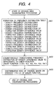
- Fig. 4 is a flow chart showing the original kind discrimination process of the image processing apparatus of the present embodiment.
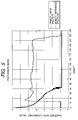
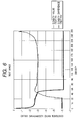
- Figs. 5 and 6 show the density frequency distribution (0 corresponding to black and 255 corresponding to white) of R color in a photograph image and a text image, and the frequency distribution of the density difference of R color to the adjacent pixel in the X-direction (horizontal direction of the image).
- the abscissa represents the density of each pixel for the density frequency distribution represented by a thin line, and the absolute value of the density difference for the frequency distribution of the density difference represented by a thick line.
- the ordinate indicates the ratio of the frequency relative to the total pixel number in logarithmic scale with a base of 10.
- pixels having a density value of -3 on the ordinate represent 0.1 % of the total pixels.
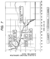
- Fig. 7 illustrates a procedure, in an example of frequency distribution of an image in which photograph and text are mixed, of calculating a feature amount KRX from the frequency distribution of the density difference in R color from the adjacent pixel in the X-direction.
- the image kind discrimination process calculates the frequency distribution of density for each color, and also calculates the density difference between the pixels adjacent in the vertical direction (Y-direction) or in the horizontal direction (X-direction), thereby obtaining the frequency distribution of the density difference (step S401).
- the frequency of a density difference 0 is doubled. Since the density difference is calculated by the absolute value, so that the density difference of 1 or larger includes the density changes both in the positive and negative directions. In comparison, the probability of a density difference 0 becomes 1/2, and the above-mentioned doubling operation intends a correction for such difference in the probability.
- the frequency of the density difference monotonously decreases with the increase in the density difference
- a text original as shown in Fig. 6, there exists a range in which the frequency of the density difference remains almost same regardless of the density difference (a substantially horizontal portion in the thick-lined curve).
- the present original kind discrimination process utilizing the above-described feature in the frequency distribution of the density difference, approximates the central portion of such frequency distribution of density difference by a first-order function and adopts the inclination thereof as a feature amount parameter.
- the operation procedure will be explained in the following with reference to Fig. 7.
- first-order functions representing the features of the density difference frequency distributions are calculated utilizing the density difference frequency distribution in the Y-direction and those of G and B colors to obtain inclination coefficients KRX, KGX, KBX, KRY, KGY, KBY (step S402).
- the kind of the original is discriminated utilizing the feature amount parameters calculated in the above-explained procedure and referring to predetermined plural discrimination criteria (step S403).
- the discrimination criteria :
- the original is discriminated as a photograph original if:
- the original is discriminated as a text original if:
- the original is discriminated as a text original if:
- the original is discriminated as another original if none of these discrimination criteria is met.
- Tp1, Tp2, Tt1 are constants determined experimentally in advance.
- the discrimination criterion 1 or 2 indicates the conditions that the feature amount parameters in all the colors and all the directions represent a photograph original or a text original. Also the discrimination criterion 3 provides composite conditions that none of the feature amount parameters is discriminated as a photograph original and any one of the colors is discriminated as a text original. This discrimination criterion is provided for detecting an original in which the text is represented in one color only, and the accuracy of discrimination can be improved by adding discrimination criteria according to the features of the existing originals.
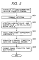
- Fig. 8 shows a routine for preparing gamma correction data for a text original, in the step S306 shown in Fig. 3.
- a step S805 executes synthesis with a monitoring gamma correction curve (Fig. 11), and stores the input/output table data as the text original gamma correction data in the external apparatus 6.
- the prepared text original gamma correction data are commonly used as the correction data for the color data of R, G and B colors.
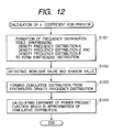
- Fig. 12 shows a routine for preparing gamma correction data for a photograph original, in the step S307 shown in Fig. 3.
- Fig. 13 shows a specific example of ⁇ coefficient calculation in case of an original having a certain density distribution.
- a step S1201 prepares density frequency distributions of the respective colors, and adds thus prepared density frequency distributions of the respective colors to obtain a synthesized frequency distribution of all the color components. It is assumed that the density values of the respective colors are in a color-balanced state.
- a step S1202 searches, from the side of the density 0 (namely black) in the synthesized density frequency distribution of all the colors, a minimum density value (hereinafter called shadow value) and a maximum density value (hereinafter called highlight value) at which the frequency distribution actually exists, and a step S1203 calculates the cumulative value of the frequencies of the respective densities, from the minimum value toward the maximum value, as a function of the density value. As a result, there is obtained a cumulative value h(d) as a function of the density value d.
- h'(d) in which a range less than the shadow value is normalized to 0 and a range equal to or higher than the highlight value is normalized to 255.
- the ⁇ -table based on thus obtained ⁇ -coefficient, generally assumes a form shown in Fig. 14 or in Fig. 15. For example, if the density distribution is heavily deviated toward the black side, there are obtained gamma characteristics as shown in Fig. 14 (gamma ⁇ 0.24), but, if the density distribution is somewhat deviated toward the white side, there are obtained gamma characteristics as shown in Fig. 15 (gamma ⁇ 1.6). Figs.
- the above-described algorithm of preparing the density conversion table allows to obtain a density conversion table capable of increasing the contrast of a density area (range) in which the frequency distribution is concentrated, thereby realizing conversion to an image with rectified gradation.
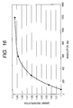
- Fig. 16 shows a ⁇ -coefficient reflection table for main scan in the present embodiment.
- This chart shows the experimentally determined change of ⁇ -magnification depending on the resolution, in reading a photograph original.
- the chart indicates, for example, the ⁇ -value optimum for a photograph original of a resolution of 600 dpi becomes 1/1.087 for a resolution of 1/8, or, stated differently, the optimum ⁇ -value form an image obtained by reading the original with a resolution of 75 dpi should be multiplied by 1.087 for obtaining the optimum ⁇ -value for original reading with 600 dpi.
- a ⁇ -table is prepared utilizing the ⁇ -coefficient G' for main scan in a similar manner as in the preparation of the preview ⁇ -table, and thus prepared ⁇ -table is used for executing the density conversion of the image read in the main scan to achieve optimum conversion of the density gradation optimum for the reading resolution.
- Fig. 17 shows the density distribution of image data, obtained by reading an original same as in the case of Fig. 13 but with a resolution of 400 dpi which is higher than in the case of Fig. 13.
- the distribution has a ⁇ -value of 2.13 and lies within a range of density levels of 11 to 255.
- the distribution has a ⁇ -value of 1.99 and lies within a range of density levels of 31 to 255.
- the density distribution comes closer to the average value with the nearby pixel data, thus assuming a smoother histogram shape with a certain change in the distribution, in comparison with the density distribution of the main scan image as shown in Fig. 17.
- the optimum density conversion table varies according to the resolution, even for a same photograph original. More specifically, there are generated changes in the density range and in the frequency distribution.
- the total number of pixels in the pre-scan shown in Fig. 13 is about 540,000 based on the maximum value of the cumulative value, while that in the main scan shown in Fig. 17 is about 15,800,000 based on the maximum value of the cumulative value. It will therefore be understood that the data amount in pre-scan is reduced, to shorten reducing the process time, to about 1/29 of that in the main scan.
- the image processing apparatus of the present embodiment is capable of preparing a density conversion table optimum for the image and optimizing the density gradation, by determining the cumulative frequency distribution from the synthesized density frequency distribution in the designated area on the input original image, then calculating an exponential function approximating the cumulative frequency distribution, and calculating a ⁇ -coefficient corresponding to the designated main scanning resolution from the exponent of the exponential function.
- Fig. 18 shows a table expanded from the ⁇ -coefficient reflection table for main scan, for an original having a different feature.
- the curves for a photograph original and an illustrated original show the changes in ⁇ -magnification, depending on the experimentally determined resolution at the original reading. Since the illustrated original generally has a larger area consisting of a uniform color in comparison with the photograph original, the ⁇ -coefficient shows a smaller change in the transition toward the high resolution.
- such tables can be suitably selected for example in case the kind of the original is discriminated as an illustrated original (S108 in Fig. 3 in the above-described embodiment) or in case the operator enters that the original is an illustrated original.
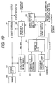
- Fig. 19 is a block diagram for facilitating the understanding of the present invention in the foregoing embodiment.
- image data from a scanner 900 are temporarily stored in a storage unit 901 composed of a large-capacity memory medium such as a hard disk.
- the stored data are entered into a density conversion unit 921, and to a block 910 for calculating a tone correction coefficient to be used in the density conversion executed in the density conversion unit 921.
- the output of the density conversion unit 921 is supplied to a display apparatus, or stored in a storage apparatus, or supplied to an output apparatus such as a printer.
- Blocks 910 to 913 process a pre-scan image obtained by pre-scan to obtain a tone correction coefficient suitable for the pre-scan image.
- the exponent of an approximation exponential function is finally obtained as a ⁇ -value indicating the tone correction coefficient.
- a block 910 receives the pre-scan image, determines the minimum and maximum values of the pixel data and calculates the density frequency distribution.
- the obtained minimum and maximum density values are supplied to a correction table preparation unit indicated by a block 920.
- the data of the density frequency distribution are subjected to the preparation of a cumulative frequency distribution in a block 911, and, since the minimum and maximum values of such cumulative frequency distribution are determined specifically for the original image and the pre-scan condition, there is prepared a cumulative frequency distribution normalized to a predetermined range, for example a range from a minimum value of 0 to a maximum value of 255.
- the data of such normalized cumulative frequency distribution are entered into an approximation level confirming block 913.
- the block 913 controls a block 912 for calculating an approximation exponential function and finally determines the exponent of the approximation exponential function, utilizing the least square method.
- the exponent from the block 912 is supplied, as the tone correction coefficient or ⁇ -coefficient, to a block 914 which corrects the ⁇ -coefficient obtained from the pre-scan image under fine adjustment according to the instruction from the operator as explained in the foregoing.
- the entered ⁇ -coefficient is transferred to the block 920 without change, and then is used for preparing the correction table, in this case a correction table for pre-scan image, based on the input data from the block 910 including the minimum and maximum values of the density values.
- the prepared correction table is transmitted to the block 921 for executing the density conversion of the pre-scan image therein.
- the data after the density conversion, in case of a pre-scan image, are transferred to the display apparatus to be presented to the operator.
- the operator observes the presented image, and, if necessary, manipulates the block 914 to execute fine adjustment of the ⁇ -coefficient value.
- the blocks 920, 921 are used for processing the pre-scan image.
- the blocks 910, 920, 921 executes a process on the main scan image.
- the ⁇ -coefficient for the pre-scan image, stored in the block 914 is the tone correction coefficient which has been confirmed for the pre-scan image by the operator on the display apparatus, or has been finally accepted by the operator after fine adjustment.
- Such tone correction coefficient ( ⁇ -coefficient) is entered into a block 930 for converting the ⁇ -coefficient for main scan, which also receives the resolution at the pre-scan operation, the resolution at the main scan operation and the information on the kind of the original, and is converted into a ⁇ -coefficient for main scan.
- the block 920 receives the ⁇ -coefficient from the block 930.
- the scanner 900 scans the original image under the condition for the main scan, and stores the main scan image in the storage unit 901. Thereafter the block 910 reads the data from the storage unit, then acquires the minimum and maximum values of the density level and transmits these data to the block 920, as in the pre-scan operation.
- the block 920 receives the minimum/maximum values from the block 910 and the main scan ⁇ -value from the block 930, the block 920 prepares a density correction table for density conversion of the main scan image.
- a density correction table is used in the block 921 for the density conversion of the main scan image, and the converted main scan image is outputted for example to the printer or the storage apparatus.
- the correction table is prepared in the following manner. For example, with the ⁇ -coefficient alone from the block 914 or the block 930, there can only be obtained the conversion characteristics as shown in Figs. 14 and 15. With such conversion characteristics, a density distribution for example within a density level range of 31 to 255 (in 8-bit presentation) as shown in Fig. 3 will be converted into a density range of about 110 to 255 in case of the conversion characteristics shown in Fig. 14 or into a density range of about 9 to 255 in case of the conversion characteristics shown in Fig. 15. The block 920 receives the minimum/maximum values in order to apply a curve as shown in Fig. 14 or Fig.
- the minimum density level for example level 31, can be converted into an output density level 0.
- the density range can be expanded in comparison with the case of no conversion. It is also possible to execute the conversion in such a manner that the minimum density level after the conversion becomes equal to that before the conversion.
- the density conversion of the main scan image is executed after the synthesis of the monitoring ⁇ -characteristics only in case of a text original, but a similar process is applicable also to a photograph original, and the density conversion may also be executed without the synthesis of the ⁇ -characteristics of a monitor device.
- the present invention can naturally be attained also by supplying a system or an apparatus with a memory medium storing program codes of a software realizing the functions of the aforementioned embodiments and causing a computer (or CPU or MPU) of such system or apparatus to read and execute the program codes stored in the memory medium.
- the program codes themselves read from the memory medium realize the novel functions of the present invention, and the memory medium storing the program codes constitutes the present invention.
- the memory medium for supplying the program codes can be, for example, a floppy disk, a hard disk, a magnetooptical disk, an optical disk, a CD-ROM, a CD-R, a magnetic tape, a non-volatile memory card or a ROM.
- the functions of the aforementioned embodiments can be realized not only in a case where the computer executes the read program codes but also a case where an operating system or the like functioning on the computer executes all the actual processes or a part thereof under the instructions of the program codes, thereby realizing the functions of the aforementioned embodiments.
- the functions of the aforementioned embodiments can also be realized in a case where the program codes read from the memory medium are once stored in a memory provided in a function expansion board inserted into the computer or a function expansion unit connected thereto, and a CPU or the like provided on such function expansion board or function expansion unit executes all the actual processes or a part thereof under the instructions of such program codes.
- the present invention is naturally further applicable to a case where the program codes realizing the novel functions of the aforementioned embodiments are distributed, from a memory medium storing such program codes, to a requesting person through a communication line.
Landscapes
- Engineering & Computer Science (AREA)
- Multimedia (AREA)
- Signal Processing (AREA)
- Facsimile Image Signal Circuits (AREA)
- Image Processing (AREA)
Abstract
Description
- a density histogram generation step of generating a density histogram from the input image;
- a density correction curve generation step of generating a density correction curve based on a ratio of the number of data close to the light and dark ends in the histogram to the total number of data in the histogram; and
- a density correction step of executing density correction on the input image, based on the density correction curve generated in the density correction curve generation step.
- a density histogram generation step of generating a density histogram from the input image;
- a cumulative histogram generation step of cumulating the frequency of density level values in an increasing direction of the density level value, taking the minimum density level value of data of the density histogram obtained in the density histogram generation step as a reference and starting point of cumulating operation, thereby obtaining a cumulative histogram indicating the relationship between the density level value and the cumulated value;
- a first γ value obtaining step of calculating an approximation exponential function approximating the density histogram and obtaining a first γ value indicating the density correction coefficient of the input image from the exponent of thus calculated function; and
- a first density correction step of executing a density correction process of the input image, based on the first γ value.
- Fig. 1 is a block diagram showing the configuration of an image reading apparatus embodying the present invention;
- Fig. 2 is a cross-sectional view of the image reading apparatus embodying the present invention;
- Fig. 3 is a flow chart showing the schematic process sequence of the image processing apparatus embodying the present invention;
- Fig. 4 is a flow chart showing an original kind discrimination process of the image processing apparatus embodying the present invention;
- Fig. 5 is a chart showing the frequency distribution of density of R color in a photograph image and the frequency distribution of density difference of R color between the adjacent pixels in the X-direction;
- Fig. 6 is a chart showing the frequency distribution of density of R color in a text image and the frequency distribution of density difference of R color between the adjacent pixels in the X-direction;
- Fig. 7 is a view illustrating the data processing in the image kind discrimination process in an embodiment of the present invention;
- Fig. 8 is a flow chart of preparing γ correction data for a text original in the image reading apparatus embodying the present invention;
- Fig. 9 is a view showing an example of the histogram of a text original image in an embodiment of the present invention;
- Fig. 10 is a view showing an example of a tone curve for a text original image in an embodiment of the present invention;
- Fig. 11 is a view showing an example of a tone curve of γ correction data for monitoring in an embodiment of the present invention;
- Fig. 12 is a flow chart showing a γ coefficient calculation process for preview in the image processing apparatus embodying the present invention;
- Fig. 13 is a view showing the outline of γ coefficient calculation process for preview in an embodiment of the present invention;
- Fig. 14 is a view showing an example of a γ table suitable for a photograph original and obtained in an embodiment of the present invention;
- Fig. 15 is a view showing another example of the γ table suitable for a photograph original and obtained in an embodiment of the present invention;
- Fig. 16 is a view showing a γ reflection table for main scanning in an embodiment of the present invention;
- Fig. 17 is a view showing the density frequency distribution and the cumulative frequency distribution of main scan input image data in an embodiment of the present invention;
- Fig. 18 is a view showing a table obtained by expanding the γ reflection table for main scanning in an embodiment of the present invention; and
- Fig. 19 is a block diagram showing a photograph original processing of an embodiment of the present invention.
and
Preview image γ-coefficient = (G^T), 0 < T < 1.0
The parameter T is to further control the level of density correction, in addition to the γ-coefficient calculated from the density distribution of the preview image. Such parameter T, in case of 1.0, provides a correction amount of zero by such parameter T, but provides a larger correction amount as the parameter T becomes closer to 0. In the entire correction amount, T = 1 provides the largest correction and corrects the density distribution of the original in most uniform manner, while T = 0.0 provides a zero correction amount and does not affect the input density distribution. The default value is T = 1. In such case, the density conversion table directly adopting the calculated γ-coefficient is prepared and used.
Claims (20)
- An image processing method comprising the steps of:detecting the density difference of each pixel in the input image from an adjacent pixel;generating a histogram of the density differences detected in said density difference detecting step;generating a function approximating the histogram generated in said histogram generation step; anddiscriminating the kind of said input image from the coefficient of the function generated in said approximation function generating step.
- A method according to claim 1, wherein said approximation function generation step includes:a logarithmic conversion step of converting the histogram generated in said histogram generation step into a logarithmically represented histogram; andan approximation first-order function generation step of generating a first-order function approximating the histogram converted into logarithmic representation in said logarithmic conversion step.
- A method according to claim 1, further comprising:a first density conversion step of applying a density conversion process corresponding to the result of discrimination in said image kind discrimination step, to said input image.
- A method according to claim 1, further comprising:a second density conversion step of applying a density conversion process corresponding to the result of discrimination in said image kind discrimination step, to an image obtained by reading an original of said input image, with a resolution different from that of said input image.
- A storage medium which stores a computer readable program for realizing an image processing method, the method comprising the steps of:detecting the density difference of each pixel in the input image from an adjacent pixel;generating a histogram of the density differences detected in said density difference detecting step;generating a function approximating the histogram generated in said histogram generation step; anddiscriminating the kind of said input image from the coefficient of the function generated in said approximation function generating step.
- An image processing apparatus comprising:a density difference detecting circuit, arranged to detect the density difference of each pixel in the input image from an adjacent pixel;a histogram generating circuit, arranged to generate a histogram of the density differences detected in said density difference detecting circuit;an approximation function generating circuit, arranged to generate a function approximating the histogram generated in said histogram generating circuit; andan image kind discriminating circuit, arranged to discriminate the kind of said input image from the coefficient of the function generated in said approximation function generating circuit.
- An image processing method comprising the steps of:wherein said text image density correction step includes:reading an original and generating input image data;calculating the sharpness of said input image from said input image data;discriminating whether the original is a text original or a photograph original from the sharpness of said input image; andapplying, in case said original kind discrimination step discriminates that said original is a text original, a density correction process to the input image obtained by reading said original;a density histogram generation step of generating a density histogram from said input image;a density correction curve generation step of generating a density correction curve based on a ratio of the number of data close to the light and dark ends in said histogram to the total number of data in said histogram; anda density correction step of executing density correction on said input image, based on the density correction curve generated in said density correction curve generation step.
- A method according to claim 7, wherein said density correction curve generation step divides the density into plural areas by taking a medium value of the shadow value and the highlight value of said image data as reference, and generates said density correction curve based on the number of data contained in each area.
- A method according to claim 8, wherein said density correction curve generation step generates an S-shaped density correction curve so as to make a signal of a density level darker than said medium value even darker and make a signal of a density level lighter than said medium value even lighter.
- A method according to claim 9, wherein said density correction curve generation step generates an S-shaped density correction curve of a smaller curvature in case said ratio of the number of data close to the light and dark ends is large, and an S-shaped density correction curve of a larger curvature in case said ratio is small.
- A method according to claim 7, wherein said density histogram generation step generates, in case said input image is a color image, a single density histogram by synthesizing the density data of R, G and B colors of said image data.
- A storage medium which stores a computer readable program for realizing an image processing method, the method comprising the steps of:wherein said text image density correction step includes:reading an original and generating input image data;calculating the sharpness of said input image from said input image data;discriminating whether the original is a text original or a photograph original from the sharpness of said input image; andapplying, in case said original kind discrimination step discriminates that said original is a text original, a density correction process to the input image obtained by reading said original;a density histogram generation step of generating a density histogram from said input image;a density correction curve generation step of generating a density correction curve based on a ratio of the number of data close to the light and dark ends in said histogram to the total number of data in said histogram; anda density correction step of executing density correction on said input image, based on the density correction curve generated in said density correction curve generation step.
- An image processing apparatus comprising:wherein said text image density correction curve generating circuit includes:an image reading circuit, arranged to read an original and generating input image data;an original kind discriminating circuit, arranged to discriminate whether said original is a text original or a photograph original from the sharpness of said input image;a text image density correction curve generating circuit, arranged to generate, in case said original kind discrimination circuit discriminates that said original is a text original, a text image density correction curve for applying a density correction process to the input image; anda text image density correction circuit, arranged to execute a density correction process of the input image obtained by reading said original, utilizing said text image density correction curve;a density histogram generation circuit, arranged to generate a density histogram from said input image;a density correction curve generation circuit, arranged to generate a density correction curve based on a ratio of the number of data close to the light and dark ends in said histogram to the total number of data in said histogram; anda density correction circuit, arranged to execute density correction on said input image, based on the density correction curve generated in said density correction curve generation circuit.
- An image processing method comprising the steps of:wherein said photograph image density correction step includes:reading an original with a first reading condition to generate input image data;calculating the sharpness of said input image from said input image;discriminating whether the kind of the original is a text original or a photograph original, based on the sharpness of said input image; andapplying, in case said original kind discrimination step discriminates that said original is a photograph original, a density correction process to the input image obtained by reading said original;a density histogram generation step of generating a density histogram from said input image;a cumulative histogram generation step of cumulating the frequency of density level values in an increasing direction of the density level value, taking the minimum density level value of data of the density histogram obtained in said density histogram generation step as a reference and starting point of cumulating operation, thereby obtaining a cumulative histogram indicating the relationship between the density level value and the cumulated value;a first γ value obtaining step of calculating an approximation exponential function approximating said density histogram and obtaining a first γ value indicating the density correction coefficient of the input image from the exponent of thus calculated function; anda first density correction step of executing a density correction process of said input image, based on said first γ value.
- A method according to claim 14, further comprising:a second image reading step of reading said original with a second reading condition different from said first reading condition, thereby generating second input image data;a γ value conversion step of converting said first γ value into a second γ value according to said first and second reading conditions; anda second density correction step of executing a density correction process on said second input image based on said second γ value.
- A method according to claim 14, further comprising:an image display output step of outputting the image processed in said first density correction step to a display unit;a density correction instruction input step of entering a density correction instruction input by an operation in response to an image displayed by said display output step;a second image reading step of reading said original with a second reading condition different from said first reading condition, thereby generating second input image data;a corrected γ value conversion step of converting said first γ value into a third γ value according to said first and second reading conditions and the entry of said density correction instruction; anda third density correction step of executing a density correction process on said second input image based on said corrected γ value.
- A method according to claim 16, wherein said corrected γ value conversion step executes conversion to the third γ value further according to the kind of the original.
- A storage medium which stores a computer readable program for realizing an image processing method, the method comprising the steps of:wherein said photograph image density correction step includes:reading an original to generate input image data;calculating the sharpness of said input image from said input image;discriminating whether the kind of the original is a text original or a photograph original, based on the sharpness of said input image; andapplying, in case said original kind discrimination step discriminates that said original is a photograph original, a density correction process to the input image obtained by reading said original;a density histogram generation step of generating a density histogram from said input image;a cumulative histogram generation step of cumulating the frequency of density level values in an increasing direction of the density level value, taking the minimum density level value of data of the density histogram obtained in said density histogram generation step as a reference and starting point of cumulating operation, thereby obtaining a cumulative histogram indicating the relationship between the density level value and the cumulated value;a γ value obtaining step of calculating an approximation exponential function approximating said density histogram and obtaining a γ value indicating the density correction coefficient of the input image from the exponent of thus calculated function; anda density correction step of executing a density correction process of said input image, based on said γ value.
- An image processing apparatus comprising:wherein said photograph image density correction circuit includes:an image reading apparatus, arranged to read an original to generate input image data;a sharpness calculation circuit, arranged to calculate the sharpness of said input image from said input image;an original kind discrimination circuit, arranged to discriminate whether the kind of the original is a text original or a photograph original, based on the sharpness of said input image; anda photograph image density correction circuit, arranged to apply, in case said original kind discrimination circuit discriminates that said original is a photograph original, a density correction process to the input image obtained by reading said original;a density histogram generation circuit, arranged to generate a density histogram from said input image;a cumulative histogram generation circuit, arranged to cumulate the frequency of density level values in an increasing direction of the density level value, taking the minimum density level value of data of the density histogram obtained in said density histogram generation circuit as a reference and starting point of cumulating operation, thereby obtaining a cumulative histogram indicating the relationship between the density level value and the cumulated value;a γ value obtaining circuit, arranged to calculate an approximation exponential function approximating said density histogram and obtaining a γ value indicating the density correction coefficient of the input image from the exponent of thus calculated function; anda density correction circuit, arranged to execute a density correction process of said input image, based on said γ value.
- A computer program storing processor implementable steps for performing a method according to any one of claims 1-4, 7-11 and 14-17.
Applications Claiming Priority (6)
| Application Number | Priority Date | Filing Date | Title |
|---|---|---|---|
| JP2001239139A JP2003051944A (en) | 2001-08-07 | 2001-08-07 | Image processing method, image processing system, program, and storage medium |
| JP2001239140 | 2001-08-07 | ||
| JP2001239140A JP4428895B2 (en) | 2001-08-07 | 2001-08-07 | Image processing apparatus, method, program, and recording medium |
| JP2001239139 | 2001-08-07 | ||
| JP2002005181 | 2002-01-11 | ||
| JP2002005181A JP4027098B2 (en) | 2002-01-11 | 2002-01-11 | Image processing apparatus and image processing method |
Publications (2)
| Publication Number | Publication Date |
|---|---|
| EP1289266A2 true EP1289266A2 (en) | 2003-03-05 |
| EP1289266A3 EP1289266A3 (en) | 2006-04-12 |
Family
ID=27347292
Family Applications (1)
| Application Number | Title | Priority Date | Filing Date |
|---|---|---|---|
| EP02255533A Withdrawn EP1289266A3 (en) | 2001-08-07 | 2002-08-07 | Image processing method image processing apparatus and storage medium |
Country Status (3)
| Country | Link |
|---|---|
| US (2) | US7016534B2 (en) |
| EP (1) | EP1289266A3 (en) |
| CN (1) | CN1203657C (en) |
Cited By (1)
| Publication number | Priority date | Publication date | Assignee | Title |
|---|---|---|---|---|
| WO2007024407A1 (en) * | 2005-08-24 | 2007-03-01 | Intel Corporation | Techniques to improve contrast enhancement using a luminance histogram |
Families Citing this family (31)
| Publication number | Priority date | Publication date | Assignee | Title |
|---|---|---|---|---|
| US7016534B2 (en) * | 2001-08-07 | 2006-03-21 | Canon Kabushiki Kaisha | Method, and apparatus for discriminating kind of image medium stored with program |
| DE60233676D1 (en) * | 2001-12-21 | 2009-10-22 | Canon Kk | |
| KR100490405B1 (en) * | 2002-07-02 | 2005-05-17 | 삼성전자주식회사 | Method for adjusting image color in printing system and graphical user interface therefor |
| US7595918B2 (en) * | 2002-08-27 | 2009-09-29 | Canon Kabushiki Kaisha | Transparent original reading apparatus and illuminating apparatus for reading apparatus |
| JP2004140802A (en) * | 2002-09-24 | 2004-05-13 | Ricoh Co Ltd | Image forming apparatus, printing method |
| US7403308B2 (en) * | 2002-11-14 | 2008-07-22 | Kabushiki Kaisha Toshiba | Image forming apparatus |
| US7307758B2 (en) * | 2002-11-14 | 2007-12-11 | Kabushiki Kaisha Toshiba | Image forming apparatus and image forming method |
| JP4241084B2 (en) * | 2003-02-24 | 2009-03-18 | キヤノン株式会社 | Image reading device |
| JP4332443B2 (en) * | 2003-03-07 | 2009-09-16 | キヤノン株式会社 | Image reading apparatus and image forming apparatus |
| JP4172346B2 (en) * | 2003-07-15 | 2008-10-29 | コニカミノルタビジネステクノロジーズ株式会社 | Image processing apparatus and program |
| US20050168595A1 (en) * | 2004-02-04 | 2005-08-04 | White Michael F. | System and method to enhance the quality of digital images |
| JP4033198B2 (en) * | 2004-02-27 | 2008-01-16 | カシオ計算機株式会社 | Image processing apparatus, image projection apparatus, image processing method, and program |
| JP2005260405A (en) * | 2004-03-10 | 2005-09-22 | Matsushita Electric Ind Co Ltd | Image processing apparatus and image processing method |
| JP4165428B2 (en) * | 2004-03-30 | 2008-10-15 | セイコーエプソン株式会社 | Image processing apparatus, image processing method, computer program for performing image processing, recording medium for recording computer program, and projector |
| JP2005348237A (en) * | 2004-06-04 | 2005-12-15 | Brother Ind Ltd | Image density adjusting apparatus and image reading apparatus provided with the apparatus |
| JP4498149B2 (en) * | 2005-01-17 | 2010-07-07 | キヤノン株式会社 | Image reading device |
| US7454058B2 (en) * | 2005-02-07 | 2008-11-18 | Mitsubishi Electric Research Lab, Inc. | Method of extracting and searching integral histograms of data samples |
| JP2007067571A (en) * | 2005-08-29 | 2007-03-15 | Fujitsu Ltd | Image processing device |
| JP4791861B2 (en) * | 2006-03-10 | 2011-10-12 | 株式会社リコー | Image transmitting apparatus, control method thereof, and program |
| US8014602B2 (en) * | 2006-03-29 | 2011-09-06 | Seiko Epson Corporation | Backlight image determining apparatus, backlight image determining method, backlight image correction apparatus, and backlight image correction method |
| US7916943B2 (en) * | 2006-06-02 | 2011-03-29 | Seiko Epson Corporation | Image determining apparatus, image determining method, image enhancement apparatus, and image enhancement method |
| US7916942B1 (en) * | 2006-06-02 | 2011-03-29 | Seiko Epson Corporation | Image determining apparatus, image enhancement apparatus, backlight image enhancement apparatus, and backlight image enhancement method |
| US8125569B2 (en) * | 2008-12-03 | 2012-02-28 | Sony Corporation | Dynamic contrast on displays using average picture level and histogram analysis |
| JP4692641B2 (en) * | 2009-01-21 | 2011-06-01 | 富士ゼロックス株式会社 | Image forming apparatus and image forming program |
| US20120019841A1 (en) * | 2010-07-20 | 2012-01-26 | Schaertel David M | Document scanner |
| KR20120070255A (en) * | 2010-12-21 | 2012-06-29 | 삼성전자주식회사 | Image scanning apparatus and circuit board in image scanning apparatus |
| JP5745889B2 (en) * | 2011-02-22 | 2015-07-08 | 理想科学工業株式会社 | Image data generation apparatus and image data generation method |
| JP5819897B2 (en) | 2013-09-10 | 2015-11-24 | 株式会社Screenホールディングス | Imaging system and imaging method |
| JP6161484B2 (en) * | 2013-09-19 | 2017-07-12 | 株式会社Pfu | Image processing apparatus, image processing method, and computer program |
| CN106400203A (en) * | 2016-08-26 | 2017-02-15 | 宜兴润德纺织品制造有限公司 | Heat-resistant fiber applied to textile cloth knitting, and preparation method thereof |
| JP7584975B2 (en) | 2020-09-29 | 2024-11-18 | キヤノン株式会社 | Image reader |
Family Cites Families (22)
| Publication number | Priority date | Publication date | Assignee | Title |
|---|---|---|---|---|
| CA1226976A (en) * | 1984-03-30 | 1987-09-15 | Nobuyoshi Nakajima | Method and apparatus for automatically correcting subtraction image density |
| DE3802681C2 (en) * | 1987-01-30 | 1997-01-09 | Fuji Photo Film Co Ltd | Method for classifying color templates and device therefor |
| JPH0642882B2 (en) * | 1987-04-20 | 1994-06-08 | 富士写真フイルム株式会社 | Desired image signal range determination method |
| EP0352491B1 (en) * | 1988-06-30 | 1996-08-14 | Dainippon Screen Mfg. Co., Ltd. | Method of generating gradation correction curve for correcting gradation character of image |
| JPH02253765A (en) * | 1989-03-28 | 1990-10-12 | Toshiba Corp | Picture processor |
| US6009193A (en) * | 1990-05-16 | 1999-12-28 | Canon Kabushiki Kaisha | Method and apparatus for converting N-value image to M-value image, for < NM |
| IL101029A (en) * | 1992-02-20 | 1996-01-19 | Scitex Corp Ltd | Method for identifying film type |
| JP3164744B2 (en) * | 1994-12-21 | 2001-05-08 | 株式会社東芝 | Image forming device |
| JPH08235355A (en) * | 1995-02-28 | 1996-09-13 | Minolta Co Ltd | Picture processor |
| DE19531390A1 (en) * | 1995-08-26 | 1997-02-27 | Hell Ag Linotype | Method and device for converting color values |
| JP3335830B2 (en) * | 1995-12-28 | 2002-10-21 | シャープ株式会社 | Image processing device |
| JP3280888B2 (en) * | 1996-08-19 | 2002-05-13 | 三星電子株式会社 | Image quality improvement method and circuit using quantized average-matching histogram equalization |
| JP3852998B2 (en) * | 1996-12-25 | 2006-12-06 | シャープ株式会社 | Image processing device |
| JPH10271326A (en) * | 1997-03-21 | 1998-10-09 | Sharp Corp | Image processing device |
| JP3425847B2 (en) * | 1997-04-25 | 2003-07-14 | 京セラミタ株式会社 | Image processing device |
| EP0933924B1 (en) * | 1998-01-28 | 2004-03-24 | Konica Corporation | Image processing apparatus |
| US6222642B1 (en) * | 1998-08-10 | 2001-04-24 | Xerox Corporation | System and method for eliminating background pixels from a scanned image |
| EP1079601B1 (en) * | 1999-03-05 | 2008-06-18 | Seiko Epson Corporation | Image data correcting device, image data correcting method, medium on which image data correcting program is recorded |
| JP2001094810A (en) * | 1999-09-22 | 2001-04-06 | Toshiba Tec Corp | Image processing method, image processing apparatus, and image forming apparatus |
| US7016534B2 (en) * | 2001-08-07 | 2006-03-21 | Canon Kabushiki Kaisha | Method, and apparatus for discriminating kind of image medium stored with program |
| US7016086B2 (en) * | 2001-08-07 | 2006-03-21 | Kabushiki Kaisha Toshiba | Image forming apparatus |
| KR20040048790A (en) * | 2002-12-03 | 2004-06-10 | 삼성전자주식회사 | Apparatus and Method for control luminance |
-
2002
- 2002-08-05 US US10/211,520 patent/US7016534B2/en not_active Expired - Lifetime
- 2002-08-05 CN CN02127606.4A patent/CN1203657C/en not_active Expired - Fee Related
- 2002-08-07 EP EP02255533A patent/EP1289266A3/en not_active Withdrawn
-
2005
- 2005-10-21 US US11/254,639 patent/US7113639B2/en not_active Expired - Lifetime
Cited By (3)
| Publication number | Priority date | Publication date | Assignee | Title |
|---|---|---|---|---|
| WO2007024407A1 (en) * | 2005-08-24 | 2007-03-01 | Intel Corporation | Techniques to improve contrast enhancement using a luminance histogram |
| GB2442409A (en) * | 2005-08-24 | 2008-04-02 | Intel Corp | Techniques to improve contrast enhancement using a luminance histogram |
| GB2442409B (en) * | 2005-08-24 | 2011-05-25 | Intel Corp | Techniques to improve contrast enhancement using a luminance histogram |
Also Published As
| Publication number | Publication date |
|---|---|
| US7113639B2 (en) | 2006-09-26 |
| US20060039604A1 (en) | 2006-02-23 |
| EP1289266A3 (en) | 2006-04-12 |
| CN1203657C (en) | 2005-05-25 |
| CN1402526A (en) | 2003-03-12 |
| US20030043410A1 (en) | 2003-03-06 |
| US7016534B2 (en) | 2006-03-21 |
Similar Documents
| Publication | Publication Date | Title |
|---|---|---|
| EP1289266A2 (en) | Image processing method image processing apparatus and storage medium | |
| US6359703B1 (en) | Image processing apparatus and method | |
| EP1505821B1 (en) | Image processing apparatus, an image forming apparatus and an image processing method | |
| US5339365A (en) | Image processing apparatus capable of using fuzzy logic | |
| US7940434B2 (en) | Image processing apparatus, image forming apparatus, method of image processing, and a computer-readable storage medium storing an image processing program | |
| US8170336B2 (en) | Image processing apparatus, image forming apparatus, image processing method and computer-readable recording medium | |
| US8203773B2 (en) | Image processing method, image processing apparatus, image forming apparatus, and recording medium for chromatic content determination | |
| US20010015815A1 (en) | Image forming apparatus which excels in reproducibility of colors, fine lines and gradations even in a copy made from a copied image | |
| JPH06121161A (en) | Character processing system for color image processor | |
| US8363946B2 (en) | Decoding two-dimensional code using multiple binarization thresholds | |
| EP1524842A2 (en) | System and method for generating black and white reproductions of color documents | |
| JP2003209708A (en) | Image processing method, image processing apparatus, image forming apparatus, program, and recording medium | |
| JP2002232708A (en) | Image processing apparatus, image forming apparatus including the same, and image processing method | |
| US5844688A (en) | Image processing system for converting a color processing command into a control signal using an external controller | |
| US8599456B2 (en) | Image processing apparatus, image forming apparatus, image processing method, and computer-readable recording medium on which image processing program is recorded | |
| US6795576B2 (en) | Image processing method and apparatus | |
| JP2005101765A (en) | Image processing method, image processing apparatus, and image forming apparatus | |
| JPH10283470A (en) | Image processor, image processing method and recording medium | |
| JP2000032287A (en) | Image processor and image processing method | |
| JP4027098B2 (en) | Image processing apparatus and image processing method | |
| JP3468966B2 (en) | Image processing device | |
| JPH08116462A (en) | Image processing unit | |
| JP4958626B2 (en) | Image processing method, image processing apparatus, image forming apparatus, computer program, and recording medium | |
| JP2605806B2 (en) | Image processing device | |
| JP2000151997A (en) | Document type determination device and image processing device |
Legal Events
| Date | Code | Title | Description |
|---|---|---|---|
| PUAI | Public reference made under article 153(3) epc to a published international application that has entered the european phase |
Free format text: ORIGINAL CODE: 0009012 |
|
| AK | Designated contracting states |
Designated state(s): AT BE BG CH CY CZ DE DK EE ES FI FR GB GR IE IT LI LU MC NL PT SE SK TR Kind code of ref document: A2 Designated state(s): AT BE BG CH CY CZ DE DK EE ES FI FR GB GR IE IT LI LU MC NL PT SE SK TR |
|
| AX | Request for extension of the european patent |
Extension state: AL LT LV MK RO SI |
|
| PUAL | Search report despatched |
Free format text: ORIGINAL CODE: 0009013 |
|
| AK | Designated contracting states |
Kind code of ref document: A3 Designated state(s): AT BE BG CH CY CZ DE DK EE ES FI FR GB GR IE IT LI LU MC NL PT SE SK TR |
|
| AX | Request for extension of the european patent |
Extension state: AL LT LV MK RO SI |
|
| 17P | Request for examination filed |
Effective date: 20061012 |
|
| AKX | Designation fees paid |
Designated state(s): DE FR GB |
|
| 17Q | First examination report despatched |
Effective date: 20140514 |
|
| STAA | Information on the status of an ep patent application or granted ep patent |
Free format text: STATUS: THE APPLICATION HAS BEEN WITHDRAWN |
|
| 18W | Application withdrawn |
Effective date: 20170410 |