EP1289086A1 - Device for fixing a cable gland - Google Patents
Device for fixing a cable gland Download PDFInfo
- Publication number
- EP1289086A1 EP1289086A1 EP02018377A EP02018377A EP1289086A1 EP 1289086 A1 EP1289086 A1 EP 1289086A1 EP 02018377 A EP02018377 A EP 02018377A EP 02018377 A EP02018377 A EP 02018377A EP 1289086 A1 EP1289086 A1 EP 1289086A1
- Authority
- EP
- European Patent Office
- Prior art keywords
- sheet metal
- wall
- thread
- metal nut
- nut
- Prior art date
- Legal status (The legal status is an assumption and is not a legal conclusion. Google has not performed a legal analysis and makes no representation as to the accuracy of the status listed.)
- Ceased
Links
Images


Classifications
-
- H—ELECTRICITY
- H02—GENERATION; CONVERSION OR DISTRIBUTION OF ELECTRIC POWER
- H02G—INSTALLATION OF ELECTRIC CABLES OR LINES, OR OF COMBINED OPTICAL AND ELECTRIC CABLES OR LINES
- H02G15/00—Cable fittings
- H02G15/02—Cable terminations
- H02G15/04—Cable-end sealings
-
- H—ELECTRICITY
- H02—GENERATION; CONVERSION OR DISTRIBUTION OF ELECTRIC POWER
- H02G—INSTALLATION OF ELECTRIC CABLES OR LINES, OR OF COMBINED OPTICAL AND ELECTRIC CABLES OR LINES
- H02G3/00—Installations of electric cables or lines or protective tubing therefor in or on buildings, equivalent structures or vehicles
- H02G3/02—Details
- H02G3/06—Joints for connecting lengths of protective tubing or channels, to each other or to casings, e.g. to distribution boxes; Ensuring electrical continuity in the joint
- H02G3/0616—Joints for connecting tubing to casing
- H02G3/0691—Fixing tubing to casing by auxiliary means co-operating with indentations of the tubing, e.g. with tubing-convolutions
-
- H—ELECTRICITY
- H02—GENERATION; CONVERSION OR DISTRIBUTION OF ELECTRIC POWER
- H02G—INSTALLATION OF ELECTRIC CABLES OR LINES, OR OF COMBINED OPTICAL AND ELECTRIC CABLES OR LINES
- H02G3/00—Installations of electric cables or lines or protective tubing therefor in or on buildings, equivalent structures or vehicles
- H02G3/22—Installations of cables or lines through walls, floors or ceilings, e.g. into buildings
Definitions
- the invention relates to a device for fixing a Cable gland on walls of closed or half-open housing, with elements located in front of the wall over at least one recess of the wall behind the wall elements via at least one cable is connected, wherein the screw element in the recess is provided for cable routing and means available are that fix the screw element on the wall.
- Screws are preferably used to fix cables used in terminal boxes, e.g. of electric motors or in Low or medium voltage control cabinets. It will be a hole drilled with a thread in the wall of a housing or a metal nut with a thread is used around the Fix cable gland. There will also be plastic nuts used for the same purpose.
- Another disadvantage is that with the known cable glands the manufacturing effort is relatively high because after drilling the hole in the wall of the housing Thread is to be provided by machining must be generated.
- the object of the invention is a Device for fixing screw elements create by simple construction and inexpensive Manufacturing process the previous anti-rotation and fixation can replace.
- Screwing element has at least one thread and can be fixed by at least one sheet metal element.
- the sheet metal element is preferably a sheet metal nut or part of a housing.
- sheet metal nuts are easy to manufacture are.
- the thread contour i.e. a thread or part of a thread by deep drawing shaped.
- the thread contour can also be part of a housing part or housing. This already arises at the Manufacture of such sheet nuts a significant cost reduction a, which is particularly in large quantities noticeable.
- the sheet metal nut show compared to conventional Adequate mechanical nuts with cut threads Properties on. This results from the fact that the sheet metal part with deep-drawn thread at Tighten the screw on the thread core.
- an anti-rotation device By attaching an anti-rotation device to the sheet metal nut, which by shaping the sheet metal nut e.g. carried out by noses ensures that the thread is self-acting on the thread of the screw element.
- the anti-rotation lock by shaping the sheet metal nut arises preferably also through interaction with neighboring ones Housing parts, e.g. Terminal boxes.
- the anti-rotation device can also be formed as a nose fixed in a hole in the housing.
- the anti-rotation device is also as embossed edges or by welding the Sheet metal nut can be formed on the housing.
- FIG. 1 shows a device for fixing cables 6 with a screw element 1 on a wall 2 of one housing shown in detail.
- Such devices are to be used especially in housings of energy technology. preferred Areas of application are the electrical terminal boxes Machines and control cabinets. But also in data technology are such devices for fixing cables 6 use.
- the screwing element 1 has an inventive one Fixing a cable 6 to achieve a thread 11 on which the sheet metal nut 3 through the screwing process is raised and by one in this illustration Anti-rotation lock, not shown, is fixed.
- sealing elements 4 are to be provided.
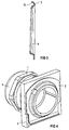
- FIG. 5 shows a sheet metal nut in a perspective view 3 with design of the anti-rotation device by shaping the sheet metal nut 3 with respect to its peripheral edge 9 and the bend 10.
- the sheet metal nuts 3 can not only in one piece but can also be made in several parts, as shown in FIG. 5 in principle represents, so that several cables 6 by screwing elements 1 can be fixed next to or on top of each other.
- Tin box 20 formed housing, in the wall 2 ' Recesses with thread contour 8, i.e. a thread or Part of a thread are shown.
- Tin box and Threads can be produced by deep drawing. Particularly advantageous is to tin box 20 and thread contour in one To produce a deep-drawing process.
- the thread contour 8 itself is also in the sheet metal box 20 memorable or punchable.
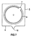
- FIG. 7 shows a sheet metal nut 3 with a nose 12 as an anti-rotation device.
- Stainless steel and spring band steel are preferred as sheet types and high-strength sheet steel.
Landscapes
- Engineering & Computer Science (AREA)
- Architecture (AREA)
- Civil Engineering (AREA)
- Structural Engineering (AREA)
- Installation Of Indoor Wiring (AREA)
- Insertion, Bundling And Securing Of Wires For Electric Apparatuses (AREA)
Abstract
Description
Die Erfindung betrifft eine Vorrichtung zur Fixierung von einer Kabelverschraubung an Wandungen von geschlossenen oder halboffenen Gehäusen, wobei vor der Wandung befindliche Elemente über zumindest eine Ausnehmung der Wandung mit hinter der Wandung befindlichen Elementen über zumindest ein Kabel verbunden ist, wobei das Verschraubungselement in der Ausnehmung zur Kabelführung vorgesehen ist und Mittel vorhanden sind, die das Verschraubungselement an der Wandung fixieren.The invention relates to a device for fixing a Cable gland on walls of closed or half-open housing, with elements located in front of the wall over at least one recess of the wall behind the wall elements via at least one cable is connected, wherein the screw element in the recess is provided for cable routing and means available are that fix the screw element on the wall.
Zur Fixierung von Kabeln werden vorzugsweise Verschraubungen in Klemmenkästen verwendet, z.B. von Elektromotoren oder in Nieder- oder Mittelspannungsschaltschränken. Es wird ein Loch mit einem Gewinde in die Wandung eines Gehäuses gebohrt oder es wird eine Metallmutter mit einem Gewinde verwendet um die Kabelverschraubung zu fixieren. Es werden auch Kunststoffmuttern für den gleichen Zweck eingesetzt.Screws are preferably used to fix cables used in terminal boxes, e.g. of electric motors or in Low or medium voltage control cabinets. It will be a hole drilled with a thread in the wall of a housing or a metal nut with a thread is used around the Fix cable gland. There will also be plastic nuts used for the same purpose.
Nachteilig dabei ist, dass diese Kunststoffmuttern aufgrund ihrer Materialeigenschaften nicht bei allen Umgebungstemperaturen eingesetzt werden können. Bei Verwendung einer Gewindemutter muss diese bei der Montage mit einem Schraubenschlüssel gegen Verdrehen gesichert werden.The disadvantage here is that these plastic nuts are due to their material properties not at all ambient temperatures can be used. When using a threaded nut this must be done with a wrench during assembly secured against twisting.
Nachteilig dabei ist außerdem, dass bei den bekannten Kabelverschraubungen der Fertigungsaufwand relativ hoch ist, da nach Einbringen der Bohrung in die Wandung des Gehäuses ein Gewinde vorzusehen ist, das durch eine spanende Bearbeitung erzeugt werden muss.Another disadvantage is that with the known cable glands the manufacturing effort is relatively high because after drilling the hole in the wall of the housing Thread is to be provided by machining must be generated.
Ausgehend davon liegt der Erfindung die Aufgabe zugrunde, eine Vorrichtung zur Fixierung von Verschraubungselementen zu schaffen, die durch einfache Konstruktion und preiswertem Herstellverfahren die bisherigen Verdrehsicherungen und Fixierungen ersetzen kann.Based on this, the object of the invention is a Device for fixing screw elements create by simple construction and inexpensive Manufacturing process the previous anti-rotation and fixation can replace.
Die Lösung der gestellten Aufgabe gelingt dadurch, dass das Verschraubungselement zumindest einen Gewindegang aufweist und durch zumindest ein Blechelement fixierbar ist.The task is solved by the fact that Screwing element has at least one thread and can be fixed by at least one sheet metal element.
Das Blechelement ist vorzugsweise als Blechmutter oder Teil eines Gehäuses ausgebildet.The sheet metal element is preferably a sheet metal nut or part of a housing.
Der Vorteil dabei ist, dass Blechmuttern einfach herzustellen sind. Bei Blechmuttern wird die Gewindekontur, d.h. ein Gewindegang oder ein Teil eines Gewindeganges durch Tiefziehen geformt. Dabei kann die Gewindekontur auch Teil eines Gehäuseteils oder Gehäuses sein. Damit stellt sich bereits bei der Herstellung derartiger Blechmuttern eine erheblicher Kostenreduktion ein, die sich insbesondere bei hohen Stückzahlen bemerkbar macht. Die Blechmutter weisen gegenüber herkömmlichen Muttern mit geschnittenem Gewinde ausreichende mechanische Eigenschaften auf. Dies resultiert aus der Tatsache, dass sich das Blechteil mit tiefgezogenem Gewindegang beim Festziehen der Schraube auf den Gewindekern aufzieht.The advantage is that sheet metal nuts are easy to manufacture are. For sheet metal nuts, the thread contour, i.e. a thread or part of a thread by deep drawing shaped. The thread contour can also be part of a housing part or housing. This already arises at the Manufacture of such sheet nuts a significant cost reduction a, which is particularly in large quantities noticeable. The sheet metal nut show compared to conventional Adequate mechanical nuts with cut threads Properties on. This results from the fact that the sheet metal part with deep-drawn thread at Tighten the screw on the thread core.
Durch Anbringen einer Verdrehsicherung an der Blechmutter, die durch Formgebung der Blechmutter z.B. durch Nasen ausgeführt ist, wird gewährleistet, dass sich das Gewinde selbsttätig auf den Gewindegang des Verschraubungselements aufzieht. Die Verdrehsicherung durch Formgebung der Blechmutter stellt sich vorzugsweise auch durch Wechselwirkung mit benachbarten Gehäuseteilen ein, z.B. Klemmenkästen.By attaching an anti-rotation device to the sheet metal nut, which by shaping the sheet metal nut e.g. carried out by noses ensures that the thread is self-acting on the thread of the screw element. The anti-rotation lock by shaping the sheet metal nut arises preferably also through interaction with neighboring ones Housing parts, e.g. Terminal boxes.
Die Verdrehsicherung ist auch als Nase ausbildbar, die sich in einer Bohrung im Gehäuse fixiert. Ebenso ist die Verdrehsicherung als Sperrkantprägung oder durch anschweißen der Blechmutter am Gehäuse ausbildbar. The anti-rotation device can also be formed as a nose fixed in a hole in the housing. The anti-rotation device is also as embossed edges or by welding the Sheet metal nut can be formed on the housing.
Die Erfindung sowie weitere vorteilhafte Ausgestaltungen der Erfindung sind anhand schematisch dargestellter Ausführungen im folgenden erläutert. Darin zeigen:
- FIG 1
- den Längsschnitt eines Verschraubungselements durch die Wandung und die Fixierung durch eine Blechmutter,
- FIG 2
- die Blechmutter,
- FIG 3
- eine Seitenansicht der Blechmutter,
- FIG 4
- eine perspektivische Darstellung eines Verschraubungselements mit einer Blechmutter,
- FIG 5
- eine perspektivische Darstellung einer Blechmutter mit zwei nebeneinander angeordneten Gewinden,
- FIG 6
- Blechkasten mit Gewindegang,
- FIG 7
- Blechmutter mit Nase.
- FIG. 1
- the longitudinal section of a screw element through the wall and the fixation by a sheet metal nut,
- FIG 2
- the sheet metal nut,
- FIG 3
- a side view of the sheet metal nut,
- FIG 4
- 1 shows a perspective illustration of a screwing element with a sheet metal nut,
- FIG 5
- 1 shows a perspective illustration of a sheet metal nut with two threads arranged next to one another,
- FIG 6
- Tin box with thread,
- FIG 7
- Sheet metal nut with nose.
FIG 1 zeigt eine Vorrichtung zur Fixierung von Kabeln 6, mit
einem Verschraubungselement 1 an einer Wandung 2 eines nicht
näher dargestellten Gehäuses. Derartige Vorrichtungen sind
insbesondere in Gehäusen der Energietechnik einzusetzen. Bevorzugte
Anwendungsgebiete sind dort die Klemmenkästen elektrischer
Maschinen und Schaltschränke. Aber auch in der Datentechnik
sind derartige Vorrichtungen zur Fixierung von Kabeln
6 einzusetzen.1 shows a device for
Das Verschraubungselement 1 weist dabei, um eine erfindungsgemäße
Fixierung eines Kabels 6 zu erreichen, einen Gewindegang
11 auf, auf den die Blechmutter 3 durch den Einschraubvorgang
aufgezogen wird und durch eine in dieser Darstellung
nicht dargestellten Verdrehsicherung fixiert ist.The
Um Feuchtigkeit oder elektromagnetische Strahlung abzuschirmen,
sind Dichtungselemente 4 vorzusehen.To shield moisture or electromagnetic radiation,
FIG 2 zeigt eine Verdrehsicherung der Blechmutter 3, die
durch Formgebung der Umlaufkante 9 oder Biegungen 10 der
Blechmutter 3 geschaffen ist. Mit 7 ist dabei ein Ausschnitt
bezeichnet, der fertigungstechnisch als Gewindeanfang
und/oder -ende notwendig ist. Dabei tritt insbesondere mit
der Wandung 2 des Gehäuses, wie z.B. einer nicht näher dargestellten
Rippe 13 eine Wechselwirkung ein, die damit eine
Verdrehsicherung herstellt.2 shows an anti-rotation lock of the
FIG 3 zeigt in einem Querschnitt den Verlauf der Gewindekontur
8 der Blechmutter 3 und eine Möglichkeit der Gestaltung
einer speziellen Verdrehsicherung durch Biegung 10 der Blechmutter
3.3 shows in a cross section the course of the
FIG 4 zeigt in einer perspektivischen Darstellung dass das
Verschraubungselement 1, das durch die Blechmutter 3 und der
Rippe 13 an der Wandung 2 fixiert ist. Mit 5 ist eine Mutter
mit innerem Kegel dargestellt, die ein nicht näher dargestelltes
Kunststoffelement zusammendrückt und dadurch eine
Zugentlastung für das Kabel 6 schafft.4 shows in a perspective view that the
FIG 5 zeigt in einer perspektivischen Darstellung eine Blechmutter
3 mit Ausgestaltung der Verdrehsicherung durch Formgebung
der Blechmutter 3 bzgl. ihrer Umlaufkante 9 und der Biegung
10. Die Blechmuttern 3 können nicht nur einteilig sondern
auch mehrteilig ausgeführt werden, wie FIG 5 prinzipiell
darstellt, so dass mehrere Kabel 6 durch Verschraubungselemente
1 neben oder übereinander fixierbar sind.5 shows a sheet metal nut in a
FIG 6 zeigt in einer perspektivischen Darstellung ein als
Blechkasten 20 ausgebildetes Gehäuse, in dessen Wandung 2'
Ausnehmungen mit Gewindekontur 8, d.h. einem Gewindegang oder
Teil eines Gewindeganges dargestellt sind. Blechkasten und
Gewindegang sind durch Tiefziehen herstellbar. Besonders vorteilhaft
ist es, Blechkasten 20 und Gewindekontur in einem
Tiefziehvorgang herzustellen.6 shows a perspective view of an as
Die Gewindekontur 8 selbst ist auch in den Blechkasten 20
einpräg- oder einstanzbar. The
FIG 7 zeigt eine Blechmutter 3 mit einer Nase 12 als Verdrehsicherung.7 shows a
Als Blecharten sind vorzugsweise Edelstahl, Federbandstahl und hochfestes Stahlblech zu verwenden.Stainless steel and spring band steel are preferred as sheet types and high-strength sheet steel.
Claims (8)
Applications Claiming Priority (2)
| Application Number | Priority Date | Filing Date | Title |
|---|---|---|---|
| DE10141801 | 2001-08-27 | ||
| DE2001141801 DE10141801A1 (en) | 2001-08-27 | 2001-08-27 | Device for fixing cable glands |
Publications (1)
| Publication Number | Publication Date |
|---|---|
| EP1289086A1 true EP1289086A1 (en) | 2003-03-05 |
Family
ID=7696674
Family Applications (1)
| Application Number | Title | Priority Date | Filing Date |
|---|---|---|---|
| EP02018377A Ceased EP1289086A1 (en) | 2001-08-27 | 2002-08-14 | Device for fixing a cable gland |
Country Status (2)
| Country | Link |
|---|---|
| EP (1) | EP1289086A1 (en) |
| DE (1) | DE10141801A1 (en) |
Cited By (1)
| Publication number | Priority date | Publication date | Assignee | Title |
|---|---|---|---|---|
| EP2551978B1 (en) * | 2011-07-29 | 2020-09-23 | Delphi Technologies, Inc. | Device for running an electric line through a housing |
Citations (4)
| Publication number | Priority date | Publication date | Assignee | Title |
|---|---|---|---|---|
| US2236130A (en) * | 1939-09-15 | 1941-03-25 | Harry E Betebenner | Locking key for outlet boxes |
| FR2257811A1 (en) * | 1974-01-14 | 1975-08-08 | Illinois Tool Works | Formed sheet steel screwed nut - uses alternate bent segments on inner periphery give thread form which engages thread on bolt |
| GB2208338A (en) * | 1987-07-23 | 1989-03-22 | Brian David Hamblin | Earth connection and seal |
| EP1059716A1 (en) * | 1999-06-07 | 2000-12-13 | Robert K. Sheehan | Lip threaded lock nut for electrical conduit |
Family Cites Families (3)
| Publication number | Priority date | Publication date | Assignee | Title |
|---|---|---|---|---|
| DE2620481C3 (en) * | 1976-05-08 | 1984-04-05 | Fa. A. Raymond, 7850 Lörrach | Self-locking sheet metal nut |
| DE9312476U1 (en) * | 1993-08-20 | 1993-10-21 | Wiska Hoppmann & Mulsow Gmbh | Cable socket |
| US5929383A (en) * | 1997-04-07 | 1999-07-27 | Thomas & Betts Corporation | Rotationally unrestrained grounding coupling for external grounding of fittings |
-
2001
- 2001-08-27 DE DE2001141801 patent/DE10141801A1/en not_active Withdrawn
-
2002
- 2002-08-14 EP EP02018377A patent/EP1289086A1/en not_active Ceased
Patent Citations (4)
| Publication number | Priority date | Publication date | Assignee | Title |
|---|---|---|---|---|
| US2236130A (en) * | 1939-09-15 | 1941-03-25 | Harry E Betebenner | Locking key for outlet boxes |
| FR2257811A1 (en) * | 1974-01-14 | 1975-08-08 | Illinois Tool Works | Formed sheet steel screwed nut - uses alternate bent segments on inner periphery give thread form which engages thread on bolt |
| GB2208338A (en) * | 1987-07-23 | 1989-03-22 | Brian David Hamblin | Earth connection and seal |
| EP1059716A1 (en) * | 1999-06-07 | 2000-12-13 | Robert K. Sheehan | Lip threaded lock nut for electrical conduit |
Cited By (1)
| Publication number | Priority date | Publication date | Assignee | Title |
|---|---|---|---|---|
| EP2551978B1 (en) * | 2011-07-29 | 2020-09-23 | Delphi Technologies, Inc. | Device for running an electric line through a housing |
Also Published As
| Publication number | Publication date |
|---|---|
| DE10141801A1 (en) | 2003-04-03 |
Similar Documents
| Publication | Publication Date | Title |
|---|---|---|
| EP3164911B1 (en) | Plug | |
| DE202012101639U1 (en) | Through housing | |
| WO2019101268A1 (en) | Cable feedthrough | |
| WO2012045430A2 (en) | Cable termination device | |
| WO2017182028A1 (en) | Securing assembly for securing a flange plate to an electrical enclosure housing, and a corresponding electrical enclosure housing | |
| EP3688851B1 (en) | Cable screw connection | |
| DE102018110026B4 (en) | Plastic electrical housing | |
| EP1289086A1 (en) | Device for fixing a cable gland | |
| DE102015107050A1 (en) | battery terminal | |
| DE102008057473B4 (en) | Grommet | |
| EP1750300B1 (en) | Electrical element | |
| EP3382833B1 (en) | Mounting assembly for a modular mounting system, such as a system for door communication and building electronic installation and mounting tool for such a mounting assembly | |
| EP1408190A1 (en) | Door hinge arrangement | |
| EP3790134A1 (en) | Cable entrance | |
| DE102010017440B4 (en) | Cable gland for a breakthrough in a wall | |
| WO1998049752A1 (en) | Shielded connecting device | |
| DE3636574C2 (en) | Waterproof housing, especially for encapsulating electrical and electronic components | |
| EP3317616B1 (en) | Fastening unit for a radio and/or sensor module | |
| DE102007008689A1 (en) | Earthing device for compensating a voltage has a casing to hold a cable lead-through for sealing onto a cable when assembled | |
| DE19824068A1 (en) | Electrically insulating screw connection to join two workpieces, e.g. for fixing electric drive to frame of vehicle sunroof | |
| EP3716427A1 (en) | Flange plate for mounting in an opening in a housing wall | |
| DE102012010816B4 (en) | Cable termination and method | |
| DE894411C (en) | Arrangement for strain relief of the line connections on housings of electrical devices | |
| DE102020120838A1 (en) | Clamping screw with improved insulating distance | |
| DE102022201723A1 (en) | Electrical connector, contact insert and method for manufacturing an electrical connector |
Legal Events
| Date | Code | Title | Description |
|---|---|---|---|
| PUAI | Public reference made under article 153(3) epc to a published international application that has entered the european phase |
Free format text: ORIGINAL CODE: 0009012 |
|
| AK | Designated contracting states |
Kind code of ref document: A1 Designated state(s): AT BE BG CH CY CZ DE DK EE ES FI FR GB GR IE IT LI LU MC NL PT SE SK TR Designated state(s): AT BE BG CH CY CZ DE DK EE ES FI FR GB GR IE IT LI LU MC NL PT SE SK TR |
|
| AX | Request for extension of the european patent |
Extension state: AL LT LV MK RO SI |
|
| 17P | Request for examination filed |
Effective date: 20030818 |
|
| AKX | Designation fees paid |
Designated state(s): DE FR GB |
|
| 17Q | First examination report despatched |
Effective date: 20050324 |
|
| STAA | Information on the status of an ep patent application or granted ep patent |
Free format text: STATUS: THE APPLICATION HAS BEEN REFUSED |
|
| 18R | Application refused |
Effective date: 20060928 |